

Page 1
Filtral 2500 UVC/5000 UVC
Page 2

2
Page 3
3
Page 4

4
Page 5
5
Page 6
6
Page 7

7
Page 8

Translation of the original Operating Instructions
- GB -
- GB -
Information about these operating instructions
Welcome to OASE Living Water. You made a good choice with the purchase of this product Filtral 2500 UVC / 5000
UVC.
Prior to commissioning the unit, please read the instructions of use carefully and fully familiarise yourself with the unit.
Ensure that all work on and with this unit is only carried out in accordance with these instructions.
Adhere to the safety information for the correct and safe use of the unit.
Keep these instructions in a safe place! Please also hand over the instructions when passing the unit on to a new
owner.
Symbols used in these instructions
The symbols used in this operating manual have the following meanings:
Risk of injury to persons due to dangerous electrical voltage
This symbol indicates an imminent danger, which can lead to death or severe injuries if the appropriate measures are not taken.
Risk of personal injury caused by a general source of danger
This symbol indicates an imminent danger, which can lead to death or severe injuries if the appropriate measures are not taken.
Important information for trouble-free operation.
Intended use
Filtral 2500 UVC / 5000 UVC, in the following termed "unit", and all other parts from the delivery scope may be used
exclusively as follows:
− For cleaning garden ponds.
− For operation with clean water.
− Operation under observance of the technical data.
The UVC lamp installed in the unit is intended to kill algae and bacteria in the pond water. Even in small doses, its
radiation is harmful for eyes and skin. Never use the UVC lamp in a defective housing or outside the housing, or any
other purpose other than that intended.
The following restrictions apply to the unit:
− Do not use in swimming ponds.
− Never use the unit to convey fluids other than water.
− Never run the unit without water.
− Do not use for commercial or industrial purposes.
− Do not use in conjunction with chemicals, foodstuff, easily flammable or explosive substances.
Safety information
Hazards to persons and assets may emanate from this unit if it is used in an improper manner or not in accordance
with its intended use, or if the safety instructions are ignored.
This unit can be used by children from the age of 8 and by persons
with physical, sensory or mental impairments or lack of experience
and knowledge, as long as they are supervised or instructed on how
to use the unit safely and are able to understand the potential hazards. Do not allow children to play with the unit. Do not allow children
to clean or maintain the unit without close supervision.
Hazards encountered by the combination of water and electricity
− The combination of water and electricity can lead to death or severe injury from electrocution, if the unit is incorrectly
connected or misused.
− Prior to reaching into the water, always switch off the mains voltage to all units used in the water.
Correct electrical installation
− Electrical installations must meet the national regulations and may only be carried out by a qualified electrician.
− A person is regarded as a qualified electrician, if, due to his/her vocational education, knowledge and experience, he
or she is capable of and authorised to judge and carry out the work commissioned to him/her. This also includes the
recognition of possible hazards and the adherence to the pertinent regional and national standards, rules and regulations.
13
Page 9

- GB -
− For your own safety, please consult a qualified electrician.
− The unit may only be connected when the electrical data of the unit and the power supply coincide. The unit data is
to be found on the unit type plate or on the packaging, or in this manual.
− Ensure that the unit is fused for a rated fault current of max. 30 mA by means of a fault current protection device.
− Extension cables and power distributors (e. g. outlet strips) must be suitable for outdoor use.
− Ensure that the power connection cable cross section is not smaller than that of the rubber sheath with the identifi-
cation H05RN-F. Extension cables must meet DIN VDE 0620.
− Protect the plug connections from moisture.
− Only plug the unit into a correctly fitted socket.
Safe operation
− Never operate the unit if either the electrical cables or the housing are defective!
− Do not carry or pull the unit by its electrical cable.
− Route cords/hoses/lines in a way that they are protected against damage, and ensure that they do not present a
tripping obstacle.
− Only open the unit housing or its attendant components, when this is explicitly required in the operating instructions.
− Only execute work on the unit that is described in this manual. If problems cannot be overcome, please contact an
authorised customer service point or, when in doubt, the manufacturer.
− Only use original spare parts and accessories for the unit.
− Never carry out technical modifications to the unit.
− Only operate the unit if no persons are in the water!
− Keep the socket and power plug dry.
Installation
Filtral 2500
Unit assembly (Fig. A)
Assemble the branch valve (12), the connection element for the ball joint (19), the nozzle tube (11) with the clamping
screw (10), nozzle mounting (9) and nozzle insert (8), then screw the assembly on the connection thread of the UVC
water housing (26) including the washer (14). The fountain height and shape depend on the nozzle insert (8) used.
If required, connect an additional hose for features or a water course to the lateral separately regulated connection of
the branch valve (12).
If you only use the lateral outlet at the branch valve (12), close the upper outlet using the cover cap (38).
Filtral 5000:
Connecting the venting pump – option (Fig. V-Y)
If you wish to enrich the water with additional oxygen, connect the venting pump (Aqua Oxy) prior to installing the unit.
The Aqua Oxy scope of delivery includes the aeration stone and the hose.
Open the filter housing (Fig. V): Pull the clamps on both sides of the bottom strainer casing (2) to the side and lift off
the top strainer casing (1). Remove the foam filter (3).
Connect the aeration stone (figure W): Inside the housing, connect the aeration stone (25) with a section of the hose
(4) to the air connector (5) and place the aeration stone (25) between the gravel bags (24). Ensure that the hose is not
kinked. Connect the aeration pump (Aqua Oxy) to the air connector (5) outside of the housing. Read the aeration pump
documentation.
Close the filter housing (Fig. Y): Place the foam filter (3) in the bottom strainer casing (2). Attach the top strainer casing
(1) and press it onto the bottom strainer casing (2) until the clamps engage in the bottom strainer casing.
Important: Lead the connection cable (7) through the cable opening in the bottom strainer casing (2) and route the
cable such that pinching is avoided.
Unit assembly (Fig. A)
Assemble the reduction element (13), branch valve (12), nozzle tube (11) with the clamping screw (10), nozzle mounting (9) and nozzle insert (8), then screw the assembly on the connection thread of the UVC water housing (26) including the washer (14). The fountain height and shape depend on the nozzle insert (8) used.
If required, connect an additional hose for features or a water course to the lateral separately regulated connection of
the branch valve (12). For this purpose, screw the reduction element (15) and the stepped hose adapter (16) on the
lateral outlet of the branch valve (12).
14
Page 10

- GB -
Installation
Set-up the unit
Place the unit in the pond on a horizontal, firm and sludge free ground and ensure that it is completely covered by
water.
Setting the fountain/water feature (Fig. B, C)
Pull the nozzle tube (11) to the desired length. Undo the clamping screw (10), vertically align the nozzle tube (11) and
fasten the clamping screw (10) hand tight.
Fully open the rotary regulator (18) for the fountain. The rotary regulator (17) for the features or the water course is
also used to control the fountain/water feature. The additional water recirculation via the lateral outlet improves the
filtering effect, even if the feature or the water course is not connected.
Start-up
Attention! Dangerous electrical voltage.
Possible consequences: Death or severe injury.
Protective measures:
− Prior to reaching into the water, disconnect the power supply to all units used in the water.
− Disconnect the power plug prior to carrying out work on the unit.
Attention! Sensitive electrical components.
Possible consequence: The unit will be destroyed.
Protective measure: Do not connect the unit to a dimmable power supply.
Switching on: Connect power plug to the socket. The unit switches on immediately when the power connection is
established.
Switching off: Disconnect the power plug.
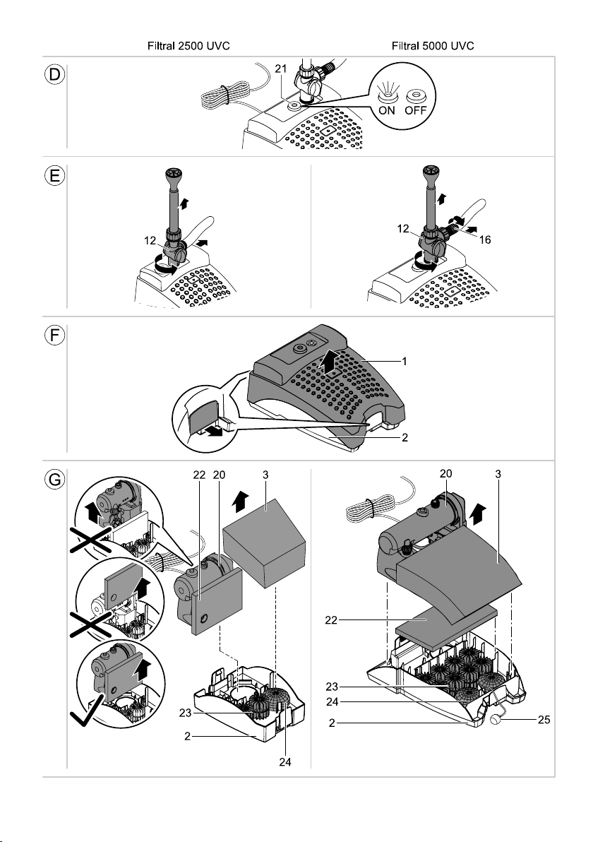
The indicator lamp (Fig. A, 21) indicates the ON/OFF status of the UVC lamp.
Malfunctions
The unit is not operating No mains voltage Check mains voltage
Delivery or fountain height insufficient or not
consistent,
Cloudy water
UVC lamp does not light up
Unit switches off after a short running period Water temperature too high Note maximum water temperature of +35°
Malfunction Cause Remedy
Flow regulator excessively throttled Set flow regulator
Nozzle blocked Unscrew and clean the nozzle insert
Excessive pressure losses in the hoses Reduce hose length and connecting parts to a
Intake openings blocked Clean housing
Filters clogged Clean filters
Rotor blocked Clean rotor
Pond extremely dirty Remove algae and leaves from the pond,
Quartz glass tube soiled Remove UVC clarifying unit and clean the
Lamp overheated. The temperature switch has
switched off the lamp
UVC lamp defective Replace the UVC lamp
UVC lamp is not correctly seated in the socket Correctly insert the UVC lamp into the socket
minimum, route hoses as straight as possible
change the water
quartz glass tube
The lamp will automatically switch on again
once cooled down
15
Page 11

- GB -
Maintenance and cleaning
Attention! Dangerous electrical voltage.
Possible consequences: Death or severe injury.
Protective measures:
− Prior to reaching into the water, disconnect the power supply to all units used in the water.
− Disconnect the power plug prior to carrying out work on the unit.
Attention! Ultra-violet radiation.
Possible consequences: Eye or skin injury from burns.
Protective measures:
− Never operate the UVC lamp outside its housing.
− Never operate the UVC lamp in a housing that is defective.
Filtral 2500: Opening the filter housing and cleaning the different filters (Fig. E-G)
Unscrew the branch valve (12) and the attachment elements. Pull the clamps on both sides of the bottom strainer
casing (2) to the side and lift off the top strainer casing (1). Remove the foam filter (3) and the UVC clarifying unit
including pump (20), and the fine foam filters (22), bio surface elements (23) and the gravel bag (24).
Clean the bottom strainer casing (2) and the top strainer casing (1) with clear water using a brush. Wash out foam
filters (3, 22), bio-surface elements (23) and the gravel bag (24) under running water. Do not use chemical cleaning
agents as they would kill the micro-organisms in the different filter media. At the beginning, this entails a reduced filter
capacity.
Filtral 5000: Opening the filter housing and cleaning the different filters (Fig. E-G)
Unscrew the branch valve (12) and the attachment elements. Pull the clamps on both sides of the bottom strainer
casing (2) to the side and lift off the top strainer casing (1). Remove the UVC clarifying unit including pump (20), foam
filters (3, 22), bio surface elements (23) and gravel bags (24). When the aeration stone (25) is connected, put it to the
side. Clean the bottom strainer casing (2) and the top strainer casing (1) with clear water using a brush. Wash out foam
filters (3, 22), bio-surface elements (23) and gravel bags (24) under running water. Do not use chemical cleaning
agents as they would kill the micro-organisms in the different filter media. At the beginning, this entails a reduced filter
capacity.
Unscrew pump (28) from the UVC water housing (26). Unscrew the pump lid (27) counter-clockwise (bayonet closure)
and remove rotor (29). Clean all components using clean water and a brush. After cleaning the pump, reassemble in
the reverse order.
Opening and cleaning the UVC water housing
Note!
A safety switch prevents switching on the UVC lamp as long as the UVC water housing is removed.
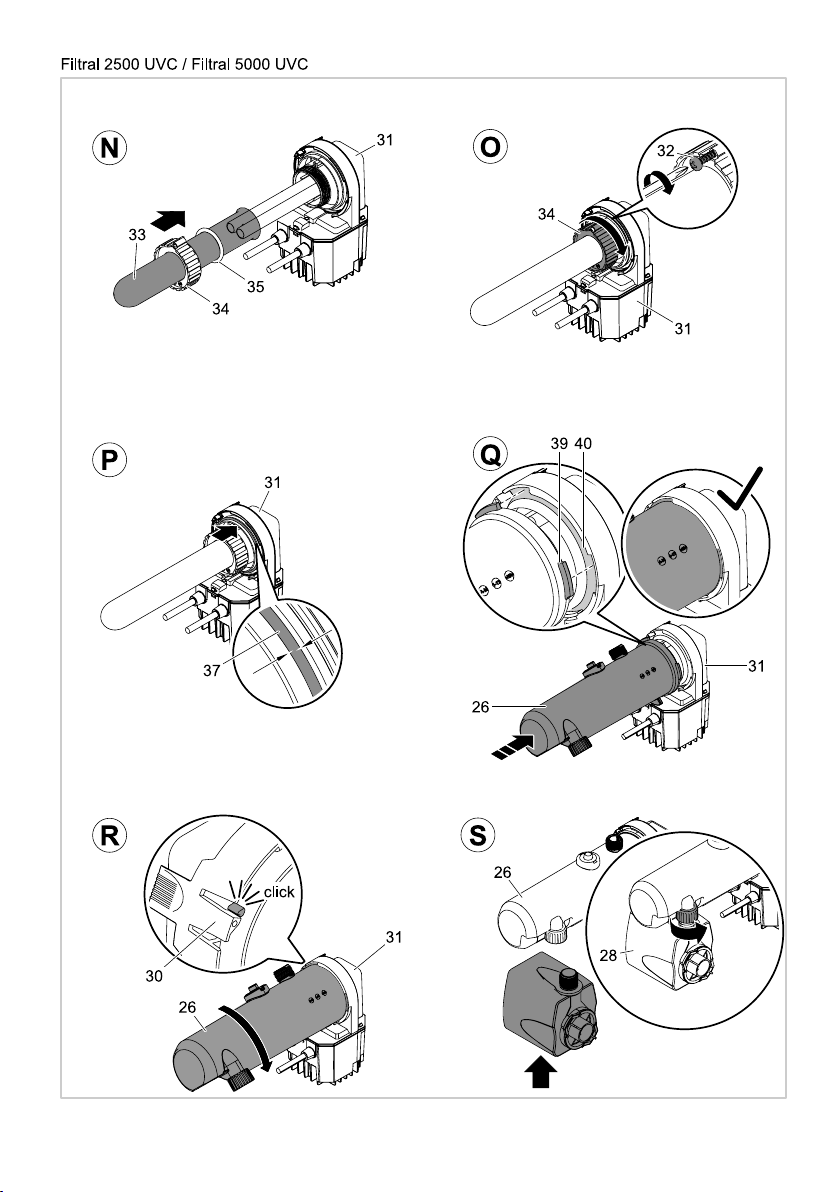
The UVC water housing (26) is fastened to the unit head (31) by means of a bayonet closure. Press on the engagement lug (30) at the unit head (31), turn the UVC water housing (26) counter-clockwise and carefully pull it off the unit
head (31). Clean the UVC water housing (26) under running water. Check the quartz glass (33) for damage and clean
its outer face with a moist cloth.
Note: For an optimum filter performance, we recommend to replace the UVC lamp after approx. 8000 operating hours.
Refer to 'Replace UVC lamp'.
Filtral 2500: Assembly of the unit (Fig. S-V)
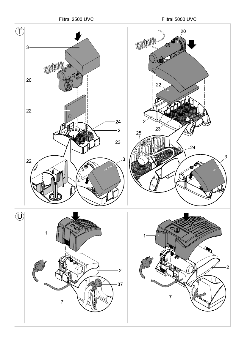
Bolt the pump (28) to the UVC water housing (26) using the union nut. Insert fine foam filter (22) in the bottom strainer
casing (2), place the bio surface elements (23) and the gravel bag (24) in the bottom strainer casing (2). Insert the UVC
clarifying unit including the pump (20). Insert the foam filter (3). Attach the top strainer casing (1) and press it onto the
bottom strainer casing (2) until the clamps engage in the bottom strainer casing. Important: Guide the connection
cable (7) through the cable opening at the bottom strainer casing (2) and clip with the cable kink protection in the
bottom strainer casing (U, 37).
16
Page 12

Filtral 5000: Assembly of the unit (Fig. S-V)
- GB -
Bolt the pump (28) to the UVC water housing (26) using the union nut. Place the bio surface element (23) and gravel
bags (24) in the bottom strainer casing (2). Place the aeration stone (25) between the gravel bags (24). Ensure that the
hose is not kinked. Place the foam filters (3, 22) in the bottom strainer casing (2). Insert the UVC clarifying unit including the pump (20). Attach the top strainer casing (1) and press it onto the bottom strainer casing (2) until the clamps
engage in the bottom strainer casing. Important: Lead the connection cable (7) through the cable opening in the
bottom strainer casing (2) and route the cable such that pinching is avoided.
UVC lamp replacement (Fig. L-S)
Attention! Breakable glass.
Possible consequences: Injury of your hands caused by cuts.
Protective measures: Handle both quartz glass and UVC lamp with care.
Attention! Ultra-violet radiation.
Possible consequences: Eye or skin injury from burns.
Protective measures:
− Never operate the UVC lamp outside its housing.
− Never operate the UVC lamp in a housing that is defective.
− Open the UVC water housing (see "Opening and cleaning the UVC water housing").
− Remove the self-tapping screw (32).
− Unscrew the clamping screw (34) from the unit head (31) by turning counter-clockwise.
− Pull off the quartz glass (33) and the O-ring (35) while slightly turning the unit head (31).
− Pull out the UVC lamp (36) and replace.
Important: Only use lamps the identification and capacity data of which correspond to the information on the type
plate.
− Check the quartz glass (33) and the O ring (35) for damage.
− Insert the quartz glass (33) including the O ring (35) against the stop in the unit head (31).
− Tighten the clamping screw (34) clockwise up to the stop.
− Turn in and tighten the self-tapping screw (32).
− Close the UVC water housing (see "Closing the UVC water housing").
Storage/Over-wintering
Remove the unit at temperatures below zero degrees centigrade. Thoroughly clean and check the unit for damage.
Store the unit immersed in water or filled with water in a frost-free place. Do not flood the power plug!
Wearing parts
The UVC lamp, the different filters and the rotor are wear parts and are excluded from the warranty.
Disposal
Do not dispose of this unit with domestic waste! For disposal purposes, please use the return system provided.
Disable the unit beforehand by cutting off the cables.
Only dispose of the UVC lamp by using the return system provided for this purpose.
17
Page 13

ture
l’eau
Water tempera-
Température de
Wassertemperatur
agua
água
dell'acqua
Temperatura
Temperatura da
Temperatura del
Watertemperatuur
Vanntemperatur
Vandtemperaturen
Vattentemperatur
+4 … +35 °C
Veden lämpötila
Teichgröße ohne
Filterfläche Teichgröße mit
Max. Wasser-
Max. Förder-
UVC-Lampe Anschluss
Fischbesatz
Fischbesatz
säule
leistung
Druckseite
aufname
Pond size w/o
Filter surface Pond size with
Max. flow rate Max. head
UVC lamp Connection,
fish population
fish population
height
pressure side
sumption
stand
Grootte vijver
zonder visbe-
Grootte vijver
met visbestand
in
Pompcapaciteit Waterkolom Filter oppervlak
drukzijde
UVC-lamp Aansluiting
opname
Tamaño del
estanque sin
Tamaño del
estanque con
filtro
Superficie de
agua
Columna de
elevación
Capacidad de
de presión
Lámpara UVC Conexión lado
potencia
peces
peces
poissons
bassin sans
Dimension de
poissons
bassin avec
Dimension de
filtrante
Colonne d'eau Enveloppe
refoulement
Capacité de
côté pression
Lampe UVC Raccord
absorbée
peixes
Grandezza
tanque sem
Capacidade
peixes
Grandezza
tanque com
Capacidade
filtro
Superficie
Superfície do
água
Débito Coluna de
Portata Colonna
de pressão
Lâmpada UVC Conexão lado
Lampada UVC Collegamento
absorvida
pesci
laghetto senza
laghetti con pesci
filtro
d'acqua
lato mandata
assorbita
Dammens
størrelse, uden
størrelse, med
Vandsøjle Filterflade Dammens
kapacitet
Transport-
trykside
fiskebestand
fiskebestand
bestand
uten fiske-
Damstørrelse
bestand
med fiske-
Kapasitet Vannsøyle Filterflate Damstørrelse
trykkside
(utan fisk)
ilman kaloja
Lammen koko
Dammens volym
(med fisk)
kalojen kanssa
Vattenpelare Filteryta cm² Dammens volym
Matnings
prestanda
Syöttöteho Vesipylväs Suodatuspint Lammen koko
½ " 600 l/h 1.3 m 232 cm² ≤ 1.3 m³ ≤ 2.5 m³
½ " 1100 l/h 2.3 m 564 cm² ≤ 2.5 m³ ≤ 5 m³
liitäntä
trycksidan
(UV-C)
(UV-C)
7 W TC-S
11 W TC-S
3.3 kg ~ 230 V, 50 Hz 20 W
4.5 kg ~ 230 V, 50 Hz 35 W
Mål Vekt Merkespenning Effektopptak UV-lampe Tilkobling
Mått Vikt övre märkspänning Effekt UVC-lampa Anslutning på
Mitat Paino Nimellisjännite Ottoteh o UVC-lamppu Painepuolen
250 × 185
380 × 290
× 160 mm
Dimensiones Peso Tensión asignada Consumo de
ES
Dimensões Peso Voltagem dimensionada Potê ncia
PT
Dimensioner Vægt Netspænding Effektforbrug UVC-pære Tilslutning,
IT
DK
NO
SE
Afmetingen Gewicht Dimensioneringsspanning Vermogens-
Dimensions Weight Rated voltage Power con-
Dimensions Poids Tension de mesure Puissance
Abmessungen Gewicht Bemessungs spannung Leistungs-
DE
GB
FR
Technische Daten
NL
Dimensioni Peso Tensione di misurazione Potenza
× 160 mm
FI
Filtral
2500 UVC
Filtral
5000 UVC
118
Page 14

apei
vode
wody
Temperatura
Vízhőmérséklet
vode
Temperatura
Teplota vody
Temperatura
Teplota vody
на водата
Temperatura
Температура
Температурата
水温
води
воды
Температура
+4 … +35 °C
119
A tó mérete
halállomány
halállománnyal
Szállítási teljesítmény Vízoszlop Szűrőfelület A tó mérete
csatlakozás
UVC-lámpa Nyomóoldali
nélkül
bez zarybienia
Velikost jezírka
Wielkość stawu
zarybieniem
Wielkość stawu z
filtracyjna
Słup wody Powierzchnia
Wydajność
pompowania
Dopravní výkon Vodní sloupec Plocha filtru Velikost jezírka
strona
ciśnienia
Przyłącze
towa
staleža
bez riba
piscicolă
populaţie
без риби
iazului fără
brez ribjega
Veličina jezera
Velikost ribnika
Veľkosť jazierka
bez obsádky rýb
bez rybí obsádky
ribjim staležem
s obsádkou rýb
s rybí obsádkou
strana výtlaku
Veličina jezera s
Velikost ribnika z
površin
Dopravný výkon Vodný stĺpec Ploc ha filtru Veľkosť jazierka
Protočni kapacitet Vodeni stup Površina
Črplana zmogljivost Vodni steber F iltrska
tlačni strani
strana výtlaku
UVC-žarulja Priključak na
Размер на
Dimensiunea
водния басейн
ribama
Dimensiunea
filtra
Suprafaţa
Debit de pompare Coloană de
potisnoj strani
Conexiune pe
Lampă cu
риби
piscicolă
populaţie
iazului cu
Размер на
водния басейн с
filtrului
филтъра
apă
Дебит Воден стълб Площ на
страна
refulare
напорна
ultraviolete
UVC - лампа Връзка
рыб
未养鱼的
Величина
ставка без риби
Величина
ставка із рибою
Площа
фільтру
стовп
Продуктивність Водяний
зі сторони
нагнітання
Підключення
лампа
Ультрафіолетова
池塘面积
Размер пруда
при отсутствии
рыб
池塘面积
при наличии
Размер пруда
фильтра
Поверхность
столб
输送能力 水柱 过滤面积 养有鱼的
Производительность Водяной
½ " 600 l/h 1.3 m 232 cm² ≤ 1.3 m³ ≤ 2.5 m³
½ " 1100 l/h 2.3 m 564 cm² ≤ 2.5 m³ ≤ 5 m³
的接口
стороны
напорной
Подключение
(UV-C)
(UV-C)
7 W TC-S
УФ-лампа
Коротковолновая
11 W TC-S
napetost
energije
Potrošnja
Putere consu-
napon
Dimenzije Masa gornji nazivni
Dimensiuni Masă Tensiunea
HR
RO
mată
мощност
Потребявана
măsurată
напрежение
Размери Тегло Номинално
BG
мощности
Споживання
Потребление
електроенергії
напруга
напряжение
3.3 kg ~ 230 V, 50 Hz 20 W
4.5 kg ~ 230 V, 50 Hz 35 W
Размеры Вес расчетное
RU
尺寸 重量 额定电压 功耗 紫外线灯管 排水侧
CN
247 × 183
× 160 mm
Filtral
2500 UVC
380 × 290
× 160 mm
Filtral
5000 UVC
Розміри Вага розрахункова
UA
Příkon UVC zářivka Přípojka
felvétel
Méretek Súly mért feszültség Teljesítmény-
HU
Technische Daten
Príkon UVC žiarivka Prípojka
Pobór mocy Lam pa ultrafiole-
nowe
Wymiary Ciężar Napięcie znamio-
PL
napětí
Rozměry Hmotnost Domezovací
CZ
Rozmery Hmotnost’ dimen začné
SK
Poraba moči UVC-žarnica Priključek na
napätie
Dimenzije Teža dimenzionirana
SI
Page 15

DE
Staubdicht. Wasserdicht bis
2 m Tiefe.
GB
Dust tight. Submersible to 2 m
depth.
FR
Imperméable aux poussières.
Etanche à l'eau jusqu'à une
profondeur de 2 m.
NL
Stofdicht. Waterdicht tot een
diepte van 2 m.
ES
A prueba de polvo.
Impermeable al agua hasta
2 m de profundidad.
PT
À prova de pó. À prova de
água até 2 m de profundidade.
IT
A tenuta di polvere. Impermeabile all'acqua fino a 2 m di
profondità.
DK
Støvtæt. Vandtæt ned til 2 m
dybde.
NO
Støvtett. Vanntett ned til 2 m
dyp.
SE
Dammtät. Vattentät till 2 m
djup.
FI
Pölytiivis. Vesitiivis 2 m
syvyyteen asti
HU
Portömített. Vízálló 2 m-es
mélységig.
PL
Pyłoszczelny. Wodo szczelny
do 2 m głębokości.
CZ
Prachotěsný. Vodotěsný do
hloubky 2 m.
SK
Prachotesný. Vodotesný do
hĺbky 2 m.
SI
Ne prepušča prahu. Ne
prepušča vode do globinen
2 m.
HR
Ne propušta prašinu. Ne
propušta vodu do 2 m dubine.
RO
Etanş la praf. Etanş la apă,
până la o adâncime de 2 m.
BG
Защитено от прах.
Водоустойчив до дълбочина
2 м.
UA
Пилонепроникний.
Водонепроникний до 2 м.
RU
Пыленепрониц.
Водонепрониц. на глубине
до 2 м.
CN
防尘。至 2 米深防水。 注意!
Achtung!
Gefährliche UVCStrahlung!
Attention!
Dangerous UVC
radiation!
Attention !
Rayonnement UVC
dangereux !
Let op!
Gevaarlijke UVCstraling!
¡Atención!
Radiación UVC
peligrosa.
Atenção!
Radiação UVC
perigosa!
Attenzione!
Pericolosa radiazione
UVC!
Fare!
Farlig UVC-stråling!
NB!
Farlig UV-stråling!
Varning!
Farlig UVC-strålning!
Huomio!
Vaarallinen UVCsäteily!
Figyelem!
Veszélyes UVCsugárzás!
Uwaga!
Niebezpieczne
promieniowanie
ultrafioletowe!
Pozor!
Nebezpečné ultrafialové záření.
Pozor!
Nebezpečné ultrafialové žiarenie.
Pozor!
Nevarno UVC-sevanje!
Pažnja!
Opasno UVC zračenje!
Atenţie!
Radiaţii ultraviolete
periculoase!
Внимание!
Опасно
ултравиолетово
лъчение!
Увага!
Небезпечне
ультрафіолетове
випромінювання!
Внимание!
Опасное
коротковолновое
УФ-излучение!
危险的紫外线照射!
Bei Frost, das
Gerät deinstallieren!
Remove the unit at
temperatures below
zero (centigrade).
Retirer l’appareil en
cas de gel
Bij vorst het
apparaat
deïnstalleren!
Desinstale el
equipo en caso de
heladas.
Em caso de geada,
desinstalar o
aparelho!
In caso di gelo
disinstalllare
l'apparecchio!
Afmonter apparatet
ved frostvejr!
Ved frost, demonter
apparatet!
Demontera
apparaten innan
första frosten!
Laite on purettava
ennen pakkasia.
Fagy esetén a
készüléket le kell
szerelni!
W razie mrozu
zdeinstalować
urządzenie!
Při mrazu přístroj
odinstalovat!
Pri mraze prístroj
odinštalovať!
Ob zmrzali
demontirajte
napravo!
U slučaju mraza
deinstalirajte
uređaj!
În perioadele cu
îngheţ dezinstalaţi
aparatul !
При опасност от
измръзване
деинсталирайте
уреда!
Перед морозами
пристрій необхідно
демонтувати
При наступлении
морозов прибор
демонтировать!
霜冻时,拆卸设备 ! 易碎,小心
Zerbrechlich, mit Vorsicht
behandeln.
Achtung! Gefahr von Schnittverletzungen.
Breakable, handle with care.
Attention! Risk of injury from
cuts.
Fragile, manipuler avec
précaution.
Attention ! Danger de coupures.
Breekbaar, voorzichtig
behandelen
Let op!
Gevaar voor snijwonden
Frágil, trate con cuidado.
¡Atención! Peligro de lesiones
de corte.
Quebradiço, tratar com
cuidado.
Atenção! Risco de lesões de
corte.
Fragile, trattare con cautela.
Attenzione! Pericolo di lesioni
da taglio.
Skrøbelig, behandles forsigtigt.
OBS! Risiko for snitsår.
Skjørt glass, må behandles
forsiktig.
Forsiktig! Fare for kuttskader.
Bräckligt! Hanteras varsamt.
Varning! Risk för skärskador.
Särkyvää, käsiteltävä varoen.
Huomio! Viiltohaavan vaara.
Törékeny, óvatosan kezelje.
Figyelem! Vágási sérülések
veszélye.
Łamliwe, postępować ostrożnie.
Uwaga! Niebezpieczeństwo
skaleczenia.
Křehké, dbejte opatrnosti.
Pozor! Nebezpečí řezných
zranění.
Krehké, manipulujte s veľkou
opatrnosťou.
Pozor! Nebezpečenstvo vzniku
rezných poranení.
Krhko, zato ravnajte previdno.
Pozor! Nevarnost za poškodbe
pri rezanju.
Lomljivo, ophoditi sa pažnjom.
Pozor! Opasnost od posjekotina.
Casant, manevraţi cu atenţie.
Atenţie! Pericol de producere a
rănirilor prin tăiere.
Чупливо, манипулирайте
внимателно.
Внимание! Опасност от
порязване.
Поводитися обережно,
б’ється.
Увага! Небезпека
травмування порізами.
Бьющийся материал,
обращаться осторожно.
Внимание! Опасность
повреждений от пореза.
轻
放!
伤
注意!小心割
Nicht mit normalem
Hausmüll entsorgen!
Do not dispose of
together with household
waste!
Ne pas recycler dans les
ordures ménagères !
Niet bij het normale
huisvuil doen!
¡No deseche el equipo
en la basura doméstica!
Não deitar ao lixo
doméstico!
Non smaltire con normali
rifiuti domestici!
Må ikke bortskaffes med
det almindelige
husholdningsaffald
Ikke kast i alminnelig
husholdningsavfall!
Får inte kastas i
hushållssoporna!
Älä hävitä laitetta
tavallisen talousjätteen
kanssa!
A készüléket nem a
normál háztartási
szeméttel együtt kell
megsemmisíteni!
Nie wyrzucać wraz ze
śmieciami domowymi!
Nelikvidovat v normálním
komunálním odpadu!
Nelikvidovať v
normálnom komunálnom
odpade!
Ne zavrzite skupaj z
gospodinjskimi odpadki!
Nemojte ga bacati u
običan kućni otpad!
Nu aruncaţi în gunoiul
menajer !
Не изхвърляйте заедно
с обикновения
домакински боклук!
Не викидайте разом із
побутовим сміттям!
Не утилизировать
вместе с домашним
мусором!
。
不要同普通的家庭垃圾一
起丢弃!
Achtung!
Lesen Sie die Gebrauc hsanleitung
Attention!
Read the operating
instructions
Attention !
Lire la notice d'emploi
Let op!
Lees de gebruiksaanwijzing
¡Atención!
Lea las instrucciones de
uso
Atenção!
Leia as instruções de
utilização
Attenzione!
Leggete le istruzioni d'uso!
OBS!
Læs brugsanvisningen
NB!
Les bruksanvisningen
Varning!
Läs igenom
bruksanvisningen
Huomio!
Lue käyttöohje
Figyelem!
Olvassa el a használati
útmutatót
Uwaga!
Przeczytać instrukcję
użytkowania!
Pozor!
Přečtěte Návod k použití!
Pozor!
Prečítajte si Návod
na použitie
Pozor!
Preberite navodila za
uporabo!
Pažnja!
Pročitajte upute za
upotrebu!
Atenţie !
Citiţi instrucţiunile de
utilizare !
Внимание!
Прочетете упътването
Увага!
Читайте інструкцію.
Внимание!
Прочитайте инструкцию
по использованию
注意!
请阅读使用说明书。
120
Page 16

121
Page 17

122
Page 18

13639/01-14
 Loading...