

Page 1
Instruction Manual
Temp-100 and Temp-300
Dual-Input Thermocouple
Datalogging Thermometer
68X518203 Rev0 07/09
Page 2

Page 3

T
A
BLE OF CONTENTS
1. INTRODUCTION .......................................1
2. SAFETY PRECAUTIONS.......................... 2
3. SPECIFICATIONS .................................... 3
4. BATTERY INSTALLATION AND
REPLACEMENT........................................ 6
5. INSERTING AND REMOVING OPTIONAL
RUBBER ARMOUR................................... 7
6. ASSEMBLING OPTIONAL HANDSFREE
ACCESORIES
7. CONNECTING A THERMOCOUPLE........ 9
8. KEY FUNCTIONS ...................................11
9. DISPLAY OVERVIEW ............................. 12
10. MEASUREMENT MODE .........................13
11. HOLD FUNCTON .................................... 14
12. MIN, MAX, and AVE FUNCTION............. 14
13. DATA LOGGING ..................................... 14
14. SETUP MODE .........................................15
15. GENERAL SETUP SCREEN ..................16
16. CALIBRATION SCREEN
17. ALARMS SCREEN
18. DATA LOGGING SCREEN ..................... 22
19. CALIBRATION REPORT SCREEN
20. CLEAR / RESET SCREEN ..................... 24
21. MAINTENANCE
22. CLEANING
23. BATTERIES
24. TROUBLE SHOOTING............................ 26
25. ACCESSORIES
26. WARRANTY
27. PRODUCT RETURN
28. INNOCAL® CALIBRATION AND REPAIR
SERVICES............................................... 29
........................................... 8
......................... 18
.................................. 21
......... 23
....................................... 25
............................................... 25
............................................. 25
....................................... 27
............................................ 28
............................... 28
Page 4

1. INTRODUCTION
his versatile hand-held
T
in
strument
accu
measurements
instrument
for
easy oper
includes
features:
provides highly
rate te
mperature
is designed
the follo
. The
ation
and
wing
• Menu driven setup and operation
• Datalogging for up to 1000 points on
Temp 100, 2000 on Temp 300
• USB output (Temp 300 only)
• Differential temperature
measurements
• Operator selection of Celsius or
Fahrenheit scale
• Resolution of 0.1° C/F from -199.9 to
999.9°
• Large backlit LCD with two lines of
four-digit display
• Hold feature for temporarily retain a
reading
• Displays min and max readings
• Field calibration capability
• Disabling of Auto-Off function
• Low battery warning
• Two blade female ANSI miniconnector input
• Operates with a wide selection of
probes
- 1 -
Page 5

2. SAFETY PRECAUTIONS
WARNING:
1. This instrument is designed to
accept low level signals supplied by
standard Thermocouples. Under NO
circumstances should the input
voltage exceed the specified 50V
RMS.
2. To prevent ignition of a hazardous
atmosphere, batteries must only be
changed in an area known to be
non-hazardous.
CAUTION:
1. Do not use or store this instrument in
microwave ovens or any abnormally
hot or cold areas.
2. Weak batteries should not be left in
the instrument. Dead batteries can
leak and cause damage to unit.
DANGER:
1. Voltages present at the
Thermocouple may also be present
at the battery terminals. Always
disconnect the Thermocouple when
changing batteries.
- 2 -
Page 6
3. SPECIFICATIONS
Thermocouple Thermometers
Type
Type J
Type K
Type T
Type E
Type R (300 only)
Type S (300 only)
Type N (300 only)
Type B (300 only)
Temperature range
–210°C to 1200°C
(–346°F to 2192°F)
–250°C to 1372°C
(–418°F to 2501°F)
–250°C to 400°C
(–418°F to 752°F)
-250°C to 1000°C
(-418°F to1832°)
0°C to 1768°C
(32°F to 3214°F)
0°C to 1768°C
(32°F to 3214°F)
-250°C to 1300°C
(-418°F to 2372°F)
200°C to 1800°C
(392°F to 3272°F)
ra
Out of
nge display: - - -
Reso
lution
0.1°/1° auto-ranging,
0.1° C/F from -199.9 to 999.9°,
1° outside this range
-
- 3 -
Page 7

Accuracy
J,K,T,E & N
Below -150 °C (-238 °F):
±0.25% of reading ±1 °C (±0.25% ±0.7 °F)
Above -150 °C (-238 °F):
±0.1% of reading ±0.4 °C (±1% ±0.7 °F)
R,S & B
±0.1% of reading ±1 °C (±0.1% ±2 °F)
Display
Backlit Dot-matrix 50mm X 37.2mm
Data Logging
Temp 100 : 1000 points
Temp 300 : 2000 points
Logging Interval
1 sec to 60 min
Min/Max/Avg Function
Yes
Auto Off (adjustable time)
Enable/Disable option available
Stability Criteria
Yes, upon stability of 5 seconds
te rate
Display upda
0.6
sec per up
Input
Two thermocouple with ANSI connector
Input Protection
50V
rms
date.
.
- 4 -
Page 8

Storage
–40°C to 65°C (–40°F to 149°F)
Humidity
10% to 90% (non-condensing)
Battery Life
Size: Three AA, 1.5V; Alkaline
Life: 400 hours continuous, typical,
(without backlighting)
Dimensions
Without Armor:
175mm (L) X 97mm (W) X 42mm (H)
With Armor:
180mm (L) X 102mm (W) X 52mm (H)
Weight with batteries
Without Armor: 267g
With Armor: 362g
Ingress protection:
Meets IEC-529 IP-54 for dust and water
resistant enclosures (probe attached)
CE Compliance
EN61326-1/A1: 1998 (EU EMC Directive)
- 5 -
Page 9

4. BATTERY INSTALLATION AND
REPLACEMENT
The total battery life without
backlighting and alarm is about 400
hours. The battery bar annunciator
represents the battery strength. An
empty battery annunciator indicates low
battery strength; a blinking battery
annunciator
should be replaced immediately
indicates that the batteries
.
Selected settings
will remain in memory even
and
power is turned
are being replac
are
stored in
off, or
ed.
while
memory
after
batteries
1. Before
2.
3.
4. Insert three
5.
changing
instrume
nt off
thermocoupl
battery, tur
and disconnect
e.
Loosen screw and
back
of case.
Remove
pol
Install
arity.
cover and
the t
hree
new
batteries
tighten
n
lift battery
cover
AA batteries.
observing
screw
off
.
- 6 -
Page 10

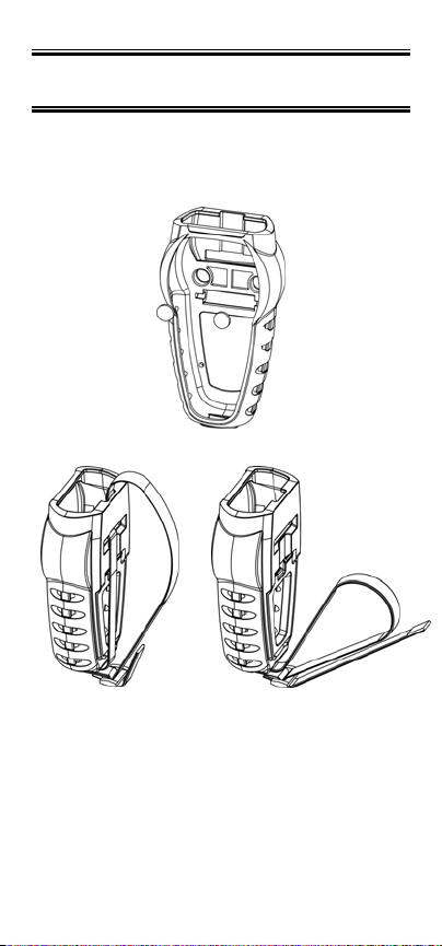
5. INSERTING AND REMOVING
OPTIONAL RUBBER ARMOUR
1. To insert thermometer into the
optional rubber armor, slide in from
the top of meter before pushing the
bottom edges of meter down to set it
into position. Lift up the stand at the
back of meter for bench top
applications if necessary.
2. To remove thermometer from armor,
push out from the bottom edges of
meter until it is completely out of boot.
- 7 -
Page 11
6. ASSEMBLING OPTIONAL
HANDSFREE ACCESORIES
You can use the optional magnets and
strap in the Handsfree Kit accessories for
hands free operations.
- 8 -
Page 12

7. CONNECTING A THERMOCOUPLE
Use
the
your instrume
incorr
erroneous
colour coded by type using
American
correct thermocouple type
ect th
ANSI
nt setting.
ermocouple
readi
ngs. T
Colour Code as
Using an
type
hermocouples are
for
will result in
th
e North
follows:
TYPE COLOR
J
Black
K Yello
T Blue
E Purple
Thermocouple connectors have one wide
blade and one narrow blade. Do not force
connector in backwards. Connect
thermocouples to receptacles at top of
instrument as shown in the following
illustration.
w
- 9 -
Page 13

Thermocouple wiring polarity must be
correct. If readings decrease as the
temperature increases, the thermocouple
wires may be reversed. The red wire is
negative for thermocouple wires
manufactured in North America.
If no probe is connected the display will
read “open”.
hermocouples are sensitive
T
measuring junction
,
measurements
to stabilize. Multip
of the
approx
probe by 5 will give you
imate time
allow
lying
required
at the tip or
. W
hen
time for the
taki
reading
the time constant
.
ng
the
- 10 -
Page 14

8. KEY FUNCTIONS
F1
F2 Choose probe T1, T2 or T1-T2
F3
hold Freeze display
on/off
light
recall▲
log▼
Note: Function keys change in setup
mode to provide advanced operation
flexibility. Text above key will indicate
function.
Step through Min, Max and
Avg readings.
Toggle between menu and
measure mode
Turns meter on and off (press
and hold for 3 seconds to turn
off)
Press momentarily to turn on
backlight
Recalls and steps through
stored readings
Stores current measured
value to memory
- 11 -
Page 15

9. DISPLAY OVERVIEW
1
7
6
5
2
3
4
The dot matrix display features a large
primary display, smaller secondary
displays for channel info or min/max/ave,
and helpful annuciators for added
measurement data
1 HOLD - Active
2 Data Logging is Active
3 Alarm Enabled – channel in alarm
indicated: T1 or T2 or T1&T2
4 MAX/MIN/AVG of Secondary
channel if MIN/MAX/AVG activated
5 MAX/MIN/AVG of Primary channel
if MIN/MAX/AVG activated
6 Min/Max hit time since Min/Max
activated. For Avg, it is continually
increments since activated
7 Current active Mode –
Min/Max/Avg
- 12 -
Page 16

10. MEASUREMENT MODE
On initial start-up the meter will display
the measured value for input one in the
primary display and for input two in the
secondary display.
F2
Pressing the
key will toggle primary
display through input one (T1), input two,
and the delta (T1 – T2) values.
F1
Pressing the
key initiates and toggles
through Minimum, Maximum, and
Average reading modes.
F3
Pressing
enter accesses Setup mode.
- 13 -
Page 17

11. HOLD FUNCTON
Press the hold key to retain the reading
on the display. Press the hold key again
for normal operation.
12. MIN, MAX, and AVE FUNCTION
Press the F1 key to toggle between the
minimum, maximum, and average
readings. The minimum and maximum
reading function is ideal for monitoring
unattended operations while continually
displaying every temperature change that
occurs. The minimum and maximum
values are sensed and automatically
stored.
To exit and clear this function, press the
F3 to access the Menu functions.
See the Clear Reset menu section for
more details.
13. DATA LOGGING
Press the
log
▼ key to store the current
reading to memory. The memory
indicator M = 1234 shows the memory
location for the next stored reading.
Press the
recall ▲
key to review stored
readings.
See section on Data Logging for timed
logging, and logging to a computer (300
model only).
See section on Clear/Reset for
information on clearing stored readings.
- 14 -
Page 18

14. SETUP MODE
To access the setup mode from
measurement mode press the F3 key
(Menu).
Press ▲▼ keys on the meter key pad to
scroll through options.
To enter a setup screen press Select
key.
To return to measurement mode press
F3
Meas
are listed
key. Following menu options
1. General Setup
2. User field calibration
3. Alarm settings
4. Data logging settings
5. View user calibration report
6. Clear/Reset options
- 15 -
F1
Page 19

15. GENERAL SETUP SCREEN
The first page of the General Setup
screens let you set probe type,
measurement units, time, and date.
Press F1 to indicate you want to change
the setting of the current parameter or
recall▲ or log▼ to move to the next
parameter.
Press recall▲ or log▼ to change the
options.
Press F2 to choose the next setting.
Whenever set the options, press F1 for
accepting the choice.
- 16 -
Page 20

On the second page you can set auto-off
time, line frequency, and password.
This screen below is used to reset/change
password. In the event if uses forget
his/her password, 5586 can be used to
reset to a new value
- 17 -
Page 21

16. CALIBRATION SCREEN
The thermometer is factory calibrated and
does not require calibration before use.
The Calibration function allows single
point calibration of the thermometer, at
0°C (32°F) to compensate for
thermocouple off-set error. It is NOT
necessary to perform a field calibration to
obtain specified meter accuracy. Use the
field calibration feature to improve
thermometer/probe accuracy or to
compensate for thermocouple drift.
..
Before go into the calibration mode, must
enter the password. Press F2 to change to
the next digit. (Default Password is 9900)
There are three calibration options:
Offset – adjusts at a single point
Slope – adjusts at two points
Match – adjusts readings on T1 to match
those on T2. Or adjusts T2 to match T1.
- 18 -
Page 22

Select calibration method by pressing F1
and the
▲ or ▼ keys.
channel you with to calibrate the
.
keys
Then select the
▲ or ▼
Offset Calibration
Use the ▲ or ▼ keys to adjust the value to
match known temperature standard. Press
F1 to accept.
- 19 -
Page 23

Slope Calibration
Use the ▲ or ▼ keys to adjust the value to
match known temperature standard. .
Press F1 to accept. Then move to second
temperature point using the ▲ or ▼ keys
and repeat.
Match Calibration
Use the ▲ or ▼ keys to adjust the value to
match T1 readings and T2 readings.
- 20 -
Page 24

17. ALARMS SCREEN
Disable or enable the alarm for individual
probe by pressing recall▲ or log▼and F1
to accept. Increase or decrease individual
limit by pressing recall▲ or log▼.
- 21 -
Page 25

18. DATA LOGGING SCREEN
Press recall▲ or log▼to choose the
logging methods as auto or manual. If it is
auto logging, using recall▲ or log▼to set
time interval. Its range is from 0min to
60min.
Button “Page1” will appear only in Temp
300.
Data Transfer from Meter to Computer
Model 300 only.
Please refer to softcopy of the driver
manual in the CD for installation and
datalogging instructions
- 22 -
Page 26

Once the USB connection is establish with
PC, press the Start button to download
data from Meter to PC using
HyperTerminal.
19. CALIBRATION REPORT SCREEN
The Calibration report will show the time
and date along with results of the last user
calibration.
- 23 -
Page 27

20. CLEAR / RESET SCREEN
Press F1 to choose which data you want
to clear or reset. For calibration, logged
data and reset all, you will have to enter
the password to proceed. (Default
Password is 9900)
- 24 -
Page 28

21. MAINTENANCE
Properly us
maintain calibr
require service
cleaning
ed, the th
ermome
ation indefinitely
other than
of the
housing and changing
ter
should
and
occasional
not
of
the batteries.
22. CLEANING
WARNING:
TO PREVENT IGNITION OF A
HAZARDOUS ATMOSPHERE BY
E
LEC
TROSTATIC DISCHARGE,
CLEAN WITH DAMP CLOTH.
Do
not
clean wi
Use mild
use excessive
23. BATTERIES
If there is no display when the
thermometer is turned on, check condition
of the three AA batteries. Also check that
the battery terminals are clean and
batteries are properly installed. If
replacement is necessary, refer to the
BATTERY INSTALLATION AND
REPLACEMENT section for replacement
procedure.
th
abrasives or solven
detergents,
fluid.
ts.
never immerse nor
- 25 -
Page 29

24. TROUBLE SHOOTING
The following chart lists the most probable
faults. There are no internal adjustments
or user-replaceable parts.
FAULT ACTION
NO
Display
Display
shows
- - - -
Display
Shows
OPEN
Display
Shows
Err
Check condition of batteries.
Check that batteries are inserted
properly.
Out of range indication
No thermocouple connected in the
Connector
If display shows this message
other than during the field
calibration mode, please return the
instrument for servicing
- 26 -
Page 30

25. ACCESSORIES
Replacem
Accessories
ent
Meters and Meter
Item Oakton Thermo Scientific
Type 100 thermometer 91427-40 TSTEMP100
Type 300 thermometer 91427-50
Rubber Armour with Stand
Handsfree Kit (Two Magnets
and a Strap)
General purpose probe
(immersion Into liquids), type
J
Penetration probe (meat,
semi-soft Materials), type J
Surface probe
(direct contact on
Hot surfaces), type J
Clip-on probe (surface
contacts- Electronics), type J
General purpose probe
(immersion Into liquids), type
K
Penetration probe (meat,
semi-soft Materials), type K
Surface probe
(direct contact on
Hot surfaces), type K
Clip-on probe (surface
contacts- Electronics), type
K
35427-80 ARMORTEMP
35427-85
08517-55
08517-65 EC-TPPENJ-
08517-60
08469-00 EC-TPCLPJ-
08516-55
08516-65 EC-TPPENK-
08516-60
08469-02
TSTEMP300
HNDSFRKIT
EC-TPGLPJ-
01M
01M
EC-TPSURJ-
01M
01M
EC-TPGLPK-
01M
01M
EC-TPSURK-
01M
EC-TPCLPK-
01M
- 27 -
Page 31

26. WARRANTY
he
Manufacturer
T
free
to be
from significant deviations
from published
period
of
three years. If
adjus
tment
warranty period
corrected
due
as
Repair
period, or
at
to
misuse or abuse on your
deter
mined by
costs
those
misuse or abus
you
.
warra
nts this product
specifications
repair or
is necessary within
, the
problem will be
no charge
outside
resulting
e,
if it is not
the
Manufacture
the
warr
from
may be invoiced
for a
the
anty
prod
part
r.
uct
to
27. PRODUCT RETURN
To limit
seller or Manu
and shipping in
returning
outsi
retur
reason
protection, pack
it
Manufacturer will not be responsible for
damage resulting from careless or
insufficient packing.
charges and dela
the
de
of the
ning
the
for the
agai
nst
possible damage or
ys, contact the
fact
urer
for
structions
produ
before
ct,
either within or
warranty peri
produc
t,
please
return
. For
the
carefully and insure
author
od. W
state the
your
loss. The
ization
hen
- 28 -
Page 32

28. INNOCAL® CALIBRATION AND
REPAIR SERVICES
Optimum performance of your
temperature-measuring instrument is not
a timeless condition. To ensure quality
measurements, have your instrument
calibrated regularly. Trust InnoCal® to
satisfy your calibration and equipment
repair needs. With over a decade of
service, we've helped thousands of
customers meet ISO, FDA, EPA,
GLPs/cGMPs and other quality
standards.
Conformity*
ISO/IEC 17025:2005 accredited
NIST Handbook 150, 2000 Edition
ANSI/NCSL Z540-2-1997
NIST Technical Note 1297
ISO 9000:2000
Fast Service
Our substantial inventory of replacement
parts ensures a fast turnaround and
prevents costly downtime. Most
instruments serviced in five business
days!
Excellent Value
Get quality at a fair price. Our InnoCal®
NIST-traceable certificates offer
extensive test data on a broad range of
measurement parameters without
breaking the bank!
- 29 -
Page 33

Reliable Support
Trust in our free diagnostic support and
troubleshooting advice. Our factorytrained metrologists and technicians are
armed with years of experience and
extensive technical data.
Convenient Reminders
It’s so easy to keep your instruments
functioning properly. Based on your
requirements, InnoCal will send you a
reminder when it’s time to re-certify or
service your instrument.
We provide you with the documentation
you need to meet your most stringent
quality requirements for the control of
inspection, measuring, and test
equipment.
Certification includes certificate of
calibration with test data, including:
● description and identification of the
item certified
● condition of the item
● issue date
● identification of calibration procedure
● calibration date
● as found/as left test data (where
applicable)
● signature of technician
● statement of estimated uncertainty
● list of equipment used to perform
calibration (including their calibration
dates)
- 30 -
Page 34

With today's high quality standards such
as ISO 9000, certification is becoming
increasingly important. Traceability is not
a timeless condition. It must be verified
and maintained over the life of the
calibration to ensure the highest
accuracy possible. When you have your
calibration done by InnoCal, we will send
you an automatic reminder when it is
time to recalibrate your instrument.
Are your calibration certificates good
enough?
InnoCal surpasses the competition by
providing the most complete certificates
as required by NIST. All of our
certificates include measured data and
point-by-point measurement uncertainty,
and by request, we’ll provide test
accuracy and test uncertainty ratios at
no extra cost. Call us today and see why
InnoCal is The Choice of Quality.
* See our Scope of Accreditation for any
limitations.
- 31 -
Page 35

Page 36

TECHNICAL ASSISTANCE
If
you have any questions abo
prod
of this
uct, contact the
Manufacturer or authorized se
ut the
ller.
use
For
more information on
OAKTON
Instruments Products, please contact
your nearest distributor or visit our web
site listed below:
OAKTON Instruments
P.O. Box 5136
Vernon Hills, IL 60061, USA Tel (in U.S.):
888-462-5866
Tel (outside U.S.) 1-847-549-7600
Fax: (1) 847-247-2984
Website: www.4oakton.com
E-mail:
info@oakton.com
Distributed by
:
 Loading...