

Page 1
Instruction Manual
gyM
sy...
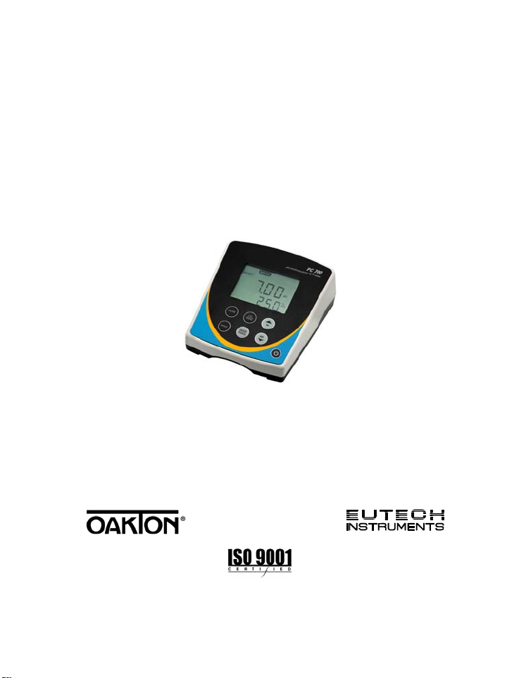
PC 700 pH/mV/Conductivity/ºC/ºF
Bench Meter
Part of Thermo Fisher Scientific 68X541704 Rev. 1 Feb. 2010
Tech nol o
adeEa
Find Quality Products On line at: [email protected]
www.GlobalTestSupply.com
Page 2

TABLE OF CONTENTS
1. INTRODUCTION.............................................................. 1
2. GETTING STARTED........................................................ 2
2.1 Keypad Functions ...................................................................2
2.2 LCD Annunciators ................................................................... 3
2.3 Meter Connections .................................................................. 3
3. CONDUCTIVITY ELECTRODE ....................................... 4
4. PH AND MV CALIBRATION............................................ 4
4.1 pH Calibration .........................................................................4
4.2 Millivolt (mV) Offset Adjustment ..............................................6
5. CONDUCTIVITY AND TDS CALIBRATION.................... 6
5.1 Automatic or Manual Calibration ............................................. 6
5.2 Single or Multi-Point Calibration.............................................. 7
5.3 General Calibration Tips .........................................................8
5.4 Automatic Conductivity Calibration Procedure ........................ 8
5.5 Manual Conductivity & TDS Calibration Procedure................. 9
5.6 Temperature Calibration .........................................................9
6. CONDUCTIVITY AND TDS MEASUREMENT................ 10
6.1 Taking Measurements............................................................. 10
6.2 Automatic and Manual Ranging ..............................................10
7. HOLD FUNCTION............................................................ 11
8. STORING AND RECALLING DATA ............................... 11
9. SETUP FUNCTIONS........................................................ 12
9.1 1.0 CAL (Calibration)............................................................... 12
9.2 2.0 ELE (Electrode Information).............................................. 12
9.3 3.0 ConF (Configuration)......................................................... 13
9.4 3.1 rdY (Ready / Stability Indicator)......................................... 13
9.5 3.2 ºC ºF (Celsius or Fahrenheit) ............................................ 13
Find Quality Products On line at: [email protected]
www.GlobalTestSupply.com
Page 3

9.6 3.3 buFF (pH Buffers & Calibration Points)—pH only .............13
9.7 3.3 AtC (Auto Temp Compensation)—Con & TDS only .......... 13
9.8 3.4 tdS (TDS factor)—Con & TDS only ................................... 14
9.9 3.5 t.CO (Temperature Coefficient)—Con & TDS only............ 14
9.10 3.6 t.nr (Normalization Temperature in ºC)—Con & TDS only 14
9.11 3.7 ACAL (Auto Conductivity Calibration)—Con & TDS only ..15
9.12 3.8 SPC (Single Point Calibration)—Con & TDS only ............. 15
9.13 3.8 CELL (Nominal Cell Constant)—Con & TDS only ............. 15
9.14 4.0 rSt (Reset)......................................................................... 16
9.15 5.0 CLr (Clear Memory) ..........................................................16
10. CALCULATING TDS CONVERSION FACTOR.............. 17
11. CALCULATING TEMPERATURE COEFFICIENTS........ 18
12. REPLACEMENTS AND ACCESSORIES........................ 19
13. TROUBLESHOOTING GUIDE......................................... 20
14. SPECIFICATIONS............................................................ 22
15. WARRANTY..................................................................... 24
16. RETURN OF ITEMS......................................................... 25
Find Quality Products On line at: [email protected]
www.GlobalTestSupply.com
Page 4

1. INTRODUCTION
Thank you for purchasing our PC 700 series benchtop meter.
This microprocessor-based meter is economical and simple to
use. The design incorporates a large LCD for clear viewing, yet
offers a small footprint to conserve space.
The PC 700 measures pH, mV (ORP), conductivity, or TDS
simultaneously with temperature (ºC or ºF).
Each meter includes a convenient slide-out card for quick
reference. Also included is an electrode arm and metal bracket
which can be easily attached to the left or right side of the meter
according to your preference.
The PC 700 benchtop meter replaces our popular pH/CON 510
series meter that was introduced in 2000.
We take great pride in every instrument we manufacture
and hope this one serves you well.
1
Find Quality Products On line at: [email protected]
www.GlobalTestSupply.com
Page 5
2. GETTING STARTED
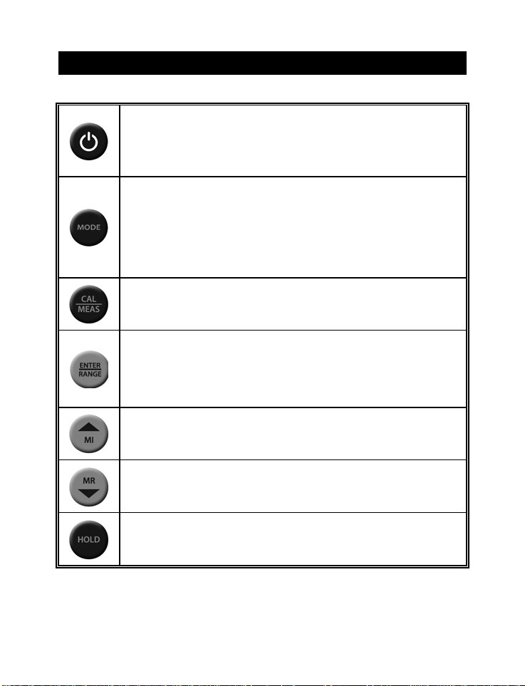
2.1 Keypad Functions
Powers the meter on and off. Upon power on, the meter
automatically begins in the mode that was last used.
Calibration and memory values are retained even if meter
is unplugged.
Toggle between available measurement modes—
pH/Temp, mV/Temp, Conductivity/Temp, or TDS/Temp.
Also used to switch to Temperature calibration during pH,
mV, Conductivity or TDS calibration modes.
Press and hold for 5 seconds to enter SETUP mode.
Toggles between measurement and calibration modes.
In SETUP mode, returns user to the measurement mode.
Confirms calibration values in CAL mode.
Confirms selections in SETUP mode.
Changes Con/TDS range and resolution in MEAS mode.
View recalled values in memory mode.
MI (Memory Insert) stores values into memory.
Increase value. Scroll up in SETUP & CAL modes.
MR (Memory Recall) recalls values from memory
Decrease value. Scroll down in SETUP & CAL modes.
Freezes measured reading. Press again to resume
live reading.
2
Find Quality Products On line at: [email protected]
www.GlobalTestSupply.com
Page 6
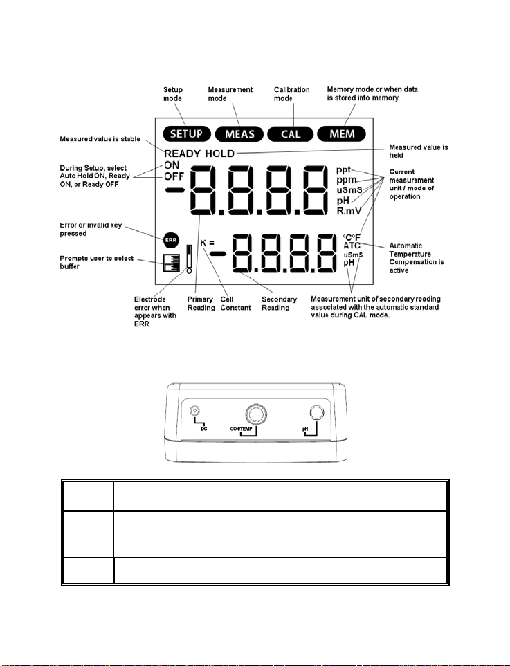
2.2 LCD Annunciators
2.3 Meter Connections
DC
CON/
TEMP
pH
Power supply
8-pin DIN connection for 2-cell Con/TDS/Temp electrode
BNC connection for pH, or ORP (Redox) electrode
3
Find Quality Products On line at: [email protected]
www.GlobalTestSupply.com
Page 7
3. CONDUCTIVITY ELECTRODE
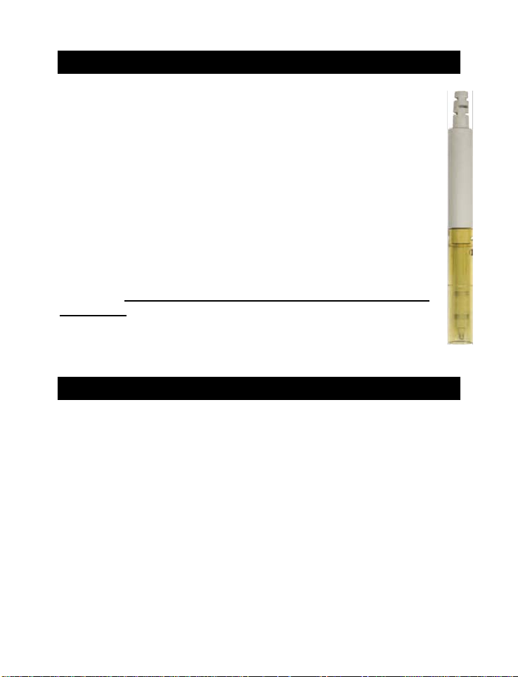
The PC 700 includes an electrode with a nominal cell constant of k
= 1.0, built-in temperature sensor, and 1 meter cable. The Ultem
body housing has good chemical resistant properties. The
electrode design offers fast temperature response and reduces air
entrapment, ensuring accurate, repeatable, and stable readings.
he wetted materials of the probe include:
T
Polyetherimide (Ultem) – protective probe guard
Polybutylterphalate (Valox) – sensor housing
Stainless Steel (SS 304) – 2 bands
The protective probe guard can be removed temporarily for
cleaning however it must be re-attached during measurement and
calibration. Erroneous results will occur while the probe guard
is removed.
Always immerse the probe beyond upper steel band for best
results. Use the fill line on the outside of the probe guard for
reference.
4. PH AND MV CALIBRATION
4.1 pH Calibration
For best results, periodic calibration with known accurate standards
recommended. Calibrate with standards that bracket your intended
measuring range while including a neutral standard (pH 7.00 or 6.86).
For example, if you expect to measure samples from
c
alibration with 4.01, 7.00, and 10.01 will work well.
The PC 700 meter can be calibrated with up to 5 buffers. The
non-vola
down.
The follo
tile memory retains all calibration values upon meter shut
wing calibration standards are automatically recognized;
pH 6.2 to pH 9.5,
is
4
Find Quality Products On line at: [email protected]
www.GlobalTestSupply.com
Page 8
USA buffer group 1.68, 4.01, 7.00, 10.01, 12.45
NI 5 ST buffer group 1.68, 4.01, 6.86, 9.18, 12.4
1) Press as needed to select pH.
e buffer group See Section 9.6 to change th
Dip the pH and ATC electrodes into pH buffer and press 2)
. The
secondary display will lock on the appropriate buffer value. Provide
ing for best results. When the READY indicator appears, prstirr ess
to accept. The primary reading will flash briefly before the
secondary display begins scrolling the remaining available buffers.
3) r.
Rinse the pH and ATC electrodes then dip into the next pH buffe
The secondary display will lock on the appro ate buffer value.
When the READY indicator appears, press
pri
to accept. The
primary reading will flash briefly then display the percent efficiency
(slope) before the secondary display begins scrolling the remaining
available buffers.
4)
To calibrate another buffer repeat step 3) or press
to return to
the measurement mode. Note: The meter will automatically return
to measurement mode upon successful completion of the numbe
specified calibration points. To spec
ify a different number of pH
calibration points see Section 9.6.
IPS: A single poT
int (offset) calibration is only allowed with pH 7.00 or
pH 6.86 buffers.
When the first calibration value is acce
ca
all prior libration values are erased.
ress P
at any time to abort calibration and return to measurement
pted during a new calibration,
mode.
r of
5
Find Quality Products On line at: [email protected]
www.GlobalTestSupply.com
Page 9
4.2 Millivolt (mV) Offset Adjustment
Oxidization Reduction Potential (ORP or Redox) is not a precise
measurement, but is useful as a relative indicator. As such, mV offset
adjustment is not meant to enhance accuracy, but rather to make
readings comparable to a reference. Commercial ORP solutions are
often used as a check s
verified to be close to a given value, instea of being used as a
calibration standard in which adjustments made in an attempt to
match the ORP value.
tandard in which a meter/electrode system are
d
are
nect an ORP electrode and press as needed to select
1) Con
(or R.mV).
2) Dip the ORP el
(i.e. Zobel, Light’s, quinhydrone, or iodidetriiodide) and stir.
3) Press when the reading is stable he prima display shows
the relative millivolt value (R.m ) whi he secon ry display sho
factory default mV value.
the
Adjust the R.mV value using
) or . Press 4 to accept or
to cancel. The meter allows an adjustable maximum value of
150± mV from the factory default mV value.
Note: When an offset has been stored successfully, R.mV replac
mV.
ectrode into a solution with a known mV value
. T ry
V le t da ws
mV
es
5. CONDUCTIVITY AND TDS CALIBRATION
5.1 Automatic or Manual Calibration
The PC 700 is capable of automatic or manual calibration for
conductivity, and manual calibration for TDS.
In the automatic calibration mode, the meter will automatically se
one of (4) conductivity calibration standard values depending on the
range and normalization temperature being used (TABLE 1).
lect
6
Find Quality Products On line at: [email protected]
www.GlobalTestSupply.com
Page 10
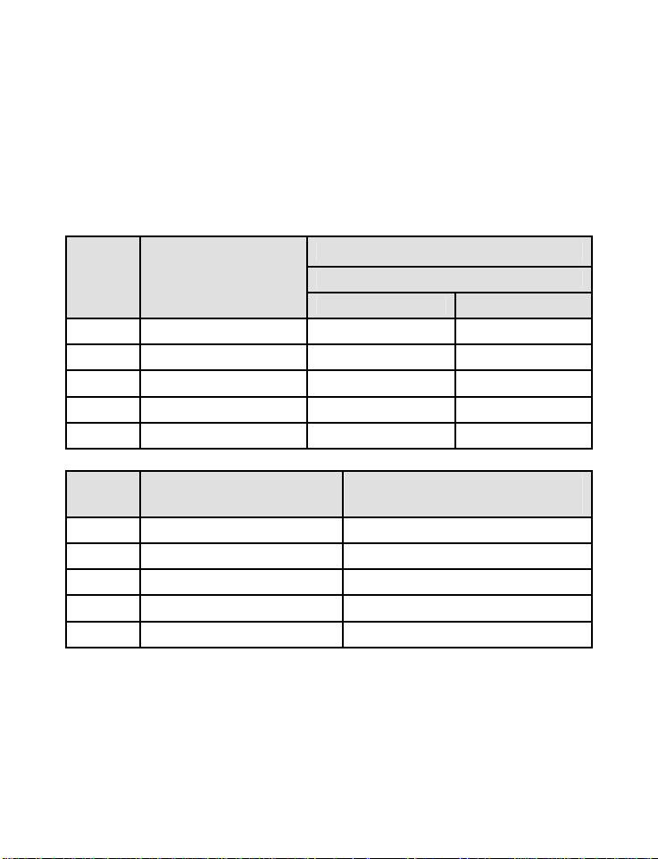
If you only use calibration standards that are listed in TABLE 1,
automatic calibration is recommended. If you intend to calibrate with
one or more standards that are not l
be set for manual calibration i
The factory default is automati
an ere i
ge this setting. Th
available
for e 1.
conductivity rang
isted in TABLE 1, the PC 700 must
nstead.
c conductivity calibration. See Section
s no automatic calibration value 9.11 to ch
TABLE
1
Auto Calibratio es matic n Valu
R e ang
#
r 1 0.00 – 20.00 μS None None
r 2 20.1 – 200.0 μS 84 μS 76 μS
r 3 201 – 2000 μS 1413 μS 1278 μS
r 4 2.01 – 20.00 mS 12.88 mS 11.67 mS
r 5 20. 111.8 mS 1 – 200.0 mS 102.1 mS
Conductivity
Range
N ation Temp ormaliz erature
25 ºC 20 ºC
Range
#
r 1 0 – 10.00 ppm none
r 2 1 0.1 – 100.0 ppm
r 3 101 – 1000 ppm
r 4 1.01 – 10.00 ppt
r 5 10.1 – 100 ppt
5.2 Single or Multi-Point Calibration
Use Single-Point Calibration to apply a single calibration value across
all ranges.
TDS Range
(us r) ing 0.5 TDS facto
Automatic Calibration
Values
none
none
none
none
7
Find Quality Products On line at: [email protected]
www.GlobalTestSupply.com
Page 11

Use Multi-Point Calibration for individual calibration in each range. T
ill restrict an individ
w
only. When using multi-point calib
range that you expect to use for b
ual calibration so that it is applied to one range
ration, perform a calibration in each
est results.
his
The factory default is Single-Point Calibration. See Section 9.12 to
change this setting.
5.3 General Calibration Tips
or best results, periodic calibration with known accurate standards is
F
recommended. A maximum of one calibrati
on point per range can be
performed. If multiple calibration points are used in the same range,
the most recent one will replace the previous one.
When the electrode is replaced, it is best to clear the calibration to the
factory default values (see Section 9.14).
Rinse or immerse the probe before
calibration and between samples
with clean water (deionized water is ideal).
The PC 700 has non-volatile memor
y which will retain all calibration
values, as well as meter settings and memory values upon meter shut
down or unexpected power loss.
To protect from erroneous calibrations, the allowable tolerance is ±40%
of the
factory default value.
Low conductivity standard solutions (less than 20 µS) ar
e unstable and
are very temperature dependent. As a result, reproducible calibration
results are challenging in lowest measurement range #1 (0.00
to 20.0
µS).
5.4 Automatic Conductivity Calib
ration Procedure
1) Press
as needed to select conductivity (μS or mS).
2) Dip the electrode into th . e conductivity standard and press
Provide stirring for best results.
3) The primary display will show the factory default value, while the
secondary display will lock on the appropriate automatic standard
value from TABLE 1.
8
Find Quality Products On line at: [email protected]
www.GlobalTestSupply.com
Page 12
4) When the READY indicator appears, press to accept. The
mode upon successful calibration.
5.5 Manual Conductivity & TDS Calibration Procedure
t primary reading will flash briefly before returning to measuremen
1) Press
as needed to select conductivity (μS or mS) or TDS
(ppm or ppt) calibration.
2) Dip the electrode into the calibration standard and press
.
Provide stirring for best results.
The primary display will show the current reading,3) while the
secondary display will be the factory default value. Adjust the
conductivity or TDS reading using or . Press to
accept. The primary reading will flash briefly before returning to
measurement mode upon successful calibration.
5.6 Temperature Calibration
The thermistor sensor used for automatic temperature compensation
and measurement is accurate and stable, so frequent calibration isn’t
req mended upon probe
uired. Temperature calibration is recom
replaceme whenever the temperature reading is suspect, or if
nt,
matching against a certified thermometer is desired.
1) n with a known accurate temperature
Place the probe into a solutio
such as a constant temperatur
2) Press
followed by . The primary display shows the
e bath.
measured temperature while the secondary display shows the
factory default temperature.
) Adjust the temperature using
4 or . Press to accept or
he meter allows a
º
( r ± 9 F) from the factory default temperature.
o
n adjustable maximum value of ± 5
º
C to cancel. T
9
Find Quality Products On line at: [email protected]
www.GlobalTestSupply.com
Page 13

6. CONDUCTIVITY AND TDS MEASUREMENT
6.1 Taking Measurements
1) Rinse the electrode with de-ionized or distilled water before use
to remove any impurities. Gently shake excess water droplets.
2) Dip the pro
(utilize the fill line on the out
reference).
3) Allow time for the reading to stabilize. Note the reading on the displa
The clear yellow protective probe guard must be attached durin
measurement. Erroneous results will occur while the probe guard is
removed.
6.2 Automatic and Manual Ranging
The PC 700 automatically selects the optimum range in which your
readings appear. Refer to TABLE 1 for a list of the available ranges.
be into the sample beyond the upper steel band
side of the probe guard for
y.
g
To turn-off automatic ranging, press
that manual ranging is active. To manually
press
again. After range 5, automatic ranging is resumed.
. MEAS will flash, indicating
select the next range,
F(ror example, a reading of 465 μS will automatically settle in range 3
3). Using manual range advancement this will read as 0.47 mS in
range 4 (r4), and 0.5 mS in range 5 (r5).
Automatic ranging is typically used since this will always provide the
best resolution.
10
Find Quality Products On line at: [email protected]
www.GlobalTestSupply.com
Page 14
7. HOLD FUNCTION
For prolonged observation of a reading, press during
measurement mode to freeze the display. The “HOLD” indicator will
display when the reading is held. To release the held value and
resume measurement, press
memory by pressing
.
again or insert the held value into
8. STORING AND RECALLING DATA
The PC 700 can retain up to 100 data points into memory for
later retrieval.
1) In the measurement mode, press
into memory. The stored memory location value (StO) is briefly
displayed.
2) To recall data from memory, press
recent stored data is displayed first. Press or to select the
location of the desired data, then press to accept.
3) Press to return to the stored data location. Press to return
to measurement mode. To erase stored data, see Section 9.15.
to insert the measured value
. The location of the most
11
Find Quality Products On line at: [email protected]
www.GlobalTestSupply.com
Page 15
9. SETUP FUNCTIONS
Use the setup feature to customize your instrument operation. First,
select the appropriate measurement mode you wish to adjust by
pressing
Conductivity, or TDS). During measurement, press and hold
seconds to enter SETUP mode of the parameter being measured.
Press
Press to select the program or confirm selection.
Press
9.1 1.0 CAL (Calibration)
9.2 2.0 ELE (Electrode Information)
TIP: When multiple pH slopes exist, the slope that is available to view
will depend on the measured value before entering SETUP mode.
For example, if pH calibration values pH 4.01, 7.00 and 10.01 were
completed, there will be two slope values; one that corresponds to pH
values below 7.00 and another that corresponds to pH values above
7.00. If the measured pH value was 5.23 when setup mode was
entered, the pH slope that corresponds to values lower than 7.00 will
be available to view. If no calibration is stored, the offset will be 0.0
mV and the slope is 100%.
until the desired units are displayed (i.e. pH, mV,
or to change programs or change options.
to go back one level or return to measurement mode.
Press
Press
Press to view % slope (SLP)—pH mode.
Press
and TDS modes.
to view stored calibration points.
to view mV offset (OFS)—mV and pH modes.
to view cell efficiency in each range—conductivity
12
for 5
Find Quality Products On line at: [email protected]
www.GlobalTestSupply.com
Page 16
9.3 3.0 ConF (Configuration
)
Press
to access set-up programs 3.1 thru 3.9.
3.19.4 rdY (Ready / Stability Indicator)
Press
.
Press or to choose READY “On”, READY “OFF”, or
Auto HOLd.
Press
to confirm.
9.5 3.2 enheit) ºC ºF (Celsius or Fahr
Press
.
Press or to select ºC or ºF.
Press to confirm.
.6 3.3 buFF (pH Buffers & Calibration Points)—pH only 9
Press
.
Press or to select “USA” or “NIST” buffer group
de ly). (pH mo on
Press
or to select number of Calibration Points
(pH and Ion only).
Press
to confirm.
AtC (Auto Temp Com9.7 3.3 pensation)—Con & TDS only
Press
.
13
Find Quality Products On line at: [email protected]
www.GlobalTestSupply.com
Page 17
Press or to select “Yes” or “No”.
Press to confirm.
9.8 3.4 n & TDS only
tdS (TDS factor)—Co
ress
P
.
Press or to select the desired TDS factor (.40 to
1.00).
Press
to confirm.
9.9 3.5 t.CO (Temp efficient)—Con & TDS only
The tem c e amount of change in conductivity per
erature oefficient is thp
erature Co
degree temperature (% per ºC). The PC 700 is factory set to a
temperature coefficient of 2.1 % per ºC. For most applications t
his will
provide good results. The meter allows adjustment from 0.0 to 10.0.
TIP: Select 0.0% for uncompensated measurements. The temperature
will be measured by the electrode and displayed in measurement
mode—without compensation.
See Section 11 – Calculating Temperature Coefficients.
Press
.
Press or to select the desired value (0.00 to 10.0).
Press to confirm.
9.10 3.6 t.nr (Normalization Tempera
When Au ompensation is used, measurements
tomatic Temperature C
ture in ºC)—Con & TDS only
are adjusted by the temperature coefficient to the normalization
temperature. The default value is 25 ºC.
14
Find Quality Products On line at: [email protected]
www.GlobalTestSupply.com
Page 18
Press .
Press or to select the desired value (15.0 to 30
Press
to confirm.
.0).
ACAL to nductivity Calibration)—Con & TDS
3.7 (Au Co
See Sectio for more deta atic Conductivity Calibration.
n 5.1 ils on Autom
ress
. P
only9.11
Press or to select “Yes” (Automatic) or “No” (Manual).
Press to confirm.
9.12 3.8 Po
See Sectio for details o
SPC (Single int Calibration)—Con & TDS only
n 5.2
ress
. P
n Single Point & Multi Point Calibration.
Press or to select “Yes” (Single) or “No” (Multi).
Press to confirm.
9.13 3.8 No al
CELL ( min Cell Constant)—Con & TDS only
The PC 700 includes a probe with a nominal cell constant (k) of 1.0.
Use prob k parately) for improved
performa ce in extreme sample ranges. Use this setup function to
change the cell constant if necessary. Meter default is 1.0 to m
es with = 0.1 and 10 (sold se
n
atch the
included probe.
k = 0.1 ideal for low measurements <20 µS (<10 ppm).
k = 1.0 ideal for mid-range measurements
k = 10 ideal for high measurements >20 mS (>10 ppt).
Press
.
Press or to select 0.1, 1.0, or 10.0
Press to confirm.
15
Find Quality Products On line at: [email protected]
www.GlobalTestSupply.com
Page 19
9.14 4.0 rSt (Reset)
. Press
or Press to select “Yes” (Reset) or “No” (Cancel).
sIf “Yes”, pres or to select “Cal” (calibration reset
ete reset to factory default settings). only) or “FCt” (compl
Press
9.15 5.0 o
CLr (Clear Mem ry)
Press
Press or to select “Yes” (Erase memory) or “No”.
Press to confirm.
to confirm.
.
16
Find Quality Products On line at: [email protected]
www.GlobalTestSupply.com
Page 20

10. CALCULATING TDS CONVERSION FACTOR
You can calibrate TDS using the value of the calibration standard solution
at a standard temperature such as 25 ºC. To determine the conductivityto-TDS conversion factor use the following formula:
Factor = Actual TDS ÷ Actual Conductivity @ 25 ºC
Actual TDS: Value from the solution bottle label or as a
standard made using high purity water and precisely weighed
salts.
ppm = milligram of salt(s) per liter of water = mg/L
ppt = gram of salt(s) per liter of water = g/L
Actual Conductivity: Value measured using a properly
calibrated Conductivity/Temperature meter.
Both the Actual TDS and the Actual Conductivity values must be in the
same magnitude of units. For example, if the TDS value is in ppm the
conductivity value must be in µS; if the TDS value is in ppt the conductivity
value must be in mS.
Check your factor by multiplying the conductivity reading by the factor in
the above formula. The result should be in TDS value.
When the TDS factor is set to 1.0, Conductivity = TDS.
17
Find Quality Products On line at: [email protected]
www.GlobalTestSupply.com
Page 21

11. CALCULATING TEMPERATURE COEFFICIENTS
To determine the temperature coefficient of your sample solution use this
formula:
Where:
tc = Temperature coefficient 25 = 25 ºC
C
= Conductivity at Temp 1 CT2 = Conductivity at Temp 2
T1
T1 = Temp 1 T2 = Temp 2
NOTE: A controlled temperature water bath is ideal for this procedure.
1. Immerse the probe into a sample of your solution and adjust the
temperature coefficient to 0% (that is, no compensation) by following
instructions as described in Section 9.9.
2. Wait for 5 minutes. Note T1 and CT1 (conductivity at T1).
3. Condition the sample solution and probe to a temperature (T2) that is
about 5 ºC to 10 ºC different from T1, and note the conductivity
reading C
.
T2
NOTE: Record your results for future reference. Ideally T1 and T2 should
bracket your measurement temperature, and should not differ by
more than 5 ºC.
4. Calculate the temperature coefficient of your solution according to the
formula shown above.
5. Enter the calculated temperature coefficient into the meter.
The calculated temperature coefficient will now be applied to all the meter
readings.
18
Find Quality Products On line at: [email protected]
www.GlobalTestSupply.com
Page 22
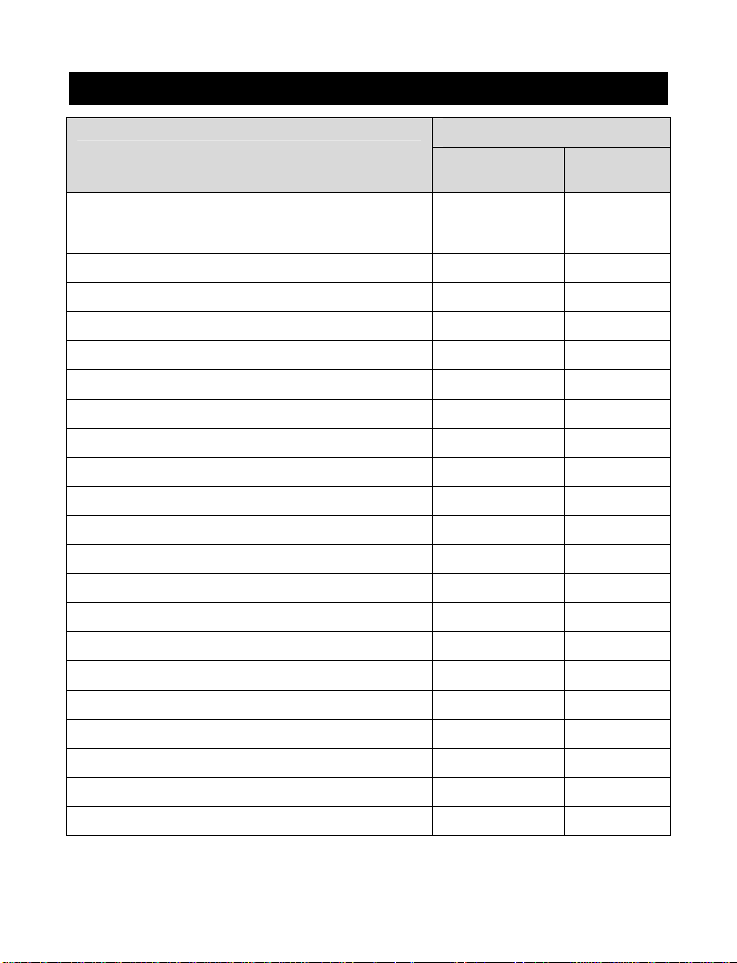
12. REPLACEMENTS AND ACCESSORIES
Part number Ordering Code
Item Description
PC 700 with pH electrode (ECFC7252101B / 59001-
70), conductivity/temp electrode (CONSEN9501D /
35608-74), integral stand,100/240 VAC
PC 700 with integral stand, 100/240 VAC - 35413-20
Plastic, Gel-filled, Double-junction pH electrode ECFC7252201B 35641-51
Plastic, Gel-filled, Single-junction pH electrode ECFC7252101B 59001-70
Replacement conductivity/temp electrode, k = 1.0 CONSEN9501D 35608-74
Epoxy/platinum conductivity/temp electrode, k = 0.1 - 35608-72
Glass/platinum conductivity/temp electrode, k = 1.0 - 35608-76
Epoxy/platinum conductivity/temp electrode, k = 10.0 - 35608-78
SMPS, 100/240 VAC, 9V, 6W power adapter 60X030130 35615-07
10 μS, (20) x 20mL Sachets ECCON10BS 35653-09
84 µS, 480 mL bottle* ECCON84BT 00653-16
447 μS, 480 mL bottle ECCON447BS 00653-47
500 μS, 480 mL bottle ECCON500BT -
1413 μS, 480 mL bottle* ECCON1413BT 00653-18
1413 μS, (20) x 20mL Sachets* ECCON1413BS 35653-11
2764 μS, 480 mL bottle ECCON2764BT 00653-20
2764 μS, (20) x 20mL Sachets ECCON2764BS 35653-12
5.0 mS, 480 mL bottle ECCON5000BT -
12.88 mS, 480 mL bottle* ECCON1288BT 00606-10
15 mS, (20) x 20mL Sachets ECCON15000BS 35653-13
111.8 mS, 480 mL bottle* ECCON1118BT -
*Automatic Calibration Standard Value at 25 ºC
Eutech
Instruments
ECPC70043S
01X543601
Oakton
Instruments
35413-00
19
Find Quality Products On line at: [email protected]
www.GlobalTestSupply.com
Page 23
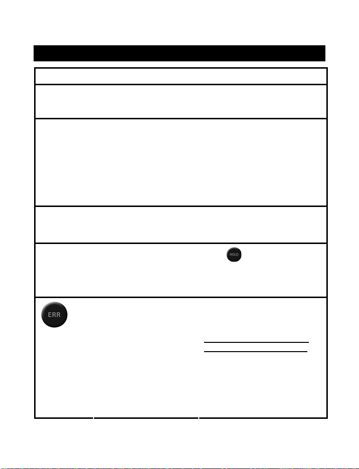
13. TROUBLESHOOTING GUIDE
PROBLEM CAUSE SOLUTION
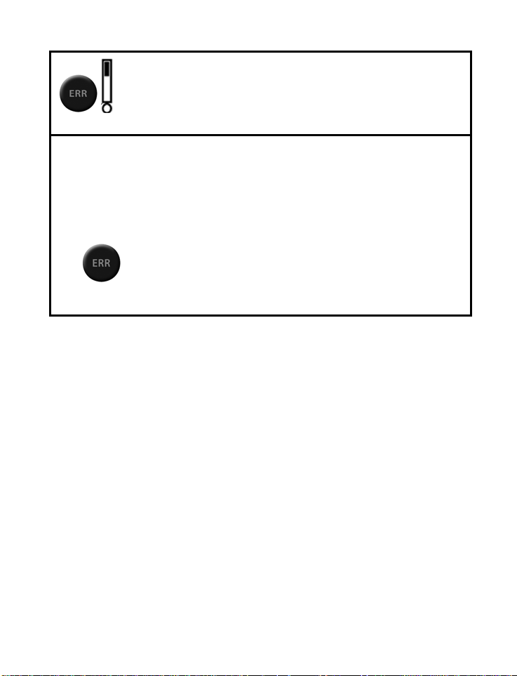
No display Main power not switched
“Ur” (Under
range)
“Or” (Over
range)
in primary or
secondary
display
Slow
response
Meter not
responding to
key press
Secondary
display
continually
scrolls
on. AC Adapter socket not
inserted properly.
Measured value is out
of range.
Electrode not connected.
Electrode clogged, dirty
or broken.
Meter not calibrated.
Wrong temp value.
Dirty electrode.
Temperature of sample is
changing.
Manual HOLD or Auto
HOLD is active.
Worn keypad.
Invalid key; Button is not
functional in the current
operation mode.
The conductivity calibration
standard is not within 40%
of expected value during
automatic calibration.
The pH buffer is >1 pH unit
from the available pH
buffers remaining for
calibration.
Switch on the power supply.
Re-insert AC Adapter.
Check electrode is connected.
Clean or replace electrode.
Recalibrate the meter.
Confirm measurement condition.
Treat samples to bring within
meter measuring range.
Reset meter.
Clean the electrode.
Allow temperature to stabilize.
Press
HOLD. See Section 9.4 to disable
Auto Hold feature if enabled.
Contact Technical Service.
Press alternate key.
Select valid key depending on
current mode.
Ensure that the conductivity
electrode guard is attached.
Use fresh standard or use an
alternate calibration standard.
Use fresh standard or use an
alternate calibration standard.
Verify the USA or NIST buffer
selection. Check pH electrode.
to deactivate manual
20
Find Quality Products On line at: [email protected]
www.GlobalTestSupply.com
Page 24
reading
Slow
response
CAL
during pH
CAL mode
Calibration error.
Buffer value does not
match displayed value or
electrode is disconnected
or failing.
Broken or worn electrode Replace electrode Unstable pH
External ‘noises’ or
induction (electrical ‘noise’
caused by a nearby motor)
Dirty electrode. Clean & rehydrate the electrode
Calibration was attempted
using only 1-point that was
not pH 7 (USA) or pH 6.86
(NIST).
Use fresh buffer solutions.
Check electrode connection.
Clean & recondition electrode.
Replace electrode.
Remove or switch off interfering
device
Recalibrate using 2 or more pH
points or use pH 7 (USA)
or use pH 6.86 (NIST).
21
Find Quality Products On line at: [email protected]
www.GlobalTestSupply.com
Page 25
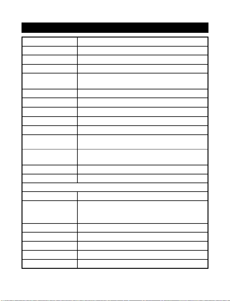
14. SPECIFICATIONS
pH Range 0.00 to 14.00 pH
Resolution 0.01 pH
Accuracy
Calibration Points Up to 5 points with Auto-buffer recognition
Buffer Options
Slope Display Yes (with offset)
mV Range
Resolution
Accuracy
Offset Adjustment Up to ±150 mV
Conductivity Range
TDS Range
(0.5 TDS factor)
Resolution 0.05 % Full Scale
Accuracy ±1% Full Scale
Temperature
Range (Meter) 0.0 to 100.0 ºC / 32.0 to 212.0 ºF
Compensation
Type & Range
Resolution 0.1 ºC / ºF
Accuracy ± 0.5ºC / ± 0.9ºF
Calibration
Coefficient 0.0 to 10.0% per ºC
Normalization 15.0 to 30.0 ºC (adjustable)
0 to 10.00, 100.0 ppt
USA : pH 1.68, 4.01, 7.00, 10.01,12.45
NIST: pH 1.68, 4.01, 6.86, 9.18 ,12.45
0.1 mV ( 199.9 mV), 1 mV beyond 200 mV
0.2 mV ( 199.9 mV), 2 mV beyond 200 mV
Automatic with supplied cell or Manual.
0.0 to 80 ºC / 32.0 to 176.0 ºF with supplied cell
Offset in 0.1 º increments; Offset range: 5 ºC / 9 ºF
0.01 pH + 1 count
2000 mV
0 to 20.00, 200.0, 2000 µS
0 to 20.00, 200.0 mS
0 to 10.00, 100.0, 1000 ppm
(max 200.0 ppt @ 1.0 TDS factor)
0.0 to 100 ºC / 32.0 to 212.0 ºF,
22
Find Quality Products On line at: [email protected]
www.GlobalTestSupply.com
Page 26
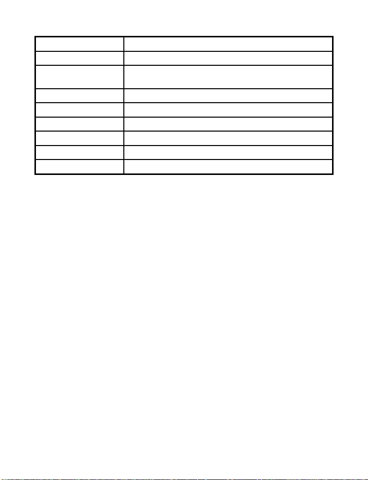
Cell Constant 0.1, 1.0, 10.0 (selectable)
TDS Factor 0.40 to 1.00 (adjustable)
Calibration points
Auto-ranging Yes
Hold Function Yes
Memory 100 data sets
Input BNC, 8-pin DIN
Power AC/DC 9V, 6W Adapter (100/240 VAC, 50-60Hz)
Dimensions (mm) meter only = 175 (L) x 155 (W) x 69 (H)
Automatic (4 points); Maximum 1 per range
Manual (5 points); Maximum 1 per range
23
Find Quality Products On line at: [email protected]
www.GlobalTestSupply.com
Page 27

15. WARRANTY
This meter is supplied with a warranty against significant deviations in
material and workmanship for a period of THREE years from date of
purchase whereas probe with a SIX month warranty.
If repair or adjustment is necessary and has not been the result of abuse
or misuse within the designated period, please return – freight prepaid –
and correction will be made without charge. Eutech Instruments/Oakton
Instruments will determine if the product problem is due to deviations or
customer misuse.
Out of warranty products will be repaired on a charged basis.
The warranty on your instrument shall not apply to defects resulting from:
Improper or inadequate maintenance by customer
Unauthorized modification or misuse
Operation outside of the environment specifications of
the products
24
Find Quality Products On line at: [email protected]
www.GlobalTestSupply.com
Page 28

16. RETURN OF ITEMS
Authorization must be obtained from our Customer Service Department or
authorized distributor before returning items for any reason. A “Return
Material Authorization” (RMA) form is available through our authorized
distributor. Please include data regarding the reason the items are to be
returned. For your protection, items must be carefully packed to prevent
damage in shipment and insured against possible damage or loss.
Eutech Instruments will not be responsible for damage resulting from
careless or insufficient packing. A restocking charge will be made on all
unauthorized returns.
NOTE: Eutech Instruments Pte Ltd /Oakton Instruments reserve the right
to make improvements in design, construction, and appearance of
products without notice.
25
Find Quality Products On line at: [email protected]
www.GlobalTestSupply.com
 Loading...