

Page 1
TechnologyMadeEasy...
Part of Thermo Fisher Scientific 68X544001 Rev 2 Apr 2013
Instruction Manual
2700 Series
Benchtop Meters
pH 2700 ● ION 2700 ● CON 2700 ● DO 2700 ● PC 2700
www.GlobalTestSupply.com
Page 2

TABLE OF CONTENTS
1. Introduction ...................................................................................... 1
2. Getting Started ................................................................................. 2
Keypad and Display ................................................................................................ 2
Navigation of Tabs .................................................................................................. 3
Meter Connections ................................................................................................. 4
3. System Setup & Configuration ....................................................... 5
Stability ................................................................................................................... 5
Stability Criteria ...................................................................................................... 6
Auto Read ............................................................................................................... 6
Print Set ................................................................................................................... 7
Date & Time ............................................................................................................. 8
Password ................................................................................................................ 8
Clear Datalog .......................................................................................................... 8
Factory Reset .......................................................................................................... 9
Contrast Adjustment .............................................................................................. 9
4. Setup pH & mV ................................................................................. 10
Sample ID ................................................................................................................ 10
Buffer (Group Selection) ........................................................................................ 10
Cal Points ................................................................................................................ 11
Resolution ............................................................................................................... 11
Alarm ....................................................................................................................... 11
Cal Due .................................................................................................................... 11
5. pH Calibration (with preset buffer group) ..................................... 12
6. pH Calibration (with custom buffers) ............................................ 14
7. Millivolt (mV) Calibration (Offset Adjustment) .............................. 16
8. Temperature Setup .......................................................................... 17
9. Temperature Calibration ................................................................. 18
10. Conductivity, TDS, Salinity, & Resistivity Setup .......................... 19
Sample ID ................................................................................................................ 19
Cal Points ................................................................................................................ 20
Pure Water Coefficient ........................................................................................... 20
Temperature Coefficient (linear) ............................................................................ 20
Normalization Temperature (°C) ............................................................................ 21
Cell Constant .......................................................................................................... 21
Alarm ....................................................................................................................... 22
Cal Due .................................................................................................................... 22
11. Conductivity Calibration (automatic) ............................................. 23
12. Conductivity, TDS, Salinity, & Resistivity Calibration (manual
adjustment) ............................................................................................. 25
www.GlobalTestSupply.com
Page 3

13. Ion Setup .......................................................................................... 27
Sample ID ................................................................................................................ 27
Measure Unit ........................................................................................................... 27
Alarm ....................................................................................................................... 27
Cal Due .................................................................................................................... 28
14. Ion Calibration .................................................................................. 29
15. Dissolved Oxygen Setup ................................................................ 31
Sample ID ................................................................................................................ 31
Offset Cal (% saturation only) ................................................................................ 31
Pressure Unit (% saturation mode only) ............................................................... 31
Pressure Cal (% saturation mode only) ................................................................. 32
Pressure Compensation (% saturation mode only) .............................................. 32
Measure Unit (concentration mode only) .............................................................. 32
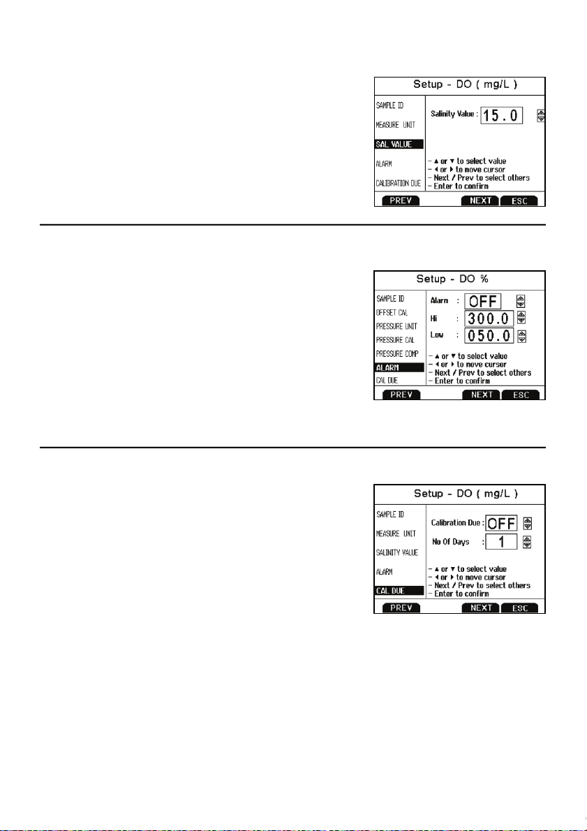
Salinity Value (concentration mode only) ............................................................. 33
Alarm ....................................................................................................................... 33
Cal Due .................................................................................................................... 33
16. Dissolved Oxygen Calibration ........................................................ 34
100 % Calibration .................................................................................................... 34
0% Calibration ......................................................................................................... 35
mg/L or ppm (Concentration) Calibration ............................................................. 35
17. Transferring and Printing Data ....................................................... 37
18. Calibration Report ........................................................................... 38
19. Dissolved Oxygen Theory .............................................................. 39
20. Calculating Temperature Coefficients ........................................... 42
21. Calculating TDS Conversion Factor .............................................. 43
22. DO Electrode Maintenance ............................................................. 44
23. Troubleshooting .............................................................................. 45
24. Specifications .................................................................................. 47
25. Replacements and Accessories ..................................................... 50
26. Warranty ........................................................................................... 52
27. Return of Items ................................................................................ 53
www.GlobalTestSupply.com
Page 4
1
1. Introduction
If you are viewing an electronic version of this manual, you
Thank you for selecting our 2700 series research benchtop meter. This
microprocessor-based instrument incorporates a large LCD for clear viewing, yet
offers a small footprint to conserve space.
Each meter includes a convenient slide-out calibration card for quick reference. All
models (except for DO 2700) include an electrode arm and metal bracket which
can be easily attached to the left or right side of the meter according to your
preference.
The 2700 series benchtop meter replaces our popular 1100 and 2100 series
meters that were introduced in 2001.
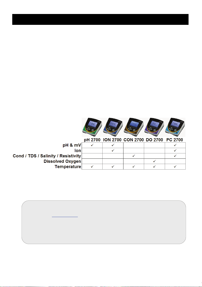
Please note that this manual serves all 2700 models, so not all sections of the
manual will be relevant to each model. The chart below lists the parameters
served for the various models:
We take great pride in every instrument we manufacture and hope this one
serves you well.
can use hyperlinks located in the Table of Contents and
elsewhere by holding down the CTRL key as you click the
hyperlink.
Find other helpful tips listed in grey boxes like this one!
www.GlobalTestSupply.com
Page 5
2
2. Getting Started
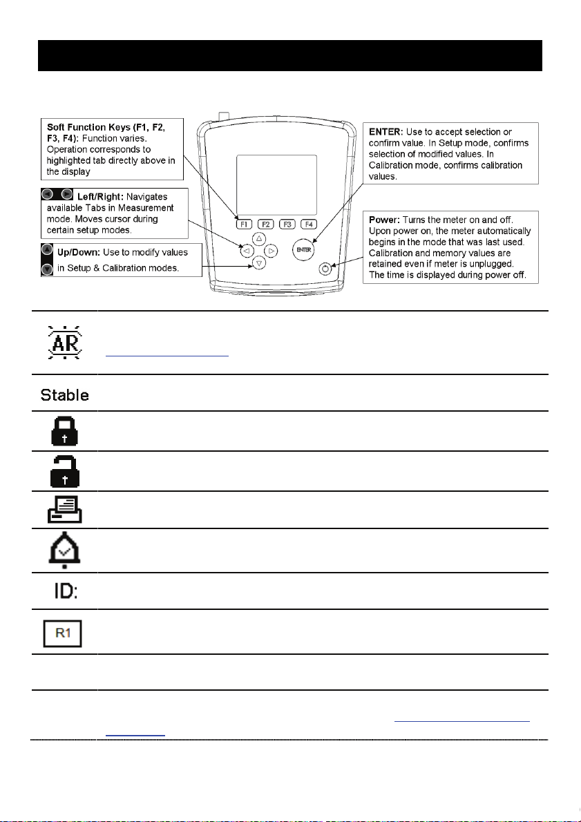
Auto Read is enabled. When flashing, the instrument has detected a ‘Stable’
SETUP…SYSTEM…AUTO READ.
acquired with attached electrode. ATC is recommended.
Manual Temperature Compensation is active. A temperature sensor may not
Calibration to calibrate the ATC or MTC temperature values.
Keypad and Display
reading and locked the value. Press MEAS to resume live reading. See
Section 3—Auto Read to disable this feature, or go to
Based on the stability criteria settings in System Setup, the instrument has
detected a stable reading.
Password Protection: Enabled. Requires password for all
calibration and setup menus
Password Protection: Disabled. No password required for any menu.
Print Setting Timed interval is active; data is being output at regular intervals.
“High Alarm”, “Low Alarm”, or “Cal Due” alarm limit had been reached.
High/Low alarms also have an audible notification..
Sample ID: User selectable five digit number to identify samples.
Measuring Range # of displayed value (1 thru 5). Applicable to Conductivity,
TDS, Salinity, or Resistivity measurements only
(ATC)
(MTC)
Automatic Temperature Compensation is active; temperature is being actively
be attached so the default temperature is used. See Section 9—Temperature
www.GlobalTestSupply.com
Page 6
3
Navigation of Tabs
www.GlobalTestSupply.com
Page 7
4
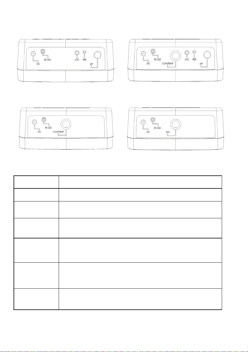
Meter Connections
DC
RS-232
CON/TEMP
DO
ATC
pH 2700
ION 2700
PC 2700
CON 2700 DO 2700
Power supply
RS-232 output, 2.5 mm jack for RS-232 cable
8-pin DIN connection for 2-cell or 4-cell Con/TDS/Temp
electrodes
8-pin DIN connection for Dissolved Oxygen/Temp self stirring
electrode
For Automatic Temperature Compensation probe.
For PC 2700, this corresponds to the temperature
measurement associated with the BNC (“pH”) input.
Pin connection for half cell reference electrodes.
REF
pH
Requires separate half cell electrode in the BNC (“pH”) input.
Note: REF is not commonly used and is not required.
BNC connection for combination pH, ORP (Redox), or Ion
Selective Electrodes (ISE), or half-cell indicating electrodes.
www.GlobalTestSupply.com
Page 8
5
3. System Setup & Configuration
STABILITY
PRINT SET
STABILITY
AUTO READ
PASSWORD
BACKLIGHT
CLEAR DATALOG
DATALOG
FACTORY RESET
PRINT SETUP
CONTRAST
PRINT FORMAT
Use the System Setup to customize operation of your 2700 series meter.
Press
SYSTEM is highlighted to access these settings.
The following settings can be customized for each model:
from the measurement screen and then press ENTER when
CRITERIA
DATE & TIME
Stability
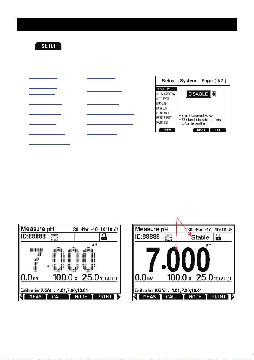
To aid with measurement and calibration, your meter has a unique feature that
provides an obvious visual indication when the reading becomes stable. If the
Stability feature is enabled, the digits on the primary reading will be faded when
unstable, becoming solid when stable. If this feature is disabled, the primary
reading will always be solid. The image below on the left is an unstable reading
during pH Measurement mode with Stability enabled. The image on the right
shows a stable reading.
www.GlobalTestSupply.com
Page 9

6
Stability Criteria
The 2700 allows adjustment of the Stable indicator which relates to how fast and
frequent it appears. There are three levels of adjustment; SLOW, MEDIUM, &
FAST.
To display a ‘Stable’ reading more quickly and more often, use “FAST” setting.
MEDIUM or SLOW is recommended for most applications. When Auto Read is
enabled, a stability criteria setting of “SLOW” is recommended to for best results.
SLOW: The Stable indicator will take longer to appear and will appear less
frequently. Use this setting if you want the best results and don’t mind waiting
longer to get them.
MEDIUM: This is the factory default setting. It provides a balanced response
which works best for most applications.
FAST: The Stable indicator will appear quickest of any setting. If you find that the
Stable indicator frequently appears and disappears, you may want to select a
slower setting. This setting is not recommended when AUTO READ is enabled. It
is also not suitable for most non-refillable electrodes which are generally slower to
respond.
Auto Read
If AUTO READ is enabled, the measured value will automatically lock
when the Stable indicator appears. A flashing “AR” icon confirms this
condition. To resume a live reading again, it is necessary to press MEAS
each time Stable appears. Disable this feature to continuously view the active
reading.
Backlight
Select “PERMANENTLY ON” on to keep the backlight on at all times that the
meter is powered on. This will offer the best visibility but consumes the most
power.
Select “ON WITH KEY PRESS” to turn on the backlight for a specified time after
any key press. Select “0” to keep the backlight off at all times that the meter is
powered on.
www.GlobalTestSupply.com
Page 10

7
Data Log (storing data to internal memory)
Select “SINGLE” to manually save one point at a time. Press the “MEM IN”
function key any time during measurement to save data.
Select “TIMED” to automatically save data at selectable intervals— ranging from
3 to 3600 seconds. Data will be collected until the data limit is reached or until
“SINGLE” data log is selected. This feature is useful for gathering data from a
single sample over time. Note that “MEM IN” is not available during TIMED
setting. As data is collected, the display will indicate how much memory has been
used.
To view stored data, use “MEM OUT”. Note: the more data that has been
acquired memory, the longer the data will take to display.
Print Setup
Adjust the RS-232 output settings for baud rate, parity, data bit, and stop bit to
match your printer or computer settings as necessary.
Print Format
When utilizing the RS-232 output; choose “TEXT/PRINTER” option to send the
data in an easily viewable format—best for printing.
Choose “CYBERCOMM” option to send the data as a comma separated value
(CSV)—best for exporting data into spreadsheet software.
Print Set
This is identical to the Data log function, but data is sent via RS-232 output
instead of internal memory.
Select “SINGLE” to manually output one value at a time—best for printing or
collecting data to your PC from many samples.
Select “TIMED” to automatically output live data at selectable intervals— ranging
from 3 to 3600 seconds. Data will be output until “SINGLE” Print set is selected.
This feature is most useful for gathering data for use with software. Unlike the
Data Log setting, data can be saved to memory using “MEM IN” during TIMED
setting.
www.GlobalTestSupply.com
Page 11

8
Date & Time
Setting the correct date and time is required for GLP and will apply to power off,
measurement, data log, and print functions. Instrument has battery backup to
retain date/time settings upon power loss. Factory reset will not apply to date and
time setting once it has been set. Changes related to daylight savings time must
be manually entered.
Date Format: Select (MM DD YY) or (DD MM YY)
Time Format: Select 12Hrs (AM/PM) or 24Hrs
Password
Select “ENABLE” to restrict access to Calibration and Setup modes. When
password protection is enabled, password entry is required before performing any
calibration, or making changes to the setup mode. Setup parameters can be
viewed, but can not be changed without correct password entry. The password is
a user selectable number from 1 to 99999.
Select “DISABLE” if password protection is not desired.
The meter does not allow you to edit setup parameters or perform a new
calibration unless you enter the correct password. If an incorrect password is
entered 3 consecutive times, the meter returns to measurement mode.
In the event the password can not be recovered, a password can be provided via
a written request to Eutech Instruments/Oakton Instruments. The instrument
serial number and your contact information are required.
Clear Datalog
Select “YES” to delete all saved data that was manually or automatically stored
into memory. This step is most commonly required when the “TIMED” data log
interval is not turned off and as a result, fills the memory to capacity. When the
memory is full, deleting the saved data is required in order to save additional
data/ The 2700 will never erase old data in favor of new data when the memory is
full.
If you wish to view, print or send the saved data to a PC before deleting, use the
“MEM OUT” function from measurement mode.
www.GlobalTestSupply.com
Page 12

9
Factory Reset
Select “YES” to reset the 2700 to the factory default settings except; Date & Time,
Temperature calibration, and data stored in memory.
Contrast Adjustment
Optimize the contrast setting of your 2700 display for best visibility in your
surrounding lighting conditions. Test various contrast settings for best results.
This setting will be applied to both backlight and non-backlight conditions.
www.GlobalTestSupply.com
Page 13
10
4. Setup pH & mV
Use Setup pH or mV mode to customize these parameters. Note: mV setup offers
Sample ID and Alarm setting only.
Press
or mV is selected.
from the measurement screen and then press ENTER when pH
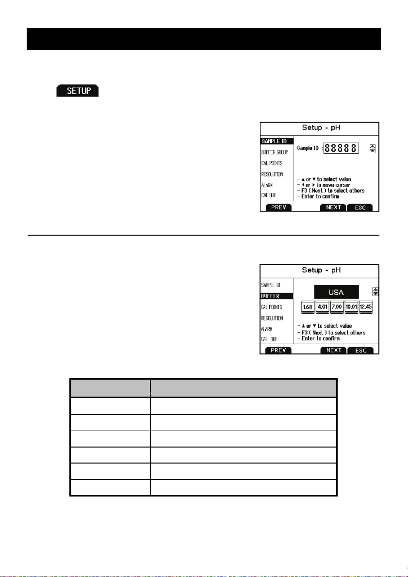
Sample ID
This is a user selectable number from 1 to 99999.
Incorporating a sample ID to identify one or more
data points is useful to distinguish data that is
saved into memory or sent to a PC or printer. Use
the up/down arrow keys to adjust the values and
left/right arrow keys to move the cursor.
Buffer (Group Selection)
Choose one of (6) pH buffer groups for calibration;
USA, NIST, DIN, USER 1, USER 2, and CUSTOM.
The pH values in the selected buffer group are
used for auto-recognition during pH calibration.
Choose the appropriate buffer group, based on the
pH calibration standards you intend to use.
Buffer Group pH Values
USA
NIST
DIN
USER 1
USER 2
CUSTOM Any 2 - 5 values, ≥ 1.0 pH unit apart
1.68, 4.01, 7.00*, 10.01, 12.45
1.68, 4.01, 6.86*, 9.18, 12.45
1.09, 3.06, 4.65, 6.79*, 9.23, 12.75
1.68, 4.01, 7.00*, 9.18, 12.45
1.68, 4.01, 6.86*, 10.01, 12.45
www.GlobalTestSupply.com
Page 14
11
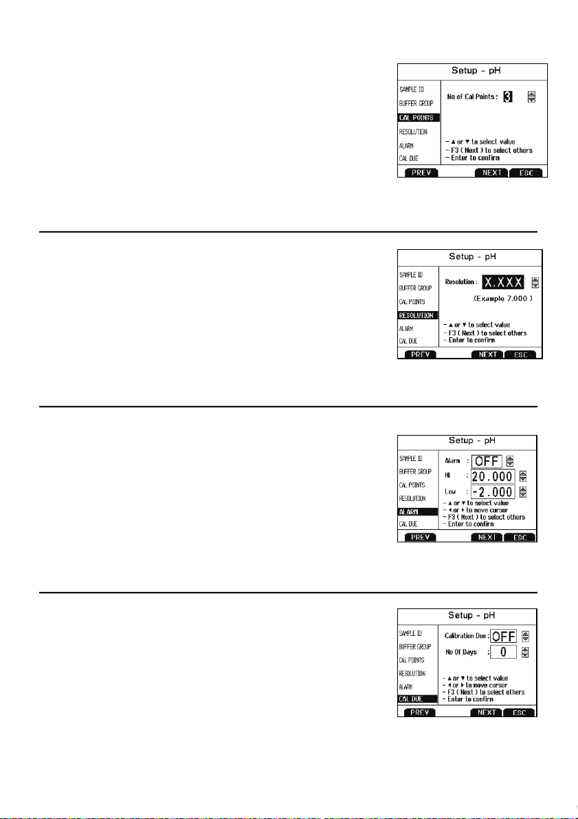
Cal Points
Specify the number of pH calibration points you intend to
calibrate with. Select the number of calibration points
from 1 to 5 with preset buffer groups or from 2 to 5
points with custom buffer group.
For example, if you have selected the USA buffer group
which contains 5 standards, but you will only be using 3
standards (pH 4, 7, and 10), selecting 3 calibration
points here will speed up the calibration process—the 2700 will automatically
recognize calibration is finished after the 3
rd
point has been completed.
Resolution
Select your desired pH resolution;
0.0, 0.00, or 0.000. Tip: Don’t choose more than you
really need—0.00 is the factory default setting since it is
most commonly used. Choosing 0.000 will lead to more
“unstable” conditions and cause a delay in obtaining the
final reading as the last digit (which is often not needed)
changes.
Alarm
The 2700 offers a visual and audible alarm to alert you
when the High or Low values that have been set from
this menu are exceeded.
“High Alarm” or “Low Alarm” will blink on the display if
the values are exceeded while simultaneously, a loud,
intermittent beeping sound is heard. The alarms will continue until the conditions
are no longer met, and will only be active during measurement mode.
Cal Due
When enabled, the “Cal Due” indicator blinks if the
number of days since the last calibration has been
exceeded. Set the number of days from 1 to 31.
www.GlobalTestSupply.com
Page 15
12
5. pH Calibration (with preset buffer group)
For best results, periodic calibration with known accurate standards is
recommended prior to measurement. Calibrate with standards that bracket your
intended measuring range while including a neutral point (7.00, 6.86, or 6.79). For
example, if you expect to measure samples from pH 6.2 to 9.5, calibration with
4.01, 7.00, and 10.01 will work well.
The 2700 series meters can be calibrated with up to 5 preset or custom buffers
(up to 6 with DIN buffer group). The non-volatile memory retains all calibration
values upon meter shut down.
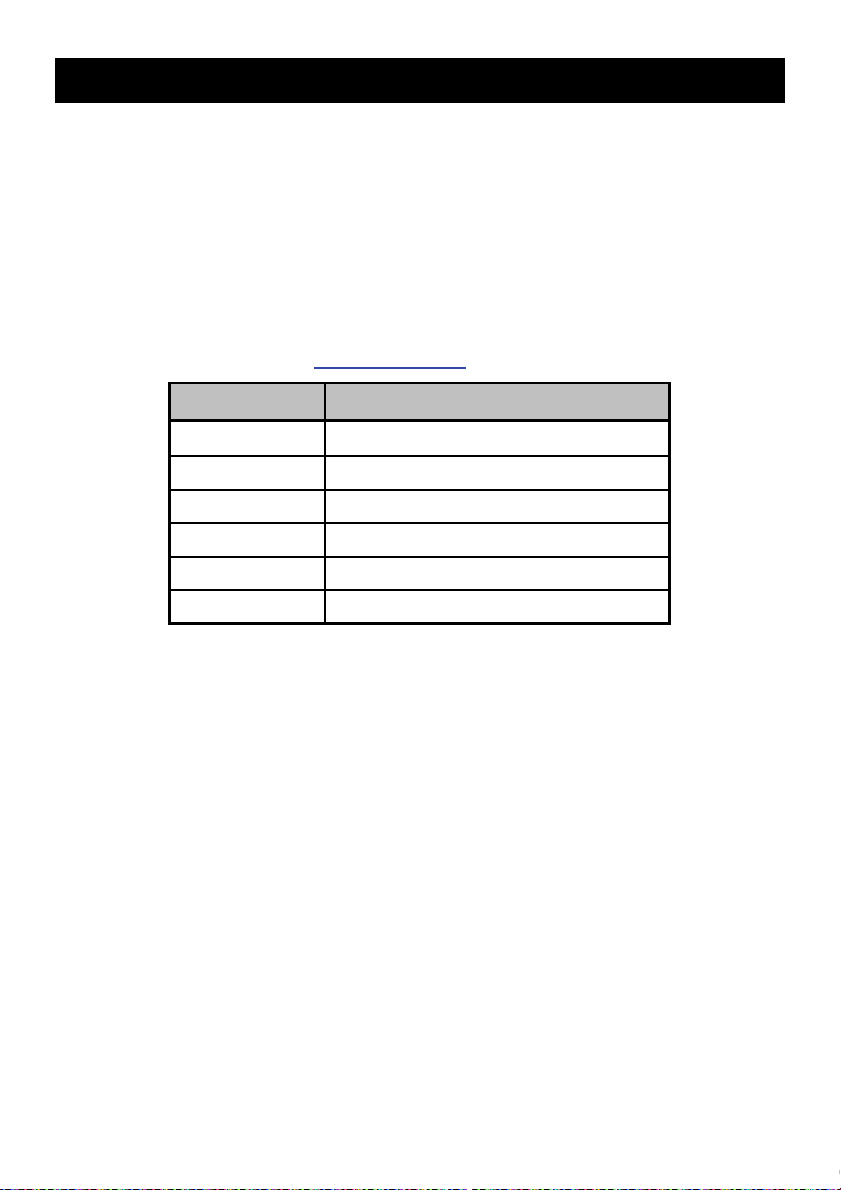
The 2700 series automatically recognizes the following pH calibration buffers in
the groups listed below. See
Buffer Group pH Values
Section4—Buffer to select a different buffer group;
USA
NIST
DIN
USER 1
USER 2
CUSTOM Any 2 - 5 values, ≥ 1.0 pH unit apart
*Required as 1st calibration point value (offset determination)
To eliminate temperature errors associated with the pH electrode, attach the
automatic temperature compensation (ATC) probe for best accuracy. Without
temperature compensation, pH accuracy will worsen as samples deviate from
25ºC and pH 7.
If the pH electrode has been stored dry, soak in storage solution for 10 minutes
before calibrating or taking readings to saturate the pH electrode surface and
minimize drift. If storage solution is not available, use a neutral pH buffer. Do not
reuse buffer solutions after calibration. Contaminants in the solution can affect the
calibration, and eventually the accuracy of the measurements.
1) Turn meter on, press MODE if needed for pH Measurement.
2) Rinse the pH and ATC electrodes with clean water then submerse in neutral
pH buffer—the 1st calibration point must be either 7.00, 6.86, or 6.79
depending on the buffer group used.
3) Press CAL to enter calibration mode.
1.68, 4.01, 7.00*, 10.01, 12.45
1.68, 4.01, 6.86*, 9.18, 12.45
1.09, 3.06, 4.65, 6.79*, 9.23, 12.75
1.68, 4.01, 7.00*, 9.18, 12.45
1.68, 4.01, 6.86*, 10.01, 12.45
www.GlobalTestSupply.com
Page 16
13
If the meter is password protected, you will be prompted to
enter a password. See Section 3—Password.
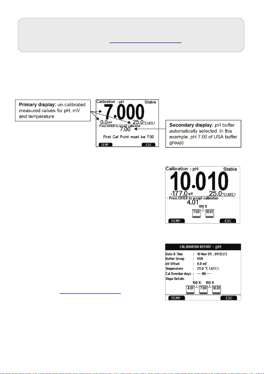
4) The primary display is the un-calibrated measured value. The 2700
automatically searches for and selects the appropriate value from your buffer
group in the secondary display. This value will blink when the ‘Stable’
indicator appears. Selecting CLR-C will clear the existing calibration.
5) Press ENTER to accept the calibration value
of the measured buffer. When successful the
accepted value will be visible inside of a
beaker icon. Percentage slope is visible after
two or more calibration points have been
completed.
6) Repeat Steps 4 & 5 with additional pH buffers
in any order or press ESC to escape and save
your calibration. When the specified number of
calibration points is met, the pH calibration
report page is automatically displayed.
To specify a different number of pH calibration
points see
Section 4—Cal Points.
www.GlobalTestSupply.com
Page 17
14
6. pH Calibration (with custom buffers)
For best results, enter the value of the buffer that corresponds
to the measured temperature. For example, pH 10 buffer is
actually 10.06 at 20°C, so adjust to 10.06 instead of 10.00 if
the temperature is 20°C.
Buffer Group pH Values
CUSTOM Any 2 - 5 values, ≥ 1.0 pH unit apart
1) Turn meter on, press MODE if needed for pH measurement mode.
2) Rinse the pH and ATC electrodes then submerse in your custom pH buffer—
any pH value can be used.
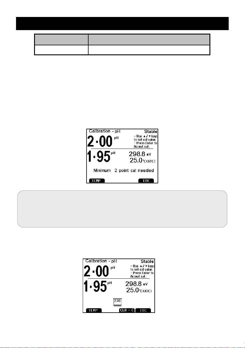
3) Press CAL (enter password if required) to enter calibration mode. If desired,
select CLR-C to clear the previous calibration. The lower pH value
corresponds to the factory default setting for reference. When stable, use the
up/down arrows to adjust the upper pH value to your custom pH buffer value.
4) Press ENTER to accept the calibration value. When successful, the accepted
value will be visible inside of a beaker icon.
www.GlobalTestSupply.com
Page 18
15
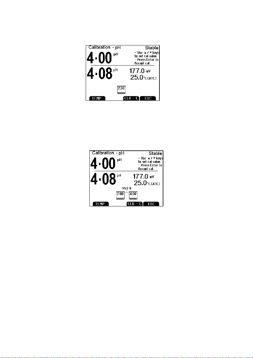
5) Rinse the pH and ATC electrodes then submerse in next custom pH buffer.
Use any pH value that is at least 1.0 pH unit from custom pH standards that
have already been calibrated.
6) Repeat Step 5 with additional pH buffers (up to 5 custom buffers) in any
order. Press ESC to escape and save your calibration at any time. When the
specified number of calibration points is met, the pH calibration report page is
automatically displayed. Percentage slope is visible after two or more
calibration points have been completed.
Additional pH calibration notes:
A single point (called “offset”) calibration is allowed with pH 7.00, 6.86, or 6.79
buffers but is not allowed with Custom buffer group. Although single point
calibration is allowed with preset buffer groups, we do not recommend this.
Instead, perform at least a 2-point calibration on a regular basis.
As soon as the first calibration value is accepted during a new calibration, all prior
calibration values are erased.
The pH calibration is a calibration of the complete meter / electrode(s) system
together, not the individual meter or electrode.
www.GlobalTestSupply.com
Page 19
16
7. Millivolt (mV) Calibration (Offset Adjustment)
Oxidization Reduction Potential (ORP or Redox) as measured by an ORP
electrode in mV units is not a precise measurement, but is useful as a relative
indicator. As such, mV offset adjustment is not meant to enhance accuracy, but
rather to make readings comparable to a reference.
Commercial ORP solutions are commonly used as a check standard—a
meter/electrode system is verified to be close to a given value although
adjustments are not made. These solutions can be used as a calibration standard
in which adjustments are made in an attempt to match the ORP value, however
results are often difficult to reproduce.
1) Turn meter on, connect an ORP electrode, and press MODE if needed for mV
(or R.mV) measurement.
2) Dip the ORP electrode into a solution with a known mV value (i.e. Zobel,
Light’s, quinhydrone, or iodidetriiodide) with brief or slow stirring.
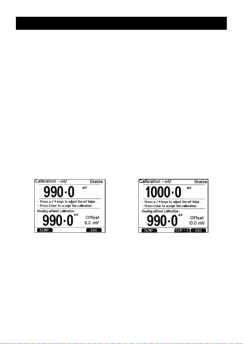
3) Press CAL when the reading is stable. The upper display shows the active
millivolt value (mV) while the lower display shows the factory default mV value
without calibration. The example below at right shows a mV calibration that
had previously been calibrated with a 10.0 mV offset.
4) Adjust the upper display using up/down arrows, press ENTER to accept the
calibration offset. The maximum adjustable value is ±150 mV from the factory
default mV value.
Additional mV calibration notes:
When an offset has been stored successfully, R.mV replaces mV in measurement
mode.
www.GlobalTestSupply.com
Page 20
17
8. Temperature Setup
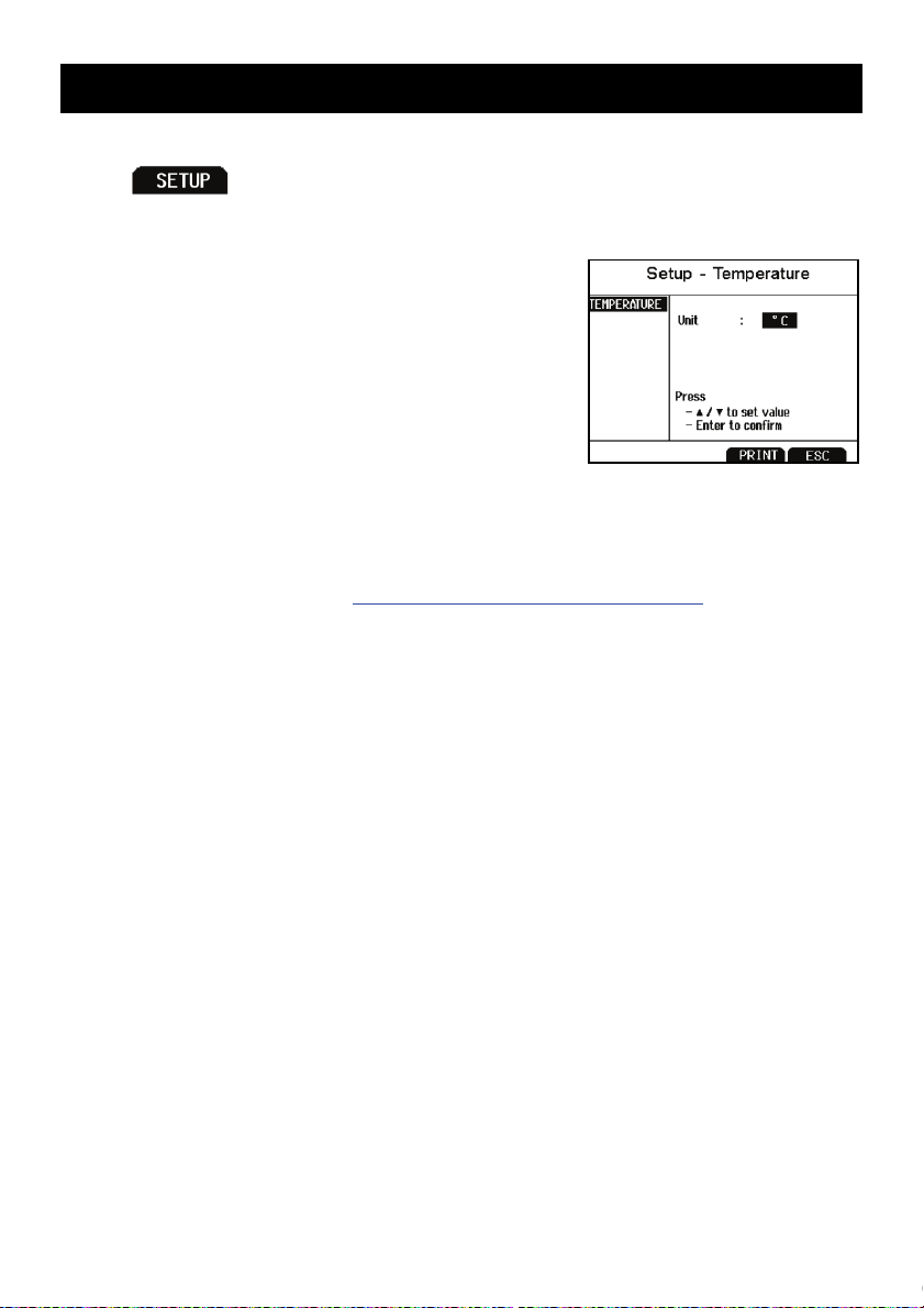
Use Setup Temperature mode to desired temperature units; º C or º F.
Press
TEMPERATURE is selected.
Choose º C or º F temperature units of measure.
Automatic Temperature Compensation (ATC) is automatically applied when a
temperature sensor is connected.
Manual Temperature Compensation (MTC) of 25 º C is used if the temperature
sensor is not connected. See
MTC temperature value.
from the measurement screen and then press ENTER when
Section 9—Temperature Calibration to adjust the
www.GlobalTestSupply.com
Page 21
18
9. Temperature Calibration
The thermistor sensor used for automatic temperature compensation and
measurement is both accurate and stable, so require frequent calibration isn’t
required. Temperature calibration is recommended upon electrode replacement,
whenever the temperature reading is suspect, or if matching against a certified
thermometer is desired.
1) Connect the temperature probe to the meter and place into a solution with a
known accurate temperature such as a constant temperature bath.
The temperature probe may be separate or built into a pH, Conductivity, or
Oxygen electrode. The PC 2700 has two temperature sensors available—one
built into Conductivity, and another for use with the BNC connection.
2) When the reading is stable, press CAL from any mode, then press
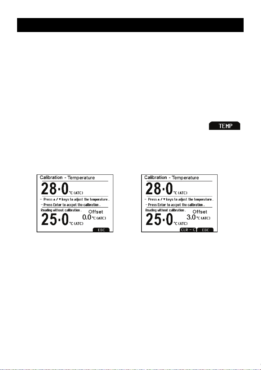
3) The upper display shows the active temperature while the lower display shows
the factory default temperature without calibration. The example below at right
shows a temperature calibration that had previously been calibrated with a 3.0
ºC offset.
.
3) Adjust the upper display using up/down arrows, press ENTER to accept the
calibration temperature. The maximum adjustable value is ±5 ºC (or ± 9 ºF)
from the factory default temperature value.
Additional temperature calibration notes:
For Manual Temperature Compensation (MTC) the procedure is the same
although the maximum adjustable value is the full temperature range of the
parameter, and connection of a separate ATC probe is not necessary.
For nearly all applications however, ATC is recommended.
If calibration is performed, be sure that the thermometry source used as a
reference is accurate!
www.GlobalTestSupply.com
Page 22
19
10. Conductivity, TDS, Salinity, & Resistivity Setup
Normalization Temperature
Use Setup mode to customize Conductivity, TDS, Salinity, & Resistivity
parameters.
Press
Conductivity, TDS, Salinity, or Resistivity is selected.
from the measurement screen and then press ENTER when
Sample ID
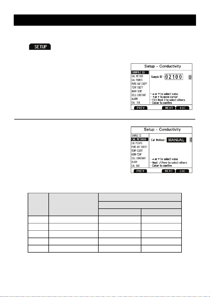
This is a user selectable number from 1 to 99999.
Incorporating a sample ID to identify one or more
data points is useful to distinguish data that is
saved into memory or sent to a PC or printer. Use
the up/down arrow keys to adjust the values and
left/right arrow keys to move the cursor.
Cal Method (conductivity mode only)
The 2700 is capable of automatic or manual
calibration for conductivity, and manual calibration
for TDS, Salinity, and Resistivity. This option
allows you to select AUTO (automatic) or
MANUAL conductivity calibration.
In the automatic calibration mode, the meter will
automatically select one of (4) conductivity
calibration standard values depending on the range and normalization
temperature being used (see table below).
Range
#
r 1 0.00 – 20.00 µS None None
r 2 20.1 – 200.0 µS 84 µS 76 µS
r 3 201 – 2000 µS 1413 µS 1278 µS
r 4 2.01 – 20.00 mS 12.88 mS 11.67 mS
r 5 20.1 – 200.0 mS 111.8 mS 102.1 mS
If you will only use one or more of the (4) calibration standards listed here,
Conductivity
Range
Automatic Calibration Values
25 ºC 20 ºC
www.GlobalTestSupply.com
Page 23
20
automatic calibration is recommended. Otherwise, manual calibration should be
selected.
The factory default is automatic conductivity calibration. Note that automatic
calibration is not available for conductivity range 1.
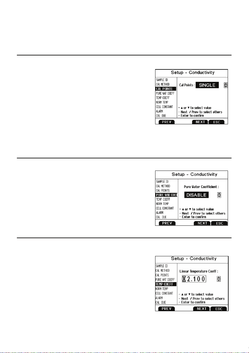
Cal Points
Use SINGLE for Single-Point Calibration (SPC) to
apply a single calibration value across all ranges.
Use MULTI for Multi-Point Calibration (MPC) to
calibrate each range individually. This will restrict
an individual calibration so that it is applied to one
range only. When using multi-point calibration,
perform a calibration in each range that you
expect to use for best results.
The factory default is SPC. SPC or MPC will be shown with the calibration details
in measurement mode.
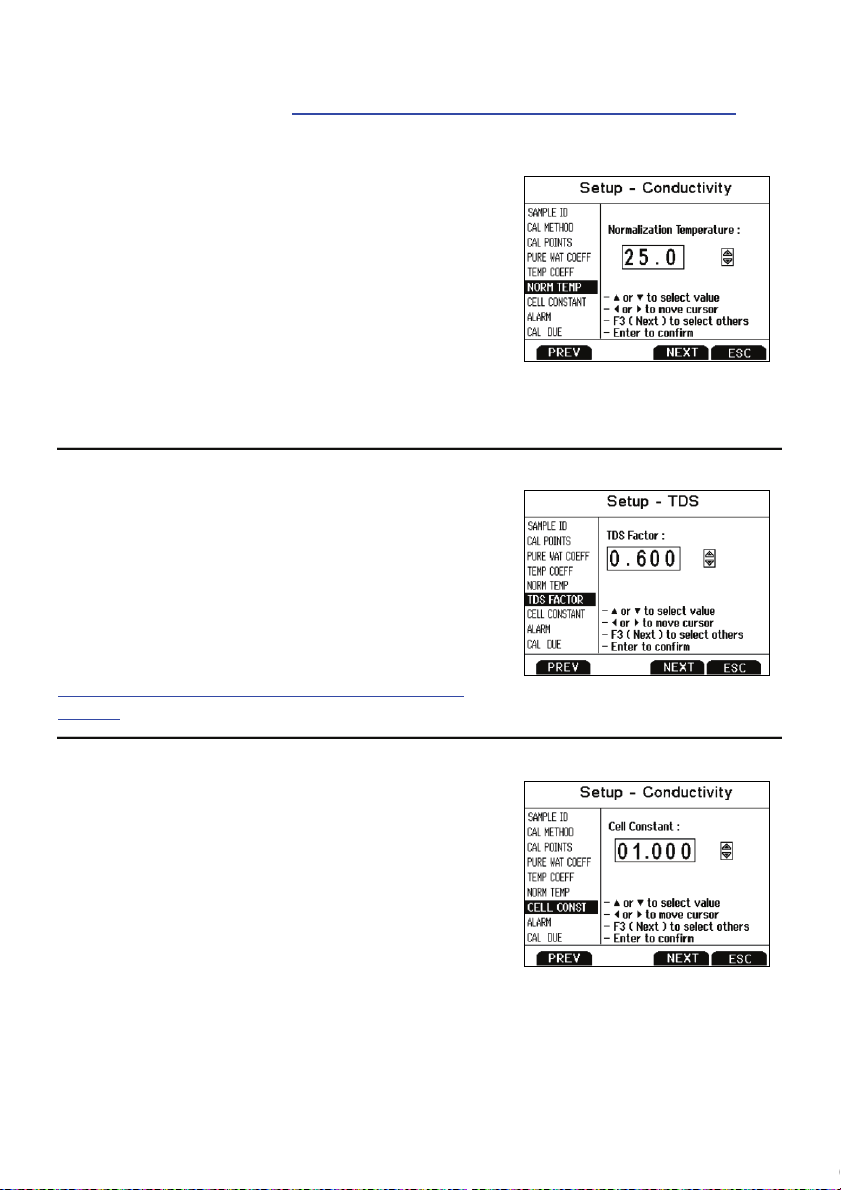
Pure Water Coefficient
Choose ENABLE to automatically apply pure
water temperature correction for measurements
below 2
µS (ultra pure water).
Note: this option does not apply to Salinity mode.
Temperature Coefficient (linear)
The temperature coefficient is the amount of
change in conductivity per degree temperature (%
per ºC). The factory default setting is a
temperature coefficient of 2.1 % per ºC. For most
applications this will provide good results. The
meter allows adjustment from 0.0 to 10.0.
TIP: Select 0.0% for uncompensated
measurements. The temperature will be measured
by the electrode and displayed in measurement mode—without compensation.
www.GlobalTestSupply.com
Page 24
21
Note: this option does not apply to Salinity mode.
For more information, see
Section 20—Calculating Temperature Coefficients.
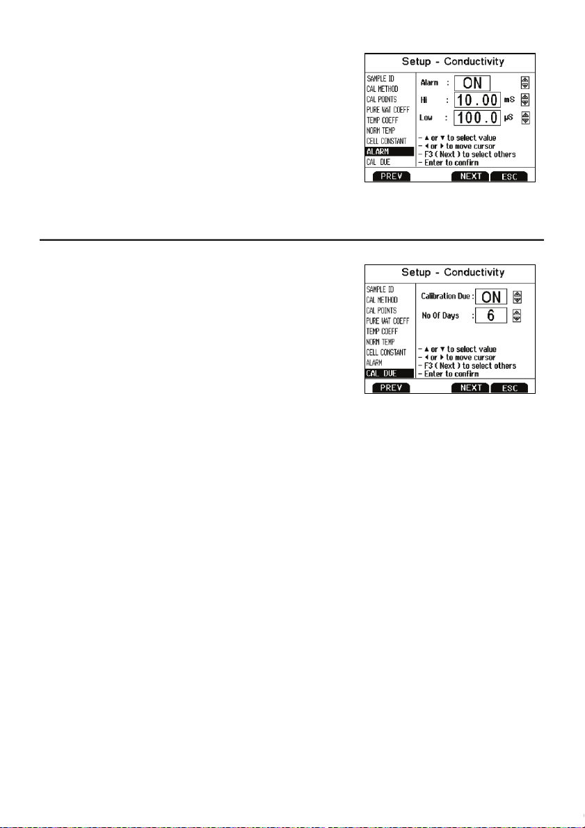
Normalization Temperature (°C)
When Automatic Temperature Compensation is
used, measurements are adjusted by the
temperature coefficient to the normalization
temperature.
Adjust the value from 15.0 to 35.0 º C.
Note: Use the normalization temperature that is
referenced on your calibration standard(s). This will usually match the 2700
factory default value (25 º C).
TDS Factor
The TDS conversion factor is the number used by
the 2700 to convert from conductivity to TDS. The
TDS conversion factor automatically adjusts the
reading. Select the desired TDS factor from 0.400
to 1.000.
See Section 21—Calculating TDS Conversion
Factor for information on Calculating TDS factor
(TDS mode only)
Cell Constant
The 2700 includes a probe with a nominal cell
constant (k) of 1.0. Use probes with k = 0.1 and 10
(sold separately) for improved performance in
extreme sample ranges. The factory default is 1.0
to match the included probe. Cell constant can be
adjusted from 0.010 to 10.000.
k = 0.1 ideal for low measurements <20 µS (<10 ppm).
k = 1.0 ideal for mid-range measurements
k = 10 ideal for high measurements >20 mS (>10 ppt).
www.GlobalTestSupply.com
Page 25
22
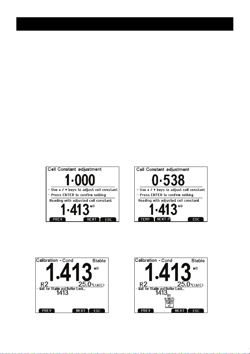
Alarm
The 2700 offers a visual and audible alarm to alert
you when the High or Low values that have been
set from this menu are exceeded.
“High Alarm” or “Low Alarm” will blink on the
display if the values are exceeded while
simultaneously, a loud, intermittent beeping sound
is heard. The alarms will continue until the
conditions are no longer met, and will only be active during measurement mode.
Cal Due
When enabled, the “Cal Due” indicator blinks if the
number of days since the last calibration has been
exceeded. Set the number of days from 1 to 31.
www.GlobalTestSupply.com
Page 26
23
11. Conductivity Calibration (automatic)
For best results, periodic calibration with known accurate standards is
recommended prior to measurement. Calibrate with standards that are close in
value to your intended sample(s).
When using multi-point calibration, perform a calibration in each range that you
expect to use for best results.
If the conductivity electrode has been stored dry for some time, soaking in alcohol
or clean water for a few minutes can help performance.
1) Turn meter on, press MODE if needed for conductivity measurement mode.
2) Press CAL if needed to enter calibration mode. Rinse the electrode with
clean water then submerse
µS, 12.88 mS, or 111.8 mS. Provide stirring for best results.
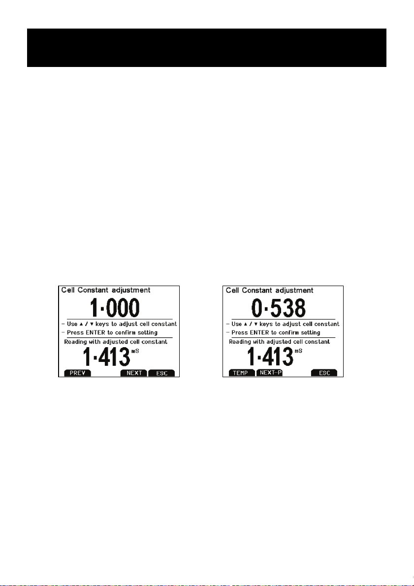
3) Use the up/down arrows to adjust the cell constant manually or press NEXT
to keep the nominal cell constant value and proceed with a typical automatic
calibration (recommended). If adjusting the cell constant manually, press
ENTER after ‘Stable’ appears to confirm the adjustment.
Before and after a manual calibration constant adjustment
into your conductivity standard— either 84 µS, 1413
4) Wait for the meter to lock on the calibration standard and press ENTER after
‘Stable’ appears to confirm the calibration point. The calibrated value, Range
(R) that was calibrated and the calculated cell constant are now shown.
Before and after a one-point automatic conductivity calibration with 1.413 mS
www.GlobalTestSupply.com
Page 27

24
5) For multi-point calibration repeat steps 2 & 3 with additional standards. Press
“2 Cell’ or “4 Cell’ electrode is automatically detected and
displayed on the measurement screen when connected.
ESC to save the calibration, or press NEXT to view the calibration report.
Calibrate one point per range, up to 4.
Additional automatic conductivity calibration notes:
A maximum of one calibration point per range can be performed. If multiple
calibration points are used in the same range, the most recent one will replace
the previous one.
When the electrode is replaced, it is best to clear the calibration to the factory
default values.
Rinse or immerse the probe before calibration and between samples with clean
water (deionized water is ideal).
To protect from erroneous calibrations, the allowable tolerance is ±40% of the
factory default value.
For best results always begin with your lowest calibration standard value,
followed by the next lowest, and so on.
Low conductivity standard solutions (less than 20 µS) are unstable and are very
temperature dependent. As a result, reproducible calibration results are
challenging in lowest measurement range #1 (0.00 to 20.0 µS).
www.GlobalTestSupply.com
Page 28
25
12. Conductivity, TDS, Salinity, & Resistivity
Calibration (manual adjustment)
For best results, periodic calibration with known accurate standards is
recommended prior to measurement. Calibrate with standards that are close in
value to your intended sample(s).
When using multi-point calibration, perform a calibration in each range that you
expect to use for best results.
If the electrode has been stored dry for some time, soaking in alcohol or clean
water for a few minutes can help performance.
1) Turn meter on, press MODE if needed for the appropriate mode.
2) Press CAL if needed to enter calibration mode. Rinse the electrode with
clean water then submerse into your calibration standard.
3) Use the up/down arrows to adjust the cell constant manually or press NEXT
to keep the nominal cell constant value and proceed with a typical manual
calibration (recommended). If adjusting the cell constant manually, press
ENTER after ‘Stable’ appears to confirm the adjustment.
Before and after a manual calibration constant adjustment
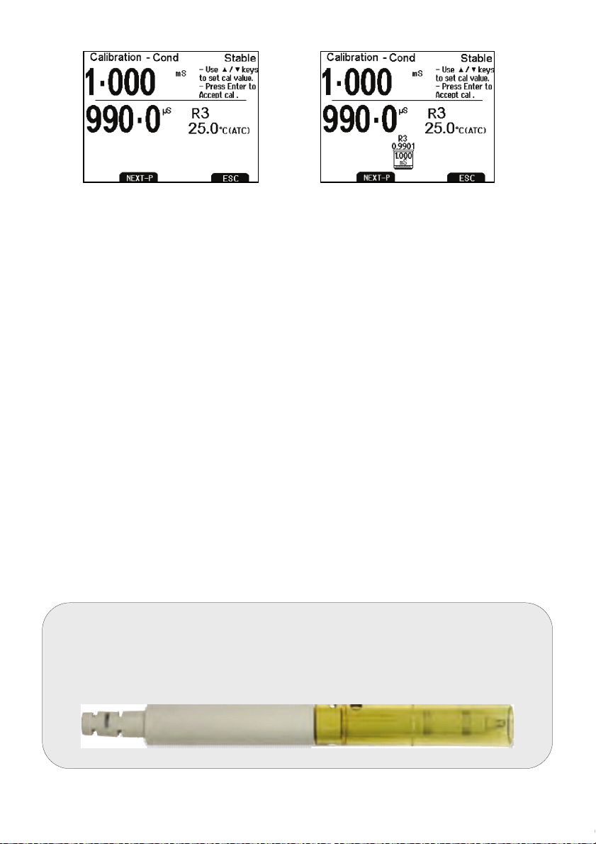
4) The upper display is the active reading while the lower display is the factory
default value without calibration. Use the up/down arrows to adjust the upper
display to match the desired calibration value. Press ENTER after ‘Stable’
appears to confirm the calibration. The calibrated value, Range (R) that was
calibrated and the calculated cell constant are now shown.
www.GlobalTestSupply.com
Page 29
26
Note: If using the 2-cell electrode, the protective probe guard
attached during measurement and calibration. Erroneous
results will occur while the probe guard is removed.
Before and after a manual calibration
5) For multi-point calibration repeat with additional standards. Press ESC to
save calibration or press NEXT to view the calibration report. Calibrate one
point per range, up to 5 points.
Additional manual calibration notes:
A maximum of one calibration point per range can be performed. If multiple
calibration points are used in the same range, the most recent one will replace
the previous one.
When the electrode is replaced, it is best to clear the calibration to the factory
default values.
Rinse or immerse the probe before calibration and between samples with clean
water (deionized water is ideal).
To protect from erroneous calibrations, the allowable tolerance is ±40% of the
factory default value.
For best results always begin with your lowest calibration standard value,
followed by the next lowest, and so on.
Low conductivity standard solutions (less than 20 µS) are unstable and are very
temperature dependent. As a result, reproducible calibration results are
challenging in lowest measurement range #1 (0.00 to 20.0 µS).
can be removed temporarily for cleaning however it must be
re-
www.GlobalTestSupply.com
Page 30
27
13. Ion Setup
Use Setup Ion mode to customize this parameter. Press from the
measurement screen and then press ENTER when ION is selected.
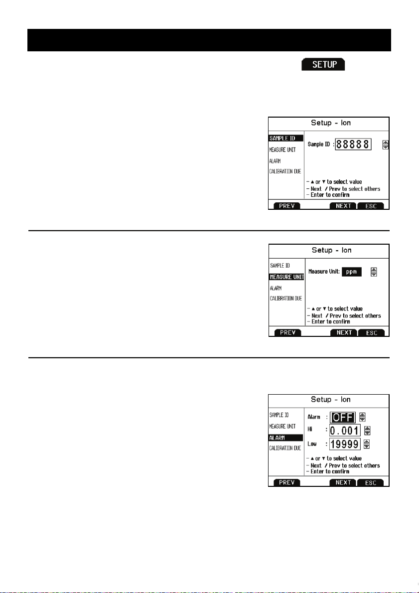
Sample ID
This is a user selectable number from 1 to 99999.
Incorporating a sample ID to identify one or more
data points is useful to distinguish data that is saved
into memory or sent to a PC or printer. Use the
up/down arrow keys to adjust the values and
left/right arrow keys to move the cursor.
Measure Unit
Select ppm, molar, or mg/L ion concentration units.
Alarm
The 2700 offers a visual and audible alarm to alert
you when the High or Low values that have been
set from this menu are exceeded.
“High Alarm” or “Low Alarm” will blink on the display
if the values are exceeded while simultaneously, a
loud, intermittent beeping sound is heard. The
alarms will continue until the conditions are no
longer met, and will only be active during
measurement mode.
www.GlobalTestSupply.com
Page 31
28
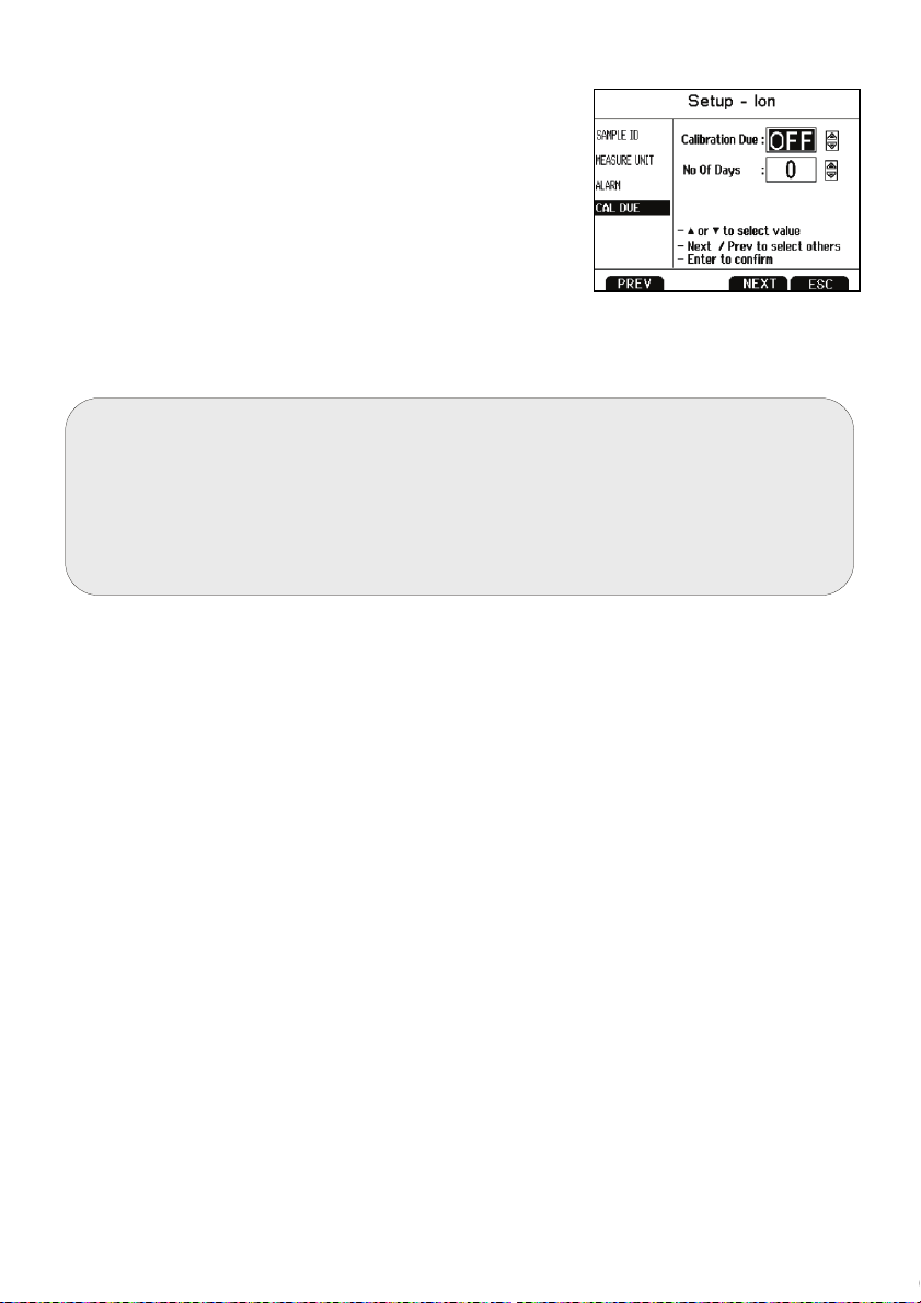
Cal Due
Refer to your Ion Selective Electrode instruction manual for
details on conditioning, storage, maintenance, calibration
standard preparation, Ionic Strength Adjustment,
and operation that is specific to the electrode and ion of
interest.
When enabled, the “Cal Due” indicator blinks if the
number of days since the last calibration has been
exceeded. Set the number of days from 1 to 31.
troubleshooting, etc. Each ISE is unique and requires care
www.GlobalTestSupply.com
Page 32
29
14. Ion Calibration
The primary display will show “- - - -” when ion
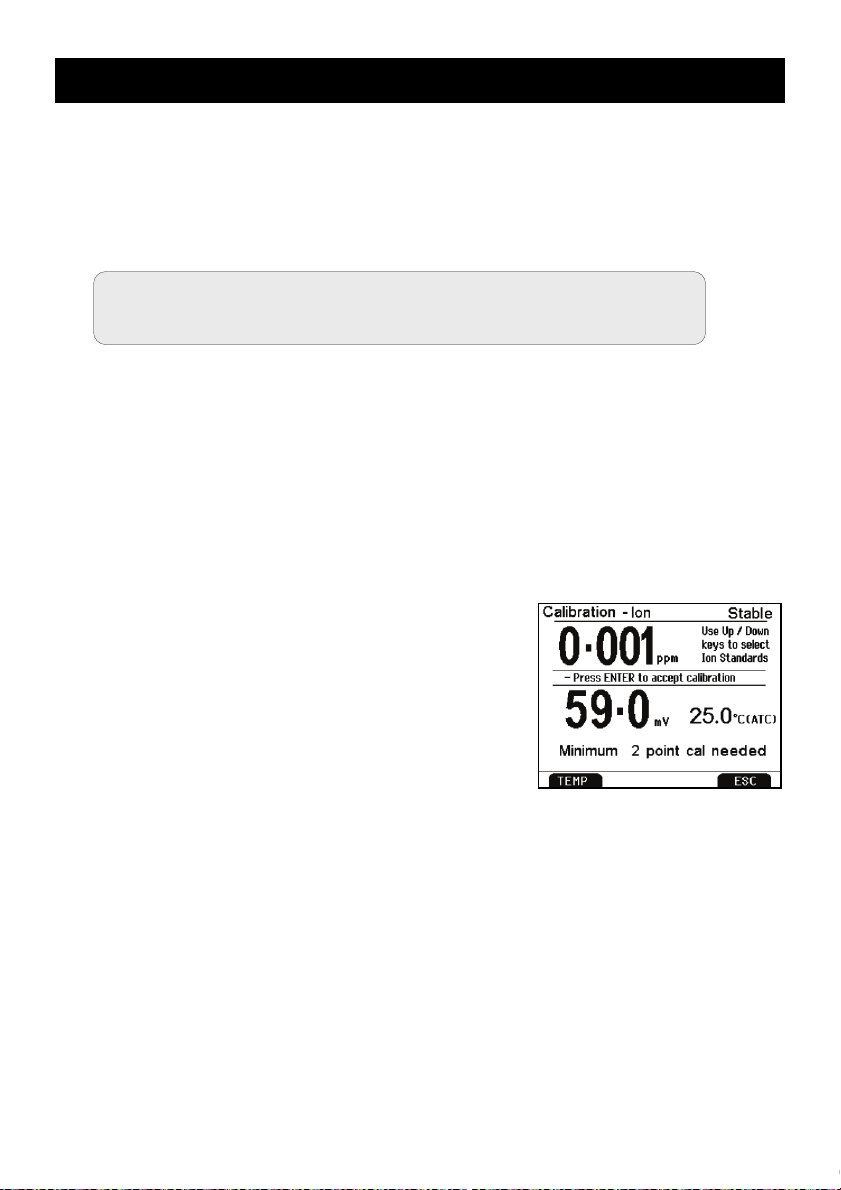
The ION 2700 can measure ion concentration such as ammonia or fluoride when
using an ion selective electrode (ISE) for the specific ion of interest.
Ion calibration is required with at least two standards from (8) available values;
0.001, 0.01, 0.1, 1.0, 10, 100, 1000, and 10000.
calibration is required for ion measurement.
Prepare ion calibration standards that bracket your measurement range. Follow
the ion selective electrode instruction manual for the appropriate ionic strength
adjustment and sample preparation.
For best results always begin with your lowest calibration standard value,
followed by the next lowest, and so on.
1) Connect the ISE and press MODE as needed for concentration mode.
2) Rinse the ISE with clean water then dIp into
your lowest calibration standard and stir.
Press CAL. Use up/down arrows to match
the upper display to your calibration
standard.
3) The lower display is the mV reading of the ISE. Press ENTER when this
value is stable to accept the calibration point.
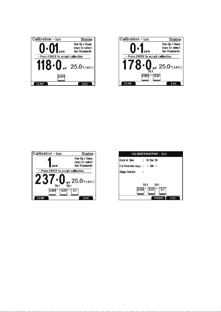
4) Rinse the ISE with clean water and dp into your next lowest calibration
standard and stire. PressENTER after “Stable” appears to accept the
next calibration point.
www.GlobalTestSupply.com
Page 33
30
Before and after a two point ion calibration using 0.001 and 0.01 standards
5) The mV/decade slope value will be displayed if the calibration is successful.
“Slope Error” indicates that the calibration for the current point was not
successful. This occurs when the slope (mV difference between two
consecutive points) is < 15 mV/decade or > than 90 mV/decade.
6) Repeat steps 4 & 5 with additional ISE standards or press ESC to escape
and save your calibration.
At left; a three point ion calibration, at right; the Ion calibration report
To view the Ion Calibration Report at any time from the measure screen, press
REPORT.
www.GlobalTestSupply.com
Page 34
31
15. Dissolved Oxygen Setup
Use Setup Dissolved Oxygen mode to customize the parameter. Press
from the measurement screen and then press ENTER when DO% or DO (mg/L)
is selected for percent saturation or concentration modes respectively. Note that
setup parameters differ slightly depending on which is selected.
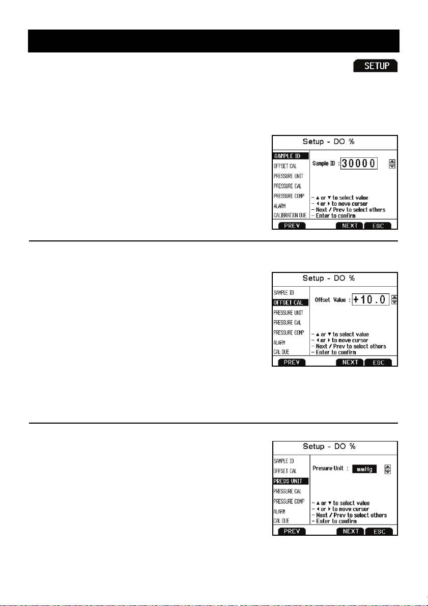
Sample ID
This is a user selectable number from 1 to 99999.
Incorporating a sample ID to identify one or more
data points is useful to distinguish data that is
saved into memory or sent to a PC or printer. Use
the up/down arrow keys to adjust the values and
left/right arrow keys to move the cursor.
Offset Cal (% saturation only)
Use this feature to offset the meter’s value to
another DO meter. Using the % saturation mode,
observe the reading a sample solution after it has
stabilized. Similarly, observe the reading of the
same sample using another DO meter as a
reference. The probe of the reference meter should
be immersed in the same sample at the same
depth.
The DO 2700 allows ±10% offset adjustment. Note that subsequent user
calibrations will reset the offset adjustment back to the factory default value of 0.0
% offset.
Pressure Unit (% saturation mode only)
Select mmHg or kPa pressure units.
www.GlobalTestSupply.com
Page 35
32
Pressure Cal (% saturation mode only)
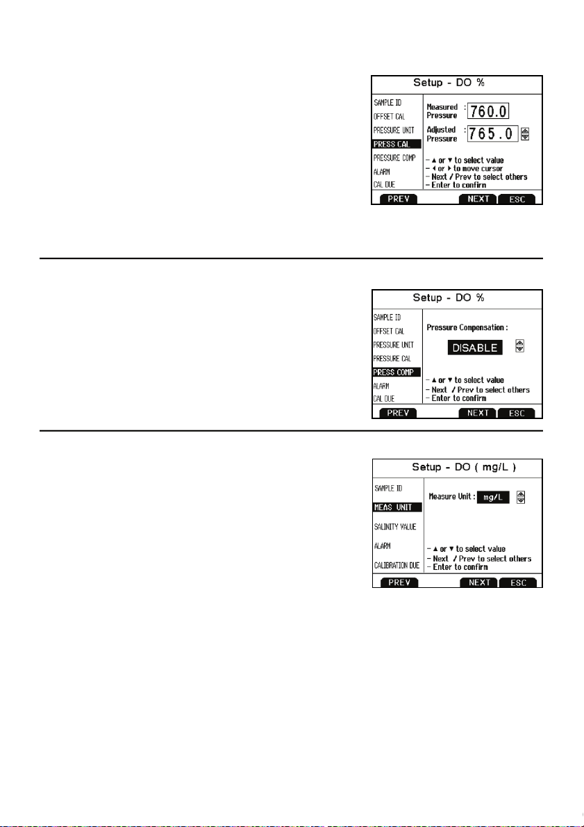
The DO 2700 includes a built-in barometer that is
factory calibrated. While frequent pressure
adjustment is not required, adjustments can be
made in the Adjusted Pressure field. The
Measured Pressure is the active pressure value
measured by the DO 2700.
Note: if adjusting, “true” barometric pressure—that
has not been corrected to sea level, must be used.
Pressure reported by weather services are almost always corrected and therefore
are not appropriate for entry in the adjusted pressure field here.
Pressure Compensation (% saturation mode only)
Select ENABLE or DISABLE.
Measure Unit (concentration mode only)
Select mg/L or ppm concentration units.
www.GlobalTestSupply.com
Page 36
33
Salinity Value (concentration mode only)
Enter the salinity value of your samples in parts per
thousand (ppt) units. Select from 0 to 50.0 ppt.
Alarm
The 2700 offers a visual and audible alarm to alert
you when the High or Low values that have been
set from this menu are exceeded.
“High Alarm” or “Low Alarm” will blink on the display
if the values are exceeded while simultaneously, a
loud, intermittent beeping sound is heard. The
alarms will continue until the conditions are no
longer met, and will only be active during measurement mode.
Cal Due
When enabled, the “Cal Due” indicator blinks if the
number of days since the last calibration has been
exceeded. Set the number of days from 1 to 31.
www.GlobalTestSupply.com
Page 37
34
16. Dissolved Oxygen Calibration
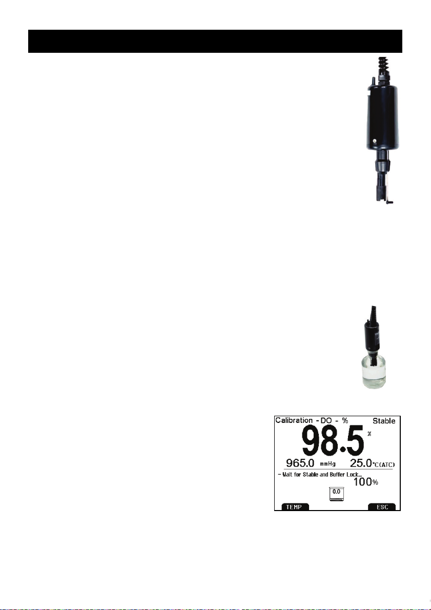
The DO 2700 utilizes a self-stirring polargraphic electrode with a built-in
temperature sensor. The electrode is designed for use in BOD bottles.
Power the meter on 5-15 minutes before calibration or taking a
measurement as this will allow adequate time for the electrode to warm
up. Longer warm up times are recommended when the membrane cap
and/or electrolyte in replaced—this permits the probe to use up all
oxygen retained inside the cap.
The DO 2700 has two modes; % saturation and concentration (mg/L or
ppm). In % saturation mode, the DO 2700 will accept either a one
(100%) or two point (100% & 0%) calibration. For a one point
calibration, 100% air calibration is recommended. For best accuracy
below 2.0 ppm, use zero oxygen solution to calibrate 0%. 0% calibration followed
by 100% calibration is not recommended—always perform 100% calibration first.
Always rinse the probe with clean water before and after each calibration/sample
measurement. When performing air calibration, gently shake remaining water
droplets from the probe’s membrane.
100 % Calibration
1) Power meter on with DO electrode attached for 5-15 minute warm
up.
2) Rinse the probe well with clean water then place into a BOD bottle
partially filled with water (100 mL or so).
3) Press MODE if needed for % measurement mode.
4) Press CAL. The primary reading is the current
measured value. Note: the stirrer is not
required for air calibration. For air-saturated
water calibration however, switch the stirrer
motor on (the switch is located at the top of the
electrode) during calibration and measurement.
5) Allow the reading to stabilize and lock on
100%. Press ENTER to confirm the calibration.
6) Press ESC to return to measurement mode, or continue with 0% calibration in
step 7 if desired.
www.GlobalTestSupply.com
Page 38
35
0% Calibration
7) After completing steps 1 thru 6 for 100% saturation calibration, place your
electrode in zero oxygen solution (0.08M sodium sulfite). Continuous stirring
is not required.
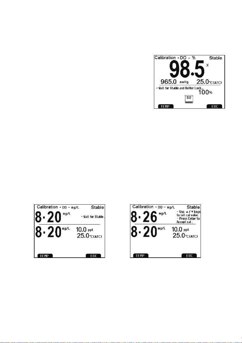
8) The primary reading is the current measured
value. Be patient—the reading can take
several minutes to reach 0% saturation!
9) When the reading has finally stabilized and
locked on 0% press ENTER to confirm the
calibration.
mg/L or ppm (Concentration) Calibration
1) Connect the DO electrode and power on DO 2700 for 5-15 minute warm up.
2) Press MODE if needed for concentration measurement mode.
3) Rinse the probe well with clean water then place into your solution with a
known dissolved oxygen concentration value (i.e. determined by titration or
another instrument).
4) Press CAL and switch the stirrer on. The upper reading is the current
measured value. The lower reading is the factory default reading for
comparison, along with salinity and temperature correction shown.
A manual DO concentration calibration
5) Allow the reading to stabilize. Use the up/down arrows to adjust the upper
reading to match the DO concentration of your solution.
The minimum
concentration calibration value is 2.00 mg/L. Press ENTER to confirm the
calibration.
www.GlobalTestSupply.com
Page 39
36
Additional dissolved oxygen calibration notes:
% Saturation
(of factory default value)
• Keep the membrane free from contact with solid objects.
• Use with aqueous solutions only.
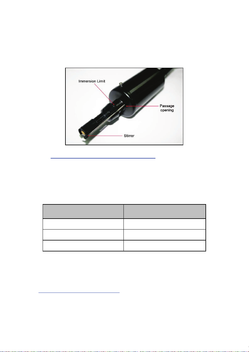
• Do not submerse the probe past the immersion limit (see below).
• See Section 22—DO Electrode Maintenance
• Calibration adjustment is limited to ±40% of the factory default value to
prevent erroneous calibrations.
• If % calibration is attempted with a value of 10.1% to 49.9%, a
“Calibration Error” will result. The following table lists corresponding
calibration values in % saturation calibration mode:
less than 10% 0%
10.1% to 49.9% Calibration Error
50% to 150% 100%
• Calibration of the concentration mode will only replace the previous
concentration calibration and does not affect the % saturation calibration.
• To offset your % saturation reading to match another instrument, see
Section 15—Offset Calibration.
• Perform daily calibration for best results. New calibration values will
automatically override the previous calibration.
for additional information.
Calibration Value
www.GlobalTestSupply.com
Page 40
37
17. Transferring and Printing Data
To send data directly to a printer or PC, connect the 30X427301 / 35420-01 cable
to the RS-232 output port of the 2700. To connect to a USB port, an additional
adapter cable is required; see
The 2700 can be used to:
• Print/send one or more data points directly to a dedicated printer or to
a PC. Press PRINT from measurement mode or from the MEM OUT
screen.
• Print/send the calibration report to a printer or PC. Press REPORT
from measurement mode.
• Send live data to a PC at intervals 3 seconds or higher. In the
System Setup, select a “TIMED” Print Set.
Choose the “TEXT/PRINTER” Print Format option to transfer the data in an easily
viewable format—best for printing.
Choose the “CYBERCOMM” Print Format option to send the data as a comma
separated value (CSV)—best for exporting data into software
Section 25—Replacements & Accessories.
To make changes to the printer, datalog, and output settings, see
System Setup.
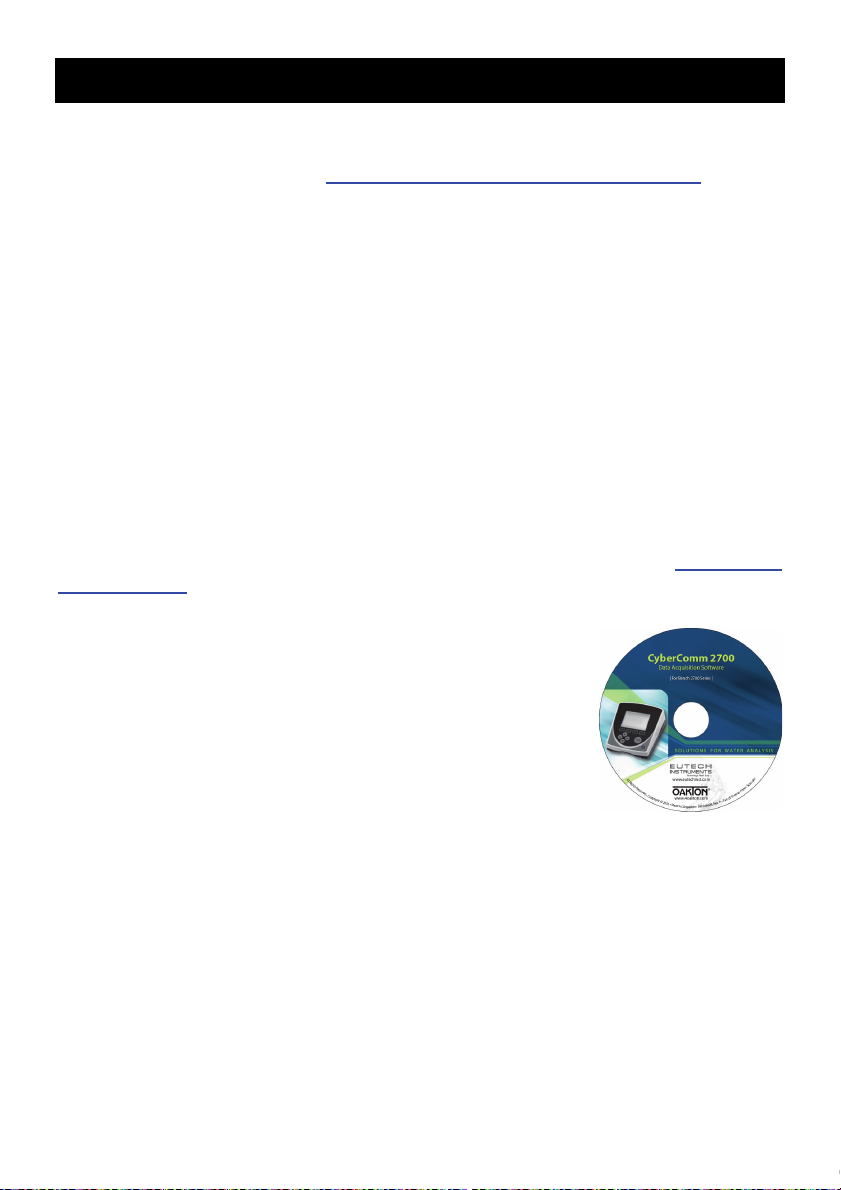
Certain 2700 models will include a complimentary software
application called CyberComm 2700. For details on
installation, connection and usage of this software, please
read the manual that is included on the software CD. If you
did not receive a CD or lost the CD that was included with
your instrument, check our website.
rd
The 2700 is also compatible with 3
software.
party capture
Section 3—
www.GlobalTestSupply.com
 Loading...