

Operating Manual
EcoTestr™ EC1 Pocket Tester
Keypad Functions
Short press = <2 seconds
Long press = >2 seconds
1. Short press to turn on; long press to
turn off.
MEAS
CAL
<
2. When turned off, long press to enter
setup mode.
3. In mode setting, short press to change
parameter.
1. When turned on, long press to enter
calibration mode.
2. In calibration mode, short press to
confirm calibration.
3. In mode setting, short press to confirm
parameter selection.
Calibration
1. Rinse the probe in distilled water and gently dry with a
clean tissue. Short press
2. Long press CAL/ to enter calibration mode;
short press
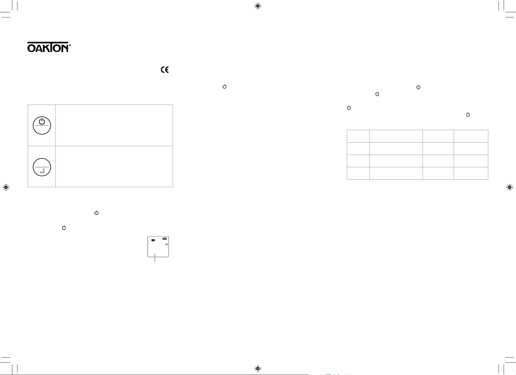
3. Dip the probe into 1413 µS/cm calibration
solution. Stir gently, leave it to stand. Wait
for the measurement stability icon (
appear and stay on the display (see Fig 1);
then short press CAL/ to complete the 1st
calibration. Tester returns to measurement
mode, and calibration icon “M” appears
on bottom left side of display.
4. Rinse probe in distilled water and dry it. Repeat steps
#2 and #3 to complete 2nd calibration in 12.88 mS/cm
calibration solution. Tester returns to measurement
mode, and calibration icons “M” and “H” will appear
on bottom left side of display.
/MEAS to exit.
/MEAS to turn on the tester.
Cond
) to
1433
1413
Figure 1
Measurement
1. Short press /MEAS to turn on the tester. Rinse probe
in distilled water and dry it gently with a clean tissue to
remove excess water.
2. Stir the probe in the sample solution gently, leave it to
stand. Wait for the stability icon (
take a reading.
3. Rinse off the tester thoroughly in distilled water after
each test.
Notes:
• If this is the rst-time use or the tester hasn’t been used
for a long time, we recommend soaking the probe in
12.88 mS/cm solution for 15 to 30 minutes to restore its
sensitivity and speed up the response time.
• The tester adopts 1413 µS/cm and 12.88 mS/cm standard
calibration solutions. User can use 1 and 2 point calibrations as needed. For most circumstances, calibrating in
1413 µS/cm to complete the 1st point calibration will
meet testing requirements.
• The tester has already been calibrated after manufac-
ture. User can use the tester immediately or can test it in
µ
S
the calibration solutions to test its accuracy. If error is
large, calibrate the tester before using.
• We recommend replacing the calibration solution after
5 to 10 calibrations to maintain accuracy.
) to remain on, then
Setting the Parameters
When tester is off, long press /MEAS to enter setup mode.
Short press
press CAL/ and parameter will flash, then short press
/MEAS to choose desired parameter. Short press
CAL/ to confirm parameter selection. Long press
to return to measurement mode.
Symbol Menu setting Selection
P1
P2
P3
*Aut = all ranges (0 to 199.9 µS/cm, 20 to 1999 µS/cm, 2.0 to 20.0 mS/cm)
Notes:
• Once the readings are greater than 2000 µS/cm, the unit
will automatically become mS/cm.
• Select “Yes” for P3 to restore the calibration to the
theoretical values and parameter setting to original
values. When tester’s calibration or measurement
performs abnormally, this function can be adopted so
the tester returns to factory default setting and then
users can conduct calibration or take measurements
again.
/MEAS to switch from P1 to P2 to P3. Short
Factory
default
Select conductivity
range*
Select temperature
unit
Restore to
factory default
Aut* – µS –
mS
°F – °C °C
No – Yes No
/MEAS
Aut
1065O101_MAN_EC1_35634-06.indd 1 03/22/2018 3:49:52 PM
Self-Diagnostic Messages
Symbol
Er 1
Er 2
Self-diagnosis
information
Wrong calibration
solution, or measured
value is not within the
range of the tester.
CAL/ is pressed
before measurement
is stable ( appears).
How to fix
• Check if calibration
solution is correct.
• Check if probe is
damaged.
Wait for the
measurement
stability icon () to
appear and stay, then
press CAL/ .
Specifications
Range
Resolution 0.1/1 µS/cm, 0.01 mS/cm
Conductivity
Accuracy ±1% full-scale ± 1 digit
Calibration
points
Automatic
temperature
compensation
Range 32 to 122°F (0 to 50°C)
Temperature
Resolution 0.1°F/°C
Accuracy ±0.9°F (0.5°C)
Power: four AAA batteries (included); >400 hours of
continuous operation
Low-voltage warning:
battery status icon flashes
Auto power-off: tester automatically turns off after 8 minutes
of nonuse
IP rating: IP67 (waterproof), oats on water when sensor cap
is on
Dimensions (L x W x H): 7" x 1.5" x 1.25" (17.8 x 4 x 3.1 cm)
Weight: 3.8 oz (107 g)
0 to 200.0 µS/cm,
0 to 2000 µS/cm,
0 to 20.00 mS/cm
1 or 2 points; auto
standard recognition
32 to 122°F (0 to 50°C)
Ordering Information
Model Product description Catalog number
EC1
EcoTestr pocket
conductivity tester
35634-06
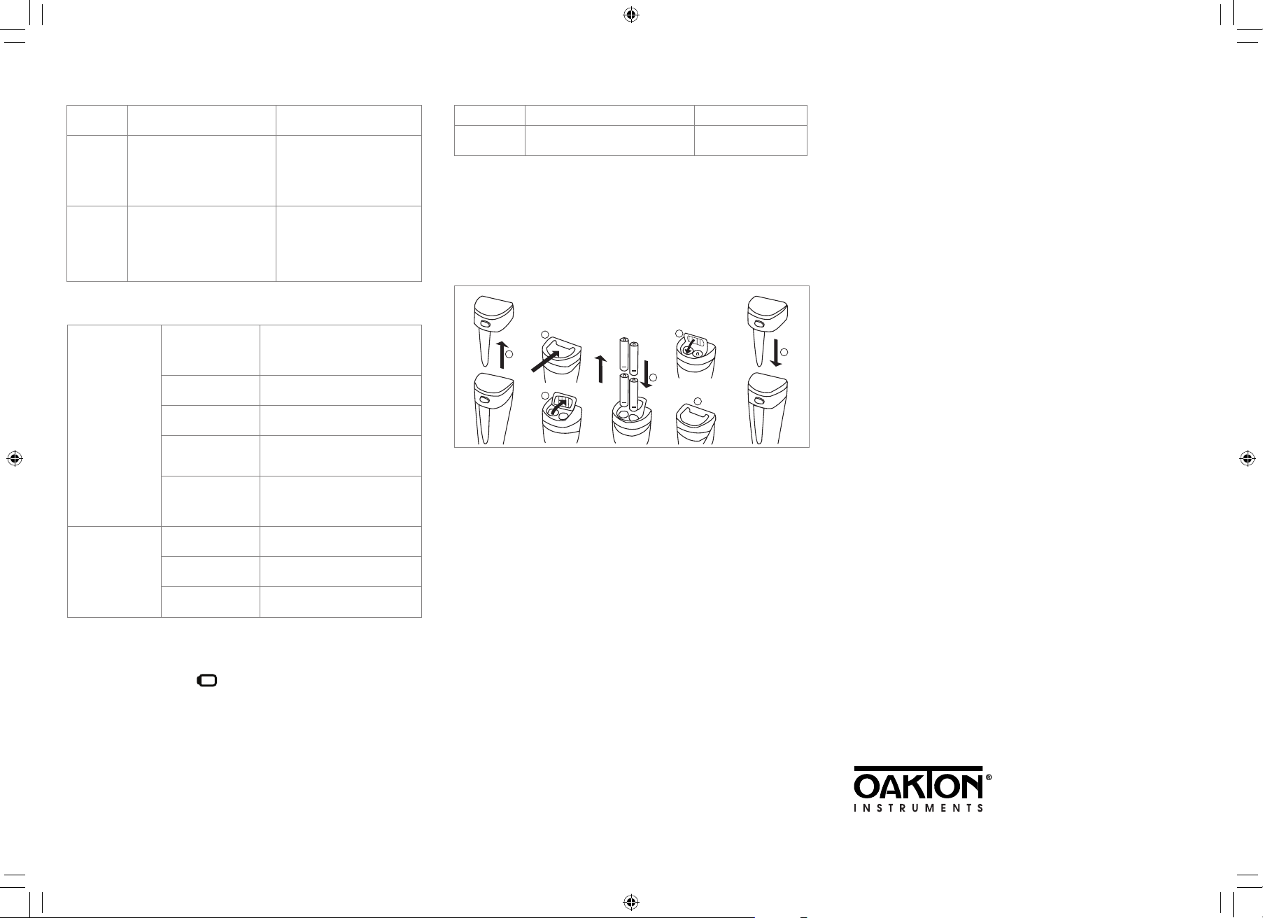
Battery Installation
The tester uses four AAA batteries. Please install batteries
according to the following steps. Note the correct direction
of battery installation: the positive side (+) of every single
battery must face up. Incorrect installation of batteries will
cause damage to the tester and create a potential hazard.
4 x AAA Batteries
2
1
3
+
+
_
_
+
+
_
_
1. Pull the battery cap up.
2. Slide the battery cap along the direction of arrow.
3. Open the battery cap.
4. Insert the batteries (ALL POSITIVE SIDES FACING UP).
5. Close the battery cap.
6. Slide and lock the battery cap along the direction of
arrow.
7. Fit the tester’s cap while making sure to push all the
way down. The tester’s waterproof design may be
compromised if the cap is not fitted correctly.
5
7
4
6
Warranty
We warrant this instrument to be free from defects in
material and workmanship and agrees to repair or replace
free of charge, at option of Oakton Instruments, any
malfunctioned or damaged product attributable to
responsibility of Oakton Instruments, for a period of
two years from the delivery (a six-month limited warranty
applies to probes). This warranty does not apply to defects
resulting from actions such as misuse (violation of the
instructions in this manual or operations in the manner
not specified in this manual), improper maintenance, and
unauthorized repairs. Warranty period is the time limit to
provide free service for the products purchased by
customers, not the service life of the tester or probe.
Oakton Instruments reserves the right to update the
information in this manual without giving notice in
advance.
www.4oakton.com
1065O101_MAN_EC1_35634-06 March 2018
1065O101_MAN_EC1_35634-06.indd 2 03/22/2018 3:49:57 PM
 Loading...