

Page 1
M59
User’s manual
Page 2

Page 3

Thank you.
Dear valued customers,
Thank you for purchasing our product. We are thankful to all our
fans for the continuing support, after just four years since entering the
computer chassis market with the Guardian in 2003, NZXT is now an
established gaming brand and manufacturer of quality hardware in the
market today. Since then, we have stayed true to our goal, which was to
continuously provide innovative next generation products. With every
product, we are still breaking more boundaries and limits. Once again, th ank
you and all NZXT fans for the support and we hope to bring more amazing
products in the coming years.
After you complete your installation, please come by our community forums
at www.nzxt.com/forum
fans from around the world
and voice your opinions with thousands of NZXT
Sincerely,
NZXT Team
NZXT. 1
Page 4

M59 Specifications
Features
• Immense Performance: 5 fan capability (Side 120MM LED fan rear
120mm exhaust included)
• Night light: An ambient light sits over the 5.25” drives to give
visibility in dark rooms or at LAN parties
• Black on Black: Smoked clear window and a black interior gives the
best combination of black on black.
• Meshed front panel allows for more airflow
• 5.25” Stealth bay to keep a clean look
• NZXT Solid State bracket allows for two SSD drives to be installed
Wire Routing: Motherboard punched holes allows for quick CPU
bracket removable and optimal wire routing. Turned HDD also
helps with providing a cleaner look.
• Pre-drilled water cooling holes on the back plate
Front mounted USB, Audio, and E-SATA ports
• Support for external dual radiator at the top of the chassis
• High end graphics card support, the M59 features space that is
especially designed to fit longer 10.5” cards
Detailed specifications
Dimensions (HxWxD): 449mm x 190mm x 508mm
Weight: 6.5 Kg
4 x External 5.25” Bays
7 x Internal HDD bays
Cooling Options:
1 x 120 mm
1 x 120mm Rear Exhaust (included)
1 x 120mm Side Intake LED ( included )
2 x 120/140mm Top exhaust
NZXT. 2
Page 5
g
Table of Contents
Thank you. ..................................................................................... 1
M59 Specifications ......................................................................... 2
Before Beginning.. ......................................................................... 3
Getting starting............................................................................... 3
Motherboard Installation ................................................................ 5
LED, Power and Reset Installation ................................................ 5
External 5.25” Drive Bay Installation ............................................. 7
Internal 3.5” Hard Drive Installation ............................................... 9
Wire routing and CPU fan bracket removal ................................. 13
Support and Service .................................................................... 15
NOTE: CPU, RAM and any peripheral installation are not
included in this manual. Please refer to your motherboard manual
for related mountin
instructions and troubleshooting.
Before Beginning..
For safety issues, it is highly recommended that all users wear
gloves during installation. Also, if you have any questions during
installation, please send an email to service@nzxt.com
proceeding. Thank you.
before
Getting starting
For users building a new system, it is recommended that the side
panels are removed before beginning the installation. The following
steps will outline the steps to remove the top, side panels and the
motherboard tray.
1. Remove the thumb screws securing the side panels.
NZXT. 3
Page 6
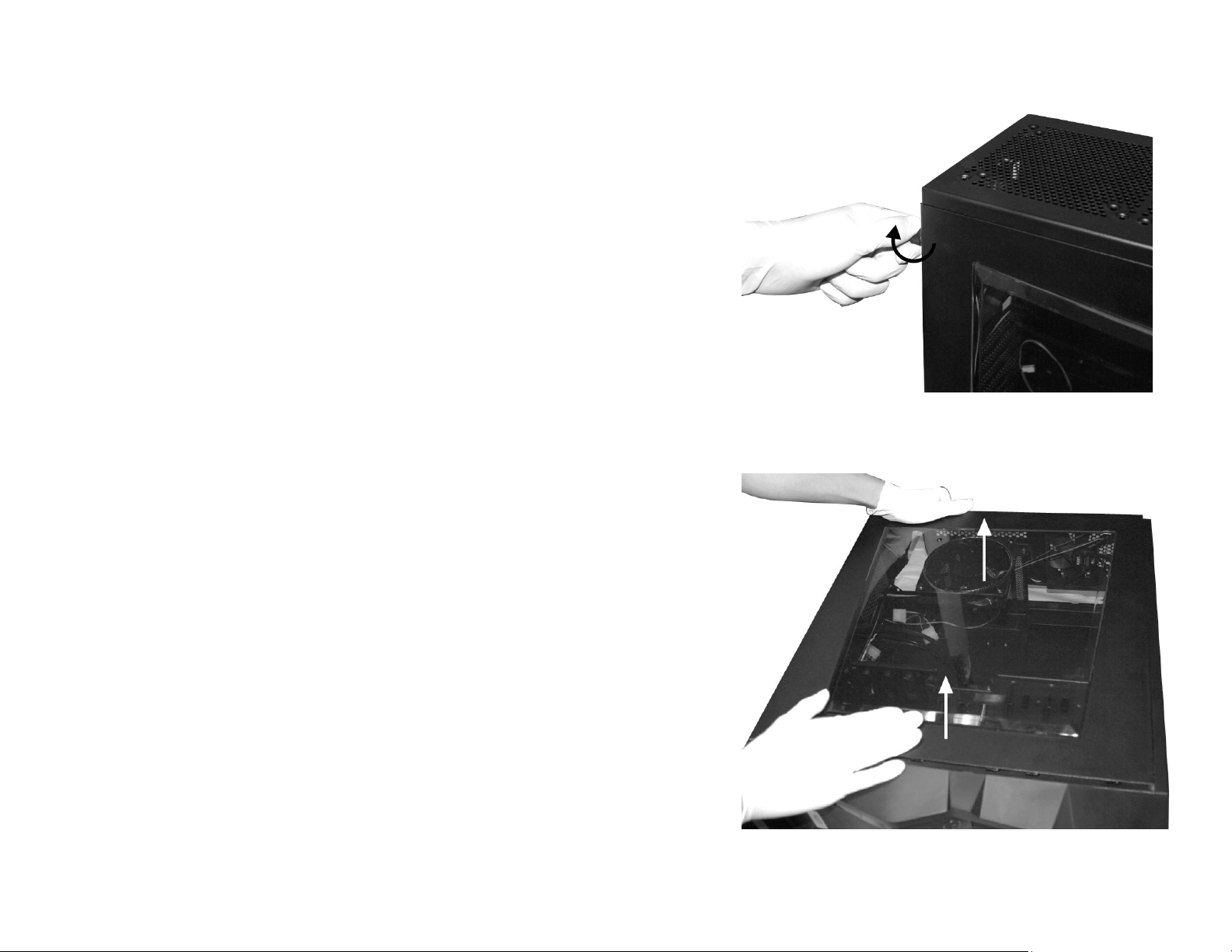
2. Pull the side panel back, and then lift the panel to remove it.
NZXT. 4
Page 7

Motherboard Installation
Please refer to the case interior infrastructure and secure the power
supply at the back of the case by using the screws provided.
1. Match the motherboard form factor ( ATX, M-ATX, MiniATX ) with the holes on the motherboard tray
2. Secure the standoffs onto the holes which match your
motherboard
3. Lay the motherboard onto the standoffs and then
continue to secure the motherboard with the screws
provided.
LED, Power and Reset Installation
Please refer first to your motherboard manual to locate where the
power switch and reset pins are located. The power and reset
buttons are located at the front of the chassis. The colors following
each instruction designate the color of the wires.
1. Connect the reset switch (labeled RESET SW) by
connecting to your motherboard RESET connector. Make
sure you always attach the white wire to ground.
(Purple/Black +/-)
2. Connect the power switch pin (labeled POWER SW) to the
PWR connector on the motherboard. (Yellow/Black +/-)
3. Connect the HDD LED (labeled H.D.D LED) to the
appropriate headers on your motherboard. The HDD LED
located on the front panel should flash Blue when there is
activity in the hard drive. (Green/Black, +/-)
4. Connect the POWER LED(labeled +P LED/-P LED) to the
appropriate headers on your motherboard.(Blue/Black,+/-)
All Black Pin Connectors correspond to ground.
USB Installation
1. The USB is located at the front of the case
NZXT. 5
Page 8

2. Refer to your motherboard manual and match the labels on
the USB port connectors with your motherboard in order to
install.
Audio Port Installation
1. Please first refer to your motherboard manual and match the
labels on the audio wires with your motherboard pins.
2. The green input is the speaker input and the pink input is the
microphone input.
Case Pins Signal Description ASUS© Pins
MIC-IN Front Microphone input Signal MIC2
MIC-POWER Front Microphone Power MICPWR
GROUND Front Audio Ground AGND
L-OUT Front Left Channel Audio Signal Line out_L
R-OUT Front Right Channel Audio Signal Line out_R
L-RET Rear Left Channel Audio Signal
R-RET Rear Right Channel Audio Signal
BLINE Line
out_L
BLINE Line
out_R
NZXT. 6
Page 9

ASUS© Motherboard Pin Assignment
External 5.25” Drive Bay Installation
Please follow the directions below to install the 5.25” in the M59
chassis. In order to use the stealth 5.25” bay for M59, the optical
device must be mounted behind the 5.25” stealth bay.
1. Remove the front panel of the chassis by pulling from the
opening at the bottom of the front panel.
2. Remove the 5.25” black mesh for the 5.25” bay, by pushing
the clips aside
NZXT. 7
Page 10

3. Slide the 5.25” drive in from the front of the
chassis
Insert the 5.25” Device through the opening
4. Match the 5.25” device with the bay and turn the
thumbscrews provided to secure
NZXT. 8
Page 11

Attach the thumbscrews and turn to secure
5. Attach the corresponding amount of thumbscrews to secure
firmly
Internal 3.5” , 2.5” SSD Hard Drive Installation
In order to allow for optimal airflow and better wire management,
M59 allows the user to mount the hard drives towards the
motherboard panel. Please follow the directions below to install the
internal 3.5” HDD devices
1. Open the side panel to gain access inside the chassis
NZXT. 9
Page 12

2. Attach the rails onto the hard drive
3. Slide the bracket back into the cage to secure it
4. If you wish to use the 3.5” external bays to secure the hard
drives, please use the thumbscrews provided
NZXT. 10
Page 13

5. For 2.5” SSD, use the 2.5” to 3.5” bracket provided, the
bracket can fit a total of two 2.5” drives. Similar to the 3.5”
drives, you can attach the rails and slide into the hard drive
cage once the SSD is secure on the bracket.
NZXT. 11
Page 14

6. Lastly, NZXT recommends users route the hard drive power
cables from the back of the motherboard for better airflow
and wire management
NZXT. 12
Page 15

Wire routing and CPU fan bracket removal
The M59 is designed to allow for optimal airflow and wire
management inside the chassis, please follow the guidelines below
on how to use the features.
1. Route PSU cables through the bottom opening and use the
punched holes to tie any loose cables
2. Remove heat sinks easily through the CPU punch-out on the
motherboard tray
NZXT. 13
Page 16

PSU filter removal
In order to remove the filter for the power supply, please unscrew the
four screws at the bottom of the chassis.
NZXT. 14
Page 17

Support and Service
If you have any more questions or have problems with the
NZXT product you purchased, please don’t hesitate to contact
service@nzxt.com
and your proof of purchase. You may inquire about replacement
parts at rma@nzxt.com
Thank you again for purchasing an NZXT case. If you have
any more comments or questions. Please visit our website or send
us an email.
along with a detailed explanation of your problem
.
NZXT Website: www.nzxt.com
Email our design team: designer@nzxt.com
NZXT. 15
 Loading...