

Page 1
LED
USB
POWER
PSU
MB
SATA
USB
SATA
FAN 3
FAN 2
FAN 1
COMPONENT LIST
LISTA DE COMPONENTES
LISTE DES COMPOSANTS
KOMPONENTENLISTE
СПИСОК КОМПОНЕНТОВ
ELENCO DEI COMPONENTI
LISTA DE COMPONENTES
구성품 목록
部品リスト
零件表
零件表
A.
B.
C.
D.
E.
F.
G.
H.
I.
J.
K.
L.
Tempered glass thumb nut
Thumb screw 6-32 x 6mm
Special thumb screw 6-32 x 6mm
Hexagon screw 6-32 x 6mm
Screw 6-32 x 5mm
Screw M3 x 5mm
Screw KB5 x 10mm
Standoff 6-32 x 6.5+4mm
Standoff wrench
Cable tie
GPU stand
Breakout Cable
Tempered glass installation
Extension slots installation
Side panel, Front fan braket, SSD bracket
Power supply installation
Motherboard installation, 3.5 hard drive installation
2.5 hard drive installation
Fan installation
Motherboard installation
Motherboard installation
Cable management
GPU installation
For Non-Intel Standard F_Panel Header Use
A.
B.
C.
D.
E.
F.
G.
H.
I.
J.
K.
L.
Pouce écrou
Vis à serrage à main 6-32 x 6 mm
Vis à serrage à main spéciale 6-32 x 6 mm
Vis hexagonale 6-32 x 6 mm
Vis 6-32 x 5 mm
Vis M3 x 5 mm
Vis KB5 x 10 mm
Entretoise 6-32 x 6,5 + 4 mm
Clé pour entretoise
Attache-câble
Support du GPU
Câble multi connexions
Mise en place du panneau en verre trempé
Plateau disque dur 2,5’’, installation des emplacements d'extension
Panneau latéral, Support d'alimentation électrique, Plateau disque dur
Installation de l'alimentation électrique
Installation de la carte mère, installation du disque dur 3,5’’
Installation du disque dur 2,5’’
Installation du ventilateur
Installation de la carte mère
Installation de la carte mère
Gestion du câblage
Installation du GPU
Pour le connecteur Front Panel de cartes mères non-intel
A.
B.
C.
D.
E.
F.
G.
H.
I.
J.
K.
L.
барашковая гайка
Винт с барашком 6-32 х 6 мм
Специальный винт с барашком 6-32 х 6 мм
Винт шестигранный 6-32 х 6 мм
Винт 6-32 х 5 мм
Винт M3 х 5 мм
Винт КВ5 х 10 мм
Стойка 6-32 х 6,5 + 4 мм
Гаечный ключ
Кабельный хомут:
Подставка для графического процессора
Кабель-разветвитель
Установка закаленного стекла
Установка лотка для жестких дисков 2,5'', разъемов расширения
Боковая панель, кронштейн для источника питания, лоток для жестких дисков
Установка источника питания
Установка материнской платы, установка жесткого диска 3,5''
Установка жесткого диска 2,5''
Установка вентилятора
Установка материнской платы
Установка материнской платы
Организация кабельных систем
Установка графического процессора
Для подключения фронтальной панели к материнским платам с разъёмами
не-Intel стандарта
A.
B.
C.
D.
E.
F.
G.
H.
I.
J.
K.
L.
엄지 손가락 너트
나비나사 6-32 x 6mm
특수 나비나사 6-32 x 6mm
육각나사 6-32 x 6mm
나사 6-32 x 5mm
나사 M3 x 5mm
나사 KB5 x 10mm
스탠드오프 6-32 x 6.5+4mm
스탠드오프 렌치
케이블 타이
GPU 스탠드
브레이크아웃 케이블
강화 유리 설치
2.5 하드 드라이브 트레이, 확장 슬롯 설치
사이드 패널, 전원공급장치 브래킷, HDD 트레이
전원공급장치 설치
마더보드 설치, 3.5 하드 드라이브 설치
2.5 하드 드라이브 설치
팬 설치
마더보드 설치
마더보드 설치
케이블 정리
GPU 설치
비 인텔 표준 메인보드 F-패널(전면 패널) 헤더 용
A.
B.
C.
D.
E.
F.
G.
H.
I.
J.
K.
L.
強化ガラスつまみナット
ツマミネジ6-32 x 6mm
特製ツマミネジ6-32 x 6mm
6角ネジ6-32 x 6mm
ネジ6-32 x 5mm
ネジ M3 x 5mm
ネジKB5 x 10mm
スタンドオフ6-32 x 6.5+4mm
スタンドオフ レンチ
ケーブルタイ
GPU スタンド
ブレークアウトケーブル
強化ガラス取り付け
2.5HDDトレイ、拡張スロット装着用
サイドパネル、電源ブラケット、HDDトレイ固定用
電源装着用
マザーボード装着、3.5HDD装着用
2.5HDD装着
ファン装着用
マザーボード装着用
マザーボード装着用
ケーブル整理用
GPU 取り付け
MBのF-PanelヘッダがIntel標準ではない場合
A.
B.
C.
D.
E.
F.
G.
H.
I.
J.
K.
L.
钢化玻璃指旋螺母
指旋螺丝 6-32 x 6mm
特制指旋螺丝
六角螺丝 6-32 x 6mm
螺丝 6-32 x 5mm
螺丝 M3 x 5mm
螺丝 KB5 x 10mm
脚柱 6-32 x 6.5+4mm
脚柱套筒板手
束线带
GPU 支架
分接线
钢化玻璃安装
2.5 硬碟托盘, 扩充槽安装
侧板, 电源支架
安装电源
3.5 硬盘安装, 主板安装
2.5 硬盘安装
安装风扇
主板安装
主板安裝
线缆管理
GPU 安装
用于非英特尔标准主板前版接口
A.
B.
C.
D.
E.
F.
G.
H.
I.
J.
K.
L.
鋼化玻璃手轉螺母
指旋螺絲 6-32 x 6mm
特製指旋螺絲
六角螺絲 6-32 x 6mm
螺絲 6-32 x 5mm
螺絲 M3 x 5mm
螺絲 KB5 x 10mm
腳柱 6-32 x 6.5+4mm
腳柱套筒板手
束線帶
GPU 底座
分接線
強化玻璃安裝
2.5 硬碟托盤, 擴充槽安裝
側板, 電源支架
安裝電源
3.5 硬碟安装, 主機板安装
2.5 硬碟安装
安裝風扇
主板安装
主板安裝
線纜管理
GPU 安裝
用於非英特爾標準主板前版接頭
A.
B.
C.
D.
E.
F.
G.
H.
I.
J.
K.
L.
Flügelmutter
Rändelschraube 6 – 32 x 6 mm
Spezielle Rändelschraube 6 – 32 x 6 mm
Sechskantschraube 6 – 32 x 6 mm
Schraube 6 – 32 x 5 mm
Schraube M3 x 5 mm
Schraube KB5 x 10 mm
Abstandhalter 6 – 32 x 6,5 + 4 mm
Abstandhalter-Schlüssel
Kabelbinder
GPU-Ständer
Kabelpeitsche
Installation des Hartglasfensters
2,5-Zoll-Festplatteneinschub, Installation von Erweiterungssteckplätzen
Seitenblende, Netzteilhalterung, Festplattenfach
Netzteilinstallation
Motherboard-Installation, 3,5-Zoll-Festplatteninstallation
2,5-Zoll-Festplatteninstallation
Lüfterinstallation
Motherboard-Installation
Motherboard-Installation
Kabelverwaltung
GPU-Installation
Front Panel Header für alle gängigen nicht-Intel Mainboards
A.
B.
C.
D.
E.
F.
G.
H.
I.
J.
K.
L.
Dado pollice
Viti a testa zigrinata 6-32 x 6 mm
Vite a testa zigrinata speciale 6-32 x 6 mm
Vite esagonale 6-32 x 6 mm
Vite 6-32 x 5 mm
Vite M3 x 5 mm
Vite KB5 x 10 mm
Distanziatore 6-32 x 6,5 + 4 mm
Chiave per distanziatori
Fascetta per cavi
Supporto GPU
Cavo multiconnessione
Installazione vetro temperato
2.5 Cassetto HDD, installazione alloggi d’espansione
Pannello laterale, staffa alimentatore, cassetto HDD
Installazione dell’alimentatore
Installazione della scheda madre, installazione HDD 3.5”
Installazione HDD 2.5”
Installazione della ventola
Installazione della scheda madre
Installazione della scheda madre
Gestione dei cavi
Installazione della GPU
Connettore F-Panel per Mainboard non Intel
A.
B.
C.
D.
E.
F.
G.
H.
I.
J.
K.
L.
Porca de polegar
Parafusos borboleta 6-32 x 6 mm
Parafusos de borboleta 6-32 x 6 mm
Parafusos hexagonal 6-32 x 6 mm
Parafusos 6-32 x 5 mm
Parafusos M3 x 5 mm
Parafusos KB5 x 10 mm
Separadores 6-32 x 6,5+4 mm
Chave para separador
Braçadeira para cabos
Suporte da GPU
Cabo divisor
Instalação do vidro temperado
tabuleiro da unidade de 2,5", instalação das ranhuras de extensão
painel lateral, suporte da fonte de alimentação, tabuleiro de HDD
instalação da fonte de alimentação
instalação da placa principal, instalação da unidade de 3,5"
instalação da unidade de 2,5"
instalação da ventoinha
instalação da placa principal
instalação da placa principal
Gestão de cabos
Instalação da GPU
Para ligação do painel frontal (F-Panel) em placa-mãe padrão não-Intel
A.
B.
C.
D.
E.
F.
G.
H.
I.
J.
K.
L.
Tuerca de mariposa
Tornillo de apriete manual de 6-32 x 6 mm
Tornillo de apriete manual especial
de 6-32 x 6 mm
Tornillo hexagonal de 6-32 x 6 mm
Tornillo de 6-32 x 5 mm
Tornillo M3 x 5mm
Tornillo KB5 x 10 mm
Separador 6-32 x 6,5 +4 mm
Llave para separadores
Brida para cables
Soporte de la GPU
Cable multiconector
Instalación de vidrio templado
bandeja de unidad de disco duro de 2,5" e instalación de ranuras de extensión
panel lateral, soporte de fuente de alimentación y bandeja para unidad
de disco duro
instalación de la fuente de alimentación
instalación de la placa base e instalación de la unidad de disco duro de 3,5"
instalación de la unidad de disco duro de 2,5"
instalación del ventilador
instalación de la placa base
instalación de la placa base
Administración de los cables
Instalación de la GPU
Para panel frontal de placas base no Intel.
x7
Installed x7
Accessory Box x0
C
Special thumb screw 6-32 x 6mm
x10
Installed x4
Accessory Box x6
D
Hexagon screw 6-32 x 6mm
x8
Installed x0
Accessory Box x8
E
Screw 6-32 x 5mm
x16
Installed x0
Accessory Box x16
F
Screw M3 x 5mm
A
x4
Installed x4
Accessory Box x0
Tempered glass thumb nut
x16
Installed x8
Accessory Box x8
G
Screw KB5 x 10mm
x4
Installed x4
Accessory Box x0
H
Standoff 6-32 x 6.5+4mm
x1
Installed x0
Accessory Box x1
I
Standoff wrench
x10
Installed x0
Accessory Box x10
J
Cable tie
x1
Installed x0
Accessory Box x1
K
GPU Stand
x4
Installed x4
Accessory Box x0
B Thumb screw 6-32 x 6mm
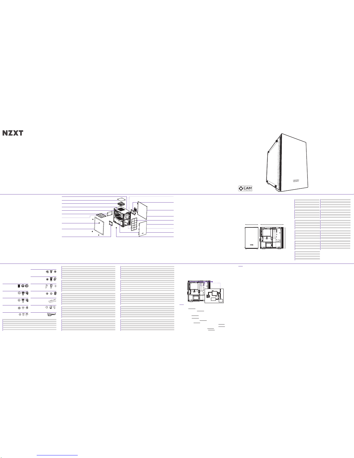
MINI-ITX CASE
H200i / H200
CLEARANCES AND SPECIFICATIONS
MEDIDAS Y ESPECIFICACIONES
DÉGAGEMENTS ET SPÉCIFICATIONS
ABSTÄNDE UND TECHNISCHE DATEN
ТЕХНИЧЕСКИЕ ХАРАКТЕРИСТИКИ И ЗАЗОРЫ
SPAZI NECESSARI E SPECIFICHE
DIMENSÕES E ESPECIFICAÇÕES
간격과 규격
空間と仕様
间距与规格
間距與規格
主板支援:
2.5’’SSD支援
3.5’’HDD支援
擴充槽
GPU 間距
線纜管理
CPU 散熱器間距
前面散熱氣
Mini-ITX
3+1
1
2
325mm
15.9mm
165mm
85mm
主板支持:
2.5’’SSD支持
3.5’’HDD支持
扩充槽
GPU 间距
线缆管理
CPU 散热器间距
前面散热气
Mini-ITX
3+1
1
2
325mm
15.9mm
165mm
85mm
マザーボードサポート
2.5’’SSDサポート
3.5’’HDDサポート
エクスパンションスロット
GPUクリアランス
ケーブルの管理
CPUクーラークリアランス
フロントラジエーター
Mini-ITX
3+1
1
2
325mm
15.9mm
165mm
85mm
Поддержка материнской платы
для твердотельных накопителей 2,5"
для жестких дисков 3,5"
Разъемы расширения
Зазор для графического процессора
Организация кабельных систем
Кулер процессора
Передний радиатор
Mini-ITX
3+1
1
2
325mm
15.9mm
165mm
85mm
Placa-principais suportadas
SSD de 2,5"
HDD de 3,5”
Ranhuras de expansão
Folga para a GPU
Gestão de cabos
Dissipador de CPU
Radiador frontal
Mini-ITX
3+1
1
2
325mm
15.9mm
165mm
85mm
마더보드 지원
2.5" SSD
3.5" HDD
확장 슬롯
GPU 간격
케이블 정리
CPU 쿨러
앞쪽 라디에이터
Mini-ITX
3+1
1
2
325mm
15.9mm
165mm
85mm
Cartes mère prises en charge
SSD 2,5’’
Disques durs 3,5’’
Baies d'extension
Longueur du GPU
Gestion du câblage
Radiateur du processeur
Radiateur avant
Mini-ITX
3+1
1
2
325mm
15.9mm
165mm
85mm
Placas base admitidas
Unidad de estado sólido de 2,5’’
Unidad de disco duro de 3,5”
Ranuras de expansión
Distancia de seguridad para GPU
Administración de los cables
Disipador de la CPU
Radiador frontal
Mini-ITX
3+1
1
2
325mm
15.9mm
165mm
85mm
Motherboard Support
2.5” SSD Support
3.5” HDD Support
Expansion Slots
GPU Clearance
Cable Management
CPU Cooler Clearance
Front Radiator
Mini-ITX
3+1
1
2
325mm
15.9mm
165mm
85mm
EXPLODED VIEW
VISTA EXPLOSIONADA
VUE EN ÉCLATÉ
EXPLOSIONSDARSTELLUNG
ТРЕХМЕРНОЕ ПРЕДСТАВЛЕНИЕ ДЕТАЛЕЙ
VEDUTA IN ESPLOSO
VISTA EXPLODIDA
확대도
展開図
部件分解图
部件分解圖
1.
2.
3.
4.
5.
6.
7.
8.
9.
10.
11.
12.
13.
14.
15.
16.
17.
18.
19.
섀시
상단 필터
상단 배기팬
상단 RGB LED 스트립
후면 배기팬
SFX PSU 브래킷
PSU 먼지 필터
좌측 강화 유리 패널
좌측 강화 유리 사이드 패널
SSD 트레이
전면 I/O
SSD 브래킷
스마트 장치 (H200i)
우측 메탈 패널
전면 먼지 필터
전면 베젤
전면 쿨러 브래킷
케이블 정리 바
GPU 스탠드
1.
2.
3.
4.
5.
6.
7.
8.
9.
10.
11.
12.
13.
14.
15.
16.
17.
18.
19.
シャーシ
上部フィルタ
トップ排出ファン
トップ RGB LED ストリップ
リア排出ファン
SFX PSU ブラケット
PSU ダストフィルター
左強化ガラスパネル
左サイド強化ガラスパネル
SSDトレイ
フロント I/O
SSD ブラケット
スマートデバイス (H200i)
右サイド金属パネル
フロントダストフィルター
フロントベゼル
フロントクーラーブラケット
クリーン保持具
GPU スタンド
1.
2.
3.
4.
5.
6.
7.
8.
9.
10.
11.
12.
13.
14.
15.
16.
17.
18.
19.
机箱
上部滤网
顶部排气扇
顶部 RGB LED 灯带
后排气扇
SFX PSU 支架
PSU 防尘过滤器
钢化玻璃指旋螺母
左侧钢化玻璃板
硬盘架
前端 I/O
SSD 支架
智能设备 (H200i)
右侧金属板
前端灰尘过滤器
前挡板
前端冷却器支架
理线档板
GPU 支架
1.
2.
3.
4.
5.
6.
7.
8.
9.
10.
11.
12.
13.
14.
15.
16.
17.
18.
19.
機殼
上部濾網
頂部排風風扇
頂部 RGB LED 燈條
後方排風風扇
SFX 電源供應器架
電源供應器防塵濾網
鋼化玻璃手轉螺母
左側強化玻璃面板
硬盤架
前方 I/O
SSD 架
智慧裝置 (H200i)
右側金屬面板
前方防塵過濾網
前面板
前方散熱器架
理線檔板
GPU 底座
Chasis
Filtro superior
Ventilador de escape superior
Tira LED RGB superior
Ventilador de escape trasero
Soporte de la PSU SFX
Filtro de polvo de la PSU
Panel de cristal templado izquierdo
Panel de vidrio templado lateral izquierdo
Bandeja unidad de estado sólido
E/S frontal
Soporte para SSD
Dispositivo inteligente (H200i)
Panel metálico derecho
Filtro de polvo frontal
Bisel frontal
Soporte del refrigerador frontal
Barra de limpieza
Soporte de la GPU
1.
2.
3.
4.
5.
6.
7.
8.
9.
10.
11.
12.
13.
14.
15.
16.
17.
18.
19.
SMART DEVICE (H200i)
DISPOSITIVO INTELIGENTE
APPAREIL INTELLIGENT
SMART DEVICE
ИНТЕЛЛЕКТУАЛЬНОЕ УСТРОЙСТВО
DISPOSITIVO INTELLIGENTE
DISPOSITIVO INTELIGENTE
스마트 장치
スマートデバイス
智能设备
智慧裝置
The Smart Device connects to your PC via a single internal USB 2.0 connector. To enable control of the Smart Device, download
and install CAM from camwebapp.com.
FAN CONNECTORS - Three Fan connectors for three channels. To attach additional fans, use the included fan splitters.
Note: The first fan connector with 4 pins on the fan splitter will be the primary fan. Do not mix PWM or 3-pin fans.
Note: To most effectively use CAM’s smart Adaptive Noise Reduction, you should connect your CPU fan to the Smart Device. If you
choose to do this, you will need to disable the CPU Fan warning in your motherboard’s BIOS settings.
RGB LED CONNECTOR - One LED strip is integrated inside the case. Connect additional HUE+ LED strips via the end connector located
on the bottom LED strip. To connect Aer RGB, connect directly to the RGB LED connector.
POWER CONNECTOR - Connect to the power supply to power on the smart device, fans, and LED strips.
Note: Do not connect while PC is powered on.
CONECTORES DE VENTILADOR - Tres conectores de ventilador para tres canales. Para conectar ventiladores adicionales, utiliza los
cables bifurcadores para ventilador incluidos.
Nota: El primer conector de ventilador con 4 patillas del cable bifurcador para ventilador será el ventilador principal. No mezcle
ventiladores PWM y de 3 patillas.
Nota: Para utilizar la reducción de ruido adaptativa inteligente de CAM de la forma más eficaz, debes conectar el ventilador de la CPU al
dispositivo inteligente. Si decides hacerlo, deberás desactivar la advertencia del ventilador de la CPU en la configuración de la BIOS de
la placa base.
CONECTOR LED RGB - Hay una tira de LED integrada en el interior de la caja. Conecta tiras LED HUE+ adicionales mediante el conector
final ubicado en la tira de LED inferior. Para conectar Aer RGB, conéctalos directamente al conector LED RGB.
CONECTOR DE ALIMENTACIÓN - Conéctalo a la fuente de alimentación para alimentar el dispositivo inteligente, los ventiladores y las
tiras de LED.
Nota: No lo conectes mientras el PC esté encendido.
CONNECTEURS DE VENTILATEUR - Trois connecteurs de ventilateur pour trois canaux. Pour installer d'autres ventilateurs, utilisez les
répartiteurs fournis.
Remarque: le ventilateur branché au premier connecteur de ventilateur à 4broches du répartiteur de ventilateur est le ventilateur
principal. Ne pas brancher les ventilateurs PWM et les modèles à 3broches sur le même canal.
Remarque: Pour profiter au maximum du système de réduction intelligente de bruit du CAM, vous devez relier le ventilateur de votre
processeur au Smart Device. Dans ce cas, vous devrez désactiver l'avertissement d'absence de ventilateur du processeur dans les
paramètres BIOS de votre carte mère.
CONNECTEUR LED RGB - Une bande LED est intégrée au boîtier. Connectez d'autres bandes LED HUE+ via le connecteur situé sur la
bande LED inférieure. Pour connecter Aer RGB, branchez directement au connecteur LED RGB.
CONNECTEUR D'ALIMENTATION - Branchez à l'alimentation pour alimenter le Smart Device, les ventilateurs et les bandes LED.
Remarque: ne pas brancher lorsque l'ordinateur est sous tension.
LÜFTERANSCHLÜSSE - Drei Lüfteranschlüsse für drei Kanäle. Weitere Lüfter können über die im Lieferumfang enthaltenen
Lüfter-Splitter angeschlossen werden.
Hinweis: Der erste 4-polige Lüfteranschluss am Lüfter-Splitter ist der primäre Lüfter- PWM und 3-polige Lüfter dürfen nicht über
denselben Kanal kombiniert werden.
Hinweis: Für den effizienten Einsatz der intelligenten Adaptive Noise Reduction am CAM sollten Sie den CPU-Lüfter mit dem Smart
Device verbinden. Sie müssen dazu die CPU-Lüfterwarnung in den BIOS-Einstellungen des Mainboards deaktivieren.
RGB-LED-STECKVERBINDER - Ein LED-Streifen ist in das Gehäuse integriert. Weitere HUE+ LED-Streifen können über den
Endverbinder am unteren LED-Streifen angeschlossen werden. Weitere Aer RGB können direkt über den RGB-LED-Steckverbinder
angeschlossen werden.
STROMANSCHLUSS - Schließen Sie das Netzteil an, um das Smart Device, die Lüfter und die LED-Streifen einzuschalten.
Hinweis: Nicht anschließen, während der PC eingeschaltet ist.
CONNETTORI VENTOLE - Tre connettori ventole per tre canali. Per fissare le ventole aggiuntive, utilizzare gli splitter ventole inclusi.
Nota: il primo connettore ventole con 4 pin sullo splitter ventola sarà la ventola principale. Non mischiare ventole PWM e ventole a 3 pin
nello stesso canale.
Nota: per utilizzare in maniera più efficace la riduzione del rumore adattiva di CAM, si consiglia di connettere la ventola CPU al
dispositivo intelligente. Se si sceglie questa opzione, è necessario disattivare l'avviso relativo alla ventola CPU nelle impostazioni BIOS
della scheda madre.
CONNETTORE LED RGB - Una striscia LED è integrata nel case. Collegare i nastri LED HUE+ aggiuntivi al connettore finale posizionato
sul nastro LED inferiore. Per collegare la ventola Aer RGB, collegarla direttamente al connettore LED RGB.
CONNETTORE DI ALIMENTAZIONE - Collegare l'alimentazione per accendere il dispositivo intelligente, le ventole e i nastri LED.
Nota: non effettuare il collegamento se il PC è acceso.
Le Smart Device se connecte à votre PC via un seul port USB2.0 interne. Pour activer le Smart Device, veuillez télécharger CAM
sur camwebapp.com.
Das Smart Device wird über den internen USB2.0-Anschluss mit Ihrem PC verbunden. Um die Steuerung des Smart Device zu
aktivieren, einfach CAM über camwebapp.com herunterladen und installieren.
Il dispositivo intelligente si collega al PC tramite un connettore USB 2.0 singolo interno. Per abilitare il controllo del dispositivo,
scaricare e installare CAM da camwebapp.com.
O dispositivo inteligente se conecta a seu computador por um conector USB 2.0 interno simples. Para habilitar o controle do
dispositivo inteligente, baixe e instale o CAM em camwebapp.com.
이 스마트 장치는 단일 내부 USB 2.0 커넥터를 통해 PC에 연결됩니다. 스마트 장치의 제어 기능을 사용하려면 camwebapp.com에서 CAM을
다운로드하고 설치하십시오.
スマートデバイスは、内蔵 USB 2.0 コネクタ 1 つで PC に接続します。スマートデバイスを制御するには、camwebapp.com から CAM をダ
ウンロードしてインストールしてください。
智能设备通过单个 USB 2.0 接口连接到您的计算机。要想控制智能设备,请从 camwebapp.com 下载并安装 CAM。
智慧裝置透過一個內部的 USB 2.0 連接器連接至電腦。若要控制智慧裝置,請至 camwebapp.com 下載並安裝 CAM。
Интеллектуальное устройство подключается к ПК через внутренний портUSB2.0 Для управления интеллектуальным устройством
загрузите и установите CAM с сайта camwebapp.com.
El dispositivo inteligente se conecta a tu PC mediante un único conector USB 2.0 interno. Para activar el control del dispositivo
inteligente, descarga e instala CAM desde camwebapp.com.
SMART DEVICE
PORTS
CONECTORES DE VENTOINHA - Três conectores de ventoinhas para três canais. Para conectar ventoinha adicionais, utilize os divisores
para ventoinha incluídos.
Nota: O primeiro conector de ventoinha com 4 pinos no divisor para ventoinha será a ventoinha primária. Não misture ventoinhas PWM
ou 3 pinos.
Nota: Para usar a redução adaptável de ruído inteligente da CAM, você deve conectar a ventoinha da CPU ao dispositivo inteligente.
Se você escolher fazer isso, será necessário desabilitar o alerta da ventoinha da CPU nas configurações BIOS da placa-mãe.
CONECTOR RGB DE LED - Uma tira de LED é intregrada à parte interna do gabinete. Conecte as faixas de LED HUE+ adicionais pelo
conector final localizado na parte inferior da faixa de LED. Para conectar o Aer RGB, conecte diretamente o conector LED RGB.
CONECTOR DE ALIMENTAÇÃO - Conecte a fonte de alimentação à alimentação do dispositivo inteligente, às ventoinhas e às faixas de
LED.
Nota: Não conecte enquanto o computador estiver ligado.
Разъемы вентиляторов - Три разъема вентиляторов для трех каналов. Чтобы присоединить дополнительные вентиляторы, воспользуйтесь
разветвительными кабелями для вентиляторов (в комплекте).
Примечание. Первый 4-контактный разъем разветвительного кабеля предназначен для основного вентилятора. Не используйте PWM и
3-контактные вентиляторы на одном канале.
Примечание. Для максимально эффективного использования интеллектуальной функции адаптивного шумоподавления CAM необходимо
подключить вентилятор ЦП к интеллектуальному устройству. Если вы решите это сделать, необходимо будет отключить предупреждение
вентилятора ЦП в настройках BIOS материнской платы.
Светодиодный разъем (RGB) - Одна светодиодная лента встроена внутрь корпуса. Подсоедините дополнительные светодиодные ленты HUE+ к
разъему, расположенному на конце светодиодной ленты. Чтобы подключить Aer RGB, подсоедините его напрямую к светодиодному разъему (RGB).
Разъем питания - Чтобы включить интеллектуальное устройство, вентиляторы и светодиодные ленты, подключите их к блоку питания.
Примечание. Не подключайте, если ПК включен.
팬 커넥터 - 3개 채널을 탑재했으며, 각 채널별로 3개의 팬 커넥터가 있습니다. 다른 팬을 추가로 설치하려면 포함된 팬 스플리터를 사용하십시오.
참고: 팬 스플리터에 핀 4개가 있는 첫 번째 팬 커넥터가 기본 팬입니다. PWM과 3핀 팬을 혼용하지 마십시오.
참고: CAM의 스마트한 적응형 노이즈 감소 기능을 효율적으로 사용하려면 CPU 팬을 스마트 장치에 연결해야 합니다. CPU 팬을 스마트 장치에 연결할
경우, 마더보드의 BIOS 설정에서 CPU 팬 경고 기능을 비활성화해야 할 수도 있습니다.
RGB LED 커넥터 - LED 스트립 1개가 케이스 내부에 내장되어 있습니다. 하부 LED 스트립에 위치한 엔드 커넥터를 통해 추가 HUE+ LED 스트립을 연
결하십시오. Aer RGB를 연결하려면 RGB LED 커넥터에 직접 연결하십시오.
전원 커넥터 - 전원 공급 장치에 연결하여 스마트 장치, 팬, LED 스트림에 전원을 공급합니다.
참고: PC 전원이 켜져 있는 동안에는 연결하지 마십시오.
ファンコネクタ - 3 つのチャネル用に 3 つのファンコネクタがあります。追加のファンを取り付けるには、付属のファンスプリッタを使用してください。
注:ファンスプリッタの最初の 4 ピンファンコネクタがプライマリファンになります。同じチャネルに PWM ファンと 3 ピンファンを混在させないでください。
注:CAM のスマート自動ノイズ低減機能を最も効果的に使用するには、CPU ファンをスマートデバイスに接続する必要があります。接続する場合は、マザーボ
ードの BIOS 設定で CPU ファンの警告を無効にする必要があります。
RGB LED コネクタ - 1 本の LED ストリップがケース内に統合されています。追加の HUE+ LED ストリップは、ボトム LED ストリップにあるエンドコ
ネクタで接続してください。Aer RGB を接続するには、RGB LED コネクタに直接接続してください。
電源コネクタ - スマートデバイス、ファン、LED ストリップに電源を供給するには、電源に接続してください。
注:PC の電源がオンの間は接続しないでください。
风扇接头 - 三个风扇接头,用于三个通道。要连接额外的风扇,请使用随附的风扇转接线。
注:风扇分频线上第一个 4 针风扇接头将用于主风扇。在同一通道请勿混淆 PWM 或 3 针风扇。
注:为了更有效地使用 CAM 的智能自适应降噪功能,您应该将 CPU 风扇连接到智能设备上。如果选择这样做,您应该在主板的 BIOS 设置中禁用 CPU 风
扇警告。
RGB LED 接头 - 一条 LED 灯带已集成在机箱内。请通过底部 LED 灯带上的端接器连接额外的 HUE+ LED 灯带。要连接 Aer RGB,请直接连接至 RGB LED 接头。
电源接头 - 连接到电源,让智能设备、风扇和 LED 灯带通电。
注:请勿在计算机通电状态下进行连接。
風扇連接器 - 三個風扇連接器供三個通道使用。若要連接額外的風扇,請使用隨附的風扇分線器。
備註︰風扇分線器上的第一個 4 針腳風扇連接器將是主要風扇。請勿在同一個通道中混用 PWM 或 3 針腳風扇。
備註︰若要以最有效的方式使用 CAM 的自主適應降噪功能,您應將 CPU 風扇連接到智慧型裝置。若選擇這樣做,您必須停用主機板 BIOS 設定中的 CPU
風扇警告。
RGB LED 接頭 - 機殼內建一條 LED 燈條。透過底部 LED 燈條的端點接頭,即可連接額外的 HUE+ LED 燈條。若要連接 Aer RGB,請直接連接至
RGB LED 接頭。
電源連接器 - 連接至電源供應器,為智慧裝置、風扇及 LED 燈條供電和啟用。
備註︰電腦電源開啟時,請勿連接。
Motherboard-Unterstützung
2,5-Zoll-SSD
3,5-Zoll-Festplatte
Erweiterungssteckplätze
GPU-Abstand
Kabelverwaltung
CPU-Kühler
Vorderer Kühlkörper
Mini-ITX
3+1
1
2
325mm
15.9mm
165mm
85mm
Scheda madre supportata
SDD 2.5”
HDD 3.5”
Alloggi d’espansione
Spazio necessario alla GPU
Gestione dei cavi
Dispersore di calore CPU
Radiatore frontale
Mini-ITX
3+1
1
2
325mm
15.9mm
165mm
85mm
210MM 372MM
349MM
Châssis
Filtre à poussière du haut
Ventilateur en extraction du haut
Bande LED RVB du dessus
Ventilateur d'échappement arrière
Support du bloc d'alimentation SFX
Filtre à poussière du bloc d'alimentation
Vis à serrage à main pour le panneau en verre trempé
Panneau latéral gauche en verre trempé
Plateau SSD
E/S avant
Support du SSD
Smart Device (H200i)
Panneau métallique droit
Filtre à poussière avant
Cache avant
Support du dissipateur avant
Barre pour la gestion des câbles
Support du GPU
1.
2.
3.
4.
5.
6.
7.
8.
9.
10.
11.
12.
13.
14.
15.
16.
17.
18.
19.
Gehäuse
Top Filter
Lüfter für Luftauslass an Oberseite
RGB-LED-Streifen an Oberseite
Lüfter für Luftauslass an Rückseite
SFX-Netzteilhalterung
Netzteil-Staubfilter
Linke Hartglasblende
Hartglasfenster links
SSD-Fach
E/A an der Vorderseite
SSD-Halterung
Smart Device (H200i)
Seitliche Abdeckung rechts aus Metall
Staubfilter an Vorderseite
Einfassung an Vorderseite
Kühlerhalterung an Vorderseite
Reinigungsleiste
GPU-Ständer
1.
2.
3.
4.
5.
6.
7.
8.
9.
10.
11.
12.
13.
14.
15.
16.
17.
18.
19.
Chassis
Filtro superiore
Ventola di scarico superiore
Striscia LED RGB superiore
Ventola di scarico posteriore
Staffa alimentatore SFX
Filtro polvere alimentatore
Pannello laterale sinistro di vetro temperato
Pannello laterale sinistro in vetro temperato
Cassetto SDD
I/O anteriore
Staffa SSD
Dispositivo intelligente (H200i)
Pannello destro in metallo
Filtro polvere anteriore
Smussatura anteriore
Staffa raffreddamento anteriore
Barra di gestione dei cavi
Supporto GPU
1.
2.
3.
4.
5.
6.
7.
8.
9.
10.
11.
12.
13.
14.
15.
16.
17.
18.
19.
Chassi
Filtro de topo
Ventoinha de exaustão da parte superior
Tira de LED RGB da parte superior
Ventoinha de exaustão traseira
Suporte do PSU SFX
Filtro de pó do PSU
Painel esquerdo em vidro temperado
Vidro temperado do painel lateral esquerdo
Tabuleiro de SSD
E/S frontal
Suporte do SSD
Dispositivo inteligente (H200i)
Painel de metal direito
Filtro de pó frontal
Moldura frontal
Suporte da ventoinha frontal
Barra de limpeza
Suporte da GPU
1.
2.
3.
4.
5.
6.
7.
8.
9.
10.
11.
12.
13.
14.
15.
16.
17.
18.
19.
Корпус
Верхний фильтр
Верхний вытяжной вентилятор
Верхняя светодиодная лента RGB
Задний вытяжной вентилятор
Кронштейн блока питания SFX
Пылевой фильтр блока питания
Левая панель из закаленного стекла
Левая боковая панель из закаленного стекла
Лоток для твердотельных накопителей
Разъемы спереди
Крепление SSD-накопителя
Интеллектуальное устройство (H200i)
Правая металлическая панель
Передний пылевой фильтр
Передняя рамка
Кронштейн передней системы охлаждения
Панель Clean sweep
Подставка для графического процессора
1.
2.
3.
4.
5.
6.
7.
8.
9.
10.
11.
12.
13.
14.
15.
16.
17.
18.
19.
x1
Installed x0
Accessory Box x1
L
Breakout Cable
LED CONNECTOR
4
TOP RGB LED STRIP
18
CABLE BAR
19
GPU STAND
17
FRONT COOLER BRACKET
11
FRONT I/O
12
SSD BRACKET
13
SMART DEVICE (H200i)
14
RIGHT METAL PANEL
15
FRONT DUST FILTER
16
FRONT BEZEL
5
REAR EXHAUST FAN
6
SFX PSU BRACKET
7
PSU DUST FILTER
8
TEMPERED GLASS THUMB SCREW
9
LEFT TEMPERED GLASS SIDE PANEL
10
SSD TRAY
1
CHASSIS
2
TOP DUST FILTER
3
TOP EXHAUST FAN
Page 2
有毒有害物质及元素
Part Name / 部件名称
PCBA & Components
PCBA 及板上元件
Connector
连接器
Cables
线材
Metal Structure
金属结构件
Plastic Structure
塑胶结构件
Fans
风扇
Coating & Finish
涂料
Packaging Material
包装及缓冲材料
Key /
图示说明
Indicates toxic and hazardous substances in all homogeneous materials of the stated part is below the limit
requirement of SJ / T 11363-2006 standard.
表示该物有毒有害物质在该部件所有的均质材料中的含量均在SJ/T 11363-2006标准规定的限量要求以下。
Indicates toxic and hazardous substances in all homogeneous materials of the stated part is within the limit
requirement of the European Restriction of Hazardous Substances Directive 2011/65/EC
(the "RoHS Directive).
表示该物有毒有害物质在该部件的某一均质材料中的含量超出SJ/T11363-2006标准中的限量要求。系因全球技术发展水平
限制而无法实现有毒有害物质或元素替代。
HAZARDOUS SUBSTANCES
Paper and Printed Material
纸类及印刷品
Lead
(Pb)
铅
Mercury
(Hg)
汞
Calcium
(Cd)
镉
Hexavalent
Chromium
(Cr(VI))
六价铬
Polybrominated
Biphenyls
(PBB)
多溴联苯
Polybrominated
Diphenyl Ethers
(PBDE)
多溴二苯醚
Soporte y servicio
Si tiene preguntas o problemas con el producto NZXT que usted compró, no dure en ponerse en contacto
con service@nzxt.com y suministrar una explicación detallada de su problema así como su prueba de
compra. Puede hacer consultas sobre piezas de repuesto en support.nzxt.com. Para comentarios y
sugerencias, escriba un mensaje de correo electrónico a nuestro equipo de diseño: designer@nzxt.com.
Gracias por comprar un producto NZXT. Para más información acerca de NZXT, visítenos en línea. Página
web de NZXT: nzxt.com
サポートおよびサービス
購入されましたNZXTの製品に関するご質問または問題は、問題の詳細および購入の証明を添えて、ご遠慮なく
service@nzxt.comまでご連絡ください。 交換部品はsupport.nzxt.comまでお尋ねください。ご意見およびご提案は弊社設
計チーム、designer@nzxt.com までメールを送信してください。NZXT製品をご購入いただきましてありがとうございます
。 NZXTに関する詳細は、インターネット上のウェブサイトをご覧ください。NZXT ウェブサイト: nzxt.com
Kundendienst und service
Falls Fragen oder Probleme bezüglich Ihres NZXT-Produktes auftreten, wenden Sie sich bitte mit einer
detaillierten Problembeschreibung und Ihrem Kaufbeleg an service@nzxt.com. Ersatzteile können Sie
unter support.nzxt.com anfragen. Kommentare und Anregungen senden Sie bitte per designer@nzxt.com
an unser Designteam. Vielen Dank, dass Sie ein NZXT-Produkt erworben haben. Weitere Informationen über
NZXT erhalten Sie im Internet. NZXT-Webseite: nzxt.com
Support et service
Si vous avez des questions ou des problèmes avec le produit NZXT que vous avez acheté, n’hésitez pas à
contacter service@nzxt.com avec une description détaillée de votre problème et votre preuve d’achat. Vous
pouvez aussi commander des pièces de remplacement auprès support.nzxt.com. Pour les commentaires et
les suggestions, envoyez un email à notre équipe de design, designer@nzxt.com. Merci d'avoir acheté ce
produit de NZXT. Pour plus d'informations sur NZXT, visitez notre site Web. Site Web de NZXT : nzxt.com
Support and service
If you have any questions or problems with the NZXT product you purchased, please don’t hesitate to
contact us using our support system. support.nzxt.com
Please include a detailed explanation of your problem and your proof of purchase. For comments and
suggestions, you can e-mail our design team, designer@nzxt.com. Lastly we would like to thank you for
your support by purchasing this product.
For more information about NZXT, please visit us online. NZXT Website: nzxt.com
Assistenza e servizio
In caso di dubbi o problemi con il prodotto NZXT acquistato, non esitate a contattarci utilizzando il nostro
sistema di assistenza. support.nzxt.com
Includere una spiegazione dettagliata del problema e la prova di acquisto. Per commenti e suggerimenti,
siete pregati di inviare un messaggio al nostro team di progettisti, all'indirizzo: designer@nzxt.com. Infine,
vogliamo ringraziarvi del vostro supporto con l'acquisto di questo prodotto. Per altre informazioni su NZXT,
visitate il nostro sito. Sito NZXT: nzxt.com
지원 및 서비스
구입한 NZXT 제품과 관련하여 질문 또는 문제가 있을 경우, 당사의 지원 시스템(support.nzxt.com)을 사용하여
문의하십시오.
문제를 자세히 기술하고 구매 증빙을 제출하십시오. 의견 또는 제안 사항이 잇을 경우 당사 설계 팀에 designer@nzxt.com
으로 이메일을 보내십시오. 마지막으로 이 제품을 구입하여 당사를 응원해 주셔서 감사합니다.
NZXT에 대해 자세히 알려면 온라인으로 방문하십시오. NZXT 웹사이트: nzxt.com
Assistência e manutenção
Caso tenha questões ou problemas com o produto NZXT adquirido, não hesite em contactar-nos através do
endereço service@nzxt.com fornecendo a explicação detalhada do seu problema e a prova de compra.
Poderá solicitar peças de substituição através do endereço support.nzxt.com. Para comentários e
sugestões, contacte a nossa equipa de design através do endereço de e-mail, designer@nzxt.com.
Obrigado por ter adquirido um produto NZXT. Para mais informações acerca da NZXT, visite-nos online.
Web site da NZXT: nzxt.com
支持和服务
如果有任何疑问或者在使用 NZXT 产品的过程中遇到任何问题,欢迎联络 service@nzxt.com,联络时请提供关于问题的详细说
明及购买凭证。您可以向 support.nzxt.com 查询更换部件。如有任何意见或建议,欢迎致信我们的设计团队,电子邮件地址是
designer@nzxt.com。感谢您购买 NZXT 产品。有关 NZXT 的更多信息,请造访我们的在线网站。
NZXT 网站:nzxt.com
支援和服務
如果在使用NZXT 產品的過程中有遇到任何問題或疑問,歡迎聯繫 service@nzxt.com, 並請提供問題的詳細敘述及購買證
明。您可以透過 support.nzxt.com 查詢更換部件。如有任何意見或建議,歡迎來信與設計團隊聯繫 designer@nzxt.com。
最後,感謝您購買 NZXT 產品。有關 NZXT 的更多信息,請訪問我們的網站。
NZXT 網站:nzxt.com
SUPPORT AND SERVICE
Служба поддержки и обслуживания
В случае возникновения вопросов или неисправностей в приобретенных вами продуктах NZXT обращайтесь по
адресу: service@nzxt.com с подробным описанием проблемы и подтверждением покупки. О наличии запчастей можно
узнать, обратившись по адресу: support.nzxt.com. Замечания и предложения отправляйте в адрес нашей группы
разработчиков: designer@nzxt.com. Благодарим вас за покупку продукта NZXT. Более подробная информация о
компании NZXT представлена на наших веб-сайтах. Веб-сайт NZXT: nzxt.com
nzxt.com
For more building tips and information, visit: blog.nzxt.com
NZXT, Inc.
13164 E Temple Ave, City of Industry, CA 91746, USA
NZXT Europe GmbH
Industieiring Ost 66 47906 Kempen Germany
Warranty terms for all NZXT products sold to Australia.
Our goods come with guarantees that cannot be excluded under the Australian Consumer Law. You are
entitled to a replacement or refund for a major failure and or compensation for any other reasonably
foreseeable loss or damage. You are also entitled to have the goods repaired or replaced if the goods fail to
be of acceptable quality and the failure does not amount to a major failure' (NZXT Corporation, 13164 E.
Temple Ave., City of Industry, CA 91746, USA TEL: +1-800-228-9395) Please contact the shop you purchased
from to receive prompt service. If the dealer refuses to offer the service, please contact us at directly at
support.nzxt.com
North American Customers:
Within the first 60 days after purchase, please return your product (or for power supplies
installed within our enclosures, just the failed power supply) to your dealer or reseller for a replacement. If
the product is still within warranty and you can no longer return it to your dealer, please contact NZXT
Customer Support (support.nzxt.com) for assistance and instructions. NZXT will not accept returns
without prior approval and an RMA number.
In Europe:
Within the first year after purchase, please return your product (or for power supplies
installed within our enclosures, just the failed power supply) to your dealer or reseller for a replacement. If
the product is still within warranty and you can no longer return it to your dealer, please contact NZXT
Customer Support for assistance and instructions. NZXT will not accept returns without prior approval.
Global Customers (Outside North America and Europe):
If your product needs to be returned or repair within the warranty period, please do so
through the retailer or distributor from whom you purchased the product. If you can no longer return the
product to your dealer, please contact NZXT Customer Support for assistance. Please note, proof of
purchase from an authorized NZXT retailer is required for ALL warranty servicing.
VII. To Obtain Technical Support.
If you have already referenced your product owner's manual and still need help, please visit
support.nzxt.com for details and contact information.
VIII. For Warranty Service.
In the event that warranty repair or replacement is necessary, NZXT will request and you must provide proof
of purchase (store receipt or invoice) in order to receive warranty service. For
Visit support.nzxt.com for information on warranty coverage and service
Visitare il sito support.nzxt.com per informazioni sulla copertura e sul servizio della garanzia.
보증 범위와 서비스에 대한 자세한 내용은 support.nzxt.com을 참조하십시오
Informationen zu Geltungsbereich und Service der Garantie nden Sie unter support.nzxt.com
Visite el sitio Web support.nzxt.com para obtener información sobre la cobertura y el servicio de la garantía.
Visitez support.nzxt.com pour les informations de la couverture de la garantie et du service.
Visite support.nzxt.com para obter informações sobre a cobertura da garantia e assistência
Подробную информацию об условиях гарантийного обслуживания см. на веб-сайте support.nzxt.com
请造访 support.nzxt.com 了解保修范围和服务的信息
請訪問 support.nzxt.com 了解產品保固範圍和更多服務訊息
保証範囲およびサービスに関する情報については、support.nzxt.com にアクセスしてください。
REGULATIONS
This Class B personal computer case with smart device complies with Canadian ICES-003
CAN ICES-3(B) / NMB-3(B)
Cet étui pour ordinateur personnel de classe B avec dispositif intelligent est conforme à la norme NMB-003
du Canada
This personal computer casewith the smart device is tested tocomply with FCC standard, Australian standard
and EU EMC Directive (2014/30/EU)
I. Warranty Length
NZXT computer cases, temperature meters, fans, accessories, and cables carry a 2 year warranty from the
date of purchase for parts and labor. Any replacement product will be warranted for the remainder of the
warranty period or thirty days, whichever is longer. Proof of purchase is required for warranty service.
II. Who Is Protected
The Warranty covers only NZXT products purchased by the original consumer from authorized NZXT retailers.
III. What Is Covered
Please note that our warranty is not an unconditional guarantee. If the product, in NZXT's opinion,
malfunctions within the warranty period, NZXT will at its discretion repair or replace the product that is
equal or greater in value depending on supply. The warranty does not cover any NZXT product that was
damaged due to accident, misuse, abuse, improper installation, usage not in accordance with product
specifications and instructions, natural or personal disaster, or unauthorized alterations, repairs or
modifications.
Our warranty does not cover the following:
Any product or serial number/warranty sticker modification applied without permission from NZXT. Any
damage that is not a manufacturing defect. Damage, deterioration or malfunction resulting from accident,
abuse, misuse, neglect, fire, water, lightning, or other acts of nature, unauthorized product modification or
failure to follow instructions included with the product. Repair or attempted repair by anyone not
authorized by NZXT. Shipping or transport damage (claims must be made with the carrier) Normal wear and
tear. NZXT does not warrant that this product will meet your requirements. It is your responsibility to
determine the suitability of this product for your purpose. Removal or installation charges. Shipping
charges. Any incidental charges.
IV. Exclusion Of Damages (Disclaimer)
NZXT's sole obligation and liability under this warranty is limited to the repair or replacement of a defective
product at our option. NZXT shall not, in any event, be liable for any incidental or consequential damage,
including but not limited to damages resulting from interruption of service and loss of data, business, or for
liability in tort relating to this product or resulting from its use or possession.
V. Limitations Of Implied Warranties
There are no other warranties, expressed or implied, including but not limited to those of merchantability or
fitness for a particular purpose. The duration of implied warranties is limited to the warranty length
specified in Paragraph I.
NZXT WARRANTY
VI. Local Law And Your Warranty
This warranty gives you specific legal rights. You may also have other rights granted under local law. These
rights may vary.
CABLE CONNECTIONS
DISCO DE ADMINISTRACIÓN DE CABLES
CONNEXIONS DES CÂBLES
KABELVERBINDUNGEN
ПОДКЛЮЧЕНИЕ КАБЕЛЕЙ
COLLEGAMENTI DEI CAVI
LIGAÇÕES DE CABOS
케이블 연결
ケーブル接続
线缆连接
線路連接
PANEL REMOVAL
EXTRACCIÓN DE PANEL
RETRAIT DU PANNEAU
BLENDE ENTFERNEN
СНЯТИЕ ПАНЕЛИ
RIMOZIONE DEL PANNELLO
REMOÇÃO DOS PAINÉIS
패널 제거
パネルの取り外し
卸下面板
移除面板
BUTTONS AND I/O
BOTONES Y E/S
BOUTONS ET E/S
TASTEN UND E/A
КНОПКИ И РАЗЪЕМЫ ВВОДА/ВЫВОДА
PULSANTI E I/O
BOTÕES E E/S
버튼 및 I/O
ボタンおよび I/O
按钮和 I/O
按鈕和 I/O
COMPATIBILIDAD DE VENTILADORES Y RADIADORES
PRISE EN CHARGE DES RADIATEURS ET VENTILATEURS
LÜFTER- UND KÜHLER-UNTERSTÜTZUNG
SUPPORTO VENTOLE E RADIATORE
SUPORTE PARA VENTOINHA E A RADIADOR
СОВМЕСТИМЫЕ РАДИАТОР И ВЕНТИЛЯТОР
팬 및 라디에이터 지원
対応ファンおよびラジエータ
风扇和散热器支持
風扇和散熱排支援
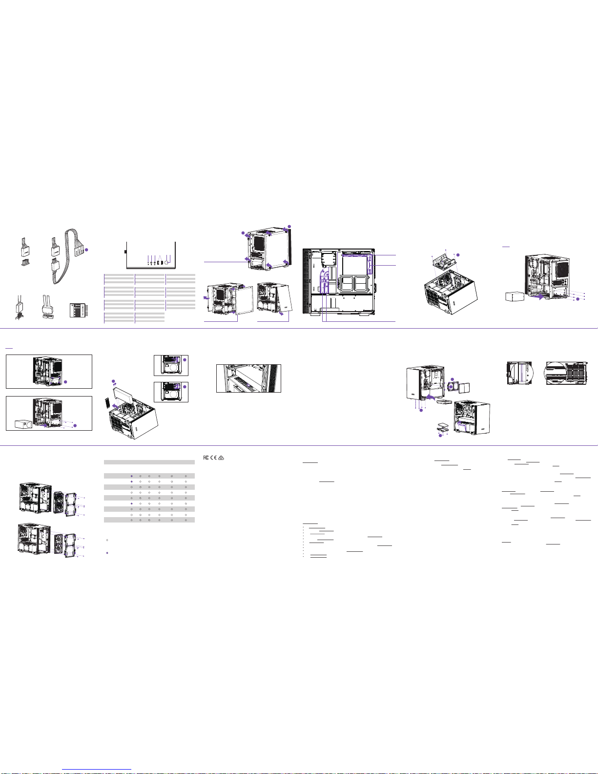
FAN AND RADIATOR SUPPORT
1.
2.
3.
4.
5.
6.
Power switch
Power LED
USB 3.1 Gen 1
HD Audio Output
Microphone Input
HDD LED
1.
2.
3.
4.
5.
6.
Interruptor de encendido
LED de alimentación
USB 3.1 Gen 1
Salida de audio HD
Entrada de micrófono
LED de unidad de disco duro
1.
2.
3.
4.
5.
6.
Interrupteur marche/arrêt
Témoin d’alimentation
USB 3.1 Gen 1
Sortie audio HD
Entrée micro
Témoin disque dur
1.
2.
3.
4.
5.
6.
Netzschalter
Betriebs-LED
USB 3.1 Gen 1
HD-Audioausgang
Mikrofoneingang
Festplatten-LED
1.
2.
3.
4.
5.
6.
Interruttore d’alimentazione
LED alimentazione
USB 3.1 Gen 1
Uscita audio HD
Ingresso microfono
LED HDD
1.
2.
3.
4.
5.
6.
Interruptor de alimentação
LED de alimentação
USB 3.1 Gen 1
Saída de áudio HD
Entrada para microfone
LED do HDD
1.
2.
3.
4.
5.
6.
Выключатель питания
Индикатор питания
USB 3.1 Gen 1
Звуковой выход HD
Разъем для подключения микрофона
Индикатор жесткого диска
1.
2.
3.
4.
5.
6.
전원 스위치
전원 LED
USB 3.1 Gen 1
HD 오디오 출력
마이크 입력
HDD LED
1.
2.
3.
4.
5.
6.
電源スイッチ
パワーLED
USB 3.1 Gen 1
HDオーディオ
マイク
HDD LED
1.
2.
3.
4.
5.
6.
电源开关
电源LED
USB 3.1 Gen 1
高清音频输出
麦克风输入
HDD LED
1.
2.
3.
4.
5.
6.
電源開關
電源LED
USB 3.1 Gen 1
高清音頻輸出
麥克風輸入
HDD LED
124 365
TOP
1x 120mm
FRONT
2x 120mm
2x 140mm
REAR
1x 120mm
FRONT
2x 120mm
REAR
1x 120mm
1
REMOVE SCREWS
REMOVE SFX PSU BRACKET
INSTALL ATX PSU
3
REMOVE FRONT PANEL
2
REMOVE SIDE PANEL
CABLE MANAGEMENT SYSTEM
SISTEMA DE GESTIÓN DE CABLES
SYSTÈME DE CÂBLAGE
KABELMANAGEMENTSYSTEM
СИСТЕМА ПРОКЛАДКИ КАБЕЛЕЙ
SISTEMA DI GESTIONE DEI CAVI
SISTEMA DE GERENCIAMENTO DE CABOS
케이블 관리 시스템
ケーブルマネジメントシステム
理线管理系统
整線管理系統
24-PIN CABLE AND
SMART DEVICE CABLE CHANNEL
FAN CABLE CHANNEL
8-PIN
CABLE CHANNEL
INSTALACIÓN DE LA PLACA BASE
INSTALLATION DE LA CARTE MÈRE
INSTALLATION DER HAUPTPLATINE
УСТАНОВКА СИСТЕМНОЙ ПЛАТЫ
INSTALLAZIONE DELLA SCHEDA MADRE
INSTALAÇÃO DA PLACA PRINCIPAL
마더보드 설치
マザーボードの装着
主板安装
主機板安裝
MOTHERBOARD INSTALLATION
E
D
D
A
C
HAZLO TÚ MISMO: SOPORTE PARA REFRIGERADOR LÍQUIDO
SUPPORT DE REFROIDISSEMENT LIQUIDE À ASSEMBLER VOUS-MÊME
WASSERKÜHLUNG MARKE EIGENBAU
SUPPORTO PER DISSIPATORE A LIQUIDO FAIDATE
SUPORTE A REFRIGERAÇÃO LÍQUIDA DIY
ПОДДЕРЖКА САМОСТОЯТЕЛЬНОЙ СБОРКИ ЖИДКОСТНОЙ СИСТЕМЫ ОХЛАЖДЕНИЯ
DIY 수냉식 쿨러 지원
水冷クーラー支持部の DIY
DIY 液体冷却器支持
DIY 水冷支援
DIY LIQUID COOLER SUPPORT
The Cable Bar could support up to 150mm tall tube reservoir with M4 screws
The bottom Panel could support D5 or DDC pump mount with M4 screws
La barra para cables podría soportar un depósito de tubo de hasta 150mm de alto con tornillos M4
El panel inferior podría soportar el montaje de una bomba D5 o DDC con tornillos M4
La barre de gestion des câbles peut supporter un réservoir d'une hauteur maximale de 150mm avec des vis M4
Le panneau inférieur peut supporter un montage de pompe D5 ou DDC avec des vis M4
Die Kabelschiene bietet Platz für einen bis zu 150mm hohen Rohrbehälter mit M4-Schrauben
Die untere Abdeckung bietet Platz für eine D5- oder DDC-Pumpenhalterung mit M4-Schrauben
La barra dei cavi supporta un serbatoio tubolare alto fino a 150 mm con viti M4
Il pannello inferiore supporta il montaggio della pompa D5 o DDC con viti M4
A barra de limpeza pode suportar um reservatório de tubos alto de 150 mm com parafusos M4
O painel inferior pode suportar montagem de bomba D5 ou DDC com parafusos M4
На кабельную панель можно устанавливать трубчатый резервуар высотой до 150мм с помощью винтов M4
На нижнюю панель можно устанавливать насос D5 или DDC с помощью винтов M4
케이블 바는 M4 나사로 최대 150mm 높이의 튜브 물통을 지지할 수 있습니다.
하단 패널은 M4 나사로 D5 또는 DDC 펌프 마운트를 지지할 수 있습니다.
ケーブルバーで、M4 ネジで高さが最大 150mm のチューブ式水タンクを支える必要があります。
ボトムパネルには、M4 ネジで D5 または DDC ポンプを取り付ける必要があります。
线缆条可以用 M4 螺丝支撑高达 150 毫米的高管容器
底部面板可以用 M4 螺丝支持 D5 或 DDC 泵安装
纜線桿使用 M4 螺絲,可以支撐最高 150mm 的蓄水管
底部面板使用 M4 螺絲,可以支撐 D5 或 DDC 泵安裝座
INSTALAÇÃO DA PLACA DE EXPANSÃO
확장 카드 설치
拡張カードの装着
扩展卡安装
擴充卡安裝
INSTALACIÓN DE LA TARJETA DE EXPANSIÓN
INSTALLATION DE LA CARTE D’EXTENSION
INSTALLATION DER ERWEITERUNGSKARTE
УСТАНОВКА ПЛАТЫ РАСШИРЕНИЯ
INSTALLAZIONE DELLA SCHEDA D'ESPANSIONE
EXPANSION CARD INSTALLATION
INSTALACIÓN DEL SOPORTE DE LA GPU
INSTALLATION DU SUPPORT DU GPU
INSTALLATION DES GPU-STÄNDERS
УСТАНОВКА ПОДСТАВКИ ДЛЯ ГРАФИЧЕСКОГО ПРОЦЕССОРА
INSTALLAZIONE SUPPORTO GPU
INSTALAÇÃO DO SUPORTE DA GPU
GPU 스탠드 설치
GPU スタンド取り付け
GPU 支架安装
GPU 座安裝
GPU STAND INSTALLATION
INSTALACIÓN DE DISCO DURO/SSD
INSTALLATION DU DISQUE DUR/SSD
HDD-/SSD-INSTALLATION
УСТАНОВКА ЖЕСТКОГО ДИСКА И SSDНАКОПИТЕЛЯ
INSTALLAZIONE HDD/SSD
INSTALAÇÃO DO HDD/SSD
HDD/SSD 설치
HDD/SSD 取り付け
HDD/SSD 安装
HDD/SSD 安裝
HDD/SSD INSTALLATION
UNSCREW THE INSERTS COVER
SCREW THE INSERTS COVER
B
B
B
F
C
E
F
1.
2.
3.
4.
5.
Plug the GPU onto the motherboard
Find a location where you can place the GPU stand and make sure the GPU stand would not interfere with the GPU fans
Remove the GPU and plug the GPU stand onto PSU shroud
Plug the GPU onto the motherboard again
Raise the GPU stand’s top cap until it slightly lifts the GPU
Conecta la GPU en la placa base
Busca una ubicación en la que puedas colocar el soporte de la GPU y asegúrate de que este no interfiera con los
ventiladores de la GPU
Extrae la GPU y conecta el soporte de la GPU en la envoltura PSU
Conecta la GPU en la placa base de nuevo
Levanta la tapa superior del soporte de la GPU hasta que suba levemente la GPU
Branchez le GPU sur la carte mère
Trouvez un endroit où placer le support du GPU en vous assurant qu'il ne gêne pas le fonctionnement des
ventilateurs du GPU
Retirez le GPU et branchez le support du GPU à la coque du bloc d'alimentation
Branchez à nouveau le GPU sur la carte mère
Soulevez le capot du support du GPU jusqu'à ce qu'il le soulève légèrement
1.
2.
3.
4.
5.
1.
2.
3.
4.
5.
1.
2.
3.
4.
5.
GPU an die Hauptplatine anschließen
GPU-Ständer so positionieren, dass keine Beeinträchtigung der GPU-Lüfter vorliegt
GPU entfernen und GPU-Ständer an Netzteilverkleidung anbringen
GPU erneut an die Hauptplatine anschließen
GPU mit der Oberkappe des Ständers leicht anheben
1.
2.
3.
4.
5.
Collegare la GPU alla scheda madre
Trovare una posizione in cui si possa collocare il supporto GPU ed accertarsi che questo non interferisca con le
ventole della GPU
Rimuovere la GPU e collegare il relativo supporto allo strato PSU
Ricollegare la GPU alla scheda madre
Sollevare la protezione superiore del supporto GPU in modo che sollevi leggermente la GPU
1.
2.
3.
4.
5.
Conecte a GPU na placa-mãe
Encontre um local no qual você pode colocar o suporte da GPU e certifique-se de que o suporte da GPU não interfere
nas ventoinhas da GPU
Remova a GPU e conecte o suporte da GPU no compartimento do PSU
Conecte a GPU na placa-mãe novamente
Levante a tampa superior do suporte da GPU até levantar a GPU levemente
1.
2.
3.
4.
5.
Установите графический процессор на материнскую плату
Найдите место, куда можно установить подставку для графического процессора, и убедитесь, что она не будет
мешать работе вентиляторов графического процессора
Извлеките графический процессор и установите подставку на кожух блока питания
Повторно установите графический процессор на материнскую плату
Поднимите регулятор высоты подставки, чтобы она слегка приподнимала графический процессор
1.
2.
3.
4.
5.
GPU를 마더보드에 꽂습니다.
GPU 스탠드를 배치할 수 있는 위치를 찾고 GPU 스탠드와 GPU 팬이 서로 닿지 않도록 주의합니다.
GPU를 제거하고 GPU 스탠드를 PSU 덮개에 꽂습니다.
GPU를 마더보드에 다시 꽂습니다.
GPU 스탠드가 GPU를 살짝 들 때까지 GPU 스탠드의 상단 캡을 올립니다.
1.
2.
3.
4.
5.
1.
2.
3.
4.
5.
1.
2.
3.
4.
5.
將 GPU 插入主機板
找到要安裝 GPU 座的位置,確定 GPU 座不會干擾 GPU 風扇
拆下 GPU 並把 GPU 座插到電源供應器遮罩上
將 GPU 插回主機板
抬升 GPU 底座的頂蓋,直到頂蓋能稍微把 GPU 推起
将 GPU 插入主板
找到可以放置 GPU 支架的位置,并确保 GPU 支架不会干扰 GPU 风扇
移开 GPU 并将 GPU 支架插入 PSU 罩盖
再次将 GPU 插入主板
提高 GPU 支架顶盖,直到略微提升起 GPU
GPU をマザーボードに差し込みます。
GPU ファンの動作に干渉しないように GPU スタンドを配置できる場所を決めます。
GPU を取り外し、GPU スタンドを PSU シュラウドに差し込みます。
もう一度 GPU をマザーボードに差し込みます。
GPU スタンド最上部のキャップを引き上げて、GPU を少し持ち上げます。
ATX PSU INSTALLATION
D
INSTALACIÓN DE LA FUENTE DE ALIMENTACIÓN
INSTALLATION DE L’ALIMENTATION
INSTALLATION DER STROMVERSORGUNG
УСТАНОВКА ИСТОЧНИКА ПИТАНИЯ
INSTALLAZIONE DELL’ALIMENTATORE
INSTALAÇÃO DA FONTE DE ALIMENTAÇÃO
전원공급장치 설치
電源の装着
电源安装
電源安裝
POWER SUPPLY INSTALLATION
SFX PSU INSTALLATION
USB 3.1 GEN 1 HD AUDIOUSB 2.0
IMPORTANT!
Install the PSU with the fan facing down.
CABLE CONNECTIONS
FOR NON-INTEL STANDARD F_PANEL HEADER USEFOR INTEL STANDARD F_PANEL HEADER USE
L
 Loading...