

Page 1

ALBERTA GAMING AND
LIQUOR COMMISSION
VIDEO LOTTERY TERMINAL
Service Manual & User Guide
A-016304-02
WMS GAMING, INC.
800 SOUTH NORTHPORT BOULEVARD
WAUKEGAN, ILLINOIS 60085
24-SERVICE: 866.WMS.4HLP (866.967.4457)
Page 2
AUGUST 2005
A
BOUT
G
ENERAL
Copyright Copyright © 2005, WMS Gaming Incorporated. All rights reserved. No part of this
documentation may be reproduced in any form or by any means or used to make
any derivative work (such as translation, transformation, or adaptation) without
written permission from WMS Gaming Incorporated.
WMS Gaming Incorporated reserves the right to revise this documentation and to
make changes in content from time to time without obligation on the part of WMS
Gaming Incorporated to provide notification of such revision or change.
WMS Gaming Incorporated provides this documentation without warranty of any
kind, either implied or expressed, including, but not limited to, the implied
warranties of merchantability and fitness for a particular purpose. WMS Gaming
may make improvements or changes in the product(s) and/or the program(s)
described in this documentation at any time.
T
HIS
I
NFORMATION
G
UIDE
16-010000-00
Unless otherwise indicated, WMS Gaming registered trademarks are registered in
the United States and may or may not be registered in other countries.
Other brand and product names may be registered trademarks or trademarks of
their respective holders.
Customer Service WMS Gaming is ready to help twenty-four hours a day. Contact our service number
at 800-378-7741.
Conventions For clarity, this Service Manual uses the following conventions:
Items that appear on a Screen Display (video screen) are identified in bold text.
Button names are shown in ALL CAPS text.
Individual parts, like the Printer, are capitalized.
Page 3
b
Shock and ESD Prevention
Tabl e 1 lists notice icons used in this guide.
Tab le 1 Notice Icon Descriptions
Icon Notice Type Description
Information Note Information about important features or instructions.
Shock and ESD
Prevention
Caution Information to alert you to potential damage to a program,
Warning Information to alert you to potential personal injury or fatality.
ESD Information to alert you to take proper grounding precautions
system, or device.
May also alert you to potential electrical hazard.
against electrostatic discharge (ESD) before handling a
product.
Begin any service procedure by completing the following steps to prevent electrical
shock and/or electrostatic discharge (ESD):
1 Unlock and open the Main Door.
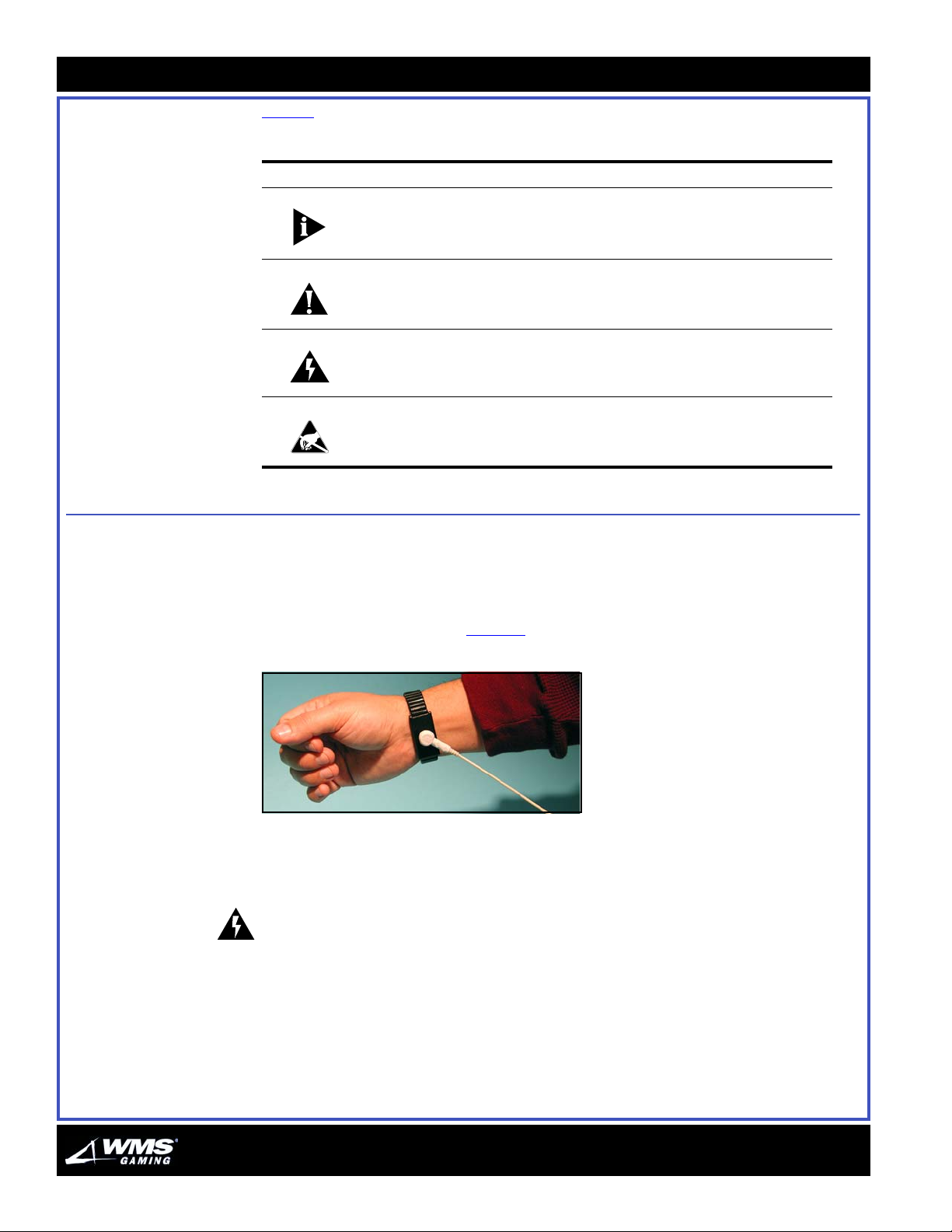
2 Fasten a resistive type (1 or 10 Meg) ESD wrist strap on arm and ensure that it
makes good skin contact, Figure 1
Figure 1 ESD Wrist Strap on arm.
.
3 Secure the clip end of the wrist strap to a ground braid on a game.
4 Power the game Off at the power switch.
5 If a Hopper is installed, remove it to access the Power Entry Assembly.
WARNING: Disconnecting the game Power Supply Cord is the only means of
disconnecting the game from power.
AUGUST 2005
Page 4
About This Guide: General Information
c
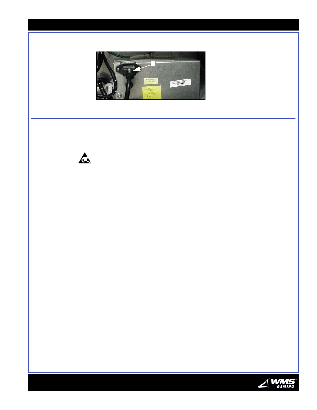
6 Disconnect the power supply cord from the Power Entry Assembly, Figure 2 (A).
Figure 2 Power Supply Cord plugged into Power Entry Assembly.
A
Special Handling Instructions for PCBs
Whenever accessing any printed circuit boards (PCBs) or components in direct
contact with PCBs, including EPROMs, CompactFlash® Cards, and PCB
connectors, use the following procedure to prevent ESD damage to sensitive
components.
Opening the game and unplugging the Power Supply Cord defeats the grounding
system on the game, as the grounding pin on the Power Supply Cord ultimately
connects the game to ground.
1 Verify that the game power switch is set to Off.
2 Verify that the ESD wrist strap is firmly secured to a game ground braid.
3 Reconnect the Power Supply Cord to the Power Entry Assembly.
4 Complete all necessary PCB or component handling steps.
5 If additional steps are required for this procedure, ensure the game power switch
is still set to Off, and disconnect the game Power Supply Cord before proceeding.
16-010000-00
Page 5
d
Special Handling Instructions for PCBs
Completing the Procedure
Complete the following steps to finish this procedure:
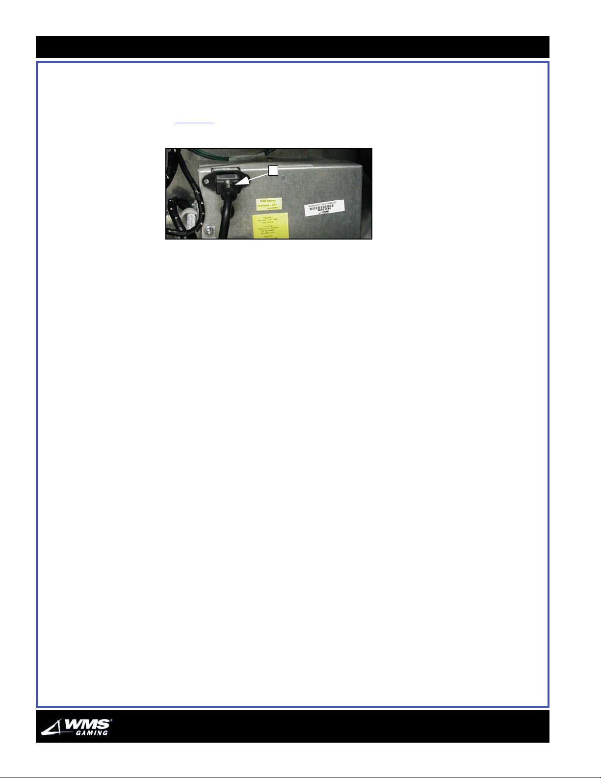
1 Reconnect the game Power Supply Cord to the Power Entry Assembly,
Figure 3
Figure 3 Power Supply Cord plugged into Power Entry Assembly.
(A).
A
2 Power the game On at the power switch.
3 Unclip the ESD wrist strap from the game.
4 Close and lock the Main Door (BBU).
5 Store the ESD wrist strap in a cool and dry location.
End of Procedure
AUGUST 2005
Page 6

AUGUST 2005
C
N
HAPTER
EW
G
AME
S
1
ETUP
16-015712-00
Table of Contents OVERVIEW ........................................................................................................................................ 1-2
Electrical Requirements ...............................................................................................................1-2
Precautions ...................................................................................................................................1-2
SAFETY............................................................................................................................................. 1-3
LEGAL REQUIREMENTS....................................................................................................................... 1-7
GAME DIMENSIONS ........................................................................................................................... 1-8
CPU-NXT BOARD IDENTIFICATION....................................................................................................1-10
SETTING UP THE GAME .................................................................................................................... 1-12
SETTING UP COMPONENTS.............................................................................................................. 1-14
MAKING FINAL ADMINISTRATIVE ADJUSTMENTS ..................................................................................1-16
Environmental Specifications ......................................................................................................1-3
Radio Frequency Interference .....................................................................................................1-3
PDU and General Power ...............................................................................................................1-4
Monitor ..........................................................................................................................................1-6
Canadian Interference Notice......................................................................................................1-7
Check for the Nameplate .............................................................................................................1-7
Laws that Protect Your Gaming Device .......................................................................................1-7
Reproduction and Transmittal Laws............................................................................................1-7
Local Laws.....................................................................................................................................1-7
Template Used to Mount Cabinet to Pedestal Base...................................................................1-8
AGLC Cabinet Measurements ......................................................................................................1-9
Front............................................................................................................................................ 1-10
Back ............................................................................................................................................ 1-11
Tools Required for Setup........................................................................................................... 1-12
Inspection................................................................................................................................... 1-12
Checking Components for Damage.......................................................................................... 1-12
Mounting the Game to the Base............................................................................................... 1-12
Providing Power to the Game.................................................................................................... 1-13
Setting Up the Bill Validator ...................................................................................................... 1-14
Setting Up the Monitor .............................................................................................................. 1-15
Games with a Host System ....................................................................................................... 1-15
Page 7
1-2
Overview
Overview This chapter provides an overview of the new game.
Electrical
Requirements
This section provides the electrical requirements necessary to set up the game.
Power requirements
Tabl e 1-1 displays the power requirements.
Table 1-1 Power Requirements.
Voltage
120 or 240 VAC 50 or 60 Hz
Line Frequency
2.75 amps. max at 220-240 VAC
Current
4 amps. max at 120 VAC
WARNING: Plugging your game into an improper line voltage source creates fire and
electrical shock hazards. An improper line voltage or frequency can also cause
damage or malfunctions.
Maximum cord and plug load
Table 1 -2 displays, in amps, the maximum cord and plug connected load to
receptacle.
Table 1-2 Maximum Cord and Plug Connected Load
to Receptacle (in amps).
Circuit Receptacle Maximum Load
15 or 20 15 12
20 20 16
30 30 24
Be sure and locate the socket outlet close to the installed position of this game so
that the outlet is easily accessible.
CAUTION: To avoid overloading branch circuits that have two or more receptacles or
outlets, the combined cord and plug-connected load should not exceed the
Maximum Load.
Precautions This section provides required precautions for setting up the new game.
CAUTION: This device has more than one power supply cord. Disconnect two power
supply cords before servicing to avoid electric shock.
16-015712-00
Page 8
Chapter 1: New Game Setup
1-3
WARNING:
The socket outlet is the means of disconnection and shall be installed near the
equipment and shall be easily accessible.
Avoid electrical shocks! The optional player tracking system must be a CSA/
NRTL/C or CSA/US/C listed type which plugs into a wall receptacle or the
service receptacle of the PDU. Alternately, an unapproved player tracking
system may operate from a CSA/NRTL/C or CSA/US/C listed AC adapter. Use
the precautions in Table 1 -3
Tab le 1- 3 Safety precautions.
Issue Solution
Holes in game To protect cables, grommet player tracking system mounting holes in the
External player tracking system player tracking system mounting holes in the game must not allow access
Power player tracking system power consumption must not exceed the rating of
player tracking system Mounted
Inside the game
as a guide.
game
to live parts
the receptacle
A line voltage-powered player tracking system must have a separate
enclosure
NOTICE: The game should come with a 2.4 in. toroid (5556-005782-00) that is
attached to the line cord by looping the cord three times through the hole in the
toroid at the PDU plug end.
Environmental
Table 1-4 shows the environmental specifications required to operate the game.
Specifications
Tab le 1- 4 Environmental Specifications.
Maximum Relative Humidity Operating Room Temperature Range
95% 32
o
F (0o C) - 95o F (35o C)
Safety This section provides the information you need to operate the game safely.
Radio Frequency
Interference
FCC Interference Notice
This equipment has been tested and complies with the limits for a Class B digital
device, pursuant to Part 15 of the FCC Rules. These limits provide reasonable
protection against harmful interference when the equipment is operated in a
commercial environment.
16-015712-00
Page 9
1-4
Safety
WARNING: This equipment generates, uses, and may radiate radio frequency
energy. If not installed and used according to the instruction manual, this
equipment may cause harmful interference to radio communications. Operation of
this equipment in a residential area is likely to cause harmful interference.
Interference must be corrected at the expense of the user.
PDU and General
Power
Follow the steps below to ensure electrical safety:
Ensure that device is properly grounded.
To avoid electrical shocks, do not plug in the game until you inspect and properly
ground it.
Only connect your game to grounded, three-wire outlets.
Do not use a cheater plug to defeat the ground pin of the power cord. Do not cut
off the ground pin.
After servicing a game, ensure that ground wires are secure; only then should
you close and lock the gaming device.
If the power supply cord is damaged, it must be replaced by the manufacturer, a
service agent, or a similarly qualified person in order to avoid a hazard.
Please note that this gaming device is not suitable for outdoor use.
Disconnect power supply before servicing
When performing any maintenance or modification to the gaming device, ensure
the power supply cord is disconnected from the outlet. Unplugging all power supply
cords is the only means of disconnecting the game. Always verify that power is off in
the component you are accessing for maintenance or repair.
Use only the specified replacement fuse
To avoid electrical shock, use the replacement fuse indicated on the specification
sticker. The replacement must match the original fuse type, voltage rating, and
current rating.
16-015712-00
Page 10
Chapter 1: New Game Setup
1-5
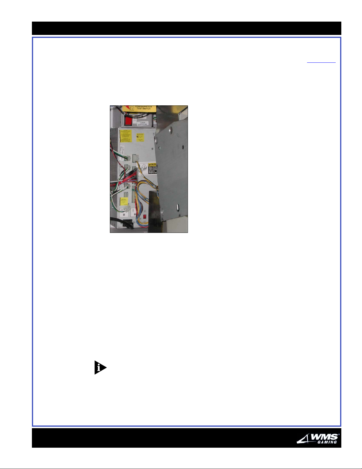
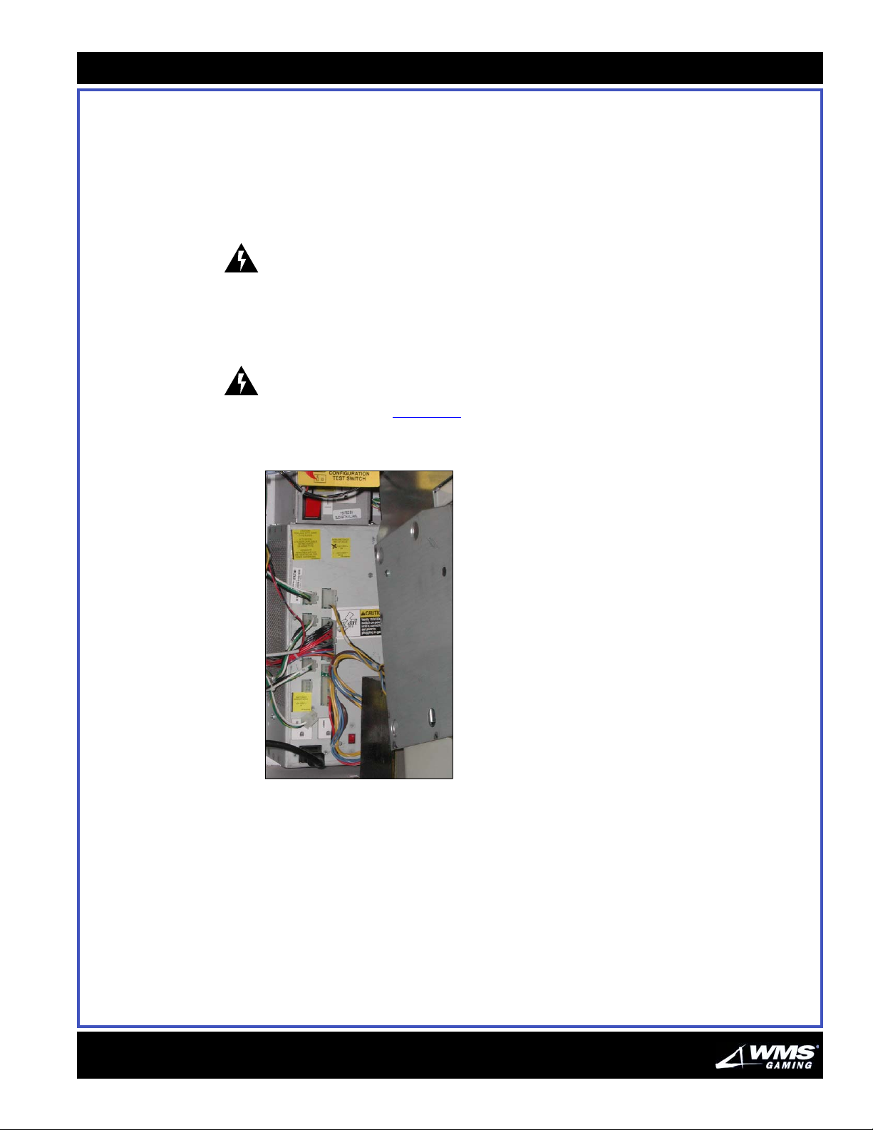
The power distribution unit
The power distribution unit (PDU) supplies power to many game components and
accessories. The PDU is located on the lower right inside cabinet wall, Figure 1-1
The PDU has a Main Switch for turning the game On or to STANDBY mode. In
STANDBY mode, the switched outlet(s) and many game components are turned off,
while the unswitched outlet(s) located on the PDU remains powered.
Figure 1-1 Power Distribution Unit.
.
The front of the PDU has the following features:
The Main Switch:
pressing the top of the switch turns the power On
pressing the bottom places the game in STANDBY mode
The Fuse, warning sticker, and specification sticker
The Unswitched Service Receptacle with the line voltage sticker
Checking the line voltage sticker
Your gaming device has a built-in service receptacle. This receptacle provides AC
line voltage power. For safety, a line voltage sticker must identify the receptacle. A
mark on the sticker must specify the intended line voltage (120 or 240 VAC).
Operating equipment using the wrong voltage may cause lethal shocks, serious
burns and equipment damage.
NOTICE: If your game does not include a properly marked sticker, contact WMS
Gaming immediately.
16-015712-00
Page 11
1-6
Safety
Monitor This section provides safety information on the game monitor.
Removing the Monitor
WARNING: Never remove the Monitor with game power switched On. Otherwise,
damage may occur to the logic and touch screen boards.
Removing liquids
WARNING: Remove any liquids in the drain tube and gutter before removing the
monitor from the cabinet. Failure to dry these areas could damage components!
Before replacing the monitor, check that the V-channel gutter, nozzle, and drain
tube are clear. Reposition the drain tube so that if liquids are spilled on the monitor,
the liquid drains safely away from electronic components.
Handling CRTs and fluorescent tubes with care
Video machines include monitors with fragile cathode ray tubes (CRTs), and most
games contain fluorescent lamp tubes. Fluorescent tubes and CRTs are evacuated
glass containers. The vacuum exerts considerable stress on the glass. Because of
this stress, if you drop a fluorescent tube or CRT, it may implode. Shattered glass
can fly eight feet or more from the implosion. Use extreme caution when handling a
monitor. Determine where you will place the monitor before removing it.
Servicing Monitors
Only qualified service technicians should turn power On when the monitor is out of
the cabinet.
Repairing Monitors
High voltages may exist within the monitor circuitry and CRT even after you
disconnect power.
WARNING: When removing or repairing a monitor, take care to avoid electrical
shock. Do not touch internal parts of the monitor with your hands or metal objects.
16-015712-00
Page 12

Chapter 1: New Game Setup
1-7
Legal Requirements
Canadian Interference
Notice
Check for the
Nameplate
Laws that Protect Your
Gaming Device
Reproduction and
Transmittal Law s
This section provides the legal requirements for the game.
This Class B digital apparatus meets all requirements of the Canadian InterferenceCausing Equipment Regulations.
When WMS ships a game, it complies with international EMC and safety
regulations. The nameplate is proof. If the nameplate is missing or damaged, you
may become subject to legal action. If your game does not include the proper
nameplate, call WMS immediately.
International copyright, trademark and patent laws protect your game.
Unauthorized modifications may be illegal under international law. This principle
also applies to WMS logos, designs, publications and assemblies. Facsimiles of
WMS equipment (or any feature of it) may be illegal. This principle applies to
facsimiles manufactured with or without WMS Gaming Inc. components.
Reproduction or transmittal of this publication or any other WMS Gaming
publication is only permitted by a purchaser of WMS Gaming products, for the
express purpose of maintaining and servicing those WMS Gaming products
purchased. Except as provided above, these WMS Gaming publications may not be
reproduced by mechanical, photographic or electronic means, for any other
purpose or use without prior written permission of the publisher.
Local Laws Operation of gaming devices may be subject to local laws and regulations. This
manual does not solicit sale of gaming devices where you may not lawfully operate
them.
16-015712-00
Page 13
1-8
Game Dimensions
Game Dimensions This section provides the dimensions for the game.
Template Used to
Mount Cabinet to
Pedestal Base
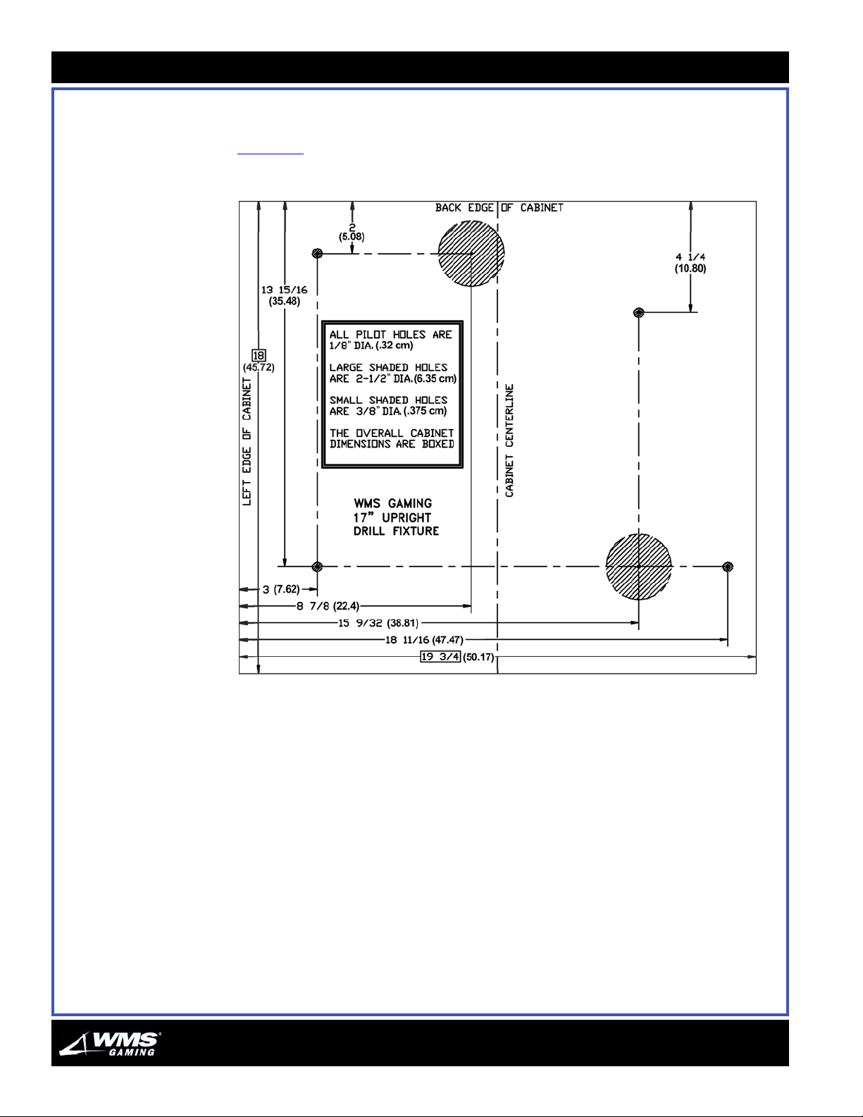
Figure 1-2 provides the template for mounting the game to the pedestal base.
Figure 1-2 Template for mounting cabinet to pedestal base.
16-015712-00
Page 14
Chapter 1: New Game Setup
1-9
AGLC Cabinet
Measurements
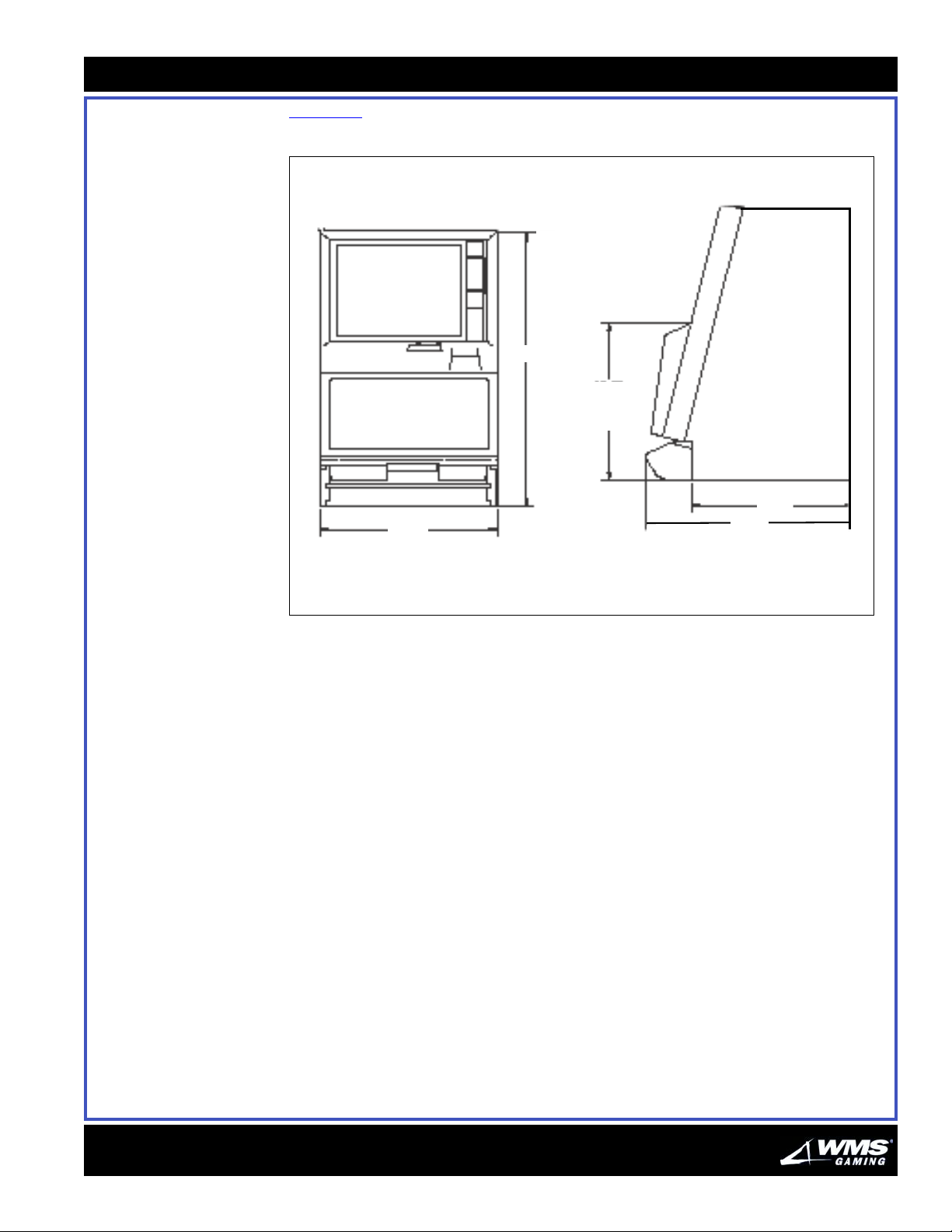
Figure 1-3 provides dimensions in inches for the AGLC cabinet.
Figure 1-3 AGLC cabinet dimensions in inches.
30.44
17.47
BUTTON
PANEL
HEIGHT
19.75
18.00
23.02
16-015712-00
Page 15
1-10
CPU-NXT Board Identification
CPU-NXT Board
Identification
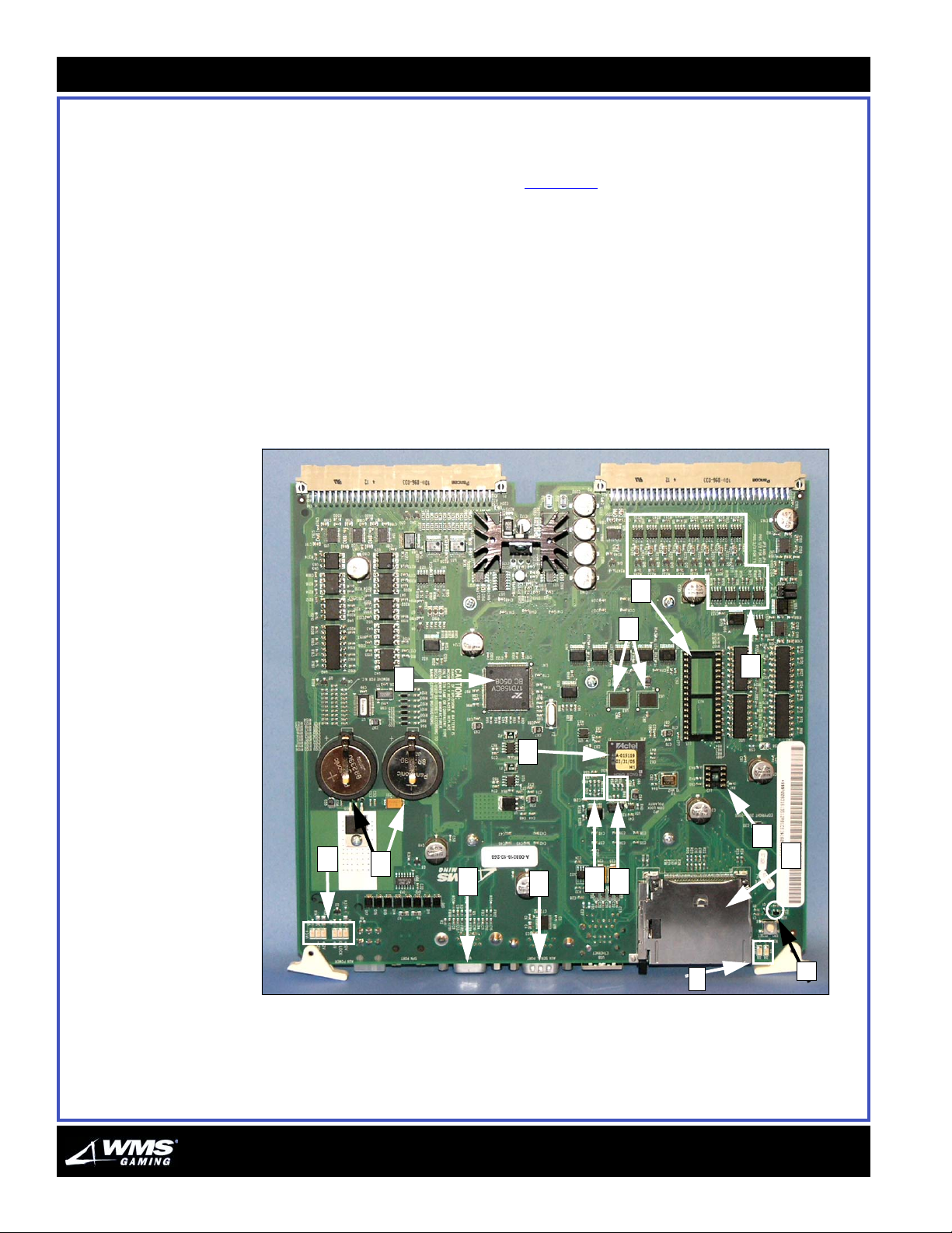
This section provides details on the CPU-NXT Board components.
Front Identify the following components in Figure 1-4:
A - Auxiliary serial port
B - Jurisdictional EEPROM
C - LEDs (6)
D - Batteries (2) for SRAM
subsystem
E - CompactFlash drive (Game)
F - Boot EPROM (8 Mbit)
G - Custom Logic Device (FPGA)
H - Video port
Figure 1-4 Firefighter II (A-008316-13-256) - front view.
I - Lamp/LED matrix drivers
J - Voltage monitor/reset
K - OCTAL UART serial ports
L - Platform ID (soldered jumpers)
M - Board ID (soldered jumpers)
N - Battery-backed SRAM
O - CompactFlash drive activity
(Top Box)
LEDs
F
N
I
K
G
B
C
D
M
H
A
L
O
E
J
16-015712-00
Page 16
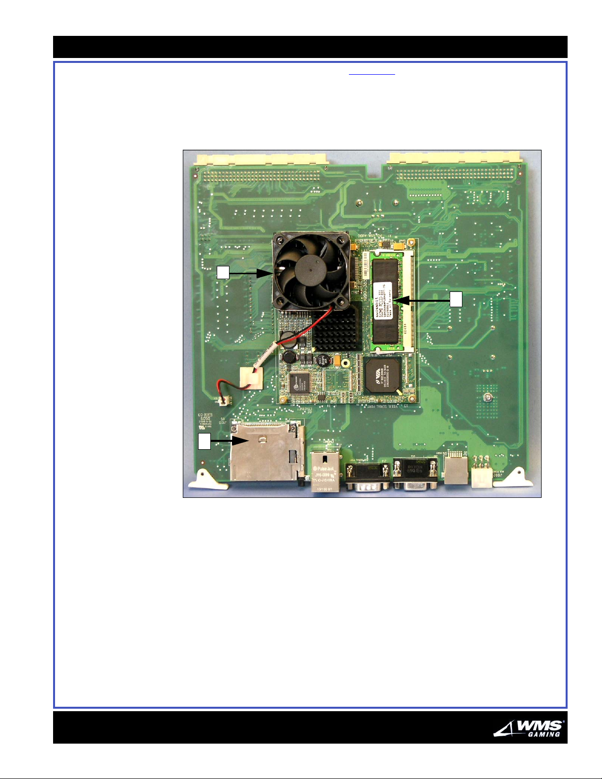
Back Identify the following components in Figure 1-5:
P - Intel Pentium III CPU (under fan)
Q - RAM
R - CompactFlash drive (OS)
Figure 1-5 Firefighter II (A-008316-13-256) - back view.
P
Chapter 1: New Game Setup
Q
1-11
16-015712-00
R
Page 17
1-12
Setting Up the Game
Setting Up the
Game
Tools Required for
Inspection Follow the steps below to make certain your game was not damaged during
Setup
This section provides the procedures required to set up the game.
Listed below are the tools required to set up the game:
Electrical Outlet Tester
Voltmeter
11/32" Nut Driver
#2 Phillips Screwdriver
7/16" Nut Driver
7/8" Wrench
shipping.
1 Open the shipping container.
2 Inspect the cabinet exterior for damage.
3 Determine the following:
If you... then...
find damage file a claim with your carrier
do NOT find damage remove and set aside everything from the shipping container
Checking Components
for Damage
Mounting the Game to
the Base
Check the components listed below for damage or improper mounting:
Cash Box
Coin Validator
Bill Validator
Marquee Lamp and Glass
Monitor
Power Supply
Printer
Speaker
Follow the steps below to mount the game to the base. Refer to the template
drawing in Figure 1-2
as you proceed.
1 Use the Plexiglas template (31-003296) to line up mounting holes on the
pedestal base.
2 Drill all holes as indicated on the template.
3 Use the mounting hardware enclosed in the game to mount the cabinet to the
base.
16-015712-00
Page 18
Chapter 1: New Game Setup
1-13
Providing Power to the
Game
Perform the steps below to provide power to the game.
1 Use a voltmeter to measure your line voltage at the outlet. Verify that the line
voltage is either 120 or 220 VAC, depending on the nominal value for your
jurisdiction. A switch on the connector side of the PDU selects the line voltage
range. The range options are 100 to 120 volts, and 220 to 240 volts. The game
accepts a line frequency of 50 to 60 Hz.
WARNING: Plugging your game into an improper line voltage source creates fire
and electrical shock hazards. An improper line voltage or frequency can also
cause game damage or malfunctions.
2 Use an outlet tester to check for properly implemented ground, hot and neutral
outlet wiring.
WARNING: Use only a grounded AC outlet.
3 Locate the PDU, Figure 1-6
. You'll find the PDU on the lower right inside cabinet
wall.
Figure 1-6 Power Distribution Unit.
16-015712-00
4 Switch game power at the PDU to STANDBY.
5 Route the AC power cord through the right, left or back floor channel under the
cabinet.
6 Plug the receptacle end of the line cord into the PDU.
7 Plug in the game.
Page 19
1-14
Setting Up Components
8 Switch game power On at the PDU. During a normal startup, the following events
should occur:
a The monitor and lamps come on.
b The bill acceptor undergoes a self test.
9 Switch off game power at the PDU.
Setting Up
This section describes how to set up components in the game.
Components
Setting Up the WBA Perform the procedure in this section to set up the JCM World Bill Acceptor
(WBA).
1 Access the WBA by unlocking the belly glass door (key switch on right side of the
player panel).
2 Pull out the belly glass door release.
3 Lower the belly glass door and locate the WBA on the right-front side of the
cabinet.
4 Unlock the WBA.
5 Check inside the WBA and determine the following:
If a Cash Box is... then...
present 1 remove the Cash Box by depressing the thumb release latch on the
right side of the WBA.
2 pull the Cash Box up and out by the handle.
3 replace the Cash Box by sliding it back into the acceptor until it is
latched in place.
4 proceed to step 6
.
®
NOT present 1 insert the Cash Box.
2 slide the Cash Box into the acceptor until it is latched in place.
3 go to step 6
.
6 Close and lock the WBA door and belly glass door.
16-015712-00
Page 20
Chapter 1: New Game Setup
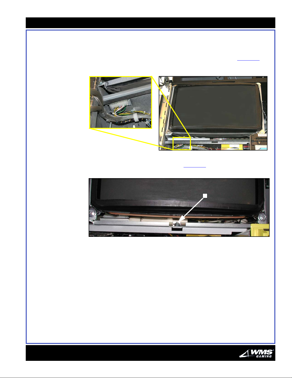
Setting Up the Monitor This section describes how to set up the monitor.
Ensure that the Molex
®
mini-fit connector is properly connected to the monitor as
follows:
The connector is beneath the monitor in the left front corner, Figure 1-7.
Figure 1-7 Molex mini-fit connector.
The monitor is mounted to the shelf by a 7/16" flange grip nut located under
the monitor shelf at the front center, Figure 1-8
Figure 1-8 Flange grip nut.
1-15
(A).
Games with a Host
System
A
On games with a host system, communication cables must be connected to the
backplane. Connect host communication cables according to recommendations
of the communications system provider.
16-015712-00
Page 21

1-16
Making Final Administrative Adjustments
Making Final
Administrative
Adjustments
Perform the following steps to finish setting up the new game.
1 At the PDU, switch game power On.
2 Adjust the game play sound volume. Refer to the Software Administration chapter
for details.
3 Close and lock the Logic Door and Cash Box Door.
4 Enter Administration Mode to select the machine protocol address, if necessary.
Refer to the Software Administration chapter for details.
5 Run a diagnostic check of the software and hardware. Refer to the Software
Administration chapter for details.
6 Verify that the Logic Door is closed and locked.
7 Record starting cumulative totals by copying them off the mechanical meters next
to the monitor.
8 Close and lock the Main Door.
16-015712-00
Page 22

AUGUST 2005
C
HAPTER
T
ROUBLESHOOTING
2
16-015713-00
Table of Contents OVERVIEW ........................................................................................................................................ 2-2
The Key Switch..............................................................................................................................2-2
ERROR CODES AND TILT CODES.......................................................................................................... 2-3
BILL VALIDATOR AND COIN MECHANISM TILT GUIDE.............................................................................. 2-6
BUTTON & SWITCH TILTS ................................................................................................................... 2-7
COMMUNICATION GUIDE..................................................................................................................... 2-7
DOOR TILT GUIDE.............................................................................................................................. 2-8
HARD METER TILT GUIDE................................................................................................................... 2-8
MONITOR GUIDE ............................................................................................................................... 2-9
POWER GUIDE................................................................................................................................. 2-10
PRINTER TILT GUIDE ........................................................................................................................ 2-10
STATIC RAM TILT GUIDE.................................................................................................................. 2-11
TOUCH SCREEN TILT GUIDE ..............................................................................................................2-13
The Attendant Key.........................................................................................................................2-2
Candle Codes ................................................................................................................................2-3
Tilt Codes .......................................................................................................................................2-3
Page 23
2-2
Overview
Overview This section describes the various error codes and operational issues you may
encounter while working with the terminal. The resolution for many of the errors
relies on the Key Switch and the Attendant Key.
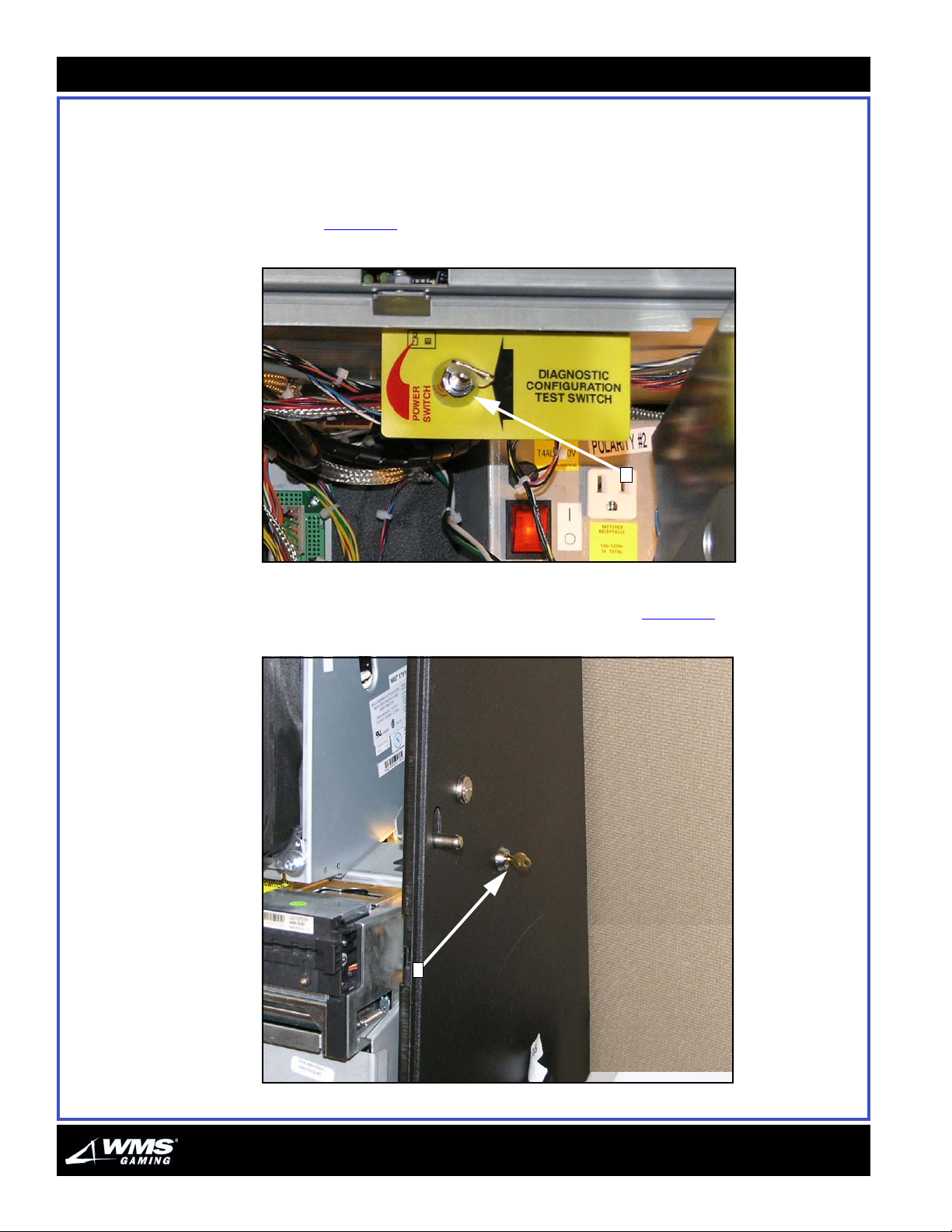
The Key Switch The Key Switch is on the right side of the metal bar spanning the middle of the
cabinet, Figure 2-1
Figure 2-1 Key Switch.
(A).
A
The Attendant Key The Attendant Key is on the right side of the cabinet, Figure 2-2 (A).
Figure 2-2 Attendant Key.
A
16-015713-00
Page 24
Chapter 2: Troubleshooting
2-3
Error Codes and Tilt Codes
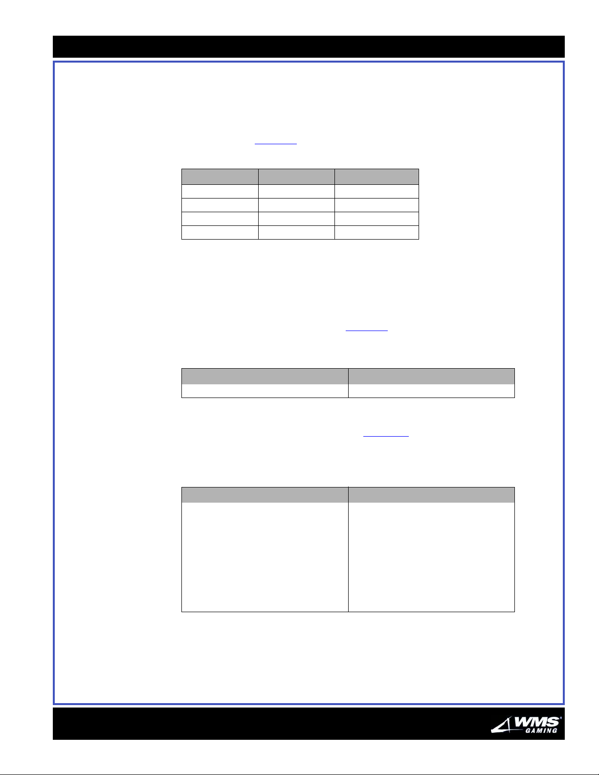
Candle Codes The two-stage candle indicates game status. The VLT employs both levels of the
Tilt Codes When the game enters Tilt Mode, a tilt code appears on the monitor. This section
The following are error or tilt code categories you may encounter on the VLT.
candle to convey information about its operation. Candle codes and their meanings
can be found in Table 2-1
Tab le 2- 1 Candle codes.
Event Top (Yellow) Bottom (Red)
Win $50 or Higher Slow Flash Slow Alternate Flash
Call Attendant On Off
Door Open Fast Flash Off
Tilt/Error Off On
.
describes the various types of tilt codes.
CPU EPROM Tilts
This game only has one EPROM tilt, Table 2-2. To clear the CPU EPROM tilt, replace
the board or the chip, then clear the RAM.
Tab le 2- 2 CPU-NXT EPROM Tilt Code.
Display Meaning
ROM Checksum Error Bad CPU-NXT Board EPROM
Bill Validator/Coin Acceptor Tilts
Bill Validator and Coin Acceptor tilts, Table 2- 3, involve problems with the Bill
Validator and coin comparator. To clear Bill Validator and Coin Mech tilts, turn the
Attendant KEY. Coin Mech "Long Coin" tilts self-clear after 25 seconds.
Tab le 2- 3 Bill Validator/Coin Mech Tilt Codes.
Display Meaning
Cash Box Missing No stacker in Bill Validator
Bill Validator Jam Bill stuck in Bill Validator
Bill Validator Comm Fault Bill Validator won’t talk with port
Coin Jam Coin jammed in machine
Reversed Coin Player reversed coin in chute
Bill Validator LEDs off Bill validator full or failure
Invalid Bill Bill Validator rejected bill
Long Coin Coin signal lasted too long
16-015713-00
Page 25
2-4
Error Codes and Tilt Codes
Door Access Tilts
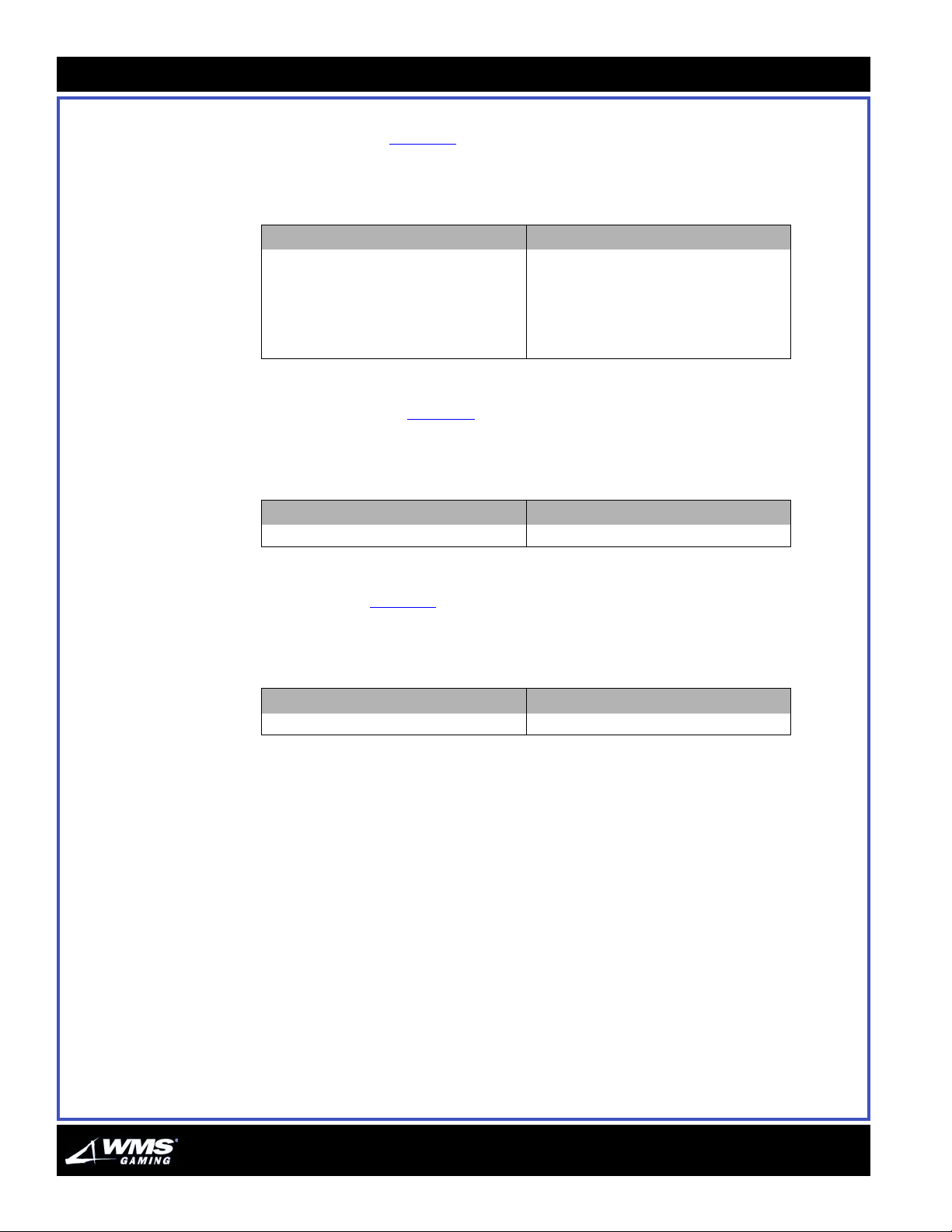
Door access tilts, Tabl e 2-4, provide information on the Main Door, Logic Door, Drop
Door and Bill Door. An open door or missing stacker produces a tilt. To clear door
access tilts, close the open door.
Table 2-4 Door Access Tilt Codes.
Display Meaning
Bill Door Open Open Bill Door
Drop Door Open Open Drop Door
Main Door Open Open Main Door Power Off
Bill Jam Service Door Open Open Top Bill Validator Door
Logic Door Open Open Logic Door
Hard Meter Tilt
The hard meter tilt, Table 2-5, indicates improper operation of hard meters on the
side of the game. These electromechanical meters report important game statistics
and may fail on occasion. To clear the hard meter tilt, turn the Attendant Key.
Table 2-5 Hard Meter Tilt Code.
Display Meaning
Mechanical Meter Failure Dead mechanical meter
Printer Tilt
The printer tilt, Table 2-6, communicates printer problems. For instance, a printer tilt
might occur if the printer runs out of paper. If printer-to-CPU communications fail,
you might also see a tilt message. To clear the printer tilt, power cycle the printer.
Table 2-6 Printer Tilt Code.
Display Meaning
Printer Error Malfunctioning printer
16-015713-00
Page 26
Chapter 2: Troubleshooting
2-5
Static RAM Tilts
Static RAM tilts, Tabl e 2-7, signal errors in data stored in the CMOS static RAM
chips. To clear static RAM tilts, clear the RAM.
Tab le 2- 7 Static RAM Tilt Codes.
Display Meaning
Battery Fail Dead battery
CRC Corrupt Op sys data corruption
Deck corrupt Bad deck of cards
Heap Corrupt Corrupt ‘heap’ memory
Heap Full Full ‘heap’ memory area
Memory Cleared The RAM is cleared
RAM Signature Corrupt Wrong RAM signature
Recoverable Auxiliary Main Meter Corruption Recoverable auxiliary main meter corruption
Recov Main Meter Corruption Recoverable main meter corruption
Unrecov Game Meter Corrupt Unrecoverable game meter corruption
Unrecov Main Meter Corruption Unrecoverable main meter corruption
Touch S creen Tilts
Touch Screen tilts, Table 2-8, occur when communications between the Touch
Screen Controller and I/O Board fail. Communications breakdowns may result from
bad cables, or from connectors or chips on circuit boards. Signals between the
Touch Screen and the I/O Board also pass through the Backplane Board. To clear
Touch Screen tilts, turn the Attendant Key.
Tab le 2- 8 Touch Screen Tilt Codes.
Display Meaning
No Touch Screen Response Bad touch screen cable or board
Touch Screen Coms Fault Bad cable, board or I/O input
16-015713-00
Page 27
2-6
g
Bill Validator and Coin Mechanism Tilt Guide
Bill Validator and
Coin Mechanism
Tilt Guide
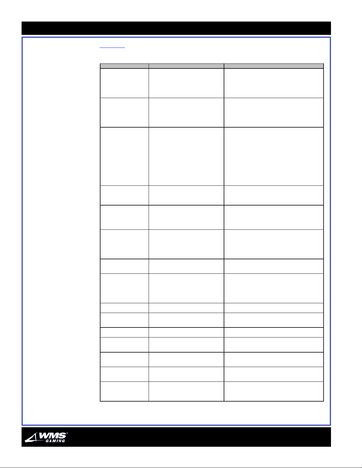
Tabl e 2-9 provides the Bill Validator and Coin Mechanism tilts and their solutions.
Table 2-9 Bill Validator and Coin Mechanism Tilts
Symptom Probable Cause Solutions
"Cash Box Missing"
appears on monitor
* "Bill Validator
Communication Fault"
appears on monitor screen
* External (green) Bill
Validator LEDs are out
* Bill Validator won't accept
currency
* "Invalid Bill" appears on
monitor screen
* "Bill Validator Jam"
appears on monitor screen
* External (green) Bill
Validator LEDs are out
Coins don't drop
"Coin Jam" appears on
monitor screen
* Coins jam comparator
* VGD doesn't give credits
Comparator won't accept
coins
"Long Coin" appears on
monitor
VGD doesn't give credits
"Reversed Coin" appears
on monitor
"Bill Validator Currency
Type/Denomination
Mismatch" Monitor Tilt
"Bill Validator Failure"
appears on monitor
"Bill Validator Cheated"
appears on monitor
"Bill Validator Cash Box
Full" appears on monitor
1. No Cash Box.
2. Bent Cash Box switch mounting
bracket.
3. Bad Cash Box cable. 3. Repair or replace cable.
4. Bad Cash Box switch. 4. Replace switch.
1. Faulty cable. 1. Check or replace Bill Validator data cable.
2. Bill Validator failure. 2. Replace Bill Validator. Check new Bill Validator by
1. Bad bill. 1. Try another bill.
2. Bad or disabled Bill Validator. 2a. Machine accepts coins: Does Bill Validator take bill
3. Loose Bill Validator power connections. 3. Check for 120 VAC at power cable, or for loose
4. Dust and dirt. 4. Clean Bill Validator with cleaning pad.
5. Wron
DIP switch settings. 5. Check DIP switch settings.
6. Bad data cable. 6. Repair or replace bad cable.
1. Full Bill Validator Cash Box 1. Collect Cash Box and replace with an empty one.
2. Jammed Bill Validator 2. Clear the jam and test the Bill Validator in
1. Coin jam in coin chute. 1. Find jam location by looking through coin chute slits.
2. Someone inserted coin that was too
large.
3. Mismounted coin mech. 3. Remount coin mech.
1. Coin jam. 1. Clear coin jam.
2. Dirty or faulty Opto Board. 2a. Can't clear tilt by cycling power? Opto Board may be
1. No sample coin in coin comparator's
sample coin retainer.
2. Bad comparator. 2. Replace comparator.
1. No power to comparator (LED is off). 1. Check power cable. If cable's open or shorted,
2. Bad sample coin. 2. Replace sample coin.
3. Maladjusted c omparator accept/reject
potentiometer.
4. Bad comparator. 4. Replace comparator.
Long coin (coin took too long between
detector optos).
1. Bad harness between comparator and
opto.
2. Bad Opto Board. 2. Repair or replace Opto Board.
Reversed coin. Player tried to remove a coin with string or similar
An incorrect Bill Validator or RAM clear is
installed.
Bill Validator has reported failure or error. 1. Verify problem: Perform typical currency test.
Bill Validator has been cheated (Bill
Validator did not award credits for bill).
Bill Validator Cash Box is full. 1. Check Cash Box switch, and switch harness .
1. Replace Cash Box in Bill Validator.
2. Bend back the bracket.
running the currency test.
in and then spit it out? Yes: Bill may put machine over
payout limit. No: Replace Bill Validator.
2b. Machine doesn't accept coins: Locked out machine,
open door or tilt. Clear tilts and shut door.
connections.
Administration Mode.
2. Carefully dislodge coin.
faulty. Use Input Test to check for proper switching.
Display should read "O" with no coins in chute.
2b. Opto Board fails test? Clean or replace board.
1. Insert nominal coin in sample coin retainer. Coin
should neither be worn nor brand new.
replace it.
3. Adjust accept/reject selectivity at comparator
potentiometer.
Player tried strung coin.
1. Replace comparator.
device.
Install correct Bill Validator or RAM clear. Repeat RAM
clear.
2. Reset Bill Validator by removing and replacing Cash
Box.
1. Check Bill Log. Perform typical bill test.
2. Reset Bill Validator by removing and replacing Cash
Box.
2. Empty Cash Box and place back in game.
3. Reset Bill Validator by removing and replacing Cash
Box.
16-015713-00
Page 28
Chapter 2: Troubleshooting
2-7
Button & Switch Tilts
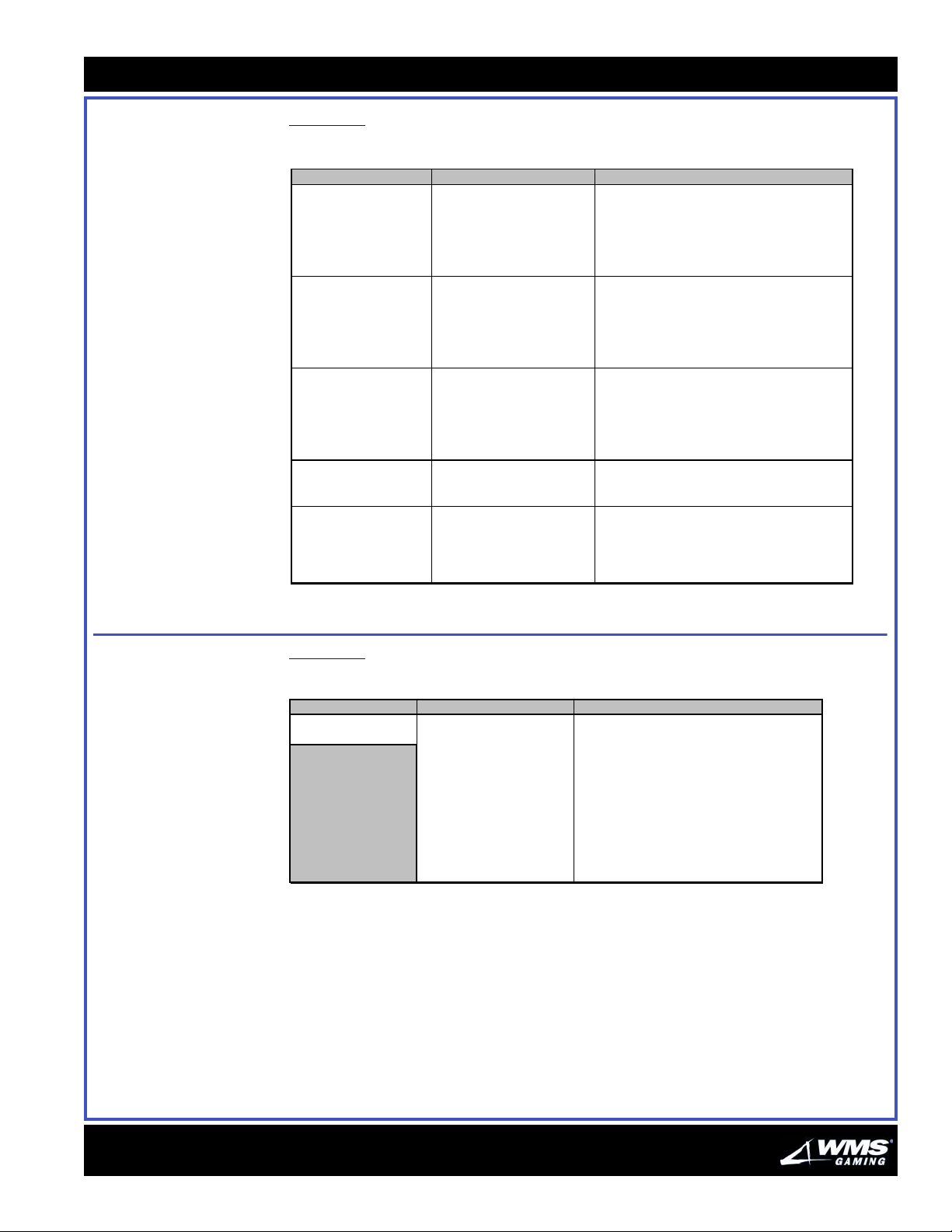
Table 2-10 features a troubleshooting guide for Button and Switch Tilts.
Tab le 2- 10 Button and Switch Tilt troubleshooting guide.
Symptom Probable Cause Solutions
Button: A Play er P anel
button does not operate.
Button and Swit c h:
Opening and closing any
door or turning the K ey
Switch fail s t o clear error
messages.
Button Lamp: A P l ayer
Panel but t on lam p does
not light
Switch: ADMINISTRATOR
KEY switch does not
operate.
Switch: Door switch does
not operate.
1. Loose cable c onnecti on at
top of back pl ane board.
2. Bad pl ayer panel wiring.
3. Bad switch. 3. Replace switch.
4. B a d switc h wiring. 4. Rewi r e switc h.
5. B ad F ast on® c onnect or. 5. Repl ace c onn ecto r at but ton.
1. Syst em hal t . 1. Turn power off and wait t hree s ec onds. Then
2. Loose connection at
switch.
1. Bad bul b. 1. Replace bul b.
2. Loose cable c onnecti on at
top of back pl ane board.
3. Bad pl ayer panel wiring. 3. Repair or replace pl ayer panel c able.
4. B ad F ast on® c onnect or. 4. Repl ace c onn ecto r at but ton.
5. B a d switc h wiring. 5. Rewi r e switc h.
1. Bad switch. 1. Replace switch.
2. Bad c abl e harnes s . 2. Repair or replace harnes s .
3. B ad F ast on® c onnect or. 3. Repl ace c onn ecto r at bac kplane.
1. Bad switch. 1. Replace switch.
2. Bad s wi t ch cabl e. 2. Repair or replace s wi t c h cable.
3. Bent , maladjusted or
mis s i ng ac tuator bracket.
4. Bad switch wiring.
1. P l ug cable i n sec urel y.
2. Repair or replace player panel cabl e.
turn power on.
2. Repair connection.
2. P l ug cable i n sec urel y.
3. St rai ght en, adj us t or replace brac k et.
4. Rewi r e switc h.
Communication Guide
Table 2-11 provides the communication tilts and their solutions.
Tab le 2- 11 Communication Tilts.
Symptom Probabl e Ca use S ol utions
No Communication 1. Bad power line t o s l ot
NOTICE
Report error codes t o
central communication
site for evaluat ion and
processing. Codes
enable use of advanc ed
diagnost ic facilties.
machine.
2. Host communications
jumpers not set properly .
3. B l own 4A SB, main P DU
fuse.
4. Bad communi cation
cables.
5. Bad external
comm unicati on power s upply.
6. Bad CP U-NXT Board. 6. Replac e CP U-NXT Board.
1. Ensure that slot machine is on live circuit.
Check protocol i s optioned properly.
2. Veri fy the settings for host 1 and host 2.
3. If fuse is bad, replace it .
4. If cables are bad, repair or replace them.
5. If the game has an external communicati on
power supply, replace i t.
16-015713-00
Page 29
2-8
g
y
Door Tilt Guide
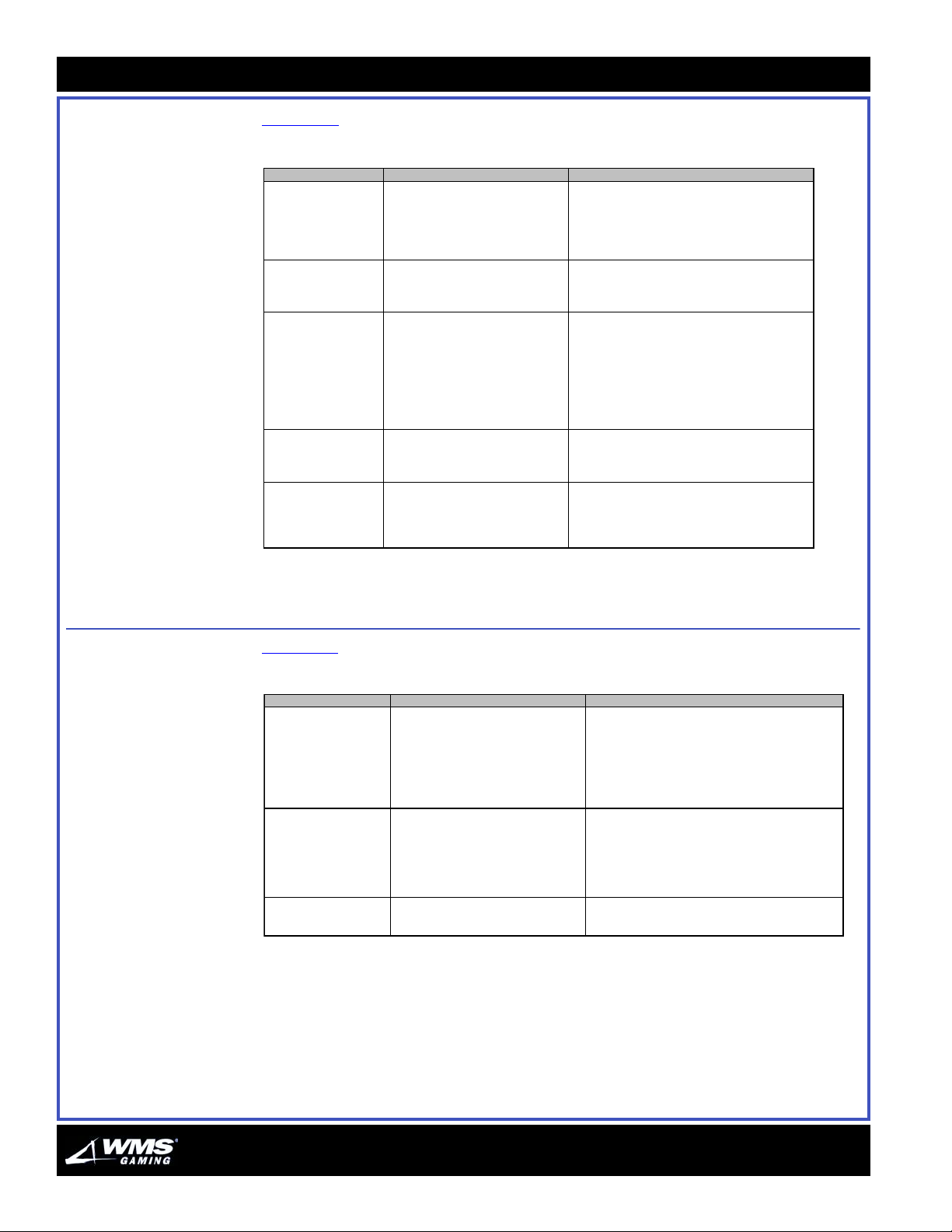
Door Tilt Guide Table 2-12 provides the door tilts and their solutions.
Table 2-12 Door Tilts.
Symptom Probable Cause Solutions
"Bi ll Door Open" appears
on monitor
"Drop Door Open"
appears on monit or
"Bill Jam Service Door
Open" appears on moni t or
"Logic Door Open"
appears on monit or
"Mai n Door Op en"
appears on monit or
1. Open Bil l Door. 1. Close and lock St ac ker (bottom B V ) Door.
2. Maladjust ed BV OPEN switch. 2. Adjust switch.
3. Bent switc h m ount i ng brac ket. 3. Straight en or replac e bracket .
4. Bad B ILL DOOR swit ch. 4. Replac e switc h.
5. Bad B ILL DOOR swit ch wiring. 5. Repair or replac e wiring.
6. Bad B ILL DOOR swit ch cable. 6. Repair or replac e switc h cable.
1. Open Drop Door. 1. Close and l ock Drop Door.
2. Bad DROP DOOR s witch. 2. Replace swit ch.
3. Bad DROP DOOR switch wiring. 3. Rewire switch.
4. Bad DROP DOOR s witch c abl e. 4. Repair or replac e switch cable.
1. Maladjust ed switch. 1. Adjust switch.
2. Open Bil l Jam S ervice Door. 2. Close and lock door.
3. Bad B ILL JAM S ERVICE switch. 3. Replace switc h.
4. Bent BILL JAM SERVICE switch
mounting brac ket.
5. Bad BILL JAM SERVICE switch
wiring.
6. Bad BILL JAM SERVICE switch
cable.
1. Open Logic Door (Card Cage Door). 1. Close Card Cage Door.
2. Bad CAG E DOOR s witch. 2. Replace swit ch.
3. Bad CAGE DOOR switch wiring. 3. Rewire switch.
4. Bad CAG E DOOR s witch c abl e. 4. Repair or replac e switc h cable.
1. Open Main Door or Printer Door. 1. Close and lock Mai n Door and Print er Door.
2. Bad door s witch (Main Door or Pri nt er
Door).
3. Bad door s witch wiring. 3. Repair or replace wiring.
4. Bad door s witch c able. 4. Repair or replace s wi t ch cable.
4. Bend bac k brack et .
5. Rewire switch.
6. Repair or replace s wi t ch cable.
2. Replace s witch .
Hard Meter Tilt Guide
Tabl e 2-13 provides the hard meter tilts and their solutions.
Tab le 2- 13 Hard Meter Tilts.
Symptom Probable Cause Solutions
All hard meters fail to
increment
"Mechanical Meter #%d
Failure" appears on display
(where "#%d" equals the
number of the meter)
One or more hard meters
doesn't increment. No tilt
message appears.
1. Bad Meter Board cable. 1. Check these DC voltages at Meter Board end of 12-
2. Bad Meter Board. 2. Volta
3. Bad CPU-NXT Board. 3. Replace fault
Bad connection to meter:
* 19" Slant and Upright, Bartop: Meter
numbers proceed from left to right and top
to bottom. Top meters: 1, 2, 3. Bottom
meters: 4, 5, 6.
* 17" Upright: Meter numbers proceed
from top to bottom.
Bad meter. Locate the bad meter and replace it. (Refer to
pin Meter Board cable:
* +12V, pin 11
* +5V, pin 2
Missing voltage or voltage reads low: Repair or replace
cable.
e checks OK: Replace Meter Board.
board.
1. With power off, perform a continuity test between
CPU-NXT Board, Meter Board and meter.
2. Tighten loose connections.
3. Repair or replace bad cable.
jurisdiction rules about meter replacement.)
16-015713-00
Page 30
Chapter 2: Troubleshooting
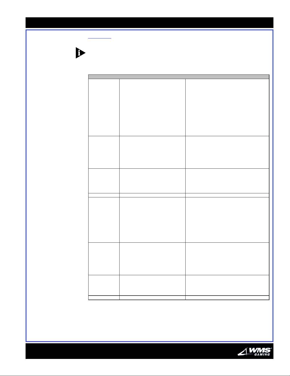
Monitor Guide Table 2-14 provides the monitor tilts and their solutions.
NOTICE: The monitor may flicker when the system is being booted up. This is normal
and does not require any troubleshooting.
Tab le 2- 14 Monitor Tilts.
Symptom Probable Cause Solutions
Dark screen (no
pictur e or raster).
M issing color (r ed,
green, or blue).
* Pict ur e is far too
short to fill screen.
* Screen displays
horizontal line, but no
picture.
Keystoned raster. Short ed turns in monitor yoke. Replace yoke or monitor.
Screen only displays
raster.
1. Misaligned blind mating c onnec tor. 1. Align connect or plug an d jac k .
2. W r ong br ightness or cont r ast settings. 2. Correc t brightness and contrast con trol settings.
3. No power to monitor. 3. No output on pow er c hassis for 120 VAC: r eplac e power
4. No video signal to monitor. 4. Check for b ad or loose video cable. Repair or r eplac e
5. Bad monitor po wer supply. 5. Replac e po wer supply or monitor.
6. Bad hor izontal output tr ansistor or damper
diode.
7. O ver-voltage condition at flyback
transfor mer activated shutdown circuit .
8. F aulty star tup circuit. 8. Test monitor with alternate power supply. Then r epair
1. Misaligned blind mating c onnec tor. 1. Align connect or plug an d jac k .
2. I mproper c olor adjustment. 2. Display color bar s in Administration Mode. Adjust
3. O pen c olor gun driver transistor. 3. Replace transistor or monitor .
4. Br ok en cable to neck board . 4. Repa ir or r eplac e c able or nec k boa r d.
5. F ault in monitor's v ideo pr ea mp. 5. Replace preamp (an IC in most monitor models) or
6. Low emission from one color gun. 6. Rejuvenate CRT.
1. I mproper vert ic al size setting. 1. Adjust v er tical size cont rol.
2. Bad verti c al power amp in monitor. 2. Replace vertical power transistors or int eg r ated circuit.
3. Bad deflection amp in monitor. 3. Replace vertical deflection int egr ated circuit ( in many
1. Misaligned blind mating c onnec tor. 1. Align connect or plug an d jac k .
2. Disconnected video cable. 2. W ith power OF F, inspect U2 and U3 on t he CP U- NXT
3. Br ok en wir es inside v ideo cable. 3. Check video cable t o make sure it is properly seated.
4. Dead video preamp power supply in
monitor.
5. Bad video preamp IC in monitor . 5. Replac e power supply components or monitor.
chassis.
bad cable. S e c ur e loose cable.
6. Replace transistor . Test damper diode, retrace tuning
capacit ors and associated components before r estar ting
monitor.
7. W ith var lac , test monitor at r educ ed i nput volt age.
Replace out- o f-spec components in horizontal circuit .
startup c ir c uit.
chassis and neck board c o lor c ontrols.
monitor.
monitors, defle c tion and power stages are part of the same
integrated circuit .).
Board. Make sure chips are not r eversed (accor ding to
labels on board). Reposition improper ly inserted chips.
M ak e sure pins are not bent.
4. Repair or replace video c able.
6. Replace integrated cir c u it or monitor.
2-9
16-015713-00
Solid colors seem to
be contaminated with
shades of wrong
color.
Splotc hes of c o lor
mar picture.
Corrupt ed scree n. Asy nc hr ono us cable not installed. In stall asynchronous cable.
M onitor purity or static c o nvergence magnets
are out of alignment.
Pict ur e tube picked up magnetic c har ge. 1. Use exter na l degaussing coil to degauss monitor (built -
1. Enter A dministrat ion Mode. Display each purity (solid
color) screen.
2. F or eac h scr een, rotate pur ity magnets (around CRT
neck) until color is as pure as possible.
3. Check your work by displaying the crosshatch pattern.
Grid lines should be white. Read just magnets until at least
center lines are white. Lines at extreme edges may display
some slight color c ontamination.
in coil probably is not powerf ul enough to restore pict ur e
fidelity).
2. T est monito r with purity (solid color) and color bar s
screens in Administrat ion Mode.
Page 31
2-10
Power Gui de
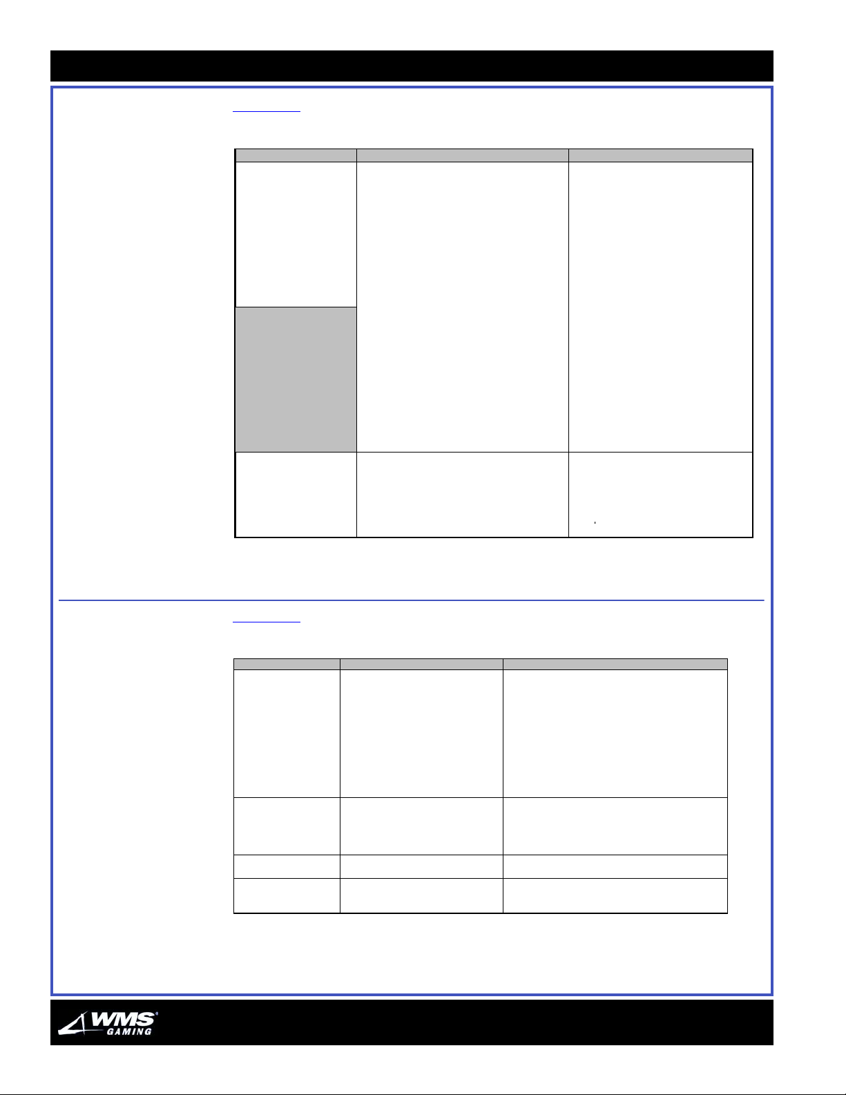
Power Guide Table 2-15 provides the power tilts and their solutions.
Tab le 2- 15 Power Tilts.
Symptom Probable Cause Solutions
Partial Power Failure: 1. Missing card cage power: 1. Wrong or Missing Voltages: c heck
• Monitor is black, but
seems to have high
voltage (Screen may
flicker occasionally)
NOTES:
•+5VI refers to the +5Vvolt switcher in the power
supply. (Measure between
+5VI and GND(l). Other
•+18V supply is only linear
supply. Its LED remains
on for few seconds after
you shut off power. Other
supplies are switchers.
Total Power Failure: 1. Fuse on PDU. 1. Replace fuse.
• Dead monitor
• CPU does not start up
2. Power supply failure: Check voltages at
DC power connector:
• Pin 13 = PFD (Power Fail Detect). 2b. Proper voltages at power supply,
• Pin 16 = +5VI* • Pin 14 = +12V.
• Pin 15 = –12V • Pin 17 = GND(I).
• Pins 18, 19 = Approx 22VDC, No load.
• Pins 20-22 = +5V.
• Pins 1-12, 23, 24 = GND.
(NOTE: These voltages have +/ –
tolerances.)
3. Improperly inserted EPROMs.
2. AC power line in. 2. Turn on circuit breaker or service
3. Bad PDU output. 3. Check all PDU outputs with a digital
4. Faulty line cord. 4. Replace line cord.
backplane, cables, power supply.
Repair or replace bad parts.
2a. Wrong or Missing Voltages at
power supply: Replace bad switching
power supply.
but not at card cage: Replace power
cables.
3. EPROMS inserted backwards may
be damaged. Replace them.
electrical outlet.
voltmeter. Repair or replace power
Printer Tilt Guide Tabl e 2-16 provides the power tilts and their solutions.
Tab le 2- 16 Printer Tilts.
Symptom Probable Cause Solutions
1. "PRINTER ERROR" 1. Several possible causes:
2. Pri nt e r is print i ng
"garbage"
Uneven type densi t y
Type is too light
* Ribbon t ears
* Printhead jams
* Tickets smudge
* Printer switch is turned off.
* Unplugged or damaged power cord.
* Unplugged or damaged flat cabl e.
* Paper jam s ins i de pri nter.
2. Pri nter buffer contai ns unusabl e data. 2. Cycle power off and on. P erform pri nt e r t est.
1. B ad ribbon cartridge. 1. Replace cartri dge.
2. Uneven from left to righ t : Maladj usted
Plat en G ap.
3. Uneven from top to bot tom:
Maladj us ted Printhead Angl e.
1. B ad ribbon cartridge. 1. Replace cartri dge.
2. Mal adj usted P l at e n Gap 2. Adjus t Platen G ap.
Print head angl e i s wrong for paper type
you us e.
1. Solutions to "PRINTER JAM" tilt:
* Make sure that printer switch is on.
* Reconnec t unplugged c ab le. Repair or replace bad
cable.
* Clear paper jams. If mes sage persi sts, c l ear error
message from internal memory.
(NOTE: W hen handling print er, never lift printer by print er
beak. If you adj u s t printer, you m ay need to real i gn
printer beak wit h p ri nter bezel.)
2. Adj ust P l aten Gap.
3. Adjust Printhead Angle.
Adjust P ri nt hea d A ngl e Lever.
16-015713-00
Page 32
Chapter 2: Troubleshooting
y
y
y
j
y
y
g
y
y
(
y
g
g
)
y
y
(
y
y
(
y
y
2-11
Static RAM Tilt Guide
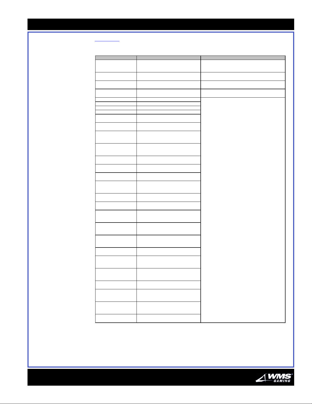
Table 2- 17 provides the Static RAM tilts and their solutions.
Tab le 2- 17 Static RAM Tilts.
Message on Display Probable Cause Solutions
"Battery Fail" Failure of static RAM backup battery. 1. Replace the battery.
"Video Memory Heap
Corrupt"
"Insufficient Video
"
Memor
"Memory Cleared" (top of
candle flashes slowly)
"CRC Corrupt" OS data corrupt.
"Heap Corrupt" Corrupt heap memor
"Heap Full" Full heap memor
"Deck Corrupt" Bad deck of cards.
"Recoverable Game Log
Data Corruption"
"RAM Signature
Corruption"
"RAM Signature Corruption
(Main and Aux)"
"Auxiliary RAM Signature
Corruption"
"Main Meter Corruption" "Main Meter data copy corrupt. Game will
"Main Meter Corruption
Data Lost)"
"Unrecoverable Game
Meter Corruption"
"Auxiliary Main Meter
Corruption"
"Jurisdictional Jumper
ed!"
Chan
"Illegal Denomination Set" Game denomination is incorrect or invalid;
"Configuration Data
Corruption (Main and
"
Aux
"Configuration Data
Corruption"
"Auxiliary Configuration
Data Corruption"
"Operating System Data
Corruption
"Operating System Data
Corruption"
"Auxiliary Operating
System Data Corruption"
"Card Deck Data
Corruption
"Card Deck Data
Corruption"
"Auxiliary Card Deck Data
Corruption"
"Event Log Data
Corruption (Data Lost)"
Data Lost)"
Data Lost)"
Video memor
Video memory is full. Verify the 2M chip is installed. If it is and message still
You
Game Log Data is corrupt. Game will soft
RAM clear and erase
Critical RAM signature data is corrupt.
Game must be RAM cleared.
Game Log Data is corrupt. Game will soft
RAM clear and erase game log.
Aux copy of RAM signature data is
corrupt. Game will attempt to restore from
Main cop
to restore from Aux copy."
tr
Critical Main Meter data is corrupt. Game
must be RAM cleared.
Unrecoverable Game Meter corruption.
Aux copy of Main Meter data is corrupt.
Game will attempt to restore from Main
cop
Jurisdictional Jumper has been changed;
RAM clear the game.
RAM clear the
Critical configuration data is corrupt.
Game will attempt to restore from backup
in Soft RAM Clear.
Main copy of critical configuration data is
corrupt. Game will attempt to restore from
Aux cop
Aux copy of critical configuration data is
corrupt. Game will attempt to restore from
Main cop
Critical system data is corrupt. Game
must be RAM Cleared.
Main copy of critical system data is
corrupt. Game will attempt to restore from
Aux cop
Aux copy of critical system data is corrupt.
Game will attempt to restore from Main
cop
Card deck data is corrupt. Game must be
RAM Cleared.
Main copy of card deck data is corrupt.
Game will attempt to restore from Aux
cop
Aux copy of card deck data is corrupt.
Game will attempt to restore from Main
cop
Event log data is corrupt. Game will erase
event log data in soft RAM Clear.
error. Bad card or software error; change card.
ust cleared the static RAM. Press DIAGNOSTIC button.
area.
area.
ame log.
.
.
ame.
.
.
.
.
.
.
2. Use the proper RAM Clear Chip to replace data lost
due to the batter
displays, change board.
Static RAM procedure:
1. Clear the static RAM.
2. Save game play, pricing and other locationprogrammed information to the central system (or write
it down).
3. Shut off power, remove CPU Board and replace
battery today.
4. Same symptoms repeat: Check backup battery
voltage: Less than 3.6V? Replace battery and reclear
static RAM. More than 3.6V? Check or replace MAX791
chip (5880-13649-00).
5. Rerun startup tests.
6. If error messages still appear, the static RAM may be
bad. Try replacing it and retest machine.
failure.
16-015713-00
Page 33
2-12
Static RAM Tilt Guide
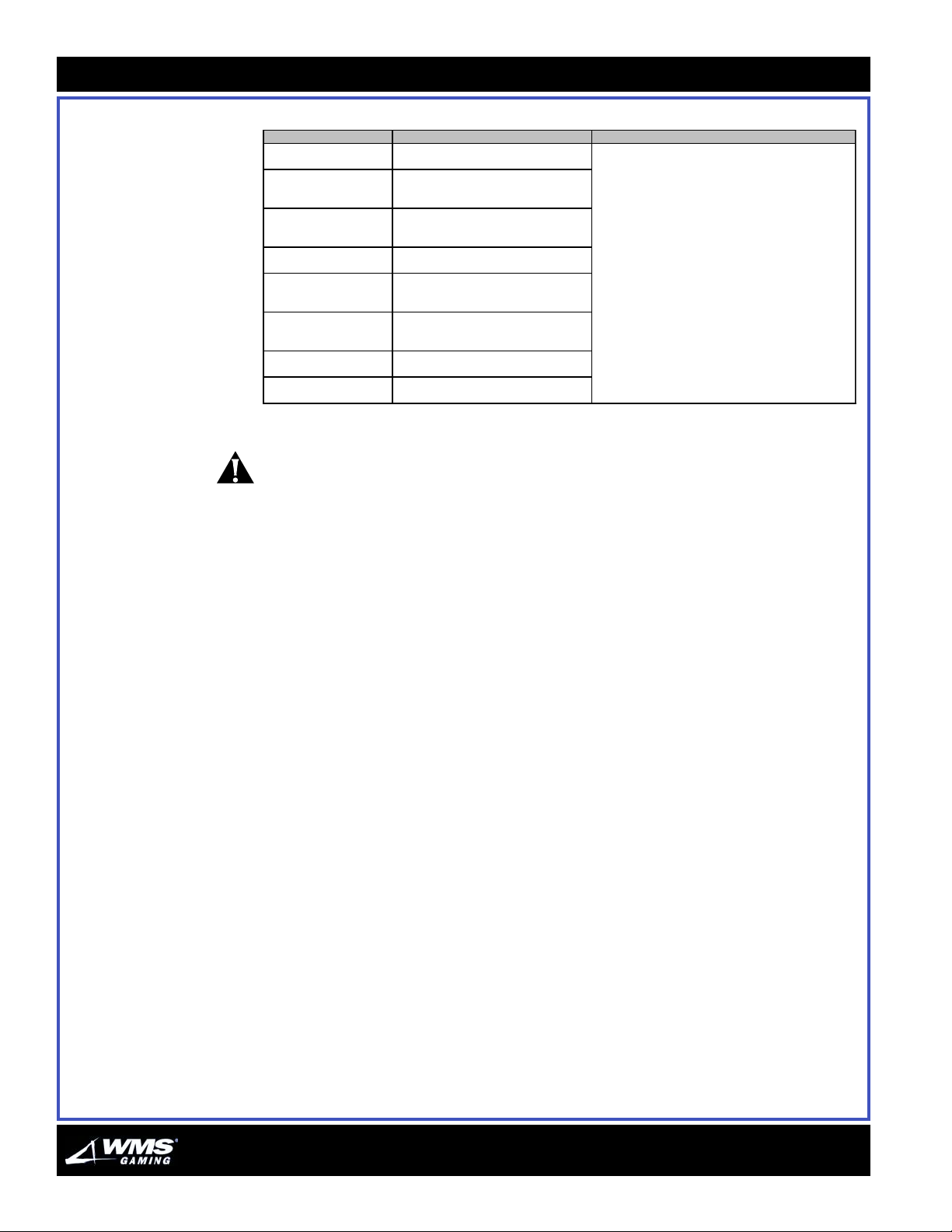
Table 2-12 Static RAM Tilts (cont’d).
Message on Display Probable Cause Solutions
"Event Log Data
Corruption (Data Lost)"
"Event Log Data
Corruption"
"Auxiliary Event Log Data
Corruption"
"Touchscreen to Confirm
Soft RAM Clear"
"Press Diagnostic Button
to Exit Soft RAM Clear
(Data Lost)"
"Press Diagnostic Button
to Exit Soft RAM Clear
(Data Restored)"
"Keno Range Error" Keno specific game error (only occurs in
"Invalid Card Value" Illegal card drawn (occurs in games that
CAUTION: An explosion can occur if the battery is incorrectly replaced. Replace only
with the same or equivalent type recommended by the manufacturer. Dispose of
used batteries according to the manufacturer instructions.
Event log data is corrupt. Game will erase
event log data in soft RAM Clear.
Main copy of event log data is corrupt.
Game will attempt to restore from Aux
copy.
Aux copy of event log data is corrupt.
Game will attempt to restore from Main
copy.
Game memory corrupted and soft RAM
Clear required.
Soft RAM Clear complete but data has
been lost.
Soft RAM Clear complete; data restored
from backup storage.
Keno games)
use card class)
See Static RAM procedure in Solutions column on
preceding page.
16-015713-00
Page 34
Chapter 2: Troubleshooting
2-13
Touch Screen Tilt Guide
Table 2-13 provides the touch screen tilts and their solutions.
Tab le 2- 13 Touch Screen Tilts.
Symptom Probable Cause Solutions
Touching screen resul ts
in no response or
erroneous behavior.
"No Touch Screen
Respons e" appears on
monit or s creen.
"Touch S creen
Communicati ons Fault"
appears on s creen.
Touch Sc reen wil l not
calibrate or stay in
calibration.
1. Improperly adj us ted blind
mati ng connector.
2. B ad or loos e Touch S creen
interfac e c abl e.
3. B ad or loos e m oni tor/Touch
Sc reen cable.
4. Touch Screen is badl y out
of calibrat i on.
5. B ad Touch S c reen B oard. 5. Replace Touch S creen Board.
6. B ad Touch S c reen. 6. Replac e moni tor.
7. Loc ked up Touch Sc reen
(you removed and replaced
monit or with power on).
8. No power. 8. Check for proper volt ages on Touch Sc reen
1. Improperly adj us ted blind
mati ng connector.
2. B ad or loos e touch Screen
interfac e c abl e.
3. B ad or loos e m oni tor/Touch
Sc reen cable.
4. B ad Touch S c reen B oard. 4. Replace Touch S creen Board.
1. Improperly adj us ted blind
mati ng connector.
2. B ad or loos e Touch S creen
interfac e c abl e.
3. B ad or loos e m oni tor/Touch
Sc reen cable.
4. B ad Touch S c reen i nt erface
cable.
5. B ad Touch S c reen B oard. 5. Replace Touch S creen Board.
1. A djust connec t or for ti ght fit .
2. Loos e interface c abl e: rec onnect i t securely .
For broken c abl e: repai r or replac e i t .
3. Loos e m oni tor c able: rec onnect i t securely .
For broken c abl e: repai r or replac e i t .
4. Rec al i brat e Touch Sc reen using t he
instructions in Software A dm i ni s trati on.
7. Turn game off and on, then recali brat e Touch
Screen.
board at P2: 1=+ 5V, 2= gnd, 3-12V, 4= +12V. If
voltages are abs ent: repl ac e power c abl e. If
voltages are pres ent: replace Touch Screen
Board.
1. A djust connec t or for ti ght fit .
2. Loos e interface c abl e: rec onnect i t securely .
For broken c abl e: repai r or replac e i t .
3. Loos e m oni tor c able: rec onnect i t securely .
For broken c abl e: repai r or replac e i t .
1. Dry i t wi t h hai r dry er for five mi nutes. Do not
clean i t wi t h am m oni a-bas ed cleaners . Us e
alcohol i nst ead.
2. Replac e m oni t or.
3. Repair or replac e Touch S creen Cable.
4. Repair or replac e i nt erface cable.
16-015713-00
NOTICE: If the Touch Screen requires calibration when the Setup Menu is not
accessible, refer to the procedure, “Calibrating the Touchscreen without Accessing
the Setup Menu,” in Chapter 4, Software Administration.
Page 35

AUGUST 2005
C
HAPTER
M
3
AINTENANCE
16-015714-00
Table of Contents OVERVIEW ........................................................................................................................................ 3-2
SERVICING AND TRANSPORTING CIRCUIT BOARDS ................................................................................. 3-2
COLLECTION AND SUPPLY................................................................................................................... 3-4
Collecting Bills from the Bill Validator .........................................................................................3-4
COLLECTING COINS............................................................................................................................ 3-6
COIN VALIDATOR................................................................................................................................3-8
BILL VALIDATOR............................................................................................................................... 3-13
GLASS AND LAMPS..........................................................................................................................3-19
MONITOR........................................................................................................................................ 3-21
POWER DISTRIBUTION UNIT (PDU)....................................................................................................3-23
PRINTER......................................................................................................................................... 3-24
TOUCH SCREEN ............................................................................................................................... 3-34
Reassembling the Bill Validator ...................................................................................................3-5
Reading Electromechanical Meters ............................................................................................3-7
Removing the Coin Validator........................................................................................................3-8
Reassembling the Coin Validator.............................................................................................. 3-11
Bill Validator LEDs...................................................................................................................... 3-13
Cleaning...................................................................................................................................... 3-13
Simple Repairs........................................................................................................................... 3-17
Clearing Bills from a WBA ......................................................................................................... 3-18
Removing Buttons and Replacing Bulbs .................................................................................. 3-19
Reassembly ................................................................................................................................ 3-20
Replacing the Tower Light Bulb ................................................................................................ 3-20
Reassembling the Tower Light.................................................................................................. 3-20
Removing the Monitor ............................................................................................................... 3-21
Reassembling the Monitor ........................................................................................................3-22
Replacing the Power Distribution Unit Fuse ............................................................................ 3-23
Reassembling Power Distribution Unit Fuse............................................................................ 3-23
Changing Paper on the Printer ................................................................................................. 3-24
Replacing the Ithaca 70 Printer Firmware ............................................................................... 3-27
Replacing the Ithaca 70 Fuse................................................................................................... 3-32
Cleaning the Printer ................................................................................................................... 3-33
Cleaning the Touch Screen .......................................................................................................3-34
Page 36
3-2
Overview
Overview WMS Gaming Video Lottery Terminals (VLT) function optimally with periodic
maintenance. The following pages contain recommendations for maintenance and
service, as well as general peripheral upkeep for running a terminal that is free of
avoidable service calls.
CAUTION: Disconnect the power supply cord from the outlet before servicing to
avoid electrical shock.
Servicing and Transporting Circuit Boards
This section provides procedures for servicing and transporting circuit boards.
ESD: Always transport a circuit board within a static shielding bag. The static
shielding bag protects the circuit board from the destructive static charge that
emanates from your body or clothes, and from walking across a specific kind of
surface. The location(s) where the board is packed and unpacked also require
proper ESD protection.
Follow the steps below to transport a circuit board:
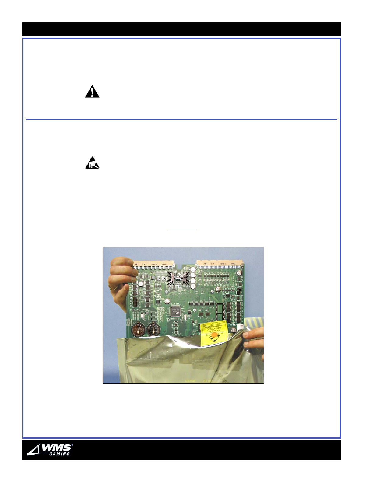
1 While properly grounded, hold the edge of the circuit board and slide it into a
static shielding bag, Figure 3-1
Figure 3-1 Sliding the circuit board into a static shielding bag.
.
AUGUST 2005
Page 37
Chapte r 3: Mai ntenance
3-3
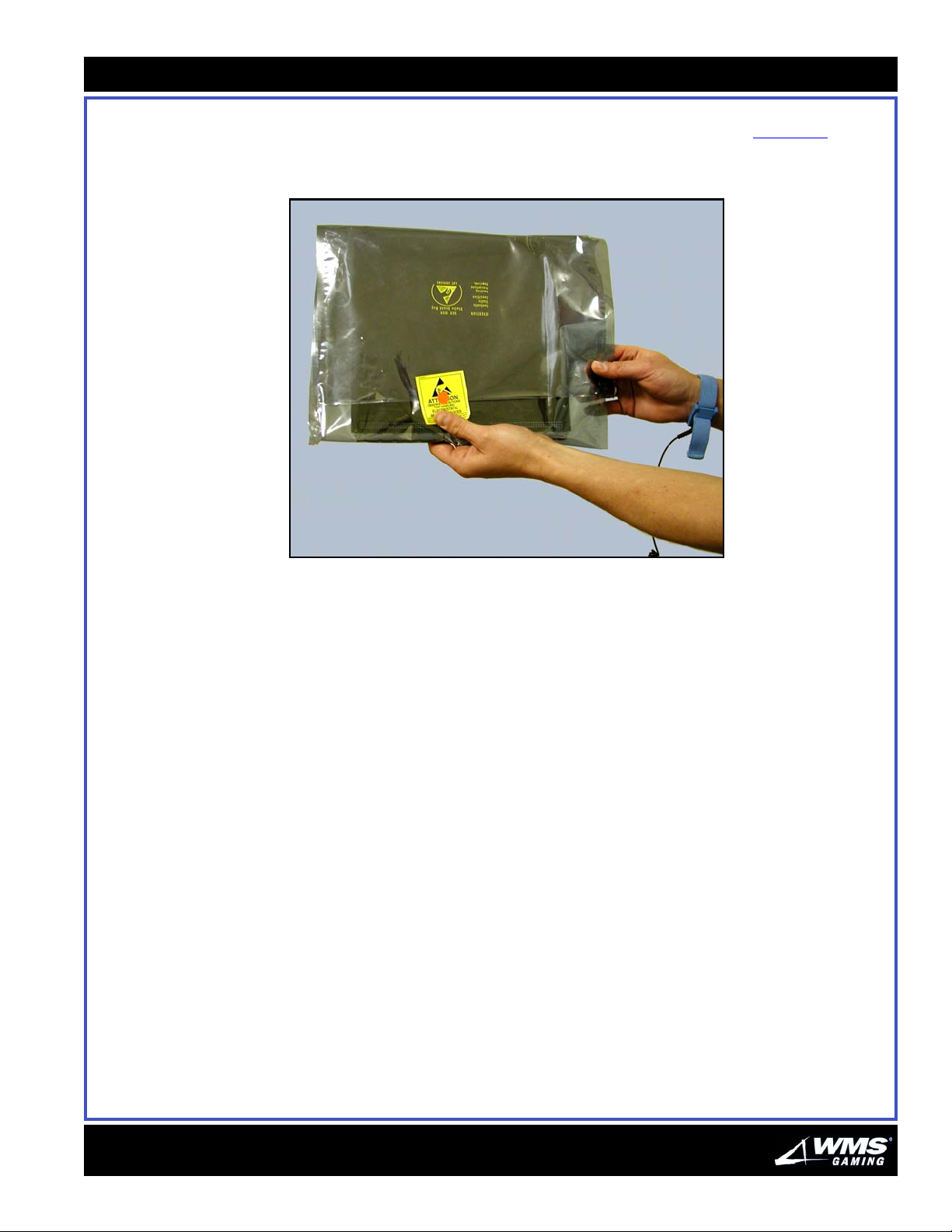
2 Close the static shielding bag with its zipper, if equipped, or tightly fold over the
end of the bag so the circuit board is completely surrounded, Figure 3-2
. Use an
anti-static sticker to seal the bag.
Figure 3-2 Closing the static shielding bag.
3 Carefully transport the circuit board so that it is not repeatedly sliding within the
static shielding bag. Do not transport through areas with high levels of static
electricity and electrical discharges, especially near or around air conditioning
equipment.
4 Confirm that the destination location is prepared as an ESD protective
environment. An ESD conductive mat and grounded ESD wrist strap are the
minimum requirements.
5 While properly grounded, open the static shielding bag.
6 Hold the edge of the circuit board and slide it out of the static shielding bag.
7 Place the circuit board on an ESD conductive mat to perform maintenance.
16-015714-00
Page 38
3-4
Collection and Supply
Collection and
Supply
Collecting Bills from
the Bill Validator
This section provides the following procedures for collection and supply of the VLT.
NOTICE: Be sure to follow your jurisdiction's procedures for logging currency
collection.
Follow the steps below to collect bills from the Bill Validator:
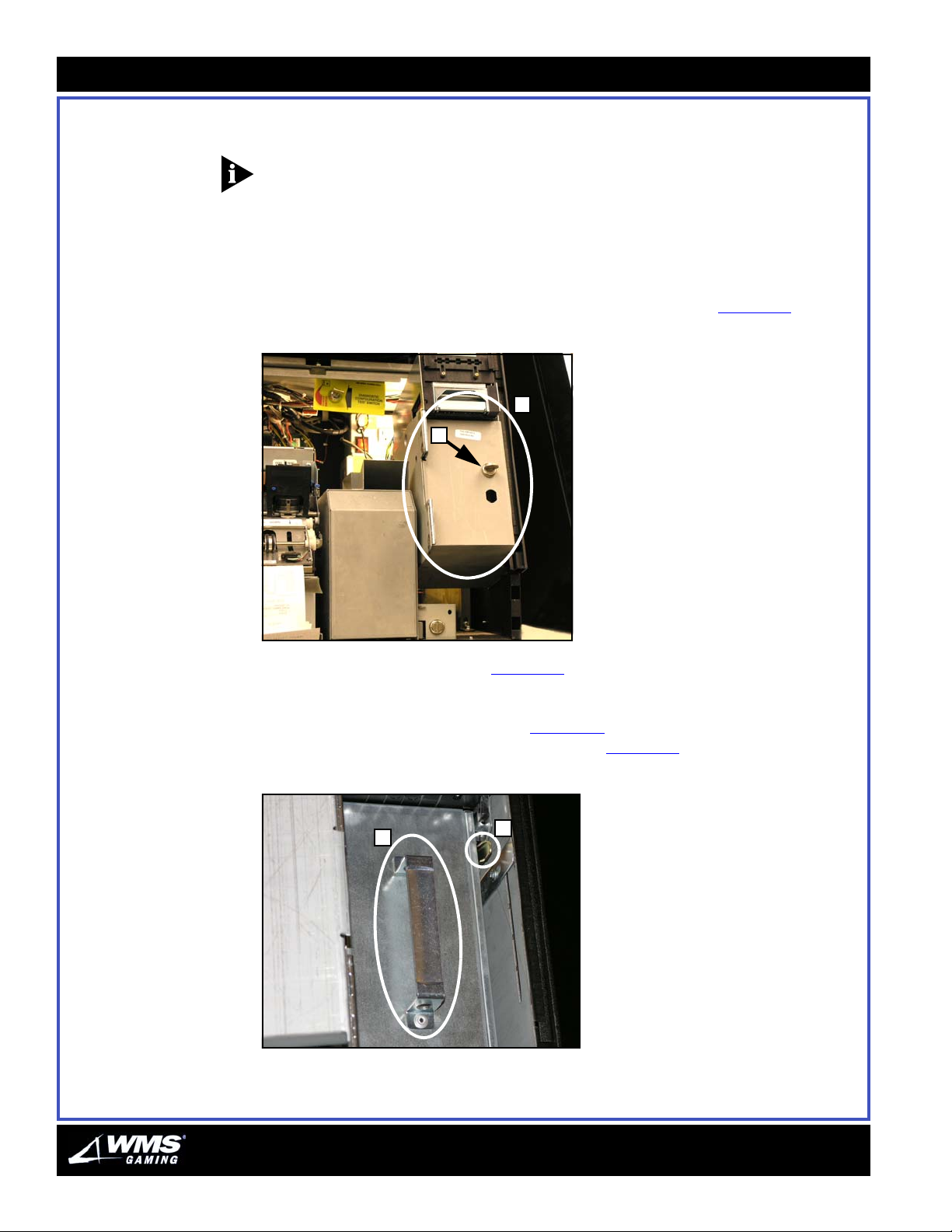
1 Unlock and open the belly door.
2 Locate the Bill Validator door on the right side of the cabinet, Figure 3-3
Figure 3-3 Bill Validator door.
A
B
(A).
3 Unlock the Bill Validator lock, Figure 3-3 (B), with your key.
4 Open the Bill Validator door.
5 Lower the Cash Box release lever, Figure 3-4
pull the box out of the acceptor by its handle, Figure 3-4
Figure 3-4 Cash Box release lever.
B
A
(A), to free the Cash Box and then
(B).
6 Unlock the Cash Box with the key and remove the bills.
AUGUST 2005
Page 39
Chapte r 3: Mai ntenance
3-5
Reassembling
the Bill Validator
Follow the steps below to reassemble the Bill Validator:
1 Slide the empty, locked Cash Box into the Bill Validator.
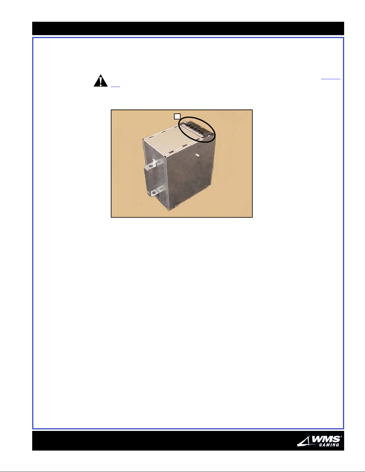
CAUTION: Take care not to install the Cash Box upside-down. The bill access, Figure
3-5 (A), must face upward.
Figure 3-5 Bill access.
A
2 Tug on Cash Box handle to see that it is fully seated.
3 Close and lock Bill Validator door.
4 Close and lock belly door.
16-015714-00
Page 40
3-6
Collecting Coins
Collecting Coins Follow the steps below to collect coins:
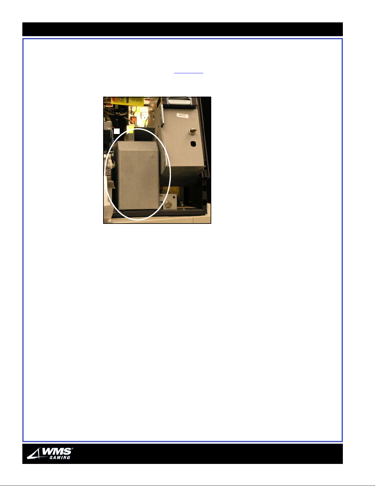
1 Open the Main Door with your key.
2 Slide out the coin box, Figure 3-6
toward you.
Figure 3-6 Coin box.
A
3 Empty the coin box.
4 Replace the coin box.
(A), by grasping the handle on top and pulling it
5 Lock the Main Door.
AUGUST 2005
Page 41
Chapte r 3: Mai ntenance
3-7
Reading
Electromechanical
Meters
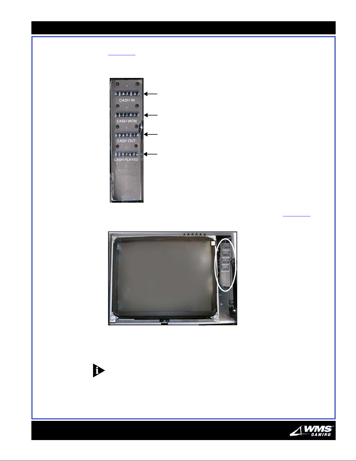
The VLT includes up to six non-resettable, electromechanical meters.
Figure 3-7
Figure 3-7 Electromechanical
(Hard) Meters.
depicts the meters.
Meter 1
Meter 2
Meter 3
Meter 4
Electromechanical meters are located to the right of the monitor, Figure 3-8, (A).
Figure 3-8 Location of meters.
A
Meters can be read from outside the machine, through an access window to the
right of the monitor screen. Follow procedures and regulations set up by your
jurisdiction.
NOTICE: The number of meters and meter labels may differ between jurisdictions.
Make a permanent record of the number value on the original meter. Refer to your
jurisdiction's rules for recording meter readings.
16-015714-00
Page 42
3-8
Coin Validator
Coin Validator The G-13.6000 Coin Validator electronically compares an incoming coin to
acceptance bands stored within the 12 channels of the Bill Validator. Table 3- 1
explains the actions that result from this process.
Table 3-1 Incoming Coin Validator results.
If the incoming coin... then the coin...
matches the value in one of the channels enters the “accept” track.
does NOT match the value in one of the channels diverts to the “reject” track.
Removing the Coin
Validator
Follow the steps below to remove the Coin Validator.
1 Unlock and open the Front Door.
2 Switch game power at the PDU to STANDBY.
3 Remove the Coin Validator:
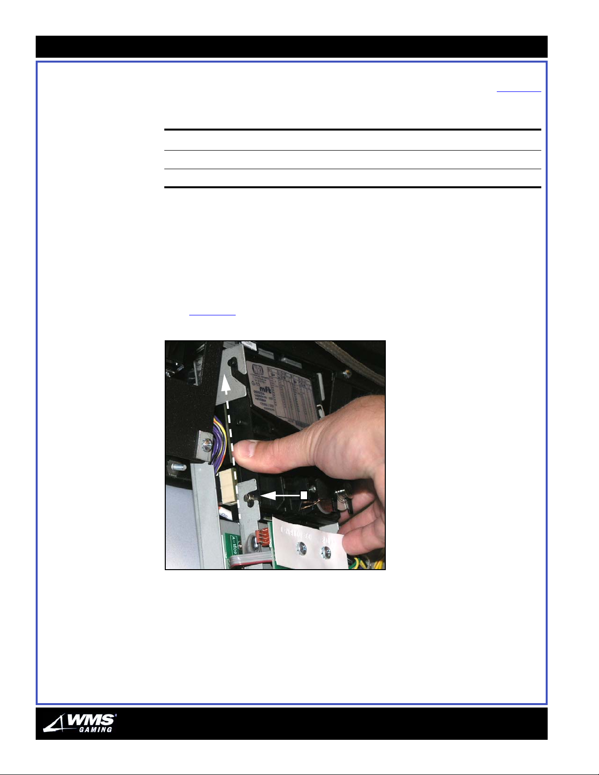
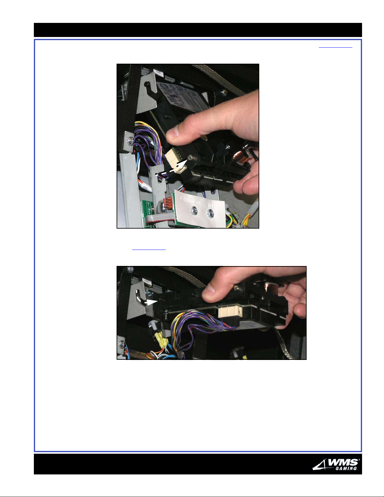
a Slide the Coin Validator upward so that the bottom studs clear their notches,
Figure 3-9
Figure 3-9 Sliding the Coin Validator upward.
(A).
A
AUGUST 2005
Page 43
Chapte r 3: Mai ntenance
b Pivot the bottom of the Coin Validator up and out of the bracket, Figure 3-10.
Figure 3-10 Pulling the bottom out.
3-9
c Pull the Coin Validator down from the top notches and out of the machine,
Figure 3-11
Figure 3-11 Pulling the Coin Validator out.
.
16-015714-00
Page 44
3-10
Coin Validator
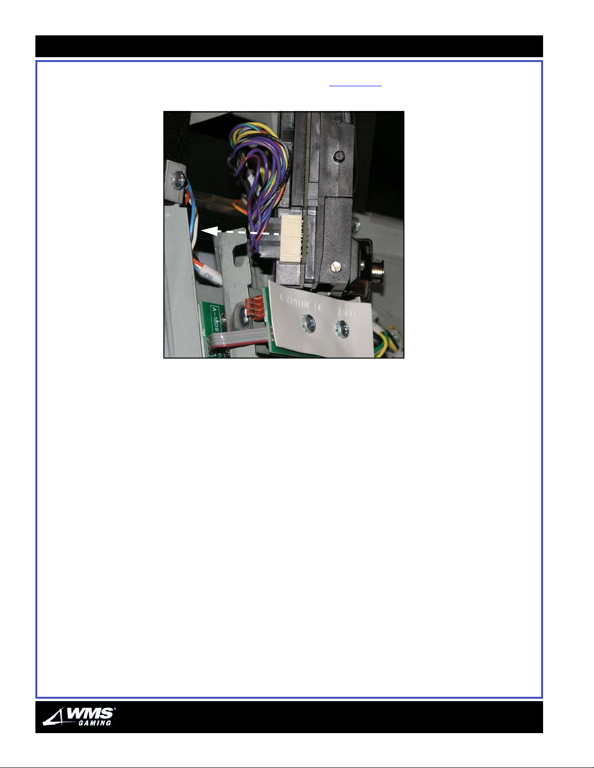
4 Remove the cable that connects the Validator and Hex Opto Board by grasping
the plug and pulling it off the jack, Figure 3-12
Figure 3-12 Removing the cable.
.
5 Set the Coin Validator aside for reassembly.
AUGUST 2005
Page 45
Chapte r 3: Mai ntenance
3-11
Reassembling the Coin
Validator
Follow the steps below to reassemble the Coin Validator.
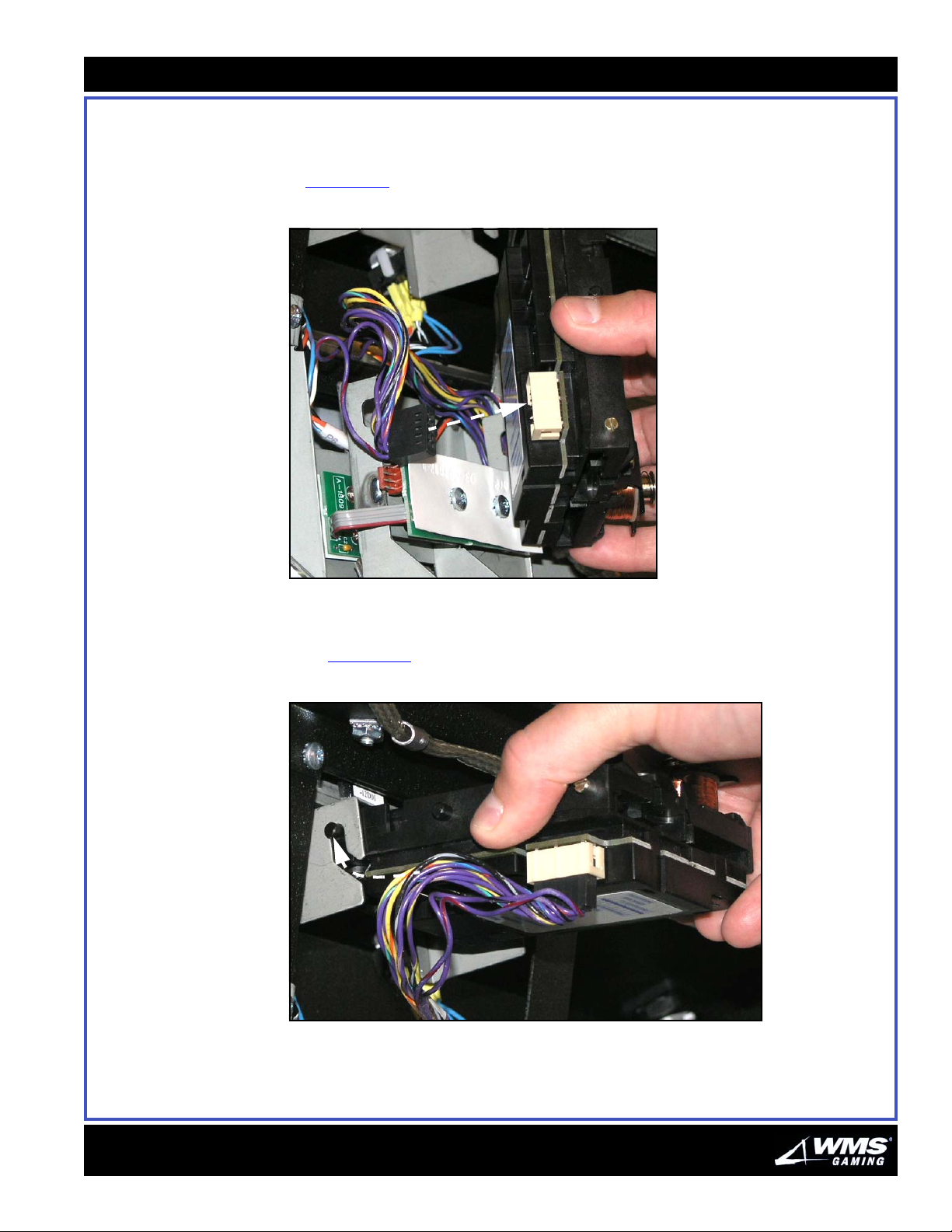
1 Plug in the cable that connects the Coin Validator and Hex Opto Board,
Figure 3-13
Figure 3-13 Plugging in the cable.
.
2 Mount the Coin Validator:
a Engage the top studs with the top bracket notches and slide them upward,
Figure 3-14
Figure 3-14 Sliding the studs upward.
.
16-015714-00
Page 46
3-12
Coin Validator
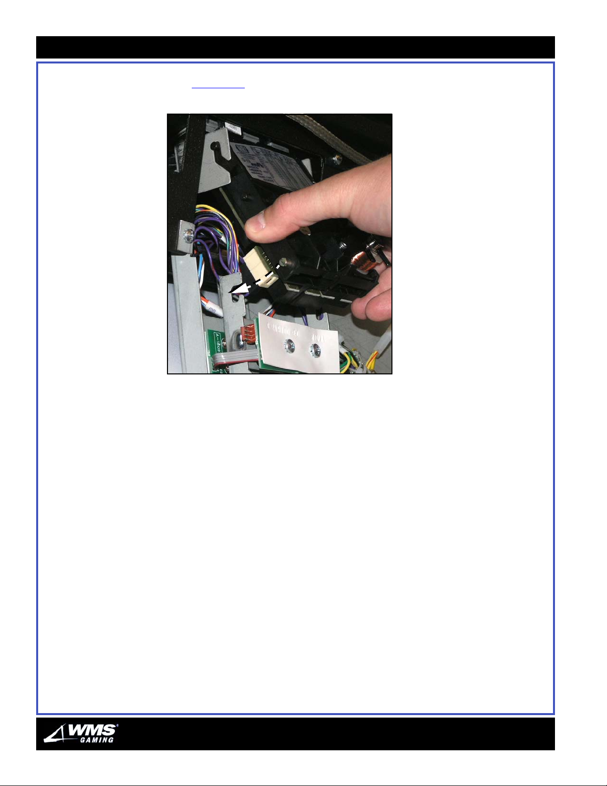
b Pivot and lower the base until the Validator engages the lower notches,
Figure 3-15
Figure 3-15 Lowering the base.
.
c Ensure that the Coin Validator seats properly.
3 Turn on VLT power at the PDU.
4 Close and lock the Front Door.
AUGUST 2005
Page 47
Chapte r 3: Mai ntenance
3-13
Bill Validator With proper handling and routine preventive maintenance, you can eliminate most
Bill Validator malfunctions. The following procedures assure top performance from
your JCM World Bill Acceptor
CAUTION: The JCM Bill Validator has one DIP switch bank with eight switches. The
factory setting for these DIP switches is all switches OFF. DO NOT CHANGE THESE
SETTINGS! Changes can cause the Bill Validator to malfunction.
Bill Validator LEDs Lit LEDs indicate that the Bill Validator is normal. If the LEDs go out, the VLT has
probably shut down the Bill Validator. Otherwise, all LEDs have burned out. This
situation is quite unlikely. Routinely check the LEDs to see if they remain lit. If not,
then service the validator.
Cleaning This section provides important information on keeping the Bill Validator clean.
Mag Sensor Parts
Regular cleaning is imperative. Sometimes iron filings adhere to the magnetic head
and head roller. Filings can prevent your Bill Validator from receiving bills.
®
(WBA) Bill Validator.
Lenses
To function properly, the Bill Validator must have clean sensor lenses and optical
reflectors. Table 3 - 2
Tab le 3- 2 Bill validator cleaning schedule.
If the validator takes in... then...
fewer than 4,000 bills per week clean it once a month.
4,000 bills per week or more clean it twice a month.
provides the cleaning schedule for the Bill Validator.
CAUTION: Never use the following to clean the Bill Validator unit:
an organic solvent such as thinner
compressed air
Cleaning Procedure
Perform the steps below to clean the Bill Validator.
1 Open the Main Door.
2 Pull down on the WBA handle and remove the WBA from the game. Pivot the Cash
Box forward.
3 Pull the Cash Box from the game.
16-015714-00
Page 48
3-14
Bill Validator
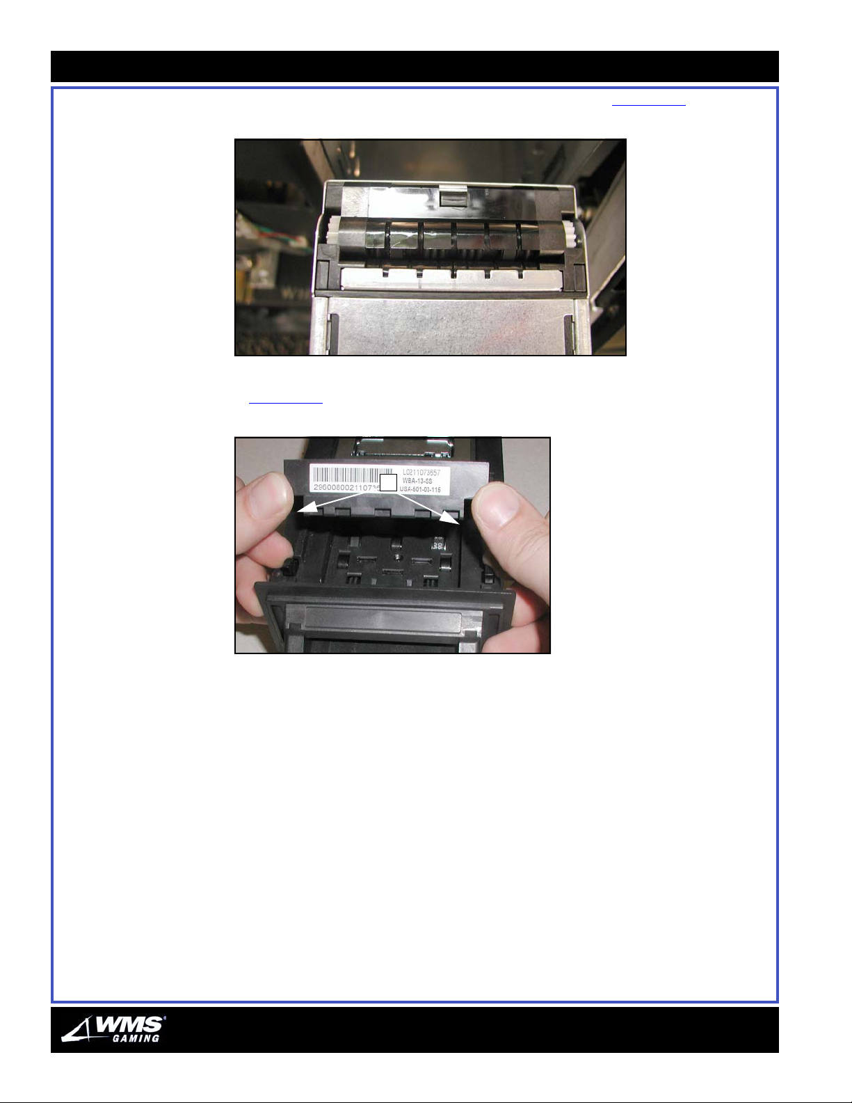
4 Using a soft brush, clear any dust or dirt from the gears, Figure 3-16.
Figure 3-16 WBA Cash Box gears.
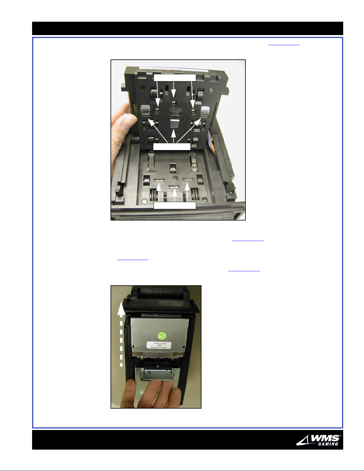
5 Lift the acceptor head by pulling forward on the tabs with your index fingers,
Figure 3-17
Figure 3-17 WBA Acceptor Head.
(A), and lifting the acceptor head with your thumbs.
A
AUGUST 2005
Page 49
Chapte r 3: Mai ntenance
6 Inspect the optical sensor lenses and magnetic heads, Figure 3-18.
Figure 3-18 WBA Optical Sensors and Magnetic Heads.
Sensor Lenses
Magnetic Heads
3-15
Sensor Lenses
7 Using a lint-free cloth lightly moistened in a mild detergent, clean the optical
sensor lenses and three magnetic heads, Figure 3-18
.
8 Once dry, replace the acceptor head, ensuring it clicks back into the tabs,
Figure 3-17
9 Open the transport by lifting the handle, Figure 3-19
Figure 3-19 Opening transport.
(A).
.
Sensor Lenses
Magnetic Heads
16-015714-00
Page 50
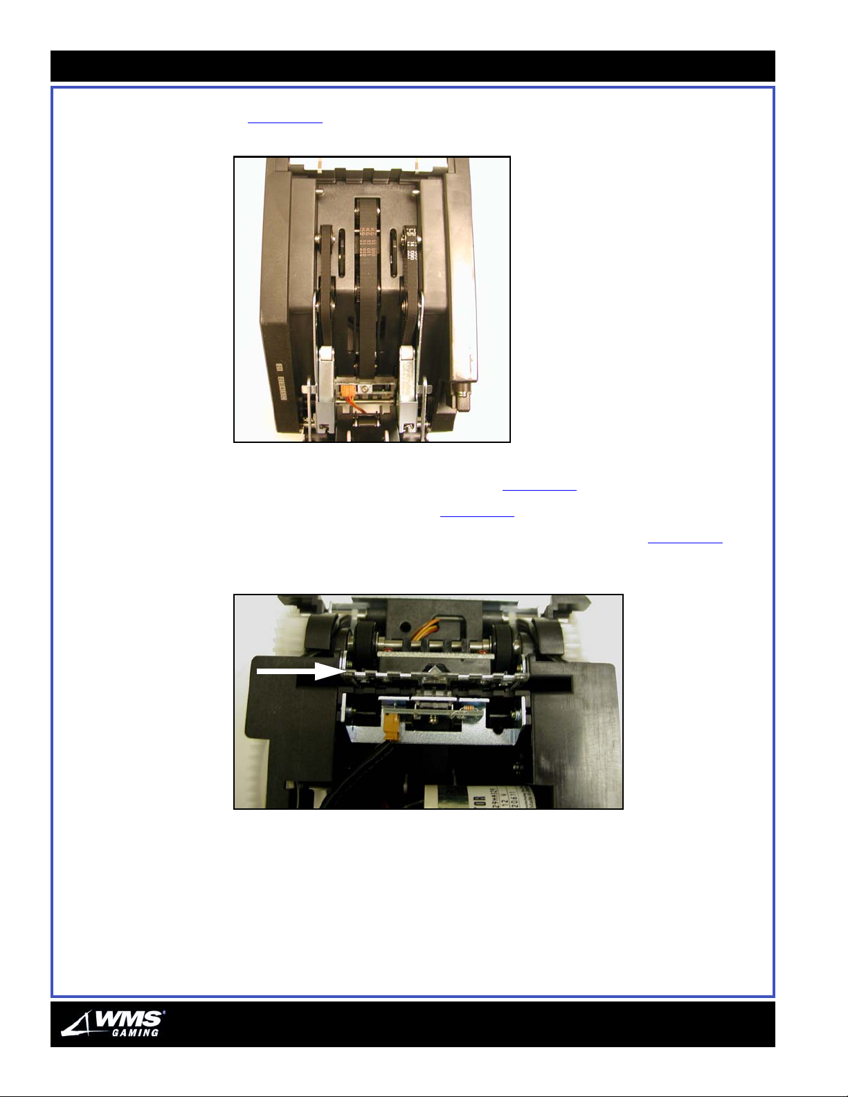
3-16
Bill Validator
10 Inspect the three timing belts to ensure they are not frayed or worn smooth,
Figure 3-20
Figure 3-20 Three WBA Timing Belts.
. If necessary, replace the belts.
Sensor Lenses
Magnetic Heads
11 Use the same mild diluted detergent mixture and lint-free cloth to gently wipe the
three belts as you rotate them by hand, Figure 3-20
12 Once dry, close the transport, Figure 3-19
.
13 Turn the transport over and verify that the clear plastic guide, Figure 3-21
.
, is not
damaged or chipped.
Figure 3-21 Clear Plastic Guide.
AUGUST 2005
Page 51
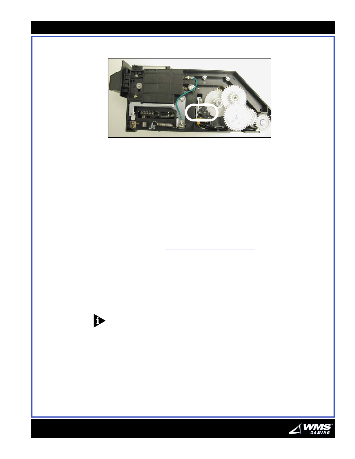
Chapte r 3: Mai ntenance
14 Inspect the timing encoder, Figure 3-22, for damage.
Figure 3-22 WBA Timing Encoder.
15 Replace the WBA in the game.
Simple Repairs This section provides important information on repairing the Bill Validator.
Observe Operation
To determine the cause of malfunctions and detect defective parts, routinely
observe validator operation. Before replacing parts, check that the connectors
engage properly. If the harness appears worn or damaged, replace it.
3-17
Fixing Validator Jams
Perform the steps below to fix validator jams.
1 Follow the steps in “
Cleaning Procedure” on page 13 to open the Bill Validator.
2 Remove the jammed bill.
3 If a bill is jammed near the inlet, then perform the following steps:
a Pull the release lever of the Cash Box.
b Remove Cash Box by its handle.
c Remove the jammed bill.
NOTICE: When replacing the Cash Box, ensure that the notch on the handle points
up.
16-015714-00
Page 52
3-18
Bill Validator
Clearing Bills
from a WBA
Perform the following steps to clear bills from a WBA.
1 Press on the front of the Bill Validator.
2 Unlock the bottom lock.
3 Slowly allow the door and stacker drawer to extend outward.
4 Pull the Bill Validator door out until the stacker drawer locks in the extended
position.
5 Push a cassette extraction tool into the side of the stacker drawer. The open end
on the tool must face down.
6 After the extraction tool mates with the bill cassette, slide out the extraction tool.
7 Slide an empty bill cassette into the side of the stacker drawer.
NOTICE: Do not use the extraction tool with this empty bill cassette. Also, take care
not to install the cassette upside-down. The open end on the empty cassette must
face upward.
8 Lift slightly on the stacker drawer, then press the stacker drawer release lever on
the bottom of the telescoping track.
9 Ease the stacker drawer back into the slant top. At the bottom, the drawer rests
on a spring.
10 Press the Bill Validator door until it reaches the end of its travel.
11 While holding the Bill Validator door to compress its spring, lock the Bill Validator
door.
AUGUST 2005
Page 53
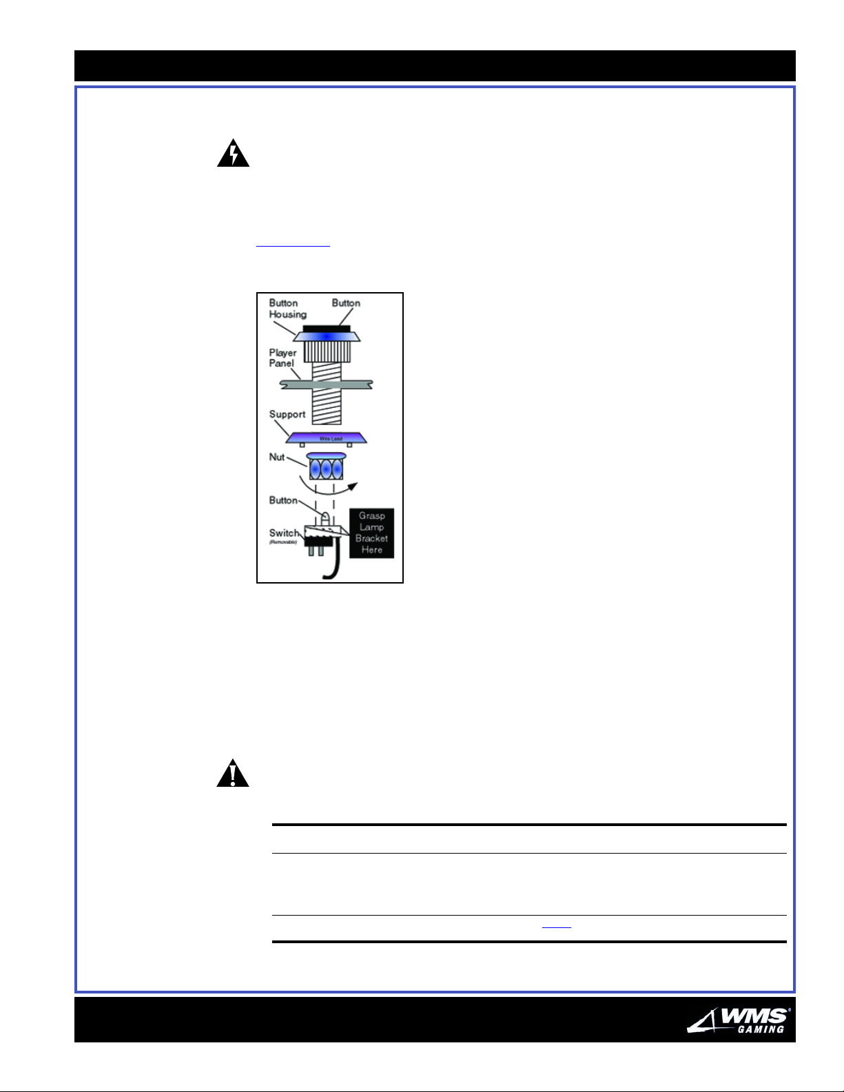
Chapte r 3: Mai ntenance
3-19
Glass and Lamps This section describes the maintenance and care of glass and lamps on the VLT.
WARNING: Switch game power at the PDU to STANDBY before working on WBA,
glass, and lamps. Otherwise, you risk potentially lethal shocks, serious burns, and
equipment damage.
Removing Buttons and
Replacing Bulbs
Perform the steps below to remove buttons and replace bulbs. Refer to
Figure 3-23
Figure 3-23 Typical Button Assembly.
as needed.
1 Unlock and open the Main Door.
16-015714-00
2 Switch game power at the PDU to STANDBY.
3 Grasp the lamp bracket just behind the plastic nut.
4 Firmly rock the lamp bracket back and forth until it disengages from the button
housing.
5 Pull the lamp bracket away from the button housing.
CAUTION: Take care not to bend switch leads.
6 Determine the following:
If you... then...
want to remove the button housing 1 unscrew the notched plastic nut
2 remove the nut support
3 lift the button housing off the Player Panel
do NOT want to remove the button housing proceed to step 7.
7 Grasp and pull the old bulb straight out.
Page 54
3-20
Glass and Lamps
Reassembly Perform the steps below to reassemble the bulbs.
1 Replace the bulb. Use a type CM86 or equivalent bulb (WMS P/N 24-8829).
2 Determine the following:
If you... then...
Replacing the Tower
Light Bulb
removed the button housing 1 replace it through the button hole, ensuring that the letters read
did NOT remove the button housing proceed to step 3.
right-side up.
2 replace the nut support from the button housing.
3 secure the button housing with the plastic nut, ensuring that the
serrated edge of the plastic nut faces the player panel.
3 Hold down the button and snap the lamp bracket back on. Test the button to
ensure that the bracket seats properly.
4 Switch on VLT power.
5 Close and lock the Main Door.
Follow the steps below to replace the tower light bulb.
1 Unlock and open the Main Door.
2 Switch game power at the PDU to STANDBY.
3 Using an 11/32 nut driver, remove the top nut from the tower light.
4 Remove the tower light dome.
5 Grasp and turn the bayonet bulb counter-clockwise. When the bulb disengages, it
pops out.
Reassembling the
Tower Li ght
Follow the steps below to reassemble the tower light.
1 Insert the new bulb in the socket.
CAUTION: Only replace the lamp with a type 1888 bulb! Other types may cause
damage.
2 Turn the bulb clockwise until it locks in place.
3 Replace the dome and top nut.
4 Tighten the nut with an 11/32 nut driver.
5 Switch on VLT power at the PDU.
6 Close and lock the Main Door.
AUGUST 2005
Page 55
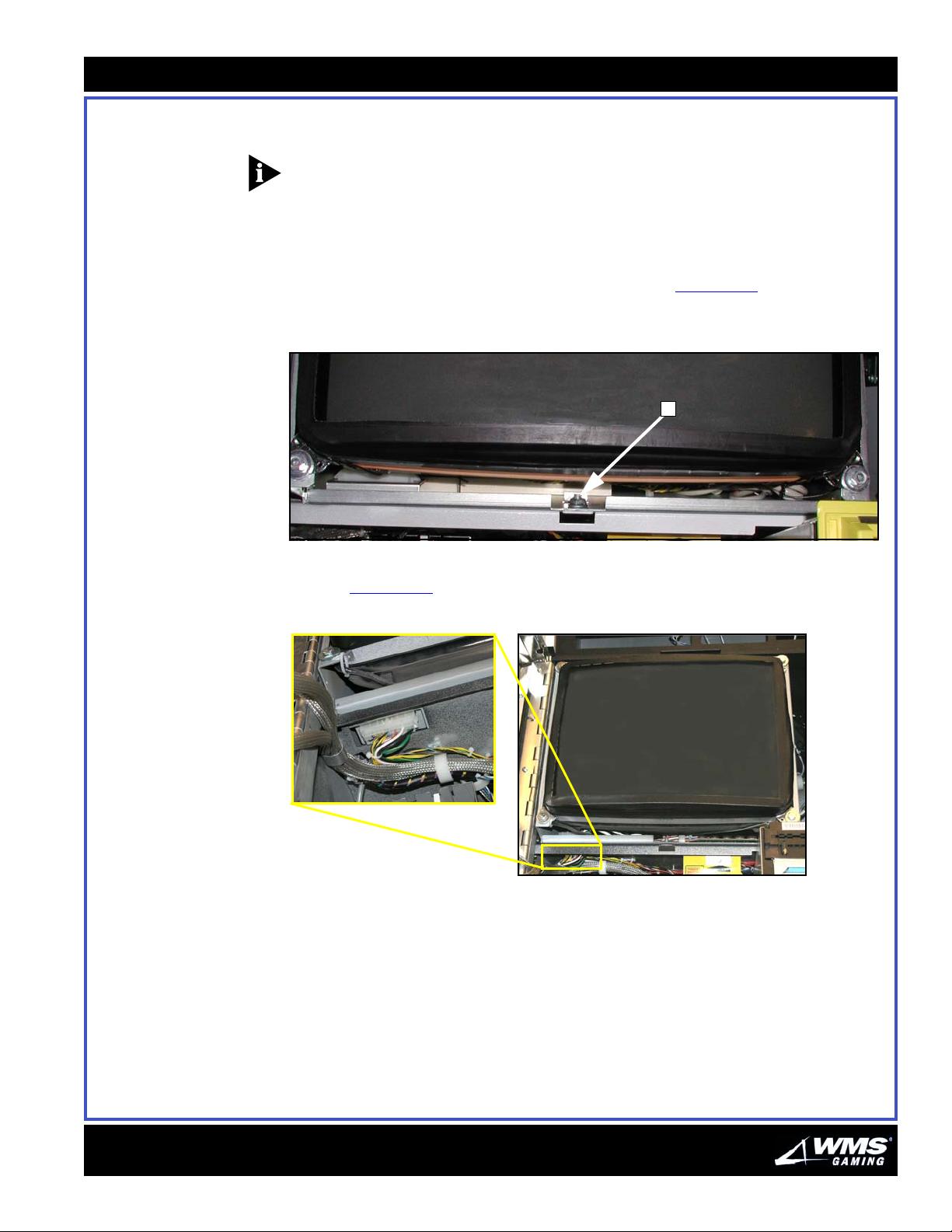
Chapte r 3: Mai ntenance
Monitor This section provides the procedures required to maintain the Monitor.
NOTICE: Proper monitor adjustment will compress the foam tape on the bezel from
50 to 70%.
Removing the Monitor Perform the steps below to remove the monitor.
1 Switch game power at the PDU to STANDBY.
3-21
2 Loosen but do not remove the 7/16 flange grip nut, Figure 3-24
(A), located at the
front of the monitor shelf, centered under the monitor.
Figure 3-24 Flange grip nut.
A
3 Locate the Molex minifit connector located under the left front side of the monitor
shelf, Figure 3-25
Figure 3-25 Molex mini-fit connector.
.
16-015714-00
Page 56
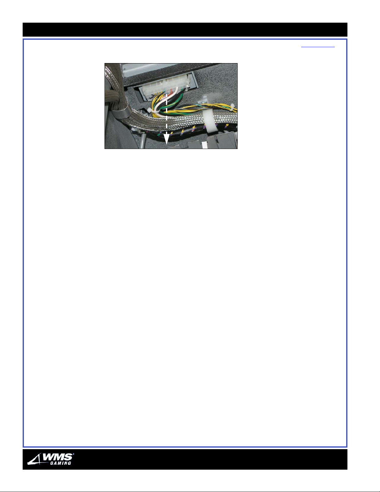
3-22
Monitor
4 Disconnect the Molex minifit connector by pulling it straight down, Figure 3-26.
Figure 3-26 Disconnecting Molex minifit connector.
5 Slide monitor forward till flange grip nut stops its forward progress (over the wide
part of the keyhole slot).
6 Lift monitor up and out of the VLT.
Reassembling the
Monitor
Perform the steps below to reassemble the monitor.
1 Place the monitor on the monitor shelf and slide it back until the flange grip nut
comes up through the keyslot.
2 Finger-tighten the nut.
3 Slide monitor to its forwardmost position on the shelf.
4 Close and latch main door to align the position of the monitor.
5 Carefully open the main door. Do not move the monitor.
6 Tighten flange grip nut.
7 Reconnect the Molex minifit connector through the monitor shelf opening to the
monitor.
8 Switch on VLT power at the PDU.
9 Close and lock the Main Door.
AUGUST 2005
Page 57
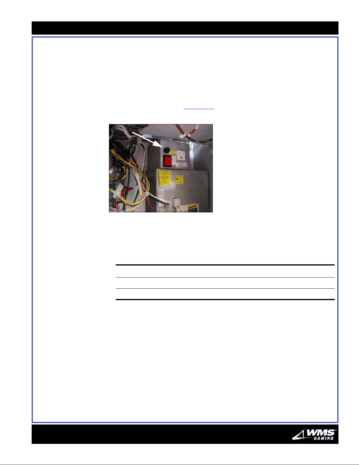
Chapte r 3: Mai ntenance
3-23
Power Distribution Unit (PDU)
Replacing the Power
Distribution Unit Fuse
This section provides the procedures required to maintain the Power Distribution
Unit (PDU).
Perform the steps below to replace the PDU.
1 Unlock and open the Main Door.
2 Switch game power at the PDU to STANDBY. The main power fuse is mounted on
the VLT's PDU panel box, Figure 3-27
Figure 3-27 Main power fuse.
.
Reassembling Power
Distribution Unit Fuse
3 Unscrew the plastic fuse knob.
Perform the steps below to reassemble the PDU fuse.
1 Determine the following:
If the VLT is in a... then...
120-volt area install a 4ASB, 250V fuse.
220 to 240-volt area install a 2ASB, 250V fuse.
2 Return the fuse knob to its position on the PDU front panel.
3 Twist the plastic fuse knob until it reengages.
4 Switch on the VLT power at the PDU panel box.
5 Close and lock the Main Door.
16-015714-00
Page 58
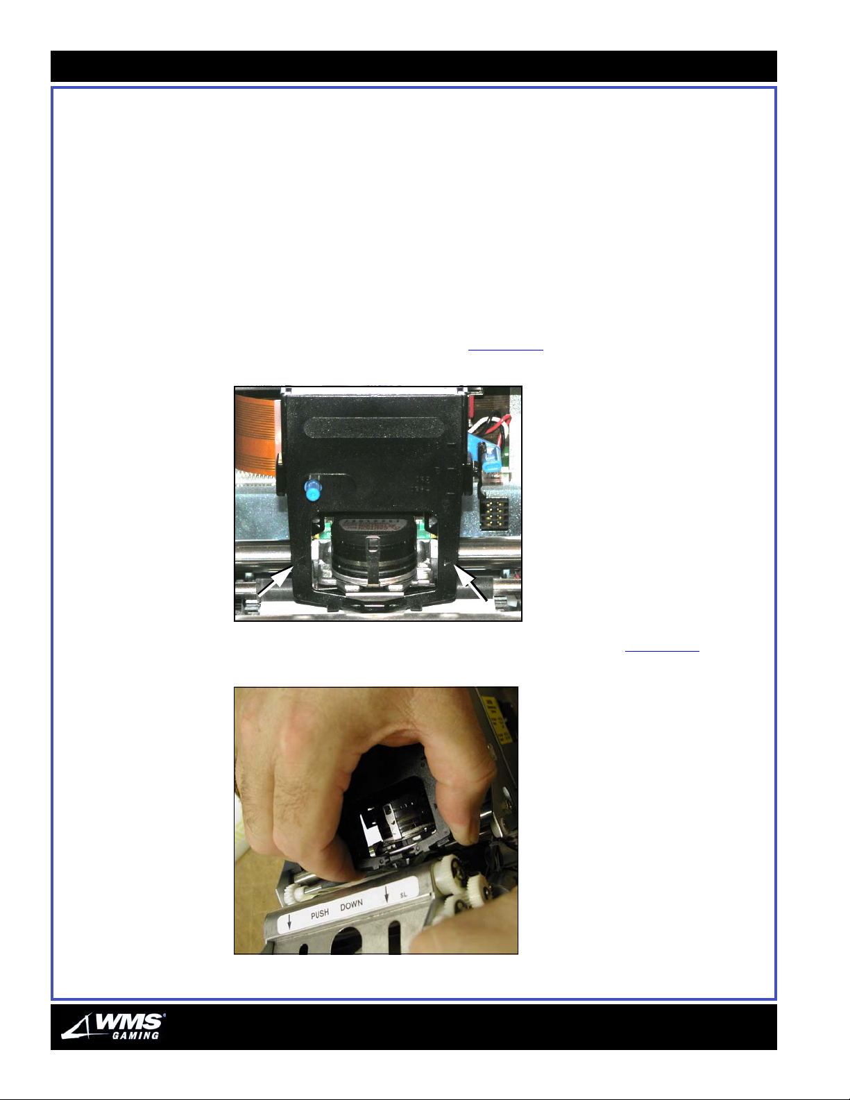
3-24
Printer
Printer This section provides the procedures required to maintain the Printer.
Changing Paper on the
Printer
When the game runs out of paper, a printer tilt displays on the game until new paper
is added and the game and printer are power cycled.
Complete the following steps when the Printer Out of Paper tilt displays.
1 Unlock and open the Main Door. The Main Door Open tilt displays. This tilt clears
after you finish loading the paper and close the Main Door.
2 Remove the printer ribbon cassette:
a Slide the printhead carriage assembly to the center.
b Holding the transport mechanism down on the PUSH DOWN label, grasp the
ribbon cassette by the arrows, Figure 3-28
Figure 3-28 Ribbon cassette arrow locations.
.
c Lifting the ribbon side first, pull out the entire cassette, Figure 3-29.
Figure 3-29 Removing the printer ribbon cassette.
AUGUST 2005
Page 59
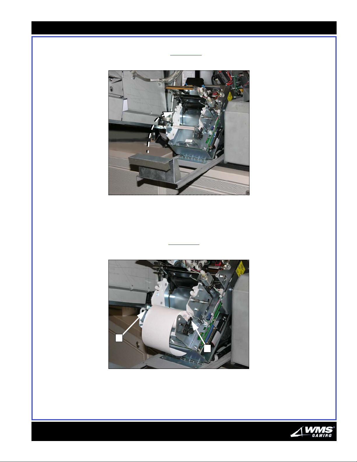
3 Slide the printer chassis out of the game.
Chapte r 3: Mai ntenance
3-25
4 Tilt the printer back, Figure 3-30
Figure 3-30 Tilting the printer back.
.
5 Remove and discard the used paper roll.
6 Ensure that the leading edge of the new paper roll is cut straight across, and that
no adhesive or stickers remain.
7 Place the new paper roll on the spool and seat the spool in the guides further
from the printhead, Figure 3-31
Figure 3-31 Seating the paper roll.
A
(A).
A
16-015714-00
Page 60
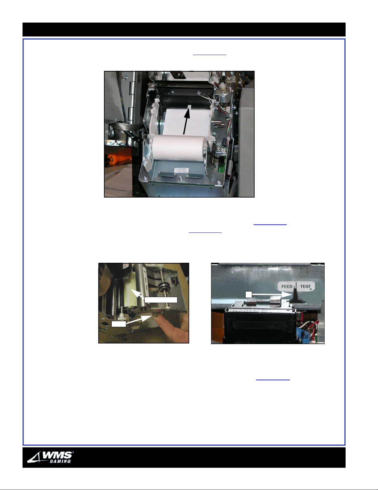
3-26
Printer
8 Feed the paper from the bottom of the roll up through the guides until the paper
emerges past the printhead, Figure 3-32
Figure 3-32 Paper feed direction.
.
9 Power cycle the printer.
10 While lifting the lever on the side of the transport, Figure 3-33
FEED | TEST toggle switch, Figure 3-34
(A), to the FEED position. The leading
, press the
edge feeds through the print head and down through the transport.
Figure 3-33 Properly feeding paper. Figure 3-34 FEED/TEST toggle switch.
leading edge
lever
A
11 Replace the printer ribbon cassette by guiding the ribbon into the printer head,
then push the cassette back into place.
12 Press the FEED | TEST switch to the right (TEST), Figure 3-34
. This realigns the
print head and cuts the paper. The printer is ready to print.
13 Close and lock the VLT. The game displays a jurisdiction-specific tilt code until the
connection with the host is reestablished. The host automatically clears this tilt
after three to four minutes.
AUGUST 2005
Page 61
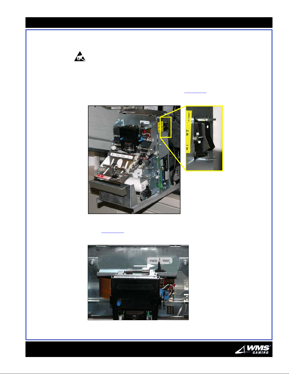
Chapte r 3: Mai ntenance
3-27
Replacing the Ithaca
70 Printer Firmware
Ithaca periodically releases firmware updates for the Model 70-series printer. This
section provides information on how to replace Ithaca 70 Printer Firmware.
ESD: Ensure that proper ESD practices are utilized. See the About This Guide
chapter of this document for the ESD safety procedure.
Viewing the printer firmware version
Perform the following steps to view the printer firmware version currently running:
1 Power the printer Off at the power switch, Figure 3-4
Figure 3-4 Printer power switch.
.
16-015714-00
2 While holding the FEED | TEST switch to the left (FEED), power the printer back
On, Figure 3-5
Figure 3-5 FEED | TEST toggle switch.
.
Page 62
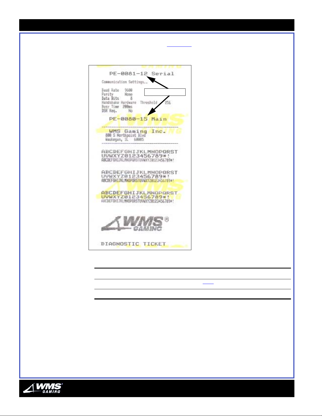
3-28
Printer
3 Verify that a Diagnostic ticket prints with the current firmware version on the Main
and Serial firmware EPROMs, Figure 3-6
Figure 3-6 Diagnostic ticket.
Firmware versions
.
4 Determine the following:
If a change or update... then...
is required proceed to step 5
is NOT required you have completed this procedure
5 Ensure that an ESD-safe area is available for your use.
6 Power the printer Off at its power switch.
AUGUST 2005
Page 63
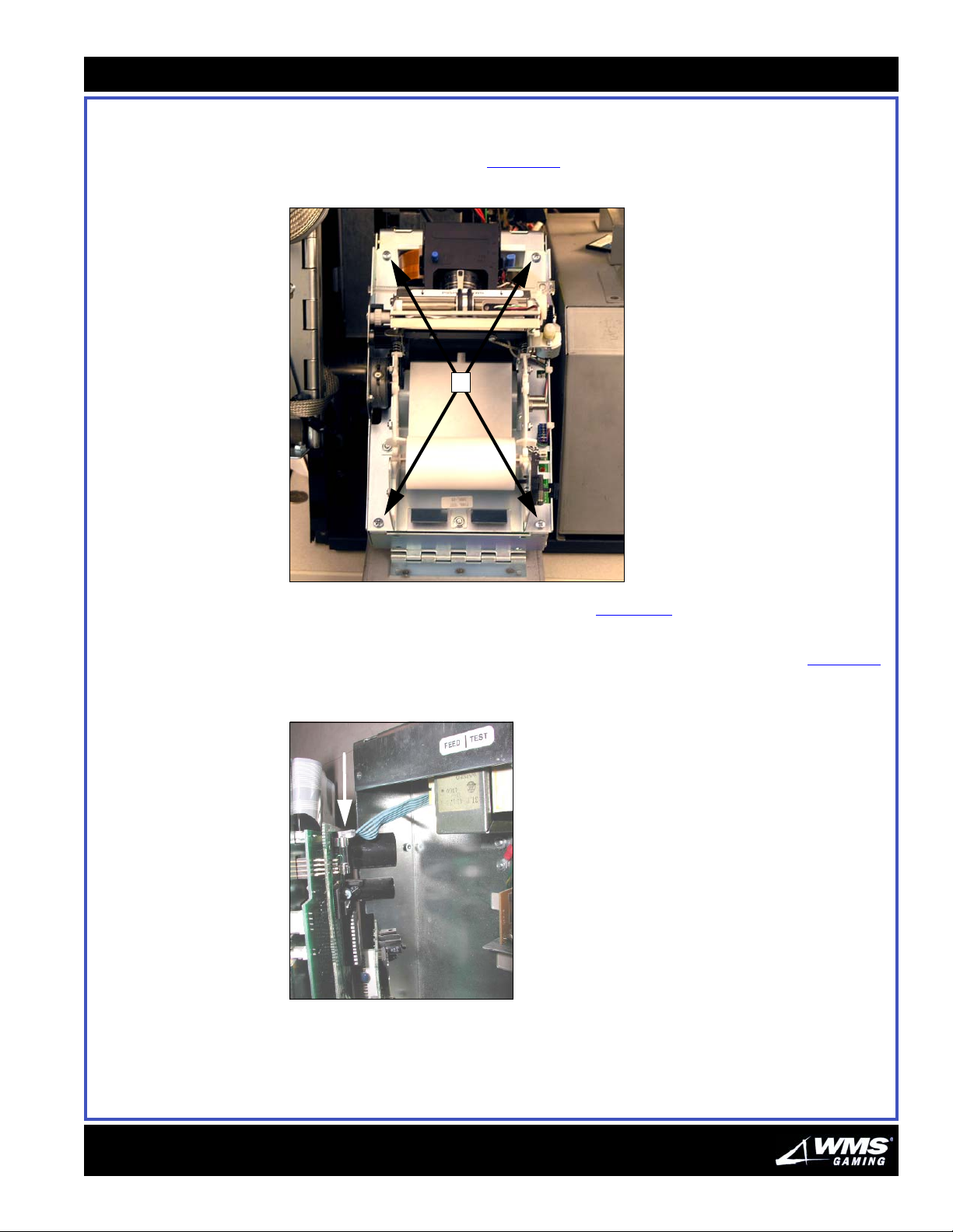
Chapte r 3: Mai ntenance
3-29
7 Slide the printer chassis out of the game.
8 Using a Phillips screwdriver, remove the four captive screws securing the printer
assembly to the chassis, Figure 3-7
Figure 3-7 Printer chassis screws.
A
(A).
9 Carefully lift out the printer assembly, Figure 3-7, to access the power supply
cable.
10 Disconnect the power supply cable at the top of the printer assembly, Figure 3-8
Figure 3-8 Disconnecting the power
supply cable.
.
16-015714-00
Page 64
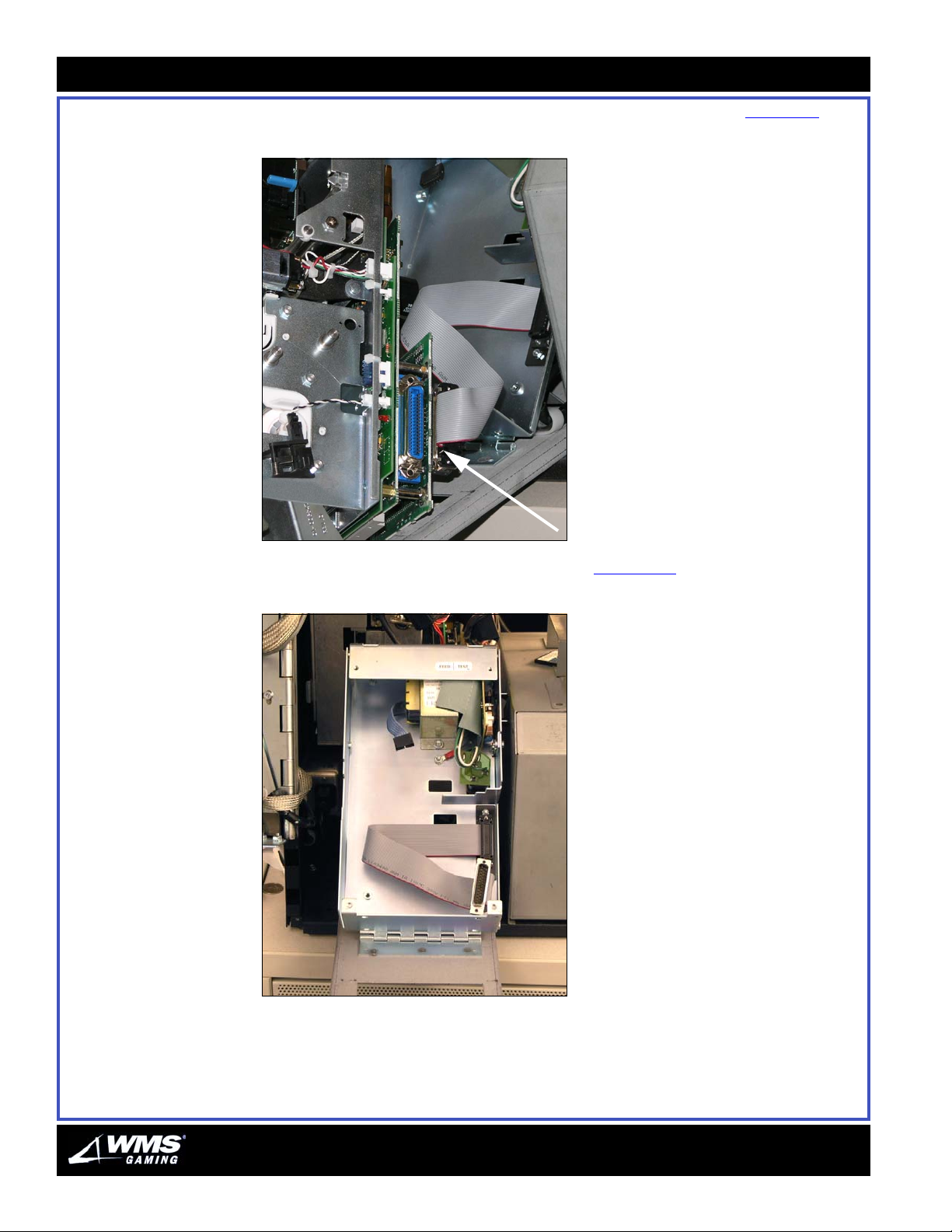
3-30
Printer
11 Disconnect the data cable at the bottom of the printer assembly, Figure 3-9
Figure 3-9 Disconnecting the data cable.
12 Lift the printer assembly out of the chassis, Figure 3-10.
Figure 3-10 Empty printer chassis.
13 Move the printer assembly to the ESD-safe work area to continue.
AUGUST 2005
Page 65
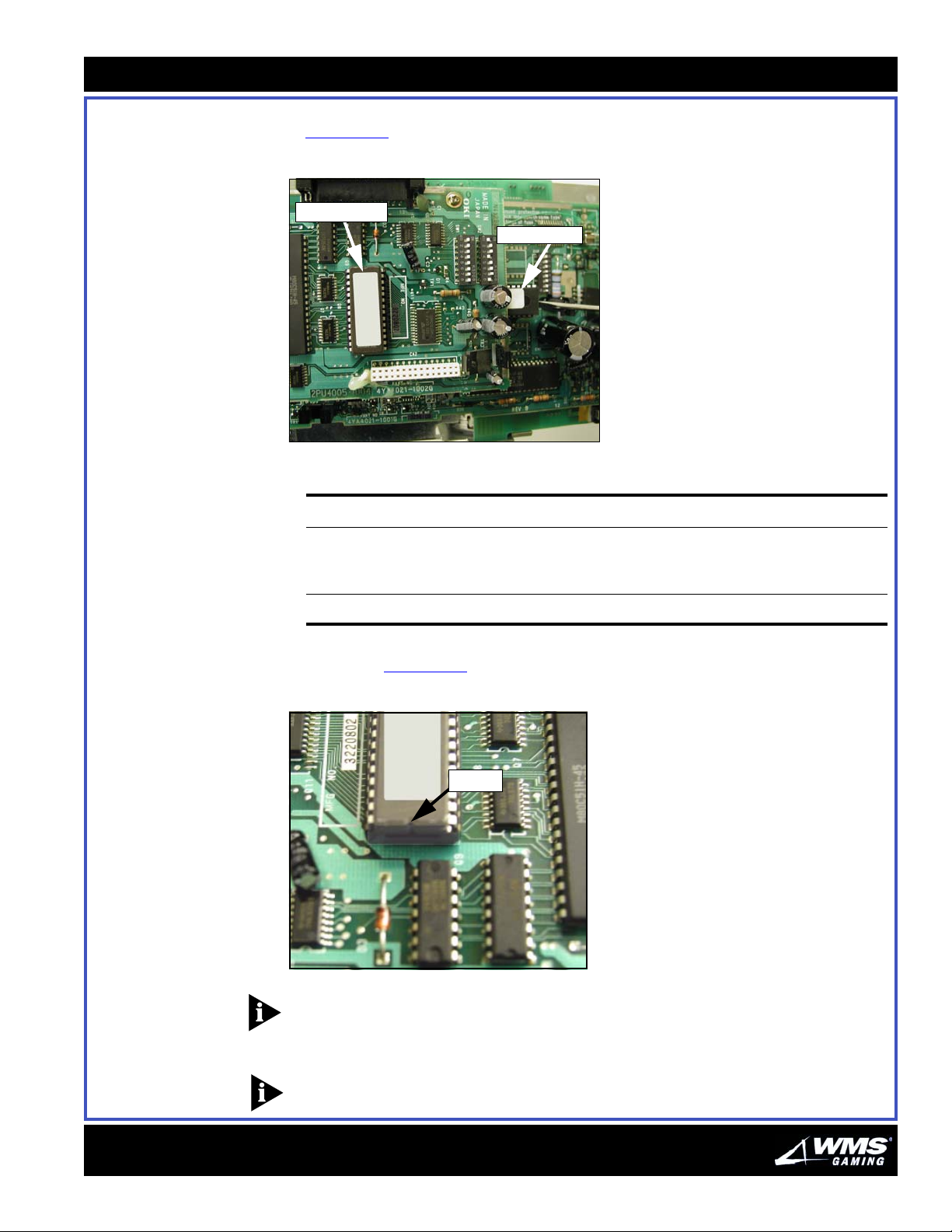
Chapte r 3: Mai ntenance
14 Turn the printer assembly over to access the Main and Serial EPROMs,
Figure 3-11
Figure 3-11 Printer EPROMs.
Serial EPROM
.
Main EPROM
15 Remove the firmware EPROM(s) requiring replacement as follows:
To remove... do the following:
3-31
the Main firmware EPROM using a small flathead screwdriver, carefully lift the EPROM
the Serial EPROM remove using standard chip-extraction tools
from the board socket without bending the EPROM leads;
the Main firmware EPROM may be accessed without
removing the top board
16 Insert the EPROM carefully by aligning the notch in the EPROM and the notch in
the board, Figure 3-12
Figure 3-12 EPROM notch.
.
notch
16-015714-00
NOTICE: Ensure that the notch on the EPROM is aligned correctly prior to pressing
down and seating the EPROM. Avoid bending the EPROM leads.
17 Return the printer assembly to the printer chassis.
NOTICE: The Main EPROM notch is covered by the top board.
Page 66
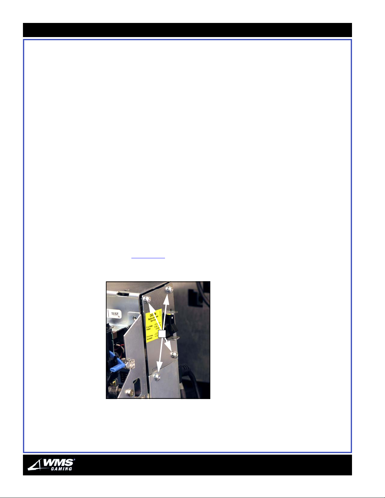
3-32
Printer
18 Reconnect the power supply cable.
19 Reconnect the data cable.
20 Replace the four captive Phillips screws to secure the printer assembly to the
chassis.
21 Lower the printer to its operational position.
22 To verify that the new printer firmware is recognized, hold the FEED | TEST button
to the left (FEED).
23 Power the printer back on. A Diagnostic ticket prints with the current versions of
Main and Serial firmware. Ensure that the printed information is accurate.
Replacing the Ithaca
70 Fuse
If the Ithaca 70 printer fails to power up, verify the following:
the power supply cable is connected securely at both ends
the VLT power is on, since the printer is powered via a switched outlet on the
PDU
If the printer still fails to power up, the fuse may need replacement. Complete the
following steps to replace the fuse:
1 Switch game power at the PDU to STANDBY.
2 Power the printer down at the printer power switch.
3 Lift the pull pin and slide the printer chassis out of the game.
4 Using a Phillips screwdriver, remove the four screws securing the power supply
cover, Figure 3-13
Figure 3-13 Four Phillips screws that allow
access to fuse.
(A).
A
5 Lift the power supply cover off the printer.
AUGUST 2005
Page 67
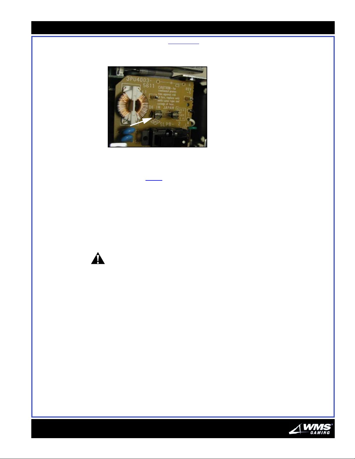
Chapte r 3: Mai ntenance
3-33
6 Pull the blown fuse, Figure 3-14, out of the clip towards you, and replace with the
1.0 A fuse (20-006623-05).
Figure 3-14 Printer fuse.
7 Verify that the fuse is fully seated in the clip.
8 Replace the power supply cover and secure with the four Phillips screws you
removed in step 4
.
9 Slide the printer chassis back into the game.
10 Power the game On at the PDU.
11 Power the printer On.
12 Verify that the printer is powering On.
Cleaning the Printer Periodically use a vacuum cleaner or air compressor to remove paper dust.
CAUTION: Never use alcohol or petroleum-based chemicals to clean the printer.
These cleaners damage plastic parts. The carriage rack is particularly sensitive.
These chemicals will ruin it. Avoid getting the cleaner on electronic components.
16-015714-00
Page 68
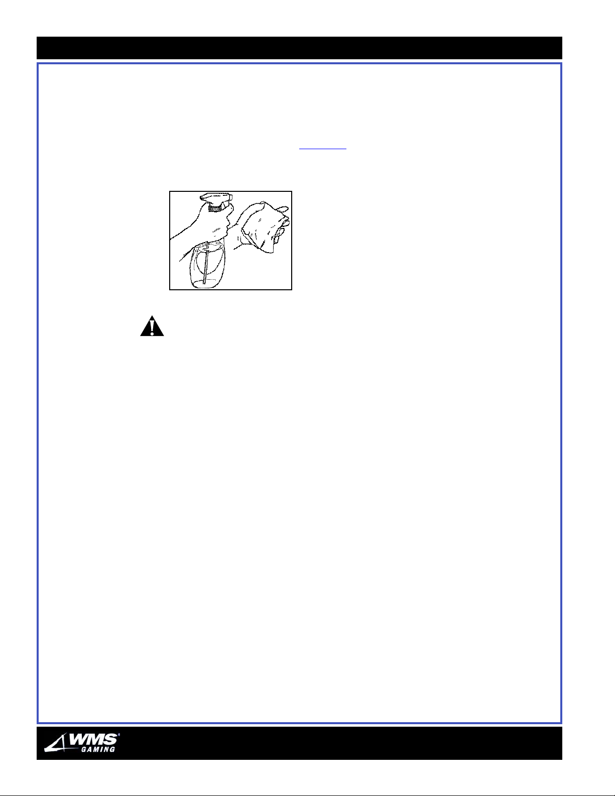
3-34
Touch Screen
Touch Screen This section provides information required to clean the Touch Screen.
Cleaning the Touch
Screen
Use a 99% alcohol cleaning solution to clean the Touch Screen. This type of
cleaning liquid evaporates rapidly and does not drip. You can use other alcoholbased cleaners, but never spray them directly on the screen. Instead, spray a cloth
and wipe the screen with it, Figure 3-1
Figure 3-1 Spray cloth and
wipe Touch Screen.
.
CAUTION: Never use abrasive cleansers or ammonia-based cleansers on the Touch
Screen.
AUGUST 2005
Page 69

AUGUST 2005
C
S
OFTWARE
HAPTER
A
4
DMINISTRATION
16-015715-00
Table of Contents ACCESSING THE SOFTWARE ADMINISTRATION MENUS ........................................................................... 4-2
The Key Switch..............................................................................................................................4-2
The Attendant Key.........................................................................................................................4-2
Buttons ..........................................................................................................................................4-3
Messages ......................................................................................................................................4-3
Field Features ...............................................................................................................................4-3
PERFORMING A RAM CLEAR .............................................................................................................. 4-5
SOFTWARE INSTALLATION ................................................................................................................... 4-6
ACCOUNTING MENU........................................................................................................................... 4-9
DIAGNOSTICS MENU ........................................................................................................................ 4-14
HISTORY MENU...............................................................................................................................4-28
SETUP MENU ..................................................................................................................................4-32
OUT OF SERVICE ............................................................................................................................. 4-47
Numeric Keypad............................................................................................................................4-4
Performing a RAM Clear...............................................................................................................4-6
Installing Software ........................................................................................................................4-7
Machine Accounting - Machine Master.......................................................................................4-9
Machine Accounting - Machine Period .................................................................................... 4-10
Game Accounting - Game Master............................................................................................. 4-10
Game Accounting - Game Period.............................................................................................. 4-11
Bill Accounting ........................................................................................................................... 4-12
Security Accounting ................................................................................................................... 4-13
Error Accounting ........................................................................................................................ 4-13
Version Information ................................................................................................................... 4-14
Jurisdiction Information Menu .................................................................................................. 4-15
Input/Output Diagnostics Menu ............................................................................................... 4-16
Cash Devices Diagnostics ......................................................................................................... 4-19
Video Diagnostics Menu ............................................................................................................ 4-23
Sound Diagnostics ..................................................................................................................... 4-26
Gtech Comm Status................................................................................................................... 4-27
Game Play .................................................................................................................................. 4-29
Event........................................................................................................................................... 4-29
Cash In History ........................................................................................................................... 4-31
Cash Out History ........................................................................................................................ 4-31
Security Events .......................................................................................................................... 4-32
Touch Screen ............................................................................................................................. 4-33
Sound ......................................................................................................................................... 4-37
Machine Setup ........................................................................................................................... 4-38
Device Setup .............................................................................................................................. 4-39
Bill Accept Setup ........................................................................................................................ 4-40
Game Settings............................................................................................................................ 4-40
Responsible Gaming ................................................................................................................. 4-43
Banner Setup ............................................................................................................................. 4-44
Paytable CRCs............................................................................................................................ 4-45
Gtech VLT Address ..................................................................................................................... 4-45
Page 70
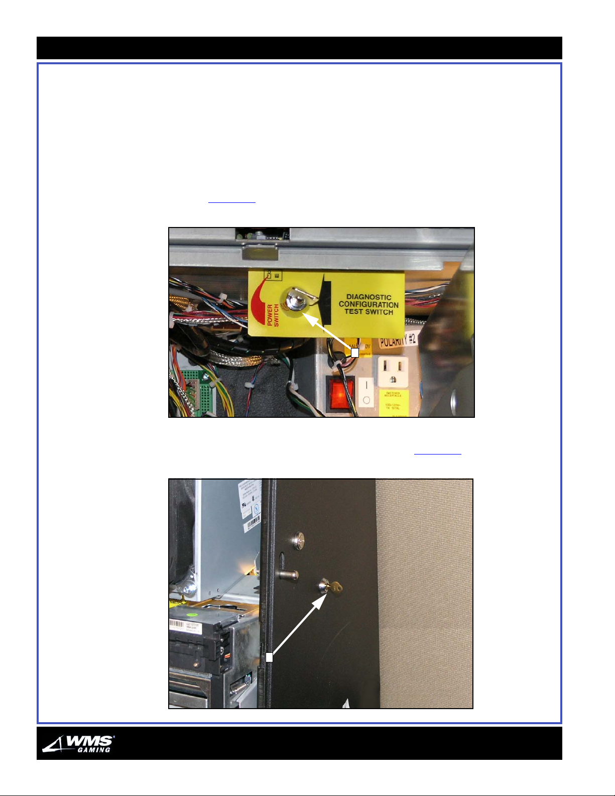
4-2
Accessing the Software Administration Menus
Accessing the
Software
Administration
Menus
The Key Switch The Key Switch is on the right side of the metal bar spanning the middle of the
Software administration menus are accessed by pressing the DIAGNOSTICS button
or turning the Attendant Key.
The Attendant Menu and Operator Menu are identical, except for the method of
accessing them and certain security restrictions preventing attendants from
accessing set-up functionality. For the purposes of this section, the menu will be
referred to as the Operator menu.
cabinet, Figure 4-1
Figure 4-1 Key Switch.
(A).
A
The Attendant Key The Attendant Key is on the right side of the cabinet, Figure 4-2 (A).
Figure 4-2 Attendant Key.
A
AUGUST 2005
Page 71
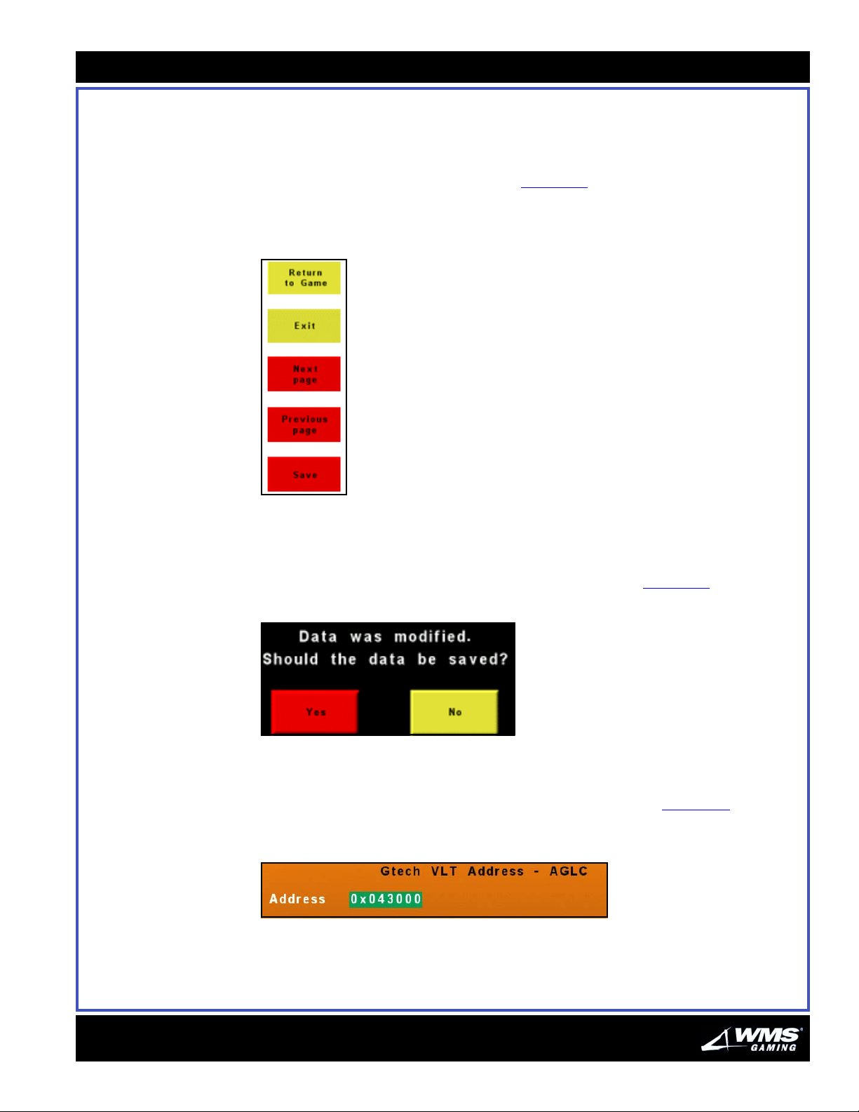
Chapter 4: Software Administration
4-3
The Attendant/Operator menus are navigated using the touch screen. There are
several buttons, messages, field and menu features:
Buttons
Common buttons display at the screen, Figure 4-3. These buttons are used to save
changed settings, view additional screens, exit from the current screen, and to
return the game to play.
Figure 4-3 Common buttons.
Messages
Messages often display at the bottom of the screen to notify you of important
information, including whether or not changes were saved, Figure 4-4
Figure 4-4 Message displays at bottom of screen.
.
Field Features
To set field values or to toggle a field, touch inside the field, Figure 4-5. Then, if a
numeric field needs to be entered, a keypad displays.
Figure 4-5 Sample field.
16-015715-00
Page 72
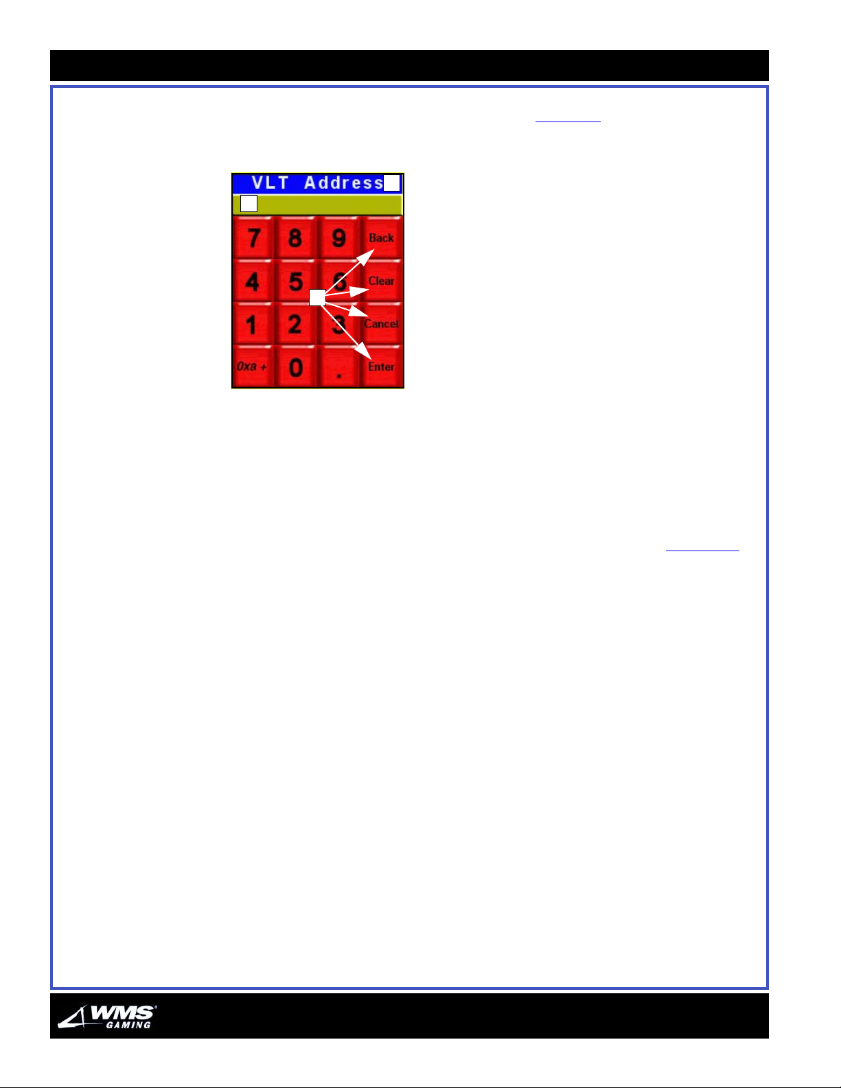
4-4
Accessing the Software Administration Menus
Numeric Keypad The numeric keypad includes a title (A), value entry area (B), a numeric keypad
similar to a calculator, and function buttons (C), Figure 4-6
.
Figure 4-6 Entering a value in the
numeric keypad.
A
B
C
These buttons accomplish the following:
Back: Erases entry one digit at a time
Clear: Clears all digits
Cancel: Closes the keypad with no entry or change
Enter: Saves the entry
The button labeled Oxa + lets you set all the hex values required for the VLT
Address. This function is explained in the Gtech VLT Address screen, Figure 4-85
.
AUGUST 2005
Page 73
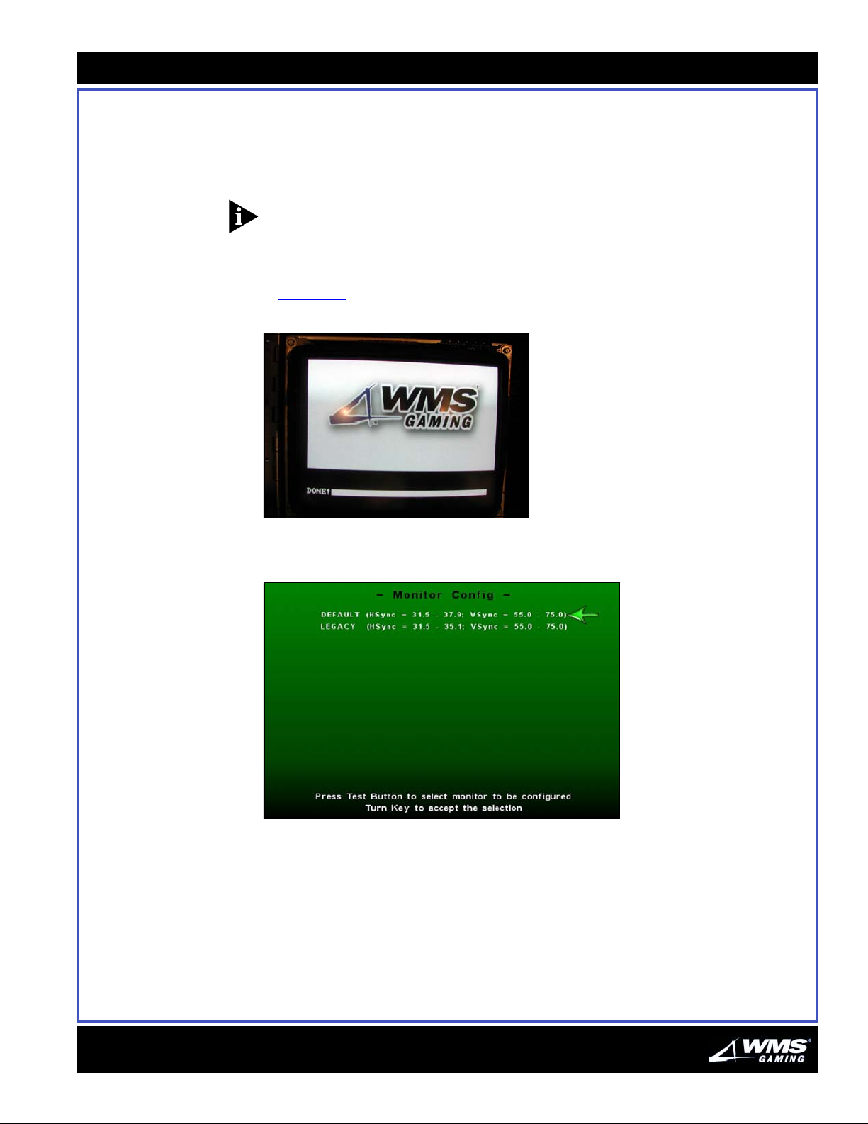
Chapter 4: Software Administration
4-5
Performing a RAM Clear
Follow the steps below to perform a RAM clear.
1 Insert the RAM Clear CompactFlash card into the OS flash drive on the CPU. Use
the direction indicator on the CompactFlash card to ensure proper insertion.
Ensure the RAM Clear version matches that of the OS CompactFlash version.
NOTICE: This process may take several minutes.
2 Turn the game power to On. The game boots and a progress indicator with the
WMS Gaming Inc. logo displays while the RAM Clear process initializes,
Figure 4-7
Figure 4-7 Game initialization screen.
.
3 Once the game is booted, the Monitor Config screen displays, Figure 4-8.
Figure 4-8 Monitor Config screen.
16-015715-00
Page 74
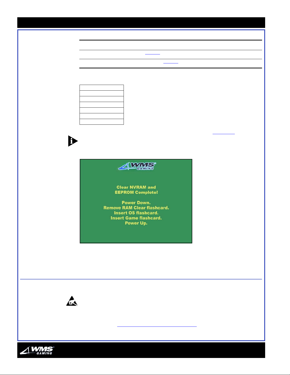
4-6
Software Installation
4 Determine the following:
If your VLT... then...
has one of the Legacy monitors listed in Table 4-1 select the LEGACY option
does NOT have one of the Legacy monitors listed in Table 4-1 select the DEFAULT option
Table 4-1 Legacy Monitors (Wells-Gardner).
WGT1730-S1DS78G
WGT1730-S1DS71H
WGT1930-M1TS14E
WGT1930-S5TS48H
WGT1930-S5TS10J
WGT1930-S5TS21K
WGT1930-S5TS39F
5 Turn the Attendant Key. The VLT reboots and the screen in Figure 4-9 displays.
NOTICE: The reboot process may take several minutes.
Figure 4-9 Clear NVRAM and EEPROM Complete screen.
Software
Installation
Performing a RAM
Clear
6 Power the VLT Off.
7 Remove the RAM Clear CompactFlash card.
This section provides the procedures required to install game software.
ESD: Ensure that proper ESD practices are followed. See the About This Guide
chapter of this document for the ESD procedure.
Before installing game software, a RAM clear must be performed. Follow the steps
in the procedure “
Performing a RAM Clear” on page 5 before installing software.
AUGUST 2005
Page 75
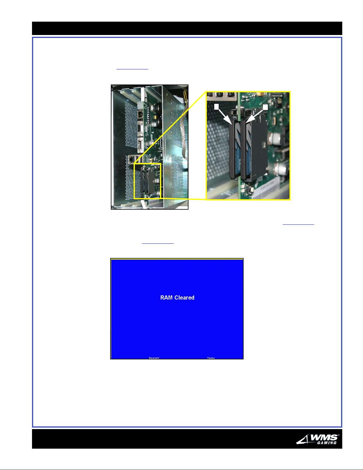
Chapter 4: Software Administration
Installing Software Perform the steps in this section to install software for the game.
1 Install the operating system (OS) CompactFlash card in the OS flash drive,
Figure 4-10
Figure 4-10 CompactFlash drives.
.
(A).
4-7
A
B
2 Install the game CompactFlash card in the game flash drive, Figure 4-10 (B).
3 Power the game On. After the VLT has powered up, the RAM Cleared screen
displays, Figure 4-11
Figure 4-11 Ram Cleared screen.
.
16-015715-00
4 Open the Main Door.
Page 76
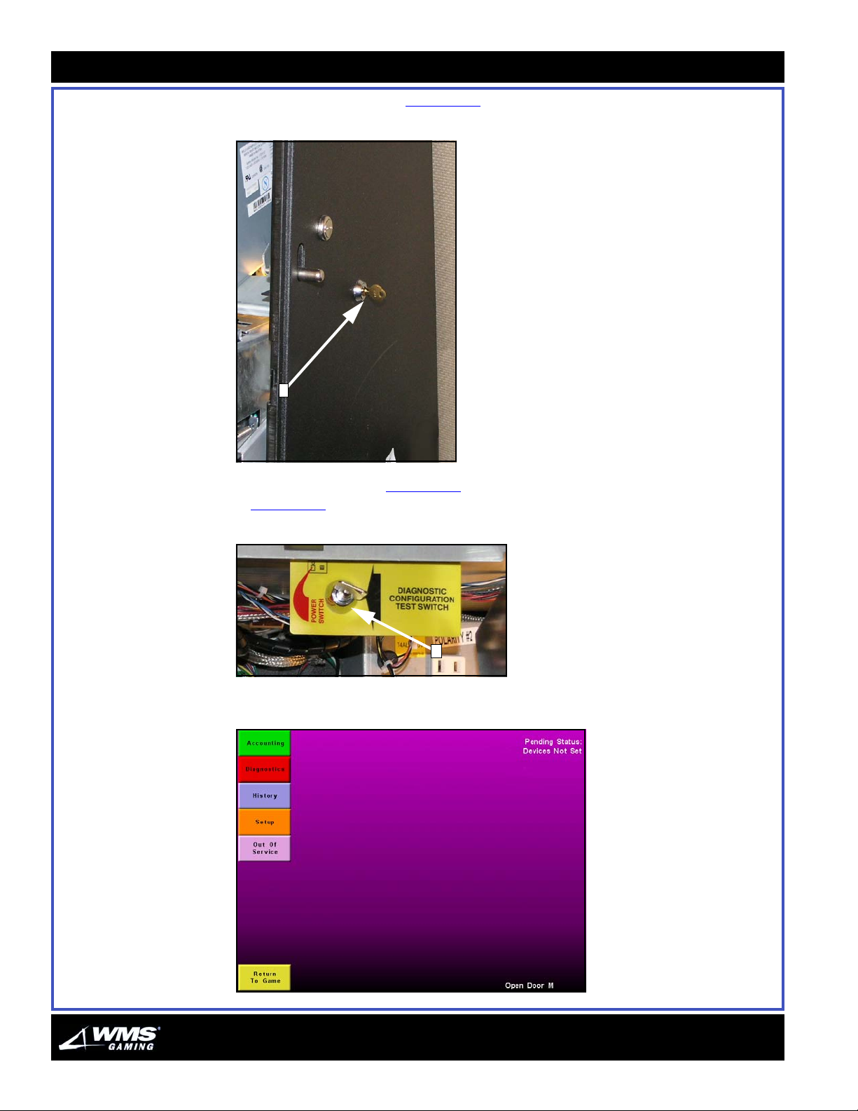
4-8
Software Installation
5 Turn the Attendant Key, Figure 4-12 (A).
Figure 4-12 Attendant Key.
A
6 Turn the Key Switch, Figure 4-13 (A). The Administration Menu displays,
Figure 4-14
Figure 4-13 Key Switch.
Figure 4-14 Administration Menu.
.
A
AUGUST 2005
Page 77
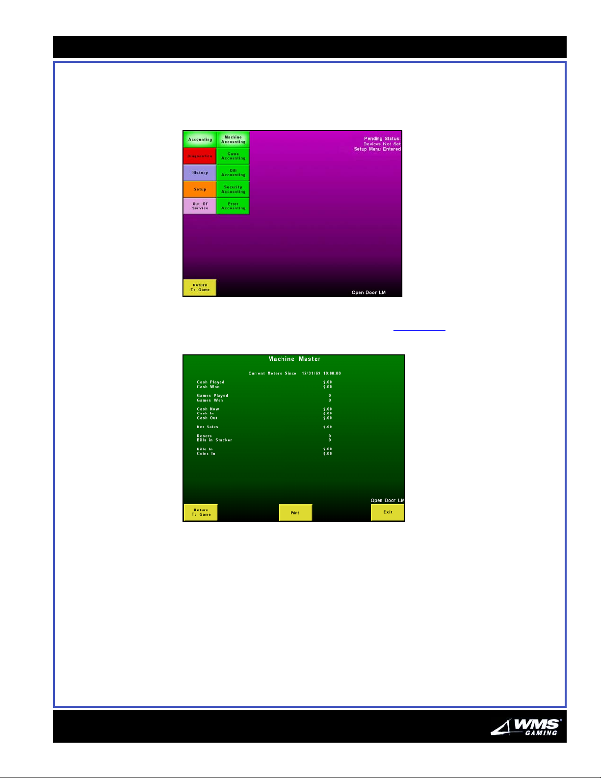
Chapter 4: Software Administration
4-9
Accounting Menu The Accounting Menu (with identical functionality for both Operator and Attendant)
contains submenus (shown below) most of which are for viewing purposes only. The
data involves statistics about the machine and games completed.
Figure 4-15 Accounting Menu.
Machine Accounting -
Machine Master
From the Operator Menu, select Accounting, then Machine Accounting, then
Machine Master to view all meter information, Figure 4-16
Figure 4-16 Machine Master screen.
.
16-015715-00
Page 78

4-10
Accounting Menu
Machine Accounting -
Machine Period
Game Accounting -
Game Master
From the Operator Menu, select Accounting, then Machine Accounting then
Machine Period to view meter information since period meters were last cleared,
Figure 4-17
Figure 4-17 Machine Period screen.
.
From the Operator Menu, select Accounting, then Game Accounting, then Game
Master to view meter information, Figure 4-18
. If more than one Game is available,
the Previous Game ID and Next Game ID buttons display, allowing you to switch to
the other available games.
Figure 4-18 Game Master screen.
AUGUST 2005
Page 79
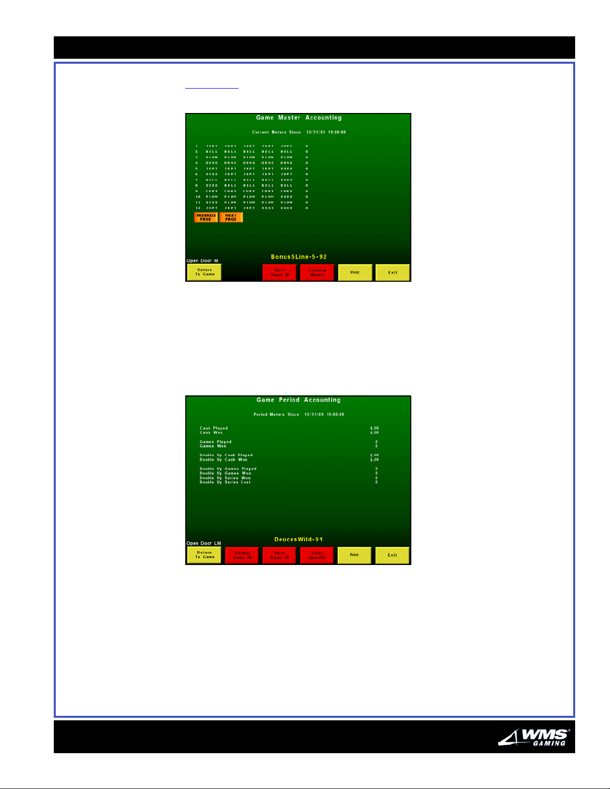
Chapter 4: Software Administration
4-11
The Game Specific button shows you detailed accounting data on the chosen game,
Figure 4-19
Figure 4-19 Game Specific Game Master screen.
.
Game Accounting -
Game Period
From the Operator Menu, select Accounting, then Game Accounting, then Game
Period to view meter information since period meters were last cleared.
If more than one Game is available, the Previous Game ID and Next Game ID
buttons display, allowing you to switch to the other available games.
Figure 4-20 Game Period Accounting screen.
16-015715-00
Page 80
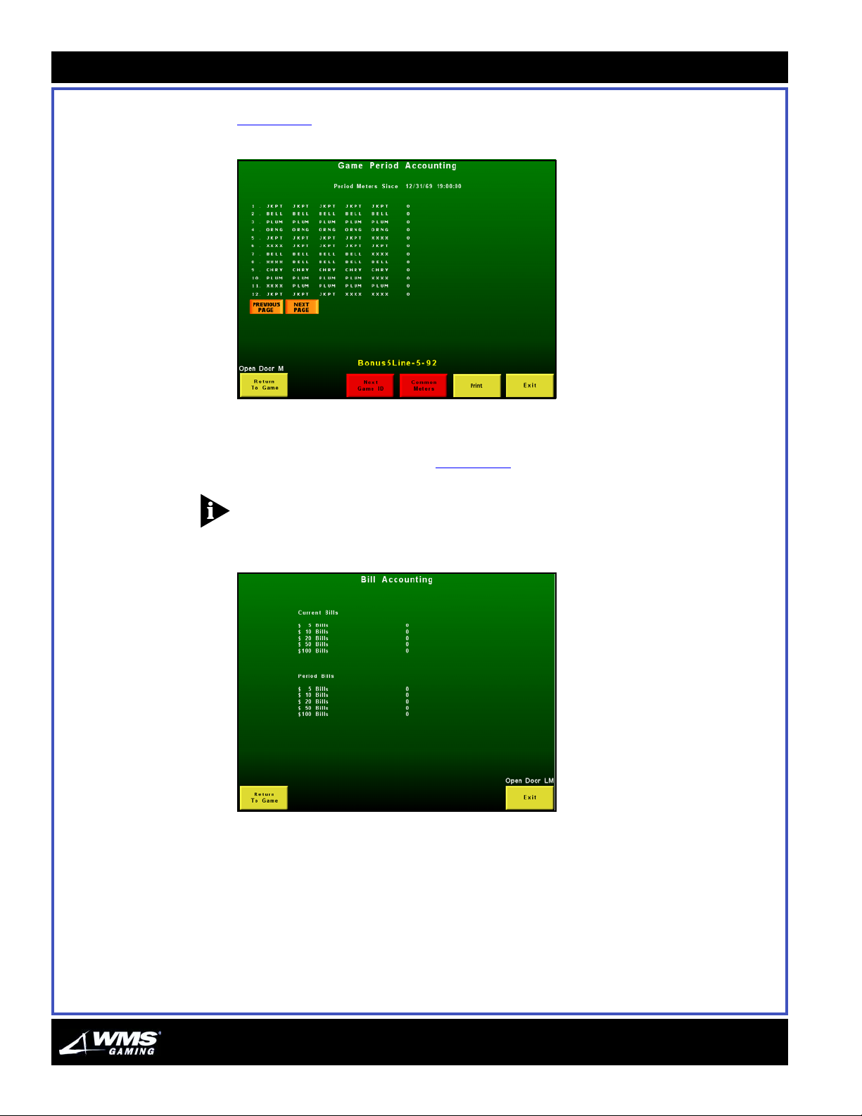
4-12
Accounting Menu
The Game Specific button shows you detailed data on the chosen game,
Figure 4-21
Figure 4-21 Game Specific Game Period screen.
.
Bill Accounting From the Operator Menu, select Accounting, then Bill Accounting to view all master
and period meter information, Figure 4-22
.
NOTICE: To print Bill Accounting information, select Print from the Machine Master
screen. The Current Bills and Period Bills will be included on the printout.
Figure 4-22 Bill Accounting screen.
AUGUST 2005
Page 81
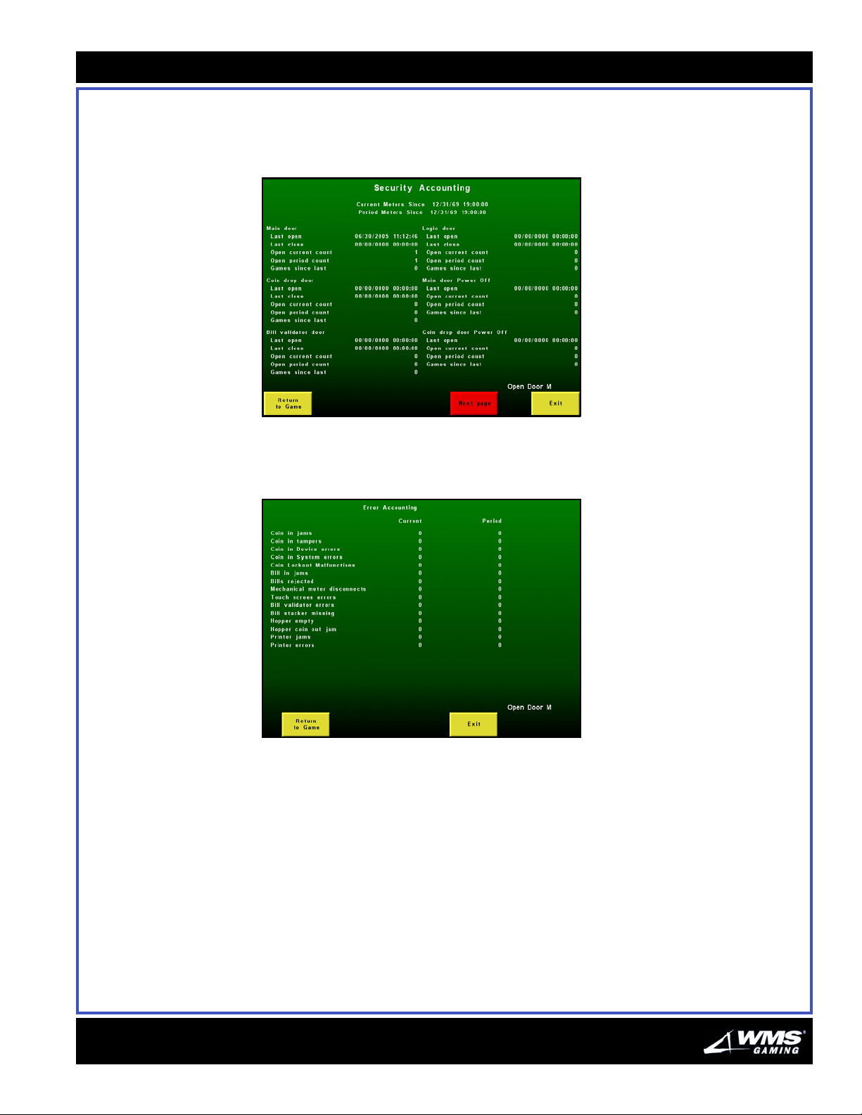
Chapter 4: Software Administration
4-13
Security Accounting From the Operator Menu, select Accounting, then Security Accounting to view
security meters involving such data as last power failure (date and time), door open,
and total games played.
Figure 4-23 Security Accounting screen.
Error Accounting From the Operator Menu screen, select Accounting, then Error Accounting to view
error accounting meters.
Figure 4-24 Error Accounting screen.
16-015715-00
Page 82
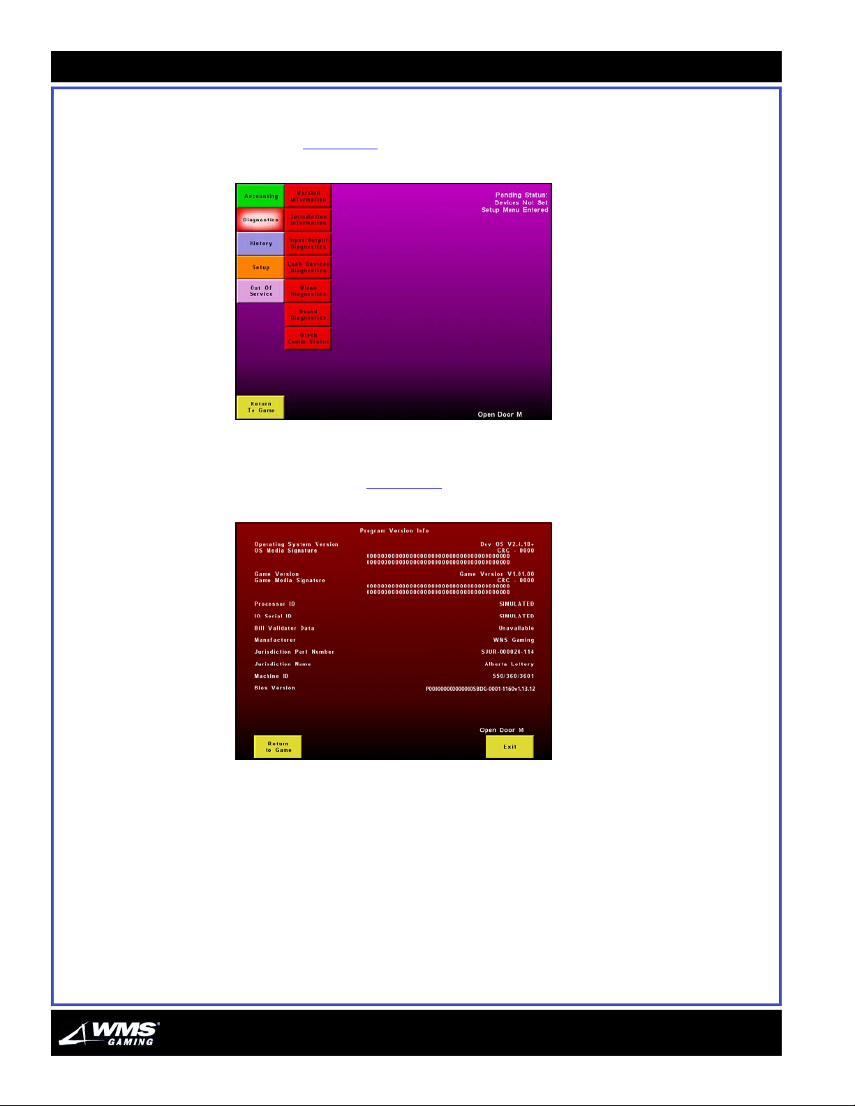
4-14
Diagnostics Menu
Diagnostics Menu Diagnostics involve testing the status of a machine and system components either
for regular maintenance purposes to verify functionality or to troubleshoot specific
problems, Figure 4-25
Figure 4-25 Diagnostics Menu.
Version Information Selecting Version Information from the Diagnostics Menu displays the Program
Version Info screen, Figure 4-26
.
.
Figure 4-26 Program Version Info screen.
AUGUST 2005
Page 83
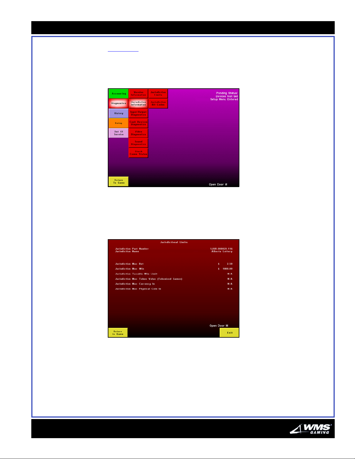
Chapter 4: Software Administration
4-15
Jurisdiction
Information Menu
Selecting Jurisdiction Information from the Diagnostics Menu displays two options,
Figure 4-27
Jurisdiction Limits
Jurisdiction Bit Codes
Figure 4-27 Jurisdiction Information Menu options.
:
Jurisdiction Limit
From the Jurisdiction Information screen, select Jurisdiction Limits. The
Jurisdictional Limits screen displays:
Figure 4-28 Jurisdictional Limits screen.
16-015715-00
Page 84
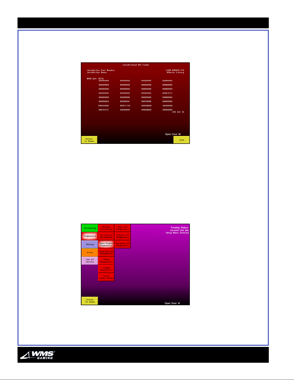
4-16
Diagnostics Menu
Jurisdiction Bit Codes
From the Jurisdiction Information screen, select the Jurisdiction Bit Codes button.
The Jurisdictional Bit Codes screen displays:
Figure 4-29 Jurisdictional Bit Codes screen.
The screen displays any undefined options in yellow. Select the Return to Game
button to return or Exit to go back to the menu.
Input/Output
Diagnostics Menu
Select Diagnostics, then Input/Output Diagnostics.
The Input/Output Diagnostics are further divided into three I/O submenus:
Door
Cabinet
Processor
Figure 4-30 Input/Output Diagnostics button.
AUGUST 2005
Page 85
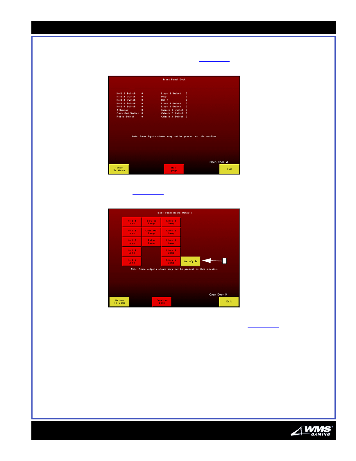
Chapter 4: Software Administration
4-17
Door I/O
Select Door I/O Diagnostics. The Door I/O screen displays. Switch settings for
various features: on (1) or off (0), Figure 4-31
Figure 4-31 Door I/O screen.
.
Clicking Next page brings you to a screen that lets you choose the Front Panel Board
Outputs, Figure 4-32
Figure 4-32 Front Panel Board Outputs.
A
Test each individual mechanism by selecting its button, or automatically cycle
through them all by selecting the Auto Cycle button, Figure 4-32
(A).
16-015715-00
Page 86
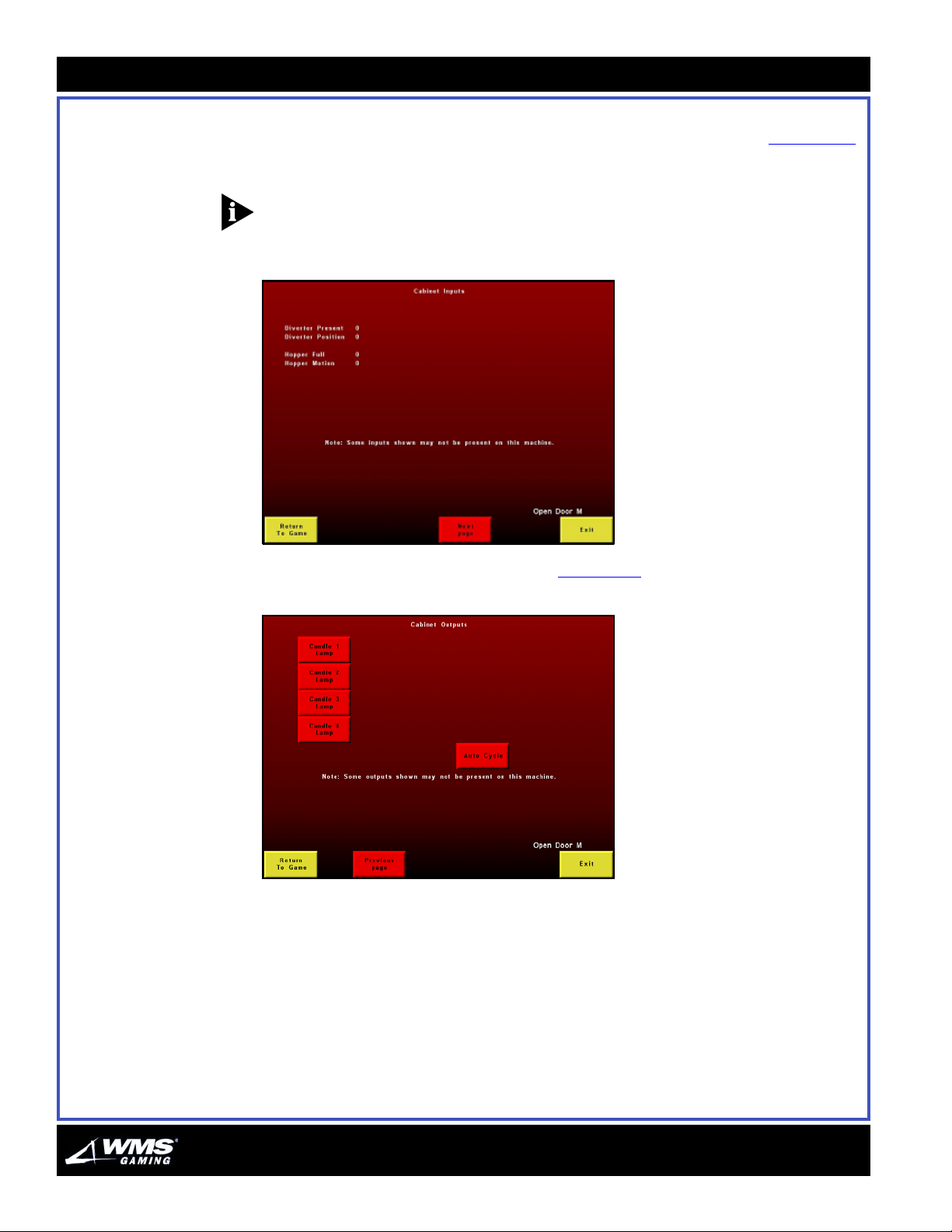
4-18
Diagnostics Menu
Cabinet I/O
Select Cabinet I/O Diagnostics. The Cabinet Inputs screen displays, Figure 4-33.
Switch settings on (1) or off (0) for the mechanisms indicated on the screen.
NOTICE: Since there is no Hopper in the gaming device, the Hopper data will always
be set to zero.
Figure 4-33 Cabinet Inputs screen.
Select Next Page to display the screen in Figure 4-34.
Figure 4-34 Cabinet Outputs screen.
AUGUST 2005
Page 87
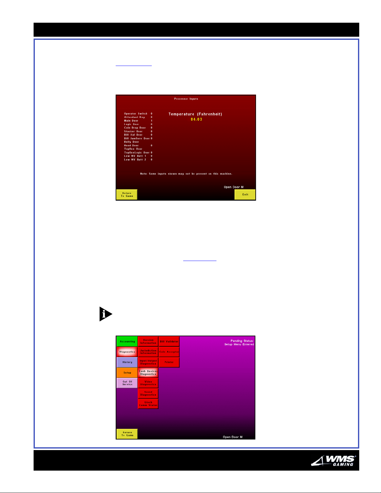
Chapter 4: Software Administration
Processor I/O
Select Processor I/O Diagnostics. The Processor I/O Diagnostics screen,
Figure 4-35
, displays. This screen presents the settings for processor-related
functions: on (1) or off (0), as well as the Processor temperature.
Figure 4-35 Image Processor Inputs screen.
4-19
Cash Devices
Diagnostics
With the game operating at room temperature, 68-73°F (20-23°C), the processor
temperature will typically not exceed 129° F (54° C). If the temperature reading on
the Processor Inputs screen exceeds this value, verify the following:
The processor fan and CPU enclosure fan are operating normally.
The CPU enclosure and game cabinet vents are not obstructed.
The Diagnostics Menu, Figure 4-36, includes a Cash Devices option, which allows
you to perform the following tests:
Bill Validator Test (for tickets and vouchers)
Coin Acceptor
Printer Test (printing a void voucher)
NOTICE: Before initiating any Cash Devices tests, ensure that the devices are
correctly set. To set the device, select Device Setup from the Machine Setup screen.
Figure 4-36 Cash Diagnostics Menu.
16-015715-00
Page 88
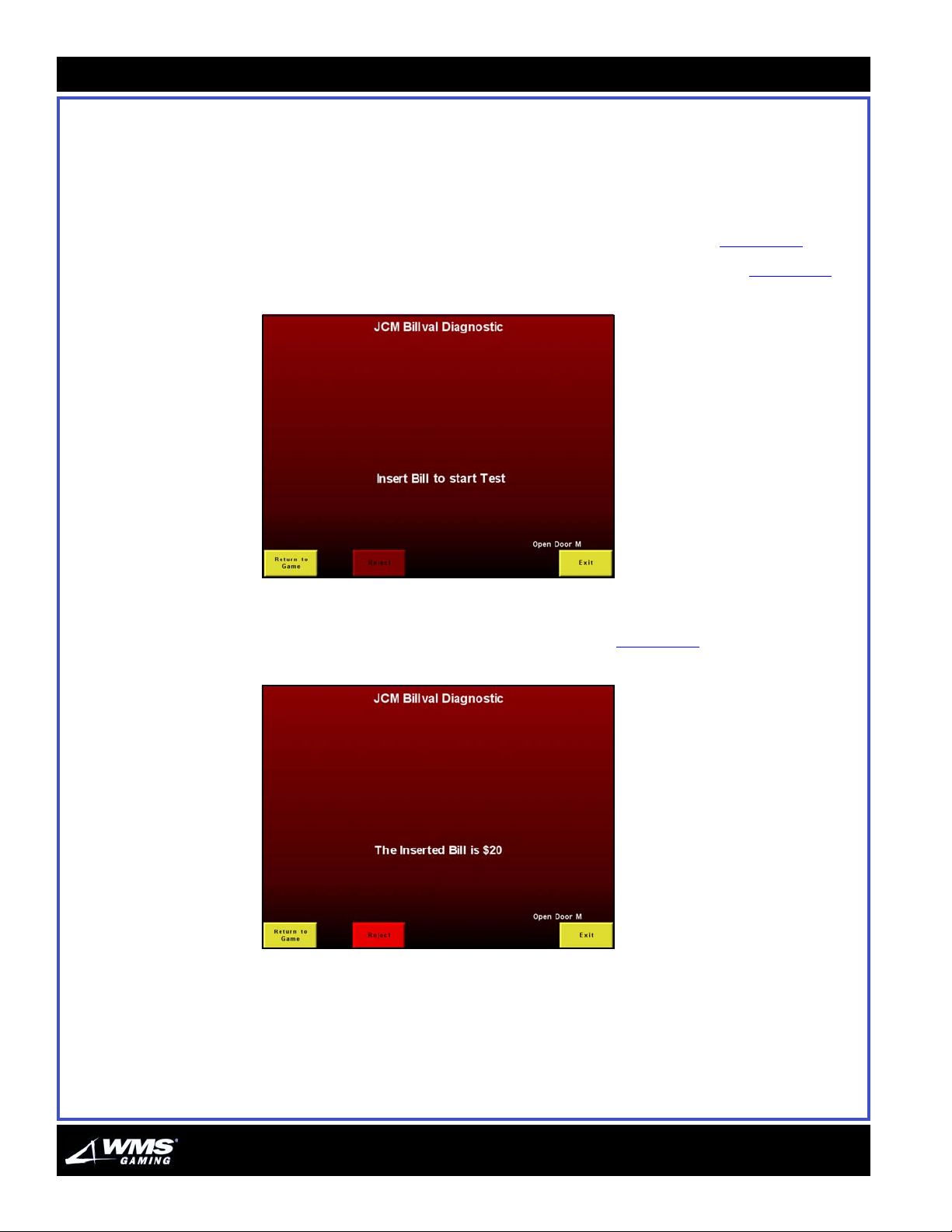
4-20
Diagnostics Menu
Bill Validator Test
Complete the following steps to initiate a Bill Validator Test:
1 Open the Main Door.
2 Turn the Key Switch.
3 Select Cash Devices Diagnostics from the Diagnostics Menu, Figure 4-36
.
4 Select Bill Validator. The Bill Validator Diagnostic screen displays, Figure 4-37
Figure 4-37 JCM Billval Diagnostic screen.
5 Insert a valid bill.
6 A message displays regarding the inserted bill, Figure 4-38
Figure 4-38 JCM Billval Diagnostic screen (bill).
.
.
AUGUST 2005
Page 89
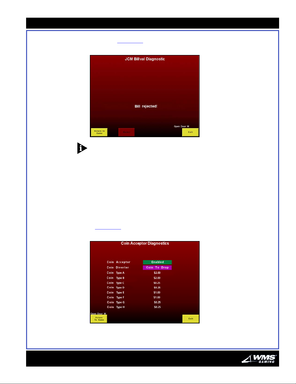
Chapter 4: Software Administration
4-21
7 Select Reject to return the bill. A message displays to confirm the successful
rejection, Figure 4-39
Figure 4-39 JCM Billval Diagnostic screen.
.
NOTICE: After a time-out period, the Bill Validator rejects the bill or voucher
automatically.
8 Press Exit or Return to Game.
Coin Acceptor
Complete the following steps to test the Coin Acceptor:
1 Open the Main Door.
2 Turn the Key Switch.
3 Select Cash Devices Diagnostics from the Diagnostics Menu.
4 Select Coin Acceptor. The Coin Acceptor Diagnostics screen displays,
Figure 4-40
Figure 4-40 Enabled Coin Acceptor “Coin to Drop” screen.
.
16-015715-00
5 The Coin Acceptor field lets you choose between two options: Enabled and
Disabled. Ensure that this field is always set to Enabled.
Page 90
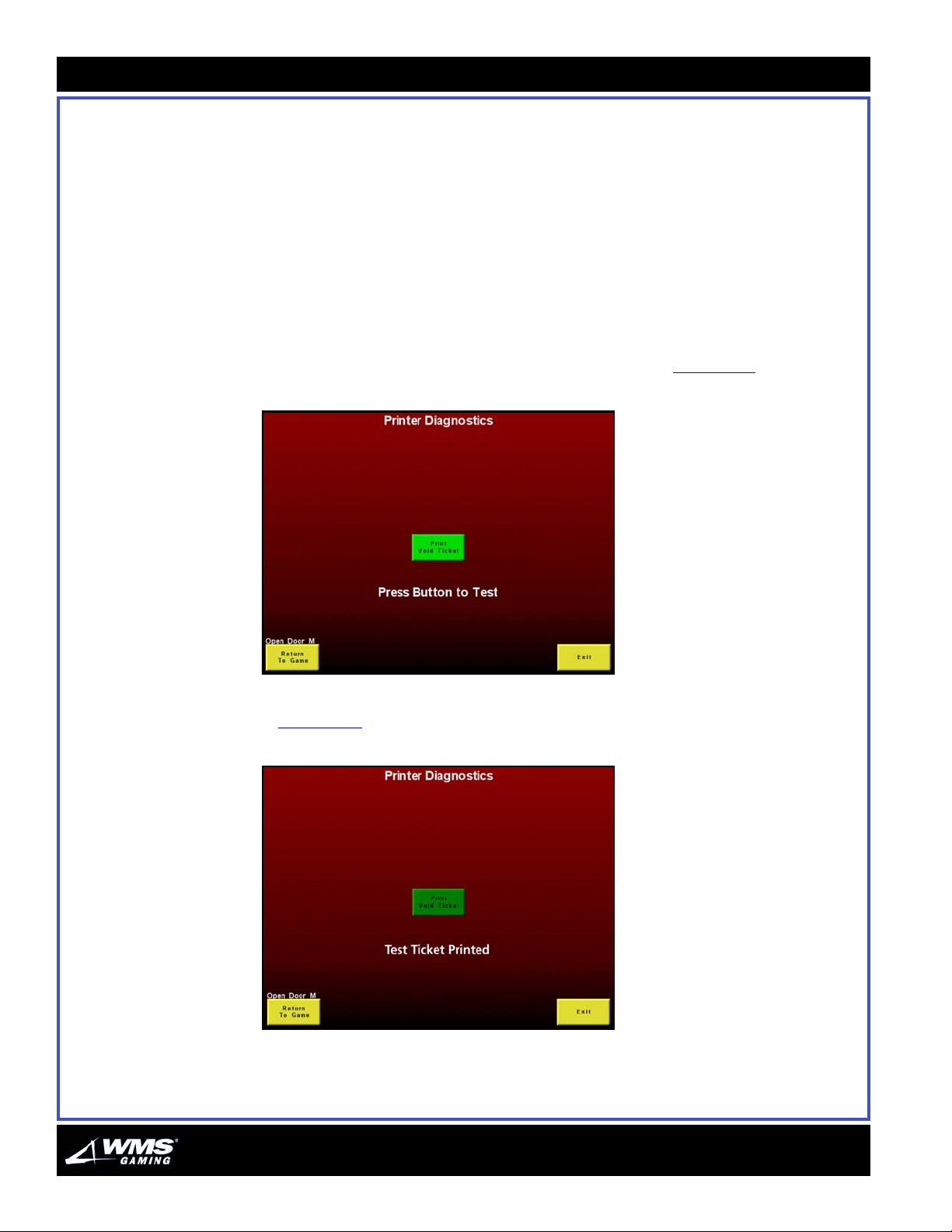
4-22
Diagnostics Menu
6 The Coin Diverter field lets you choose between two options: Coin to Hopper and
Coin to Drop. Since there is no hopper in the VLT, ensure that this field is always
set to Coin to Drop.
7 Select Exit.
Printer Diagnostics
Complete the following steps to test the Printer:
1 Open the Main Door.
2 Turn the Key Switch.
3 Select Cash Devices Diagnostics from the Diagnostics Menu.
4 Select Printer. The Printer Diagnostics screen displays, Figure 4-41
Figure 4-41 Printer Diagnostics screen.
.
5 Select Print Void Ticket. A ticket prints, displaying a message on the screen,
Figure 4-42
Figure 4-42 Printer Diagnostics screen.
.
6 Verify that a ticket was printed.
7 Select Exit once the test is complete.
AUGUST 2005
Page 91

Chapter 4: Software Administration
4-23
Video Diagnostics
Menu
The Video Diagnostics submenus, Figure 4-43, are used to check the purity of color
and verify screen alignment. If there is a problem with the color or alignment, adjust
the monitor to obtain the correct effect. Refer to your monitor documentation.
NOTE: These options are for monitor adjustments. Calibration options, located in
the Setup Menu, are for touch screen adjustments.
Figure 4-43 Video Diagnostics Menu.
Color Purity
The Color Purity screens, Figure 4-44 through Figure 4-46, test the video gun. The
entire screen should appear solid red, green, or blue, with uniform color.
Figure 4-44 Red Purity screen.
16-015715-00
Page 92
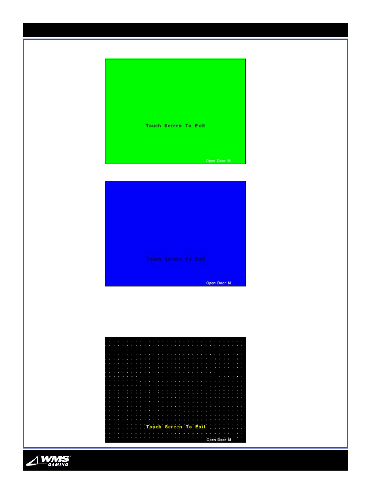
4-24
Diagnostics Menu
Figure 4-45 Green Purity screen.
Figure 4-46 Blue Purity screen.
Report any variation to a factory-authorized technician.
Dot Alignment
View the dot (pixel) alignment, Figure 4-47, and verify the spacing is regular.
Figure 4-47 Dot Alignment screen.
AUGUST 2005
Page 93
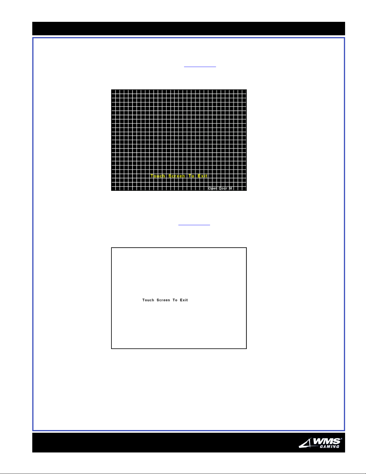
Chapter 4: Software Administration
4-25
Report any variation to a factory-authorized technician.
Graph Alignment
View the graph alignment, Figure 4-48, and verify the lines are straight and regularly
spaced.
Figure 4-48 Graph Alignment screen.
Report any variation to a factory-authorized technician.
White Temp
The White Temp screen, Figure 4-49, is the final test. A completely white screen with
no color tint indicates a successful test.
Figure 4-49 White Temp screen.
Report any variation to a factory-authorized technician.
16-015715-00
Page 94
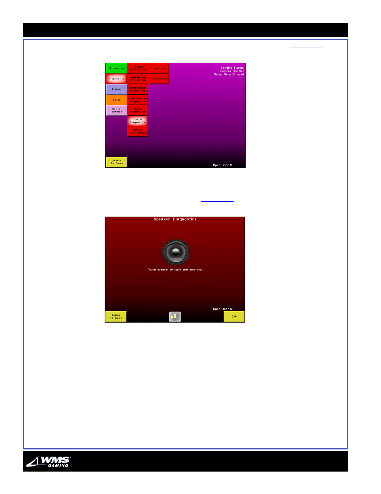
4-26
Diagnostics Menu
Sound Diagnostics The Sound Diagnostics let you calibrate the sound on the game, Figure 4-50.
Figure 4-50 Sound Diagnostics menu.
Sound Diagnostics - Speakers
The Speaker Diagnostics screen, Figure 4-51, lets you test the speakers.
Figure 4-51 Speaker Diagnostics menu.
AUGUST 2005
Page 95
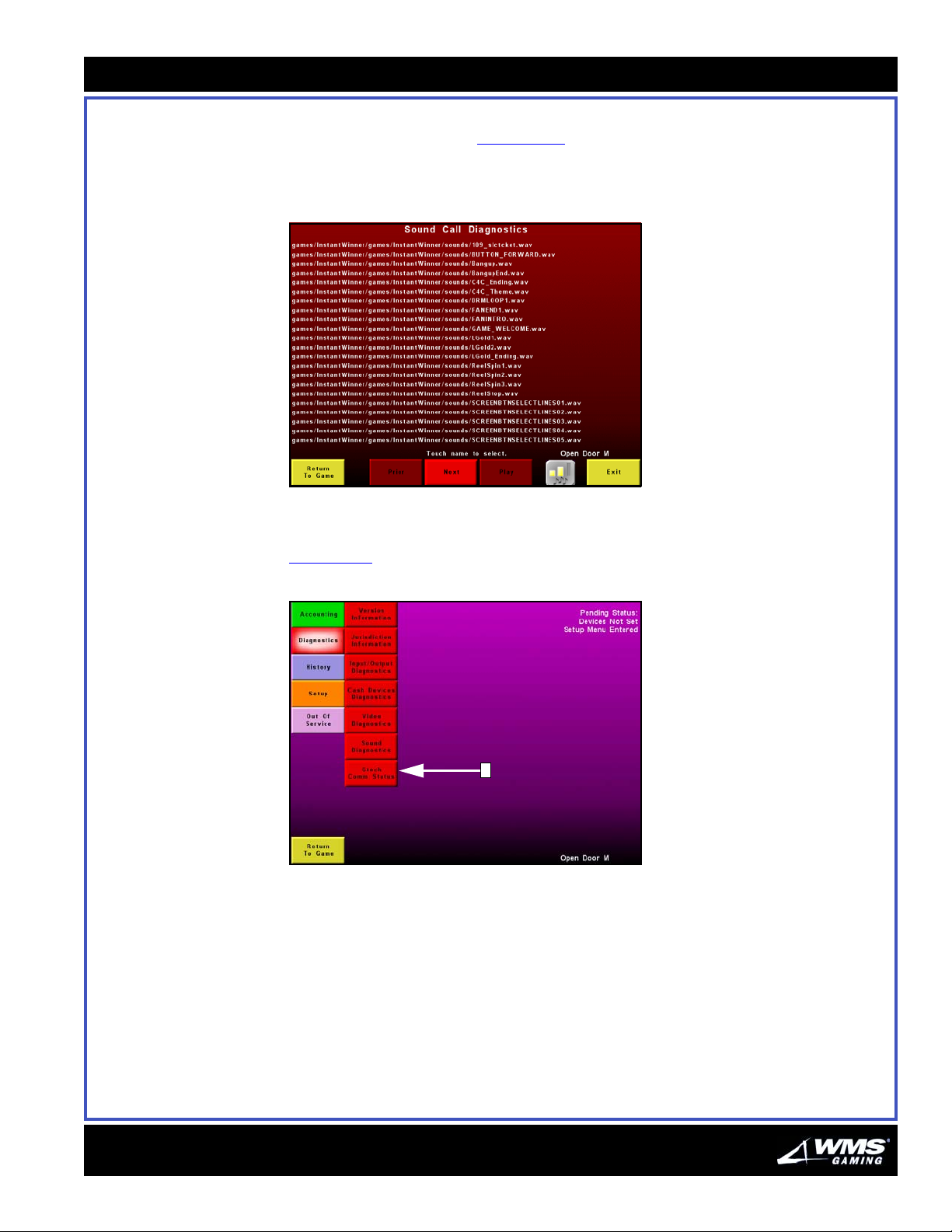
Chapter 4: Software Administration
4-27
Sound Diagnostics - Sound Calls
The Sound Calls screen, Figure 4-52, lets you test the various sounds that play
throughout the game. Highlight one or more of the sounds listed in the screen and
click Play.
Figure 4-52 Sound Calls screen.
Gtech Comm Status The Gtech Comm Status screen is accessed from the Diagnostics Menu,
Figure 4-53
Figure 4-53 Gtech Comm Status in Diagnostics Menu.
(A).
A
16-015715-00
Page 96
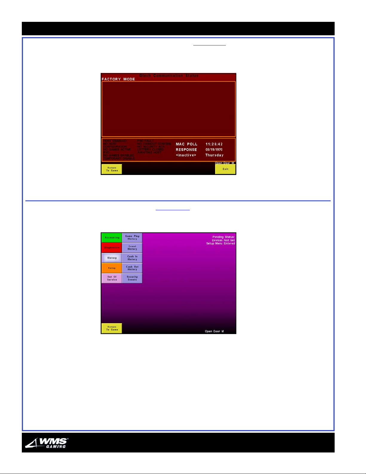
4-28
History Menu
The Gtech Comm Status screen, Figure 4-54, lets you see communications taking
place between the game and the host system.
Figure 4-54 Gtech Comm Status screen.
History Menu The History Menu, Figure 4-55, provides access to logs of important game and
machine-related information.
Figure 4-55 History Menu.
AUGUST 2005
Page 97
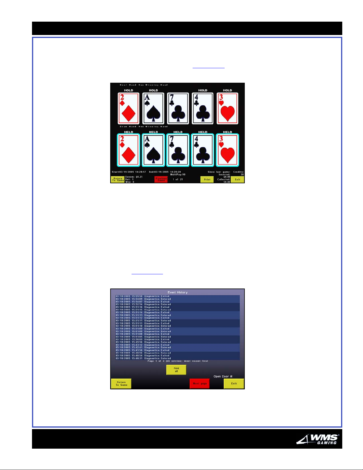
Chapter 4: Software Administration
4-29
Game Play Use the Game Play History option to display snapshot screens of the hundred most
recently played games in the order in which they were played. This valuable feature
is used to verify the outcome of a game to resolve disputes. Note that statistics are
shown in white at the bottom, Figure 4-56
Figure 4-56 Game Play History screen.
.
Use the Previous Game/Next Game buttons respectively to move to the previous or
next game.
Event An event is a specific action of input or output coming to or from a component
within the system. Event logs are particularly useful for troubleshooting problems
occurring on a game. Some events are routine status reports about something you
probably know, such as “Main Door Open”, and others are procedural or security
related, such as “Setup Menu Entered”. Other types of events report error
conditions that prevent game play, such as “No Comm Event: Out of Service No
Host 202”. The event history log is a chronological listing of the machine's last 500
events, Figure 4-57
Figure 4-57 Event History screen.
.
16-015715-00
Page 98
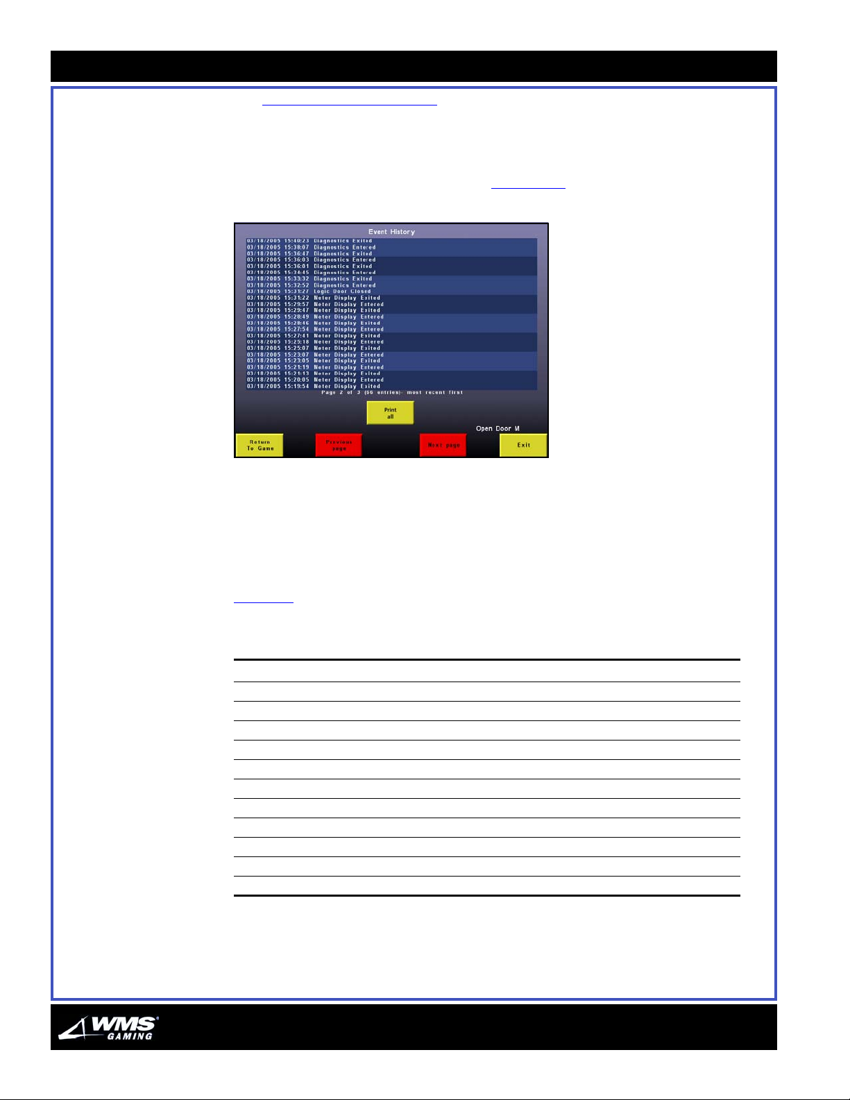
4-30
History Menu
See “List of Events” on page 30 for a complete list of events.
1 Select the Previous Page/Next Page function. Use the buttons respectively to
advance to the previous or next game.
2 Select Next Page to see more events, Figure 4-58
Figure 4-58 Second Event History screen.
.
3 Select Exit to return to the Operator Menu.
4 Select Return to Game to resume game play.
5 Select Previous Page to return to the previous screen.
List of Events
Tabl e 4-2 provides a complete list of events.
Table 4-2 List of Events.
Events
Attendant Menu Entered Coin Acceptor Tamper Logic Door Closed
Attendant Menu Exited Coin Acceptor Tamper Cleared Logic Door Open
Bill Rejected Date/Time Not Set Main Door Closed
Bill Rejection Limit Exceeded Date/Time Set Main Door Open
BillVal Acceptor Jam Denomination Not Set Memory Check Passed
BillVal Acceptor Jam Cleared Denomination Set Meter Display Entered
BillVal Com Error Devices Not Set Meter Display Exited
BillVal Com Error Cleared Devices Set Nvram Battery Low
BillVal Device Error Diagnostics Entered Nvram Battery Ok
BillVal Device Error Cleared Diagnostics Exited Pay Win Hand Pay Cleared
BillVal Door Closed End of Game Pay Win Hand Pay Lockup
AUGUST 2005
Page 99
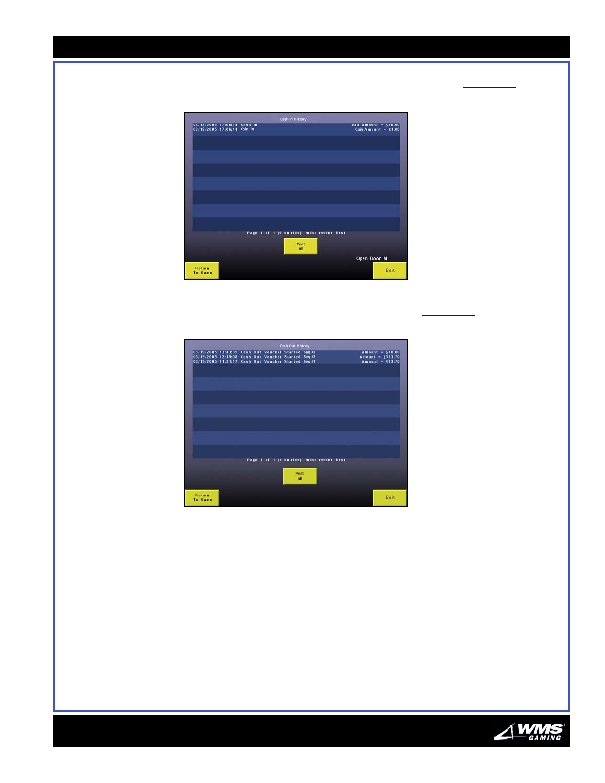
Chapter 4: Software Administration
4-31
Cash In History Each time-stamped line shows the total money taken in by the bill acceptor or coin
mechanism. Cash In events are used as the basis of this log, Figure 4-59
Figure 4-59 Cash In History log screen.
.
Cash Out History Shows all the Cash Out tickets that were generated, Figure 4-60.
Figure 4-60 Cash Out History screen.
16-015715-00
Page 100
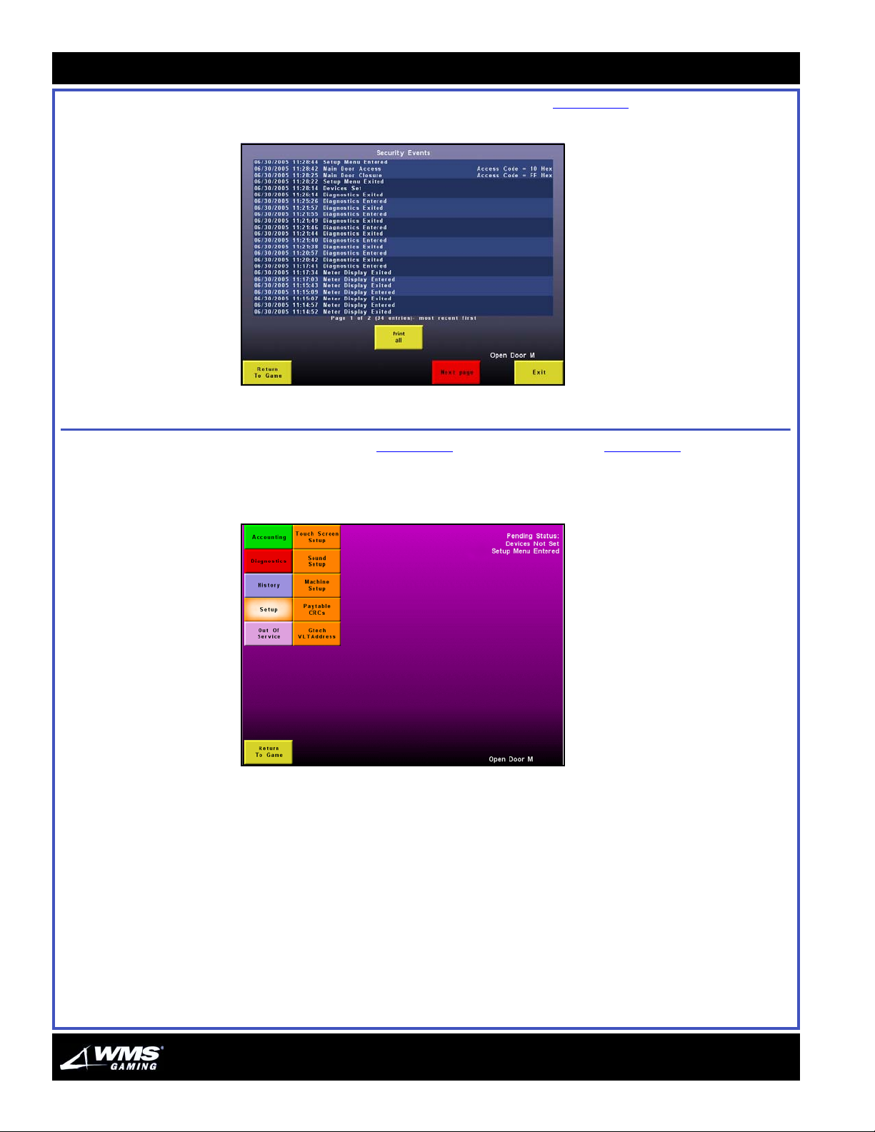
4-32
Setup Menu
Security Events Shows all the security events that were logged, Figure 4-61.
Figure 4-61 Security Events History screen.
Setup Menu The Operator Menu, Figure 4-62, and Attendant Menu, Figure 4-63, are virtually
identical except for security-related options in the Setup Menu. This section
describes the submenus found in the Operator Menu.
Figure 4-62 Operator Menu.
AUGUST 2005
 Loading...