

Page 1
NXTOM080511
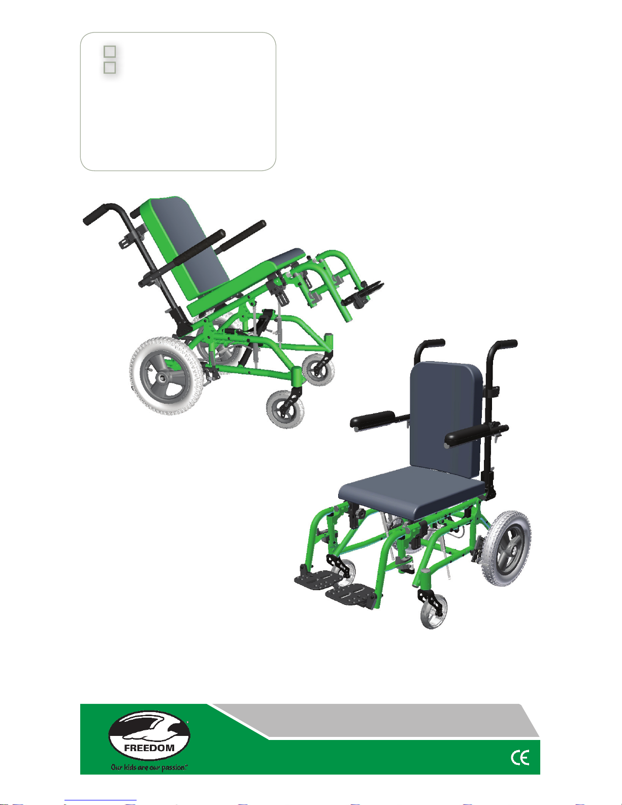
With transport option
Without transport option
Supplier: This manual must be given
to the user/care giver of this
wheelchair.
Rider: Before using this wheelchair,
read this entire manual and
save for future reference.
Pediatric & Adult
Pediatric & Adult
Operator’s Manual
Folding & Rigid Tilt Wheelchair
NXT
Generation NEXT
TM
Folding
Rigid
Page 2

NXT
Generation NEXT
TM
Freedom Designs, Inc.
Freedom Designs, Inc.
Page 3

Freedom Designs, Inc.
Freedom Designs, Inc.
1
NXT
Generation NEXT
TM
Freedom Designs, Inc.
Freedom Designs, Inc.
Congratulations on your purchase of the Freedom Designs, Inc. NXT wheelchair. These
chairs combine state-of-the-art technology with durability and functionality to meet all
of your changing needs. This Operating Manual provides you with a detailed guide for
proper assembly as well as instructions on the care of your new wheelchair. Please follow
the instructions carefully, paying special attention to the Safety Precaution section. It is
important to read the entire Operating Manual before operating the wheelchair. After
consulting your Operating Manual, if you feel you have further questions, please contact
one of our Authorized Providers or our Customer Service Department at:
(800) 331-8551
Again, thank you for your purchasing a Freedom Designs, Inc. NXT
This manual created on August 5th, 2011
Serial #___________________________________
Reference Phone Numbers:
Home Medical Equipment Supplier Name _____________________________
Phone # _____________________________
Home Health Care Agency Name _____________________________
Phone # _____________________________
Doctor Name _____________________________
Phone # _____________________________
Supplier _____________________________________________________
Address: _____________________________________________________
Telephone: _____________________________________________________
Serial # ______________________ Purchase Date ________________
Introduction
Page 4

Freedom Designs, Inc.
Freedom Designs, Inc.
2
NXT
Generation NEXT
TM
Introduction 1
Table of Contents 2
General Warnings 3-5
Weight Limit 3
Every Wheelchair is Different 3
Reduction of Risk of an Accident 3
Safety Checklist 3
Adjustments 3
Environmental Conditions 4
Terrain 4
Street Use 4
Motor Vehicle Safety 4
Assistance 5
Warnings:
Falls & Tip-Overs 5-9
Center of Balance 5
Dressing or Changing Clothes 6
Wheelies 6
Obstacles 6
Reaching or Leaning 6
Moving Backward 7
Ramps, Slopes & Side Hills 7
Transfer 8
Curbs and Steps 8
Stairs and Escalators 9
Warnings:
For Safe Use 9-11
Transport Use 9
Descending a Curb or
Single Step 9
Climbing a Curb or Single Step 10
Climbing Stairs 10
Descending Stairs 10
Tilting Seat 10
Maintenance 11
Warnings:
Components and Options 11-14
Transport Option 11
Anti-Tip Device 11
Armrests 11
Cushions and Sling Seats 11
Fasteners 12
Pneumatic Tires 12
Footrests 12
Positioning Belts 12
Power Drive 13
Push Handles 13
Quick Release Axles 13
Rear Wheels 13
Wheel Locks 13
Modifi ed Seating Systems 13
Upholstery Fabric 14
Initial Inspection Checklist 15
Features - Folding 16
Features - Rigid 17
Unfolding the
NXT 18-19
Folding the
NXT 20-21
Main Frame 22-27
Latch Style Swing Away
Hangers 22
Pop-up Hangers 23
Flip-up Individual Footplates 24
Angle Adjustable Footboard 25
Quick Release Axles 26
Flip Back and “T”- Armrests 26
Fixed Height, Removable 27
Armrests
Adjustable Height Flip Back 27
Armrests
Casters 27
Wheel Locks 27
Folding Back 28
Tilt Operation 28-29
Leverage Bar Operation 29
NXT Adjustments 30-33
Tilt Cable Adjustment 30
Backpost Adjustments 30
Armrest Adjustments 30-31
Caster Fork Adjustments 31
Wheel Lock Adjustments 31
Rear Axle Adjustments 32
Anti-tip Adjustment 32
Pelvic Belt Installation & Use 33
Cleaning 34
Maintenance 34
Storage 34
Troubleshooting 35
Summary 36
Warranty 37
Table of Contents
Page 5
Freedom Designs, Inc.
Freedom Designs, Inc.
3
NXT
Generation NEXT
TM
Warnings and Caution statements included in this manual describe conditions and unsafe
practices which might result in bodily injury or property damage. Read this entire manual
before assembly or operation of this wheelchair. If you do not understand any of the
instructions in this manual, call your authorized Freedom Designs, Inc. provider. Note:
Where they apply, you will also fi nd “Warnings” in other sections of this manual. Heed all
warnings in this section.
General Warnings
!
!
W
W
A
A
R
R
N
N
I
I
N
N
G
G
!
!
The weight limit for the NXT tilt is a 225 lb. person. If the person exceeds the
weight limit (including items carried), damage to your chair, a fall, tip-over or loss
of control may cause severe injury to the rider or others.
Every wheelchair is different. Become familiar with your chair before you
begin riding. Start slowly, with easy, smooth strokes. Be careful not to use too
much force, which might result in tipping over, damage to your chair, a fall, or
loss of control, which may occur and cause severe injury to the rider or others.
Reduction of Risk of an Accident:
1. BEFORE riding, you should be trained in the safe use of this chair by your
health care advisor.
2. Practice bending, reaching and transfers until you know the limit of your ability.
In order to avoid tipping over, have someone help you, until you know what
can cause a fall.
3. Be aware that you must develop your own methods for safe use best suited
to your level of function and ability.
4. NEVER try a new maneuver on your own until you are sure you can do it safely.
5. Get to know the areas where you plan to use your chair. Look for hazards
and learn how to avoid them.
Safety Checklist
1. Before each use of your chair:
2. Make sure the chair rolls easily and that all parts work smoothly. Check for
noise, vibration, or a change in ease of use. (They may indicate low tire
pressure, loose fasteners, or damage to your chair).
3. Repair any problems. Consult your Freedom Designs, Inc. authorized provider
for help in fi nding or correcting the problem.
4. Check to see that both quick-release axles are locked. When locked, the
axle button will “pop out” fully. If not locked, the wheel may come off and
cause you to fall.
Adjustments
1. If you modify or adjust this chair, it may increase the risk of a tip-over UNLESS
you make other changes as well.
2. Before any adjustments or modifi cations are made to your chair, consult
your authorized Freedom Designs, Inc. provider.
3. Unauthorized modifi cations or use of parts not supplied or approved by Freedom
Designs, Inc. may damage the chair structure. This will void the warranty
and may cause a safety hazard.
If you fail to heed these warnings, damage to your chair, a fall, tip-over, or
loss of control may occur and cause severe injury to the rider or others.
Page 6
Freedom Designs, Inc.
Freedom Designs, Inc.
4
NXT
Generation NEXT
TM
W
W
A
A
R
R
N
N
I
I
N
N
G
G
!
!
Environmental Conditions
Use extra care if you must ride your chair on a wet or slick surface. Ask for help,
if you are in doubt.
Contact with water or excess moisture may cause your chair to rust or corrode.
This could cause your chair to fail.
a. Do not use your chair in a shower, pool or other body of water. The
chair tubing and parts are not watertight and may rust or corrode from
the inside.
b. Avoid excess moisture, (for example, do not leave your chair in a damp
bathroom while taking a shower).
c. Dry your chair as soon as you can if it gets wet or if you use water to
clean it.
Terrain
1. Your chair is designed for use on firm, even surfaces such as concrete,
asphalt, and indoor fl oors and carpeting.
2. Do not operate your chair in sand, loose soil, or over rough terrain. This may
damage wheels or axles or loosen fasteners of your chair.
Street Use
1. In most states, wheelchairs are not legal for use on public roads. Be alert to
the danger of motor vehicles on roads or in parking lots.
2. At night, or when lighting is poor, use refl ective tape on your chair and clothing.
3. Due to your low position, it may be hard for drivers to see you. Make eye
contact with drivers before you go forward. When in doubt, yield until you
are sure it is safe.
Motor Vehicle Safety
As identifi ed on the front cover of this user manual, identify whether your chair
has been manufactured with the Transport Option installed.
If your chair is not equipped with the Transport Option:
The
NXT wheelchairs do not meet federal standards for motor vehicle seating.
1. NEVER let anyone sit in this chair while in a moving vehicle.
a. ALWAYS move the rider to an approved vehicle seat.
b. ALWAYS secure the rider with proper motor vehicle restraints.
2. In an accident or sudden stop, the rider may be thrown from the chair. Wheelchair
hip belts will not prevent this and further injury may result from the belts or straps.
3. NEVER transport this chair in the front seat of a vehicle. It may shift and
interfere with the driver.
3. ALWAYS secure this chair so that it can not roll or shift.
4. Do not use any chair that has been involved in a motor vehicle accident.
If your chair is equipped with the Transport Option, see the Transport Option
Warnings.
General Warnings
!
!
If you fail to heed these warnings, damage to your chair, a fall, tip-over, or
loss of control may occur and cause severe injury to the rider or others.
Page 7
Freedom Designs, Inc.
Freedom Designs, Inc.
5
NXT
Generation NEXT
TM
W
W
A
A
R
R
N
N
I
I
N
N
G
G
!
!
Assistance For the Rider:
Everyone who helps you needs to read and follow all warnings and instructions
that apply.
For Attendants
Work with the rider’s doctor, nurse or therapist to learn safe methods best suited
to your abilities and those of the rider.
Tell the rider what you plan to do and explain what you expect the rider to do.
This will put the rider at ease and reduce the risk of an accident
Make sure the chair has push handles. They provide secure points for you to
hold the rear of the chair to prevent a fall or tip-over. Check to make sure push
handle grips will not rotate or slip off.
To prevent injury to your back, use good posture and proper body mechanics.
When you lift or support the rider, bend your knees slightly and keep your back
as straight as you can.
Remind the rider to lean back when you tilt the chair backward.
When you descend a curb or single step, slowly lower the chair in one easy
movement. Do not let the chair drop the last few inches to the ground. This may
damage the chair or injure the rider.
WARNING: FALLS & TIP-OVERS
Center of Balance
The point where this chair will tip forward, back, or to the side depends on its
center of balance and stability. How your chair is setup, the options you select,
and the changes you make affect the risk of fall or tip-over.
1. The most important adjustments are:
a. The position of the rear wheels. The more you move the rear wheels
forward, the more likely your chair will tip over backward.
2. The center of balance is also affected by:
a. A change in setup of your chair, including:
1. The distance between the rear wheels.
2. The seat height, seat angle and position on frame.
3. The backrest angle.
b. A change in your body position, posture or weight distribution.
c. The use of a back pack or other options, and the amount of added
weight.
3. To reduce the risk of an accident:
a. Consult your doctor, nurse, or therapist to fi nd out what axle and caster
position is best for you.
b. Consult your authorized Freedom Designs, Inc. provider BEFORE
you modify or adjust this chair. Be aware that you may need to make
other changes to correct the center of balance.
c. Have someone help you until you know the balance points of you chair
and how to avoid a tip-over.
d. Use anti-tip tubes.
Warning:
Falls & Tip Overs
!
!
If you fail to heed these warnings, damage to your chair, a fall, tip-over, or
loss of control may occur and cause severe injury to the rider or others.
Page 8
Freedom Designs, Inc.
Freedom Designs, Inc.
6
NXT
Generation NEXT
TM
W
W
A
A
R
R
N
N
I
I
N
N
G
G
!
!
Dressing or Changing Clothes
Your weight may shift if you dress or change clothes while seated in this chair.
To reduce the risk of a fall or tip-over:
Rotate the front casters until they are as far forward as possible. This makes
the chair more stable.
Lock wheel locks into place.
Wheelies
“Wheelies”, (tilting the wheelchair backward to its balance point), are extremely
dangerous as the chair may tip over. Freedom Designs, Inc. recommends that
“wheelies” not be attempted.
Obstacles
Obstacles and road hazards (such as potholes and broken pavement), can
damage your chair and may cause a fall, tip-over, or loss of control.
To avoid these risks:
Keep a lookout for danger—scan the area well ahead of your chair as you ride.
Make sure the floor area where you live and work are level and free of
obstacles.
Remove or cover threshold strips between rooms.
Install a ramp at entry or exit doors. Make sure there is not a drop off at the
bottom of the ramp.
To help correct your center of balance:
a. Lean your upper body FORWARD slightly as you go UP over an obstacle.
b. Press your upper body BACKWARD as you go DOWN from a higher to a
lower level.
Keep both of your hands on the handrims as you go over an obstacle.
Never push or pull on an object, (such as furniture or a doorjamb), to propel
your chair.
Reaching or Leaning
If you reach or lean, it will affect the center of balance of your chair. This may
cause you to fall or tip over. When in doubt, ask for help or use a device to
extend your reach.
1. NEVER reach or lean if you must shift your weight sideways or rise up off
the seat.
2. NEVER reach or lean if you must move forward in your seat to do so. Always
keep your buttocks in contact with the backrest.
3. NEVER reach with both hands, you may not be able to catch yourself to
prevent a fall if the chair tips.
4. DO NOT reach or lean over the top of the seat back. This may damage
one or both backrest tubes and cause you to fall.
5. If you must reach or lean:
a. Do not lock the Drive wheels. This creates a tip point and makes a
fall or tip-over more likely.
b. Do not put pressure on the footrests.
Note: Leaning forward puts pressure on the footrests and may cause the
chair to tip if you lean too far.
Warning:
Falls & Tip Overs
!
!
If you fail to heed these warnings, damage to your chair, a fall, tip-over, or
loss of control may occur and cause severe injury to the rider or others.
Page 9
Freedom Designs, Inc.
Freedom Designs, Inc.
7
NXT
Generation NEXT
TM
W
W
A
A
R
R
N
N
I
I
N
N
G
G
!
!
c. Move your chair as close as you can to the object you wish to reach.
d. Do not try to pick up an object from the fl oor by reaching down between
your knees. You are less likely to tip if you reach to the side of your chair.
e. Rotate the front casters until they are as far forward as possible.
This makes the chair more stable.
Note: To do this: Move your chair past the object you want to reach,
then back up alongside it. Backing up will rotate the casters forward.
f. Firmly grasp an armrest with one hand. This will help to prevent a fall if
the chair tips.
Moving Backward
Use extra care when you move backward. Your chair is not stable when you
propel yourself rearward. You may lose control or tip over if one of the large
Drive wheels hits an object and stops rolling.
Propel your chair slowly and smoothly.
Stop often and check to be sure your path is clear.
If you fail to heed these warnings, damage to your chair, a fall, tip-over, or loss
of control may occur and cause severe injury to the rider or others.
Ramps, Slopes & Side Hills
Riding on a slope, which includes a ramp or side hill, will change the center of
balance of your chair. Your chair is less stable when it is at an angle. The rear
stabilizing wheel may not keep the chair from going over backward.
1. Do not use your chair on a slope steeper than 10%. (A 10% slope means:
one foot in elevation for every ten feet of slope length).
2. Always go as straight up and as straight down as you can. (do not “cut the
corner” on a slope or ramp).
3. Do not turn or change direction on a slope.
4. Always stay in the CENTER of the ramp. Make sure ramp is wide enough
that you are not at risk that a wheel may fall over the edge.
5,. Do not stop on a steep slope. If you stop, you may lose control of your chair.
NEVER use wheel locks to try to slow or stop your chair. This is likely to
cause your chair to veer out of control.
7. Beware of:
a. Wet or slippery surfaces.
b. A change in grade on a slope (or a lip, bump or depression). These
may cause a fall or tip-over.
c. A drop-off at the bottom of a slope. A drop-off of as small as 3/4”
can stop a front caster and cause the chair to tip forward.
8. To reduce the risk of a fall or tip-over:
a. Lean or press your body UPHILL. This will help adjust for a change
in the center of balance caused by the slope or side hill.
b. Keep pressure on the handgrips to control your speed on a down slope.
If you go too fast, you may lose control.
c. Ask for help any time you are in doubt.
9. For your safety, ramps at home and work must meet all legal requirements
for your area.
Warning:
Falls & Tip Overs
!
!
If you fail to heed these warnings, damage to your chair, a fall, tip-over, or
loss of control may occur and cause severe injury to the rider or others.
Page 10
Freedom Designs, Inc.
Freedom Designs, Inc.
8
NXT
Generation NEXT
TM
W
W
A
A
R
R
N
N
I
I
N
N
G
G
!
We recommend:
a. Width: At least four feet wide.
b. Guardrails. To reduce the risk of a fall, sides of ramp must have
guardrails (or raised borders at least three inches high).
c. Slope. Not more than a 10% grade.
d. Surface. Flat and even, with a thin carpet or other nonskid material.
(Make sure there is no lip, bump or depression).
e. Bracing. Ramp must be STURDY. You may need a section at the top or
bottom to smooth out the transition.
Transfer
It is dangerous to transfer on your own. It requires good balance and agility. Be
aware that there is a point during transfer when the wheelchair seat is not below
you. To avoid a fall:
1. Work with your health care advisor to learn safe methods.
a. Learn how to position your body and how to support yourself during a
transfer.
b. Have someone help you until you know how to do a safe transfer on
your own.
2. Lock large Drive wheels before you transfer. This keeps the large wheels
from rolling.
Note: This will NOT keep your chair from sliding away from you or tipping.
3. Make sure to keep pneumatic tires properly infl ated. Low tire pressure may
allow the wheel locks to slip.
4. Move your chair as close as you can to the seat you are transferring to. If
possible, use a transfer board.
5. Rotate the front casters until they are as far forward as possible.
6. Remove footboard, if possible.
a. Make sure your feet do not catch in the space between the footrests.
b. Avoid putting excessive weight on the footboard, as this may cause the
chair to tip.
7. Make sure armrests are out of the way and do not interfere.
8. Transfer as far back onto the seat surfaces as you can. This will reduce the
risk that the chair will tip or move away from you.
Curbs & Steps
1. Each person who helps you should read and follow the warnings—”For
Safe Use” (Pages 9-10).
2. Do not try to climb or descend a curb or step alone UNLESS you are a skilled
rider of this chair and you are sure you have the strength and balance to do so.
3. Do not try to climb a high curb or step, more than 4” high, UNLESS you
have help. Doing so may cause your chair to exceed its balance point and
tip over.
4. Go straight up and down a curb or step. If you climb or descend at an angle,
a fall or tip-over is likely.
5. Be aware that the impact of dropping down from a curb or step can damage
your chair or loosen fasteners.
Warning:
Falls & Tip Overs
!
!
!
If you fail to heed these warnings, damage to your chair, a fall, tip-over, or
loss of control may occur and cause severe injury to the rider or others.
Page 11
Freedom Designs, Inc.
Freedom Designs, Inc.
9
NXT
Generation NEXT
TM
Stairs and Escalators
1. NEVER use this chair on stairs UNLESS you have someone to help you.
Doing so is likely to cause a fall or tip-over.
2. Persons who help you should read and follow the warnings “For Attendants”,
(page 6) and the “For Safe Use”, (pages 9-10).
3. NEVER use this chair on an escalator, even with an attendant. If you do, a
fall or tip-over is likely.
WARNING: FOR SAFE USE
Before you assist a rider, be sure to read the warnings “For Attendants” (page 5)
and follow all instructions that apply. Be aware that you will need to learn safe
methods best suited to your abilities.
Transport Use
If possible and feasible, the rider
should transfer to the OEM vehicle
seat and use the vehicle restraint.
If the wheelchair is used for transport, it must be used in a forwardfacing seating position.
The ANSI/RESNA WC/19 standards apply to persons with a
weight of 51 to 169 lbs. This constitutes the range of sizes for which
the wheelchairs are suitable for occupancy in a motor vehicle.
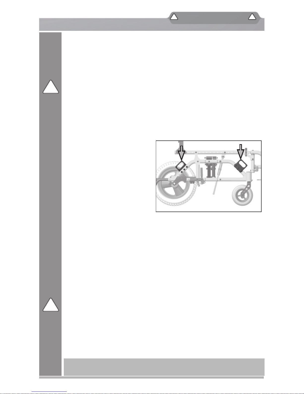
The picture (right) shows the location of the wheelchair securement points.
Use only with Wheelchair Tiedown and Occupant Restraint Systems (WTORS)
that have been installed in accordance with the manufacturer’s instructions and
SAE J2249.
Attach WTORS to securement points in accordance with the manufacturer’s
instructions and SAE J2249
Attach occupant restraints in accordance with the manufacturer’s instructions
and SAE J2249.
Note: To obtain a copy of SAE J2249 Wheelchair Tiedown and Occupant
Restraints Systems for Use in Motor Vehicles, please contact:
SAE International—400 Commonwealth Drive—Warrendale, PA 15096
(412) 776-4970
Descending a Curb or Single Step with Attendant
Follow these steps to help a rider descend a curb or single step going down
BACKWARD:
1. Stay at the rear of the chair.
2. Several feet before you reach the edge of the curb or step, turn the chair
around and pull it backward.
W
W
A
A
R
R
N
N
I
I
N
N
G
G
!
Warning:
For Safe Use
!
!
!
If you fail to heed these warnings, damage to your chair, a fall, tip-over, or
loss of control may occur and cause severe injury to the rider or others.
Page 12
Freedom Designs, Inc.
Freedom Designs, Inc.
10
NXT
Generation NEXT
TM
W
W
A
A
R
R
N
N
I
I
N
N
G
G
!
!
3. While looking over your shoulder, carefully step back until you are off the
curb or stair and standing on the lower level.
4. Pull the chair toward you until the large Drive wheels reach the edge of the
curb or step. Then allow the large Drive wheels to slowly roll down onto the
lower level.
5. When the large Drive wheels are safely on the lower level, tilt the chair back
to its balance point. This will lift the front casters off of the curb or step.
6. Keep the chair in balance and take small steps backward. Turn the chair
around and gently lower front casters to the ground.
Climbing a Curb or Single Step with Attendant
Follow these steps to help the rider climb a curb or single step going FORWARD
1. Stay behind the chair.
2. Face the curb and tilt the chair up on the large Drive wheels so that the front
casters clear the curb or step.
3. Move forward, placing the front caster on the upper level as soon as you are
sure they are past the edge.
4. Continue forward until large wheels contact the face of the curb or step. Lift
and roll the large wheels to the upper level.
Climbing Stairs
1. Use at least two attendants to move a chair and rider up stairs.
2. Move the chair and rider BACKWARD up the stairs.
3. The person at the rear is in control. He or she tilts the chair back to its balance
point.
4. A second attendant at the front fi rmly grasps a non-detachable part of the
front frame and lifts the chair up and over one stair at a time.
5. The attendants move to the next stair up. Repeat for each stair until you
reach the landing.
Descending Stairs
1. Use at least two attendants to move a chair and rider down stairs.
2. Move the chair and rider FORWARD down the stairs.
3. The person at the rear is in control. He or she tilts the chair to the balance
point of the rear wheels and rolls it to the edge of the top step.
4. A second attendant stands on the third step from the top and grasps the chair
frame. He or she lowers the chair one step at a time by letting the rear
wheels roll over the stair edge.
5. The attendants move to the next stair down. Repeat for each stair, until you
reach the landing.
Tilting Seat
1. Set wheel lock prior to seat tilt adjustment.
2. Make sure that the fl oor surface is level when adjusting tilt.
3. Keep both hands on handgrips while using your right foot to tilt seat forward
or back.
Warning:
For Safe Use
!
!
If you fail to heed these warnings, damage to your chair, a fall, tip-over, or
loss of control may occur and cause severe injury to the rider or others.
Page 13
Freedom Designs, Inc.
Freedom Designs, Inc.
11
NXT
Generation NEXT
TM
W
W
A
A
R
R
N
N
I
I
N
N
G
G
!
!
Maintenance
1. Inspect and maintain this chair strictly per instructions on page 34.
2. If you detect a problem, make sure to service or repair the chair before use.
3. At least once a year, have a complete inspection, safety check and service
of your chair made by an authorized Freedom Designs, Inc. provider.
WARNING: COMPONENTS & OPTIONS
Transport Option
1. Use only Wheelchair Tiedown and Occupant Restraint Systems, (WTORS)
which meet the requirements of SAE J2249 Recommended Practice—
Wheelchair Tiedown and Occupant Restraint Systems Use In Motor Vehicles.
Do not use WTORS designed to rely on the wheelchair structure to transfer
occupant restraint loads to the vehicle. Note: Use only a four-point wheelchair
tiedown with an integrated three-point occupant restraint system.
2. The wheelchair has been dynamically tested in a forward-facing mode for a
48-km/h frontal impact. The wheelchair must be forward-facing during transport.
3. In order to reduce the potential of injury to vehicle occupants, wheelchair
mounted accessories, such as trays and respiratory equipment, should be
removed and secured separately.
4. Postural supports and positioning devices should not be relied on for
occupant restraints.
5. Do not alter or substitute wheelchair fame parts, components or seating.
6. Sudden stops or impacts can structurally damage your chair. Chairs involved
in such incidents should be replaced.
Anti-Tip Device
Anti-tip tubes help keep your chair from tipping over backward in most normal
conditions. Freedom Designs, Inc. recommends that the anti-tip tubes be used
at all times and may not be removed from the wheelchair.
1. If modifi cations or adjustments are done to the wheelchair, anti-tip tubes
must be used to prevent tipping backward.
When locked in place, (the “down” position), anti-tip tubes should be BETWEEN
1 1/2” to 2” off the ground.
a. If set too HIGH, they may not prevent a tip-over.
b. If set too LOW, they may ”hang up” on obstacles you can expect in normal
use. If this occurs, you may fall or your chair may tip over.
Caution must always be used when tipping the wheelchair backward.
Armrests
Armrests may detach or fl ip up and will not bear weight of this chair.
1. NEVER lift this chair by the armrests. They may come loose or break.
2. Lift this chair only by non-detachable parts of the frame.
Cushions and Sling Seats
1. Freedom Designs, Inc. sling seats and standard foam cushions are not
designed for the relief of pressure.
Warning:
Components & Options
!
!
If you fail to heed these warnings, damage to your chair, a fall, tip-over, or
loss of control may occur and cause severe injury to the rider or others.
Page 14
Freedom Designs, Inc.
Freedom Designs, Inc.
12
NXT
Generation NEXT
TM
W
W
A
A
R
R
N
N
I
I
N
N
G
G
!
!
2. If you suffer from pressure sores, or if you are at risk that they will occur, you
may need a special seating system or a device to control your posture. Consult
your doctor, nurse, or therapist to fi nd out if you need such a device for your
well-being.
Fasteners
Many of the screws, bolts and nuts on this chair are special high-strength
fasteners. Use of improper fasteners may cause your chair to fail.
1. ONLY use fasteners provided by an authorized Freedom Designs, Inc. provider.
2. Over or under tightened fasteners may fail or cause damage to chair parts.
3. If bolts or screws become loose, tighten them as soon as possible.
Footrests
1. At the lowest point, the footrest should be AT LEAST 2 1/2” off the ground.
If set too LOW, it may “hang up” on obstacles you can expect to fi nd in normal
use. This may cause the chair to stop suddenly and tip forward.
2. To avoid a trip or fall when you transfer:
a. Avoid putting excessive weight on the footrest, as the chair may tip
forward.
3. NEVER lift this chair by the footrest. Footrests are not designed to bear the
weight of this chair.
Pneumatic Tires
Proper infl ation extends the life of your tires and makes your chair easier to use.
1. Do not use this chair if any of the tires is under or over infl ated. Check weekly
for proper infl ation level, as listed on the tire sidewall.
2. Low pressure in a large tire may cause the wheel lock on that side to slip AND
allow the wheel to turn when you do not expect it.
3. Low pressure in any tires may cause the chair to veer to one side and result
in a loss of control.
4. Over infl ated tires may burst.
Positioning Belts
Use positioning belts ONLY to help support the rider’s posture. Improper use of
these belts may cause severe injury to or death of the rider.
1. Make sure the rider does not slide down in the wheelchair seat. If this occurs,
the rider may suffer chest compression or suffocate due to pressure from the
belts.
2. The belts must be snug, but must not be so tight that they interfere with breathing.
You should be able to slide your 2 fi ngers between the belt and the rider.
3. Use positioning belts only with a rider who can cooperate. Make sure the belt
can easily be removed in an emergency.
4. NEVER use positioning belts:
a. As a patient restraint. A restraint requires a doctor’s order.
b. On a rider who is comatose or agitated.
c. As a motor vehicle restraint. In an accident or sudden stop, the rider may
be thrown from the chair. Wheelchair positioning belts will not prevent this
and further injury may result from the belts or straps.
Warning:
For Safe Use
!
!
If you fail to heed these warnings, damage to your chair, a fall, tip-over, or
loss of control may occur and cause severe injury to the rider or others.
Page 15
Freedom Designs, Inc.
Freedom Designs, Inc.
13
NXT
Generation NEXT
TM
W
W
A
A
R
R
N
N
I
I
N
N
G
G
!
!
Power Drive
Freedom Designs, Inc. does not recommend the attachment of power drives to
the
NXT wheelchair.
1. The attachment of power drives to the wheelchair is considered a modifi cation
or alteration to the frame, thus voiding the warranty.
2. Balance and stability may be affected, thereby causing unsafe conditions.
Push Handles
When you have an attendant, make sure that this chair has push handles.
1. Push handles provide secure points for an attendant to hold the rear of this
chair, to prevent a fall or tip-over. Make sure to use push handles when you
have an attendant.
2. Check to make sure push handles grips will not rotate or slip off.
3. DO NOT lift chair with stroller handles or stroller handle extensions.
Quick Release Axles
1. Do not use this chair UNLESS you are sure that both quick release axles are
locked. An unlocked axle may come off during use and cause a fall.
2. An axle is not locked until the quick release button pops out fully. An
unlocked axle may come off during use, resulting in a fall, tip-over or loss of
control and cause injury to the rider or others.
Large Drive Wheels
A change in setup of the large Drive wheels will affect the center of balance of
your chair.
1. The farther you move the large Drive wheel axles FORWARD, the more
likely it is that your chair will tip over backward.
2. Consult your doctor, nurse, or therapist to fi nd the best Drive wheel axle
setup for your chair.
3. Adjust the wheel locks after you make any change to the Drive wheel axles.
a. If you fail to do so, the locks may not work.
b. Make sure lock arms embed in tires at least 1/4” when locked.
Wheel Locks
Wheel locks are NOT designed to slow or stop a moving wheelchair. Use the
wheel locks only to keep the Drive wheels from rolling when your chair is at a
complete stop.
1. NEVER use wheel locks to try to slow or stop your chair when it is moving.
Doing so may cause you to veer out of control.
2. To keep the drive wheels from rolling, always set both wheel locks when you
transfer to or from your chair.
3. Low pressure in a large Drive wheel tire may cause the wheel lock on that
side to slip and may allow the wheel to turn when you do not expect it.
4. Make sure lock arms embed in tires at least 1/4” when locked. If you fail to
do so, the locks may not work.
Modifi ed Seating System
Use of a seating system not approved by Freedom Designs, Inc., may alter the
center of balance of this chair. This may cause the chair to tip over.
Warning:
For Safe Use
!
!
If you fail to heed these warnings, damage to your chair, a fall, tip-over, or
loss of control may occur and cause severe injury to the rider or others.
Page 16
Freedom Designs, Inc.
Freedom Designs, Inc.
14
NXT
Generation NEXT
TM
W
W
A
A
R
R
N
N
I
I
N
N
G
G
!
!
1. Do not change the seating system of your chair UNLESS you consult your
authorized Freedom Designs, Inc. provider fi rst.
2. Use of a seating system not approved by Freedom Designs, Inc. may affect
the folding mechanism of this chair.
3. Use of a seating system not approved by Freedom Designs, Inc. is prohibited
for transportation use with Freedom Designs, Inc. Transport Option.
Upholstery Fabric
1. Sling fabric will weaken with age and use. Look for fraying or thin spots,
stretching of fabrics at rivet holes.
2. “Drooping Down” into your chair will weaken fabric and result in the need to
inspect and replace the seat more often.
3. Be aware that laundering or excess moisture will reduce fl ame retardation of
the fabric.
Warning:
For Safe Use
!
!
If you fail to heed these warnings, damage to your chair, a fall, tip-over, or
loss of control may occur and cause severe injury to the rider or others.
Page 17
Freedom Designs, Inc.
Freedom Designs, Inc.
15
NXT
Generation NEXT
TM
Initial Inspection
Check List
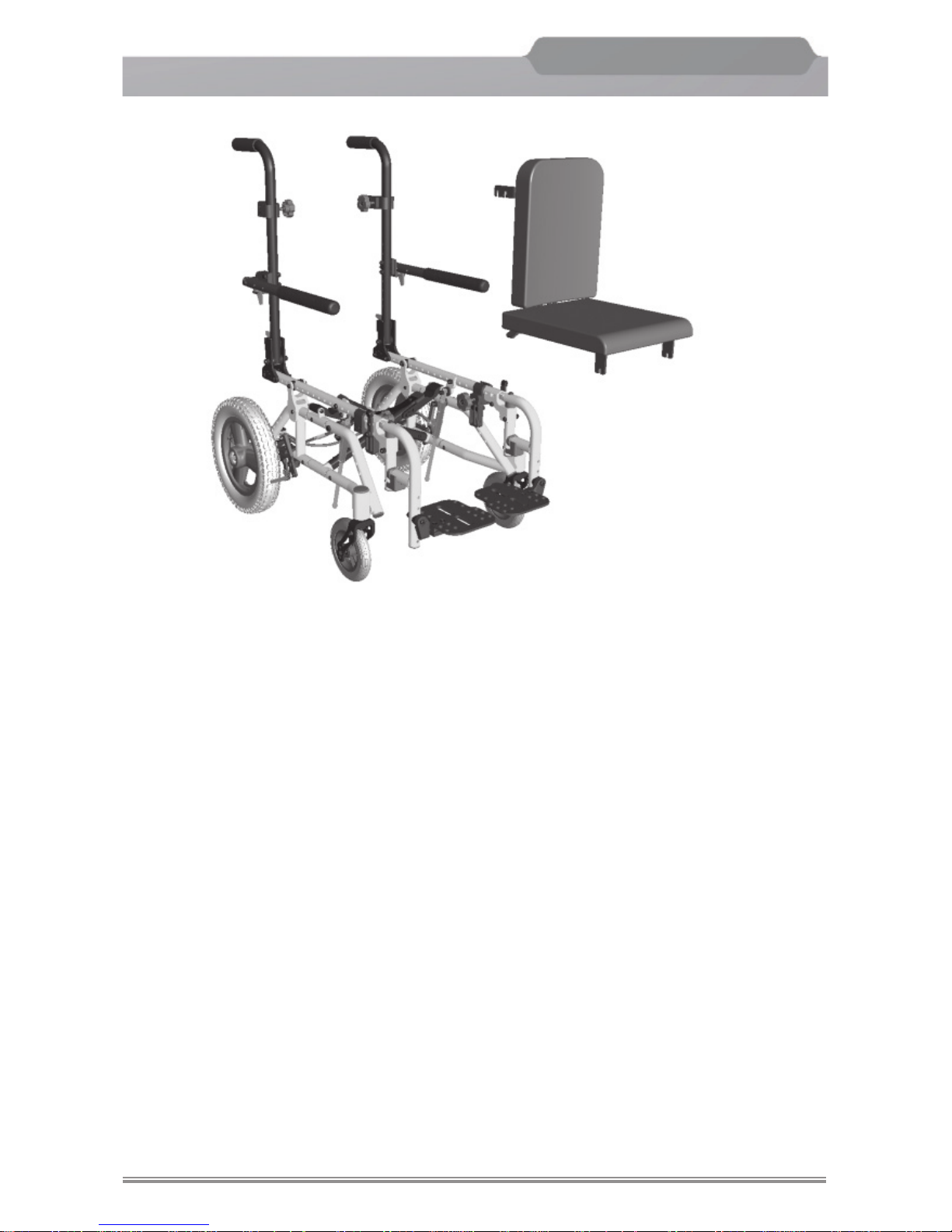
The NXT is shipped in the following fashion:
1. The main frame with backposts, casters, tires, with quick release axles, armrests*,
footplates or footboard and anti-tip tubes. (Refer to the Unfold instructions in this
manual).
2. Optional armrests would be attached to the backposts or solid seat insert.
*Armrest might be optional, dependent upon frame.
When Unpacking:
1. Check for any obvious damage to the box or its contents.
2. Remove all the loose packing from the box.
3. Carefully remove all of the components.
4. Examine the exterior of the
NXT and the components for any nicks, dents, scratches
or other damage.
Page 18
Freedom Designs, Inc.
Freedom Designs, Inc.
16
NXT
Generation NEXT
TM
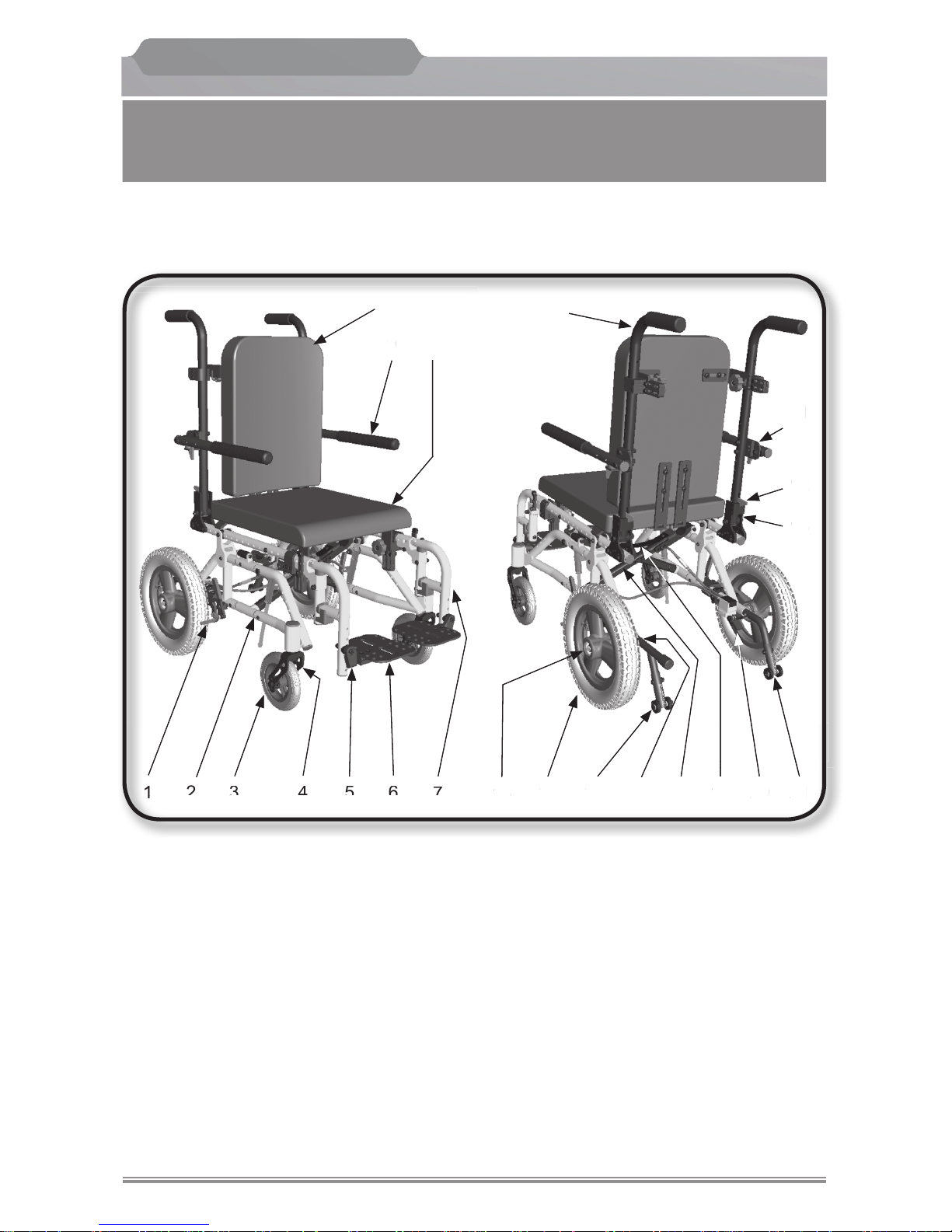
Features - Folding
NXT
1. Wheel Lock
2. Base Frame
3. Caster Wheel
4. Caster Fork
5. Height Adjustable Hanger Clamp
6. Flip-up Footplates
7. Swing Away Hanger
(pop-up or latch style)
8. Solid Seat (optional)
9. Flip up Arm
10. Solid Back (optional)
11. Arm Height Adjustment Clamp
12. Backpost Release Trigger
13. Backpost Adjustment Plate
14. Quick Release Axle
15. 12” Mag Wheel
16. Anti-tip Tube with Leverage Bar
17. Axle Adjustment Plate
18. Folding Crossbraces
19. Lifting / Folding Strap
20. Tilt Release Foot Pedal
21. Anti-tip Tube without Leverage Bar
22. Backpost
14
1
11
19
21
4
8
9
7
17 181615
10
563
13
12
22
2 20
14
1
1
9
21
4
8
9
7
1
8161556
3
1
3
1
2
2
0
Page 19
Freedom Designs, Inc.
Freedom Designs, Inc.
17
NXT
Generation NEXT
TM
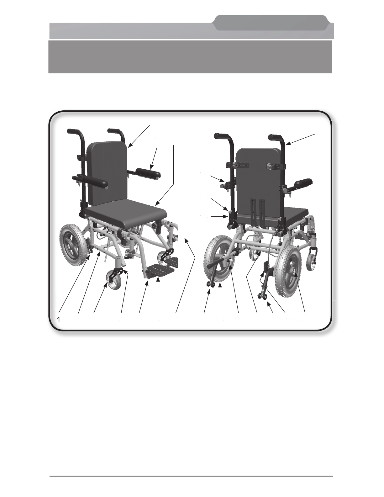
Features - Rigid
NXT
1. Wheel Lock
2. Base Frame
3. Caster Wheel
4. Caster Fork
5. Height Adjustable Hanger Clamp
6. Flip-up Footplates
7. Swing Away Hanger
(pop-up or latch style)
8. Solid Seat (optional)
9. Flip up Arm
10. Solid Back (optional)
11. Arm Height Adjustment Clamp
12. Backpost Release Trigger
13. Backpost Adjustment Plate
14. Anti-tip Tube with Leverage Bar
15. 12” Mag Wheel
16. Axle Adjustment Plate
17. Rigid Crossbraces
18. Anti-tip Tube without Leverage Bar
19. Tilt Release Foot Pedal
20. Quick Release Axle
21. Backpost
14
1
11
19
21
4
8
9
7
17 181615
10
563
13
12
21
2 20
14
1
1
9
21
4
8
9
7
1
81656
3
1
3
1
2
2
0
Page 20
Freedom Designs, Inc.
Freedom Designs, Inc.
18
NXT
Generation NEXT
TM
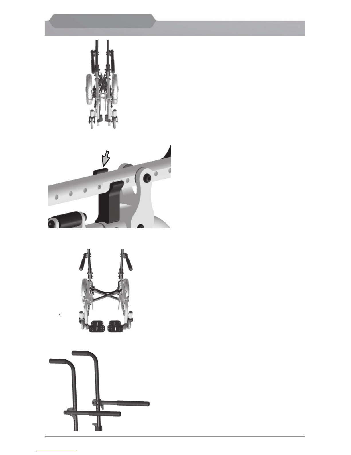
Unfolding the NXT
For ease of transporting and lifting, the
NXT can be easily unfolded and folded.
Always engage the wheel locks by pushing
forward or pulling back on the levers or
engaging the foot lock before unfolding the
chair. (see page 27).
1. Unfolding is accomplished by applying
even downward pressure on the cross
braces. The cross braces will lock into
place.
Note: The cross braces need to be
opened to their maximum point
where the stops rest in the
notches of the cross brace and
lock into place.
2. Grasp the push handles and push them
to an upright position where they will
lock into place in the seat frame receivers.
This operation must always be done
prior to assembling the seating to the
wheelchair.
3. Push the fl ip back armrests down to the
fl at position or insert optional T-arm or
Dual Post Armrests into receiver socket
until it snaps into place.
Seat Frame Receiver
Page 21
Freedom Designs, Inc.
Freedom Designs, Inc.
19
NXT
Generation NEXT
TM
Unfolding the NXT
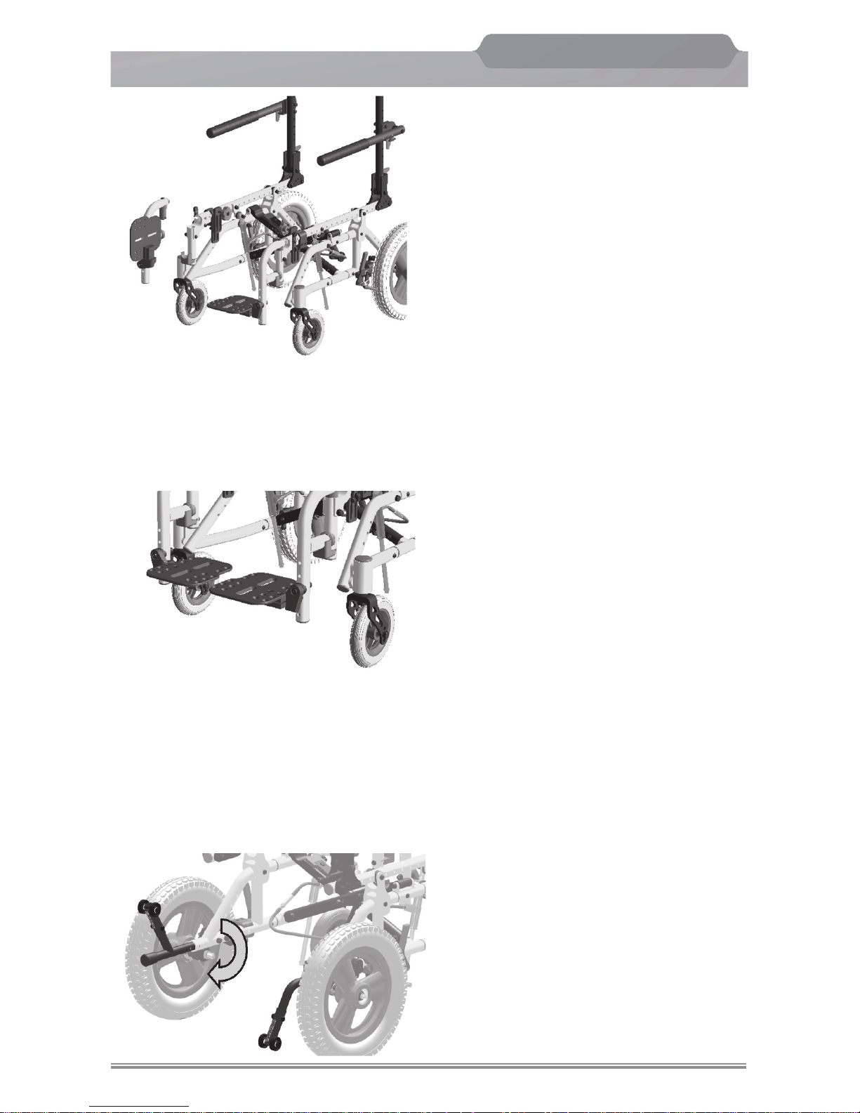
4. Attach Footrest Hangers
(See pages 22-23)
Note: The
NXT can be folded and
unfolded while the footrest
hangers are attached.
5. Flip down the footplates or attach the
footboard and place in the “down” position.
(See pages 24-25)
6. Turn both anti-tip tubes to the downward
position until they “click” into place.
(See page 21).
Page 22
Freedom Designs, Inc.
Freedom Designs, Inc.
20
NXT
Generation NEXT
TM
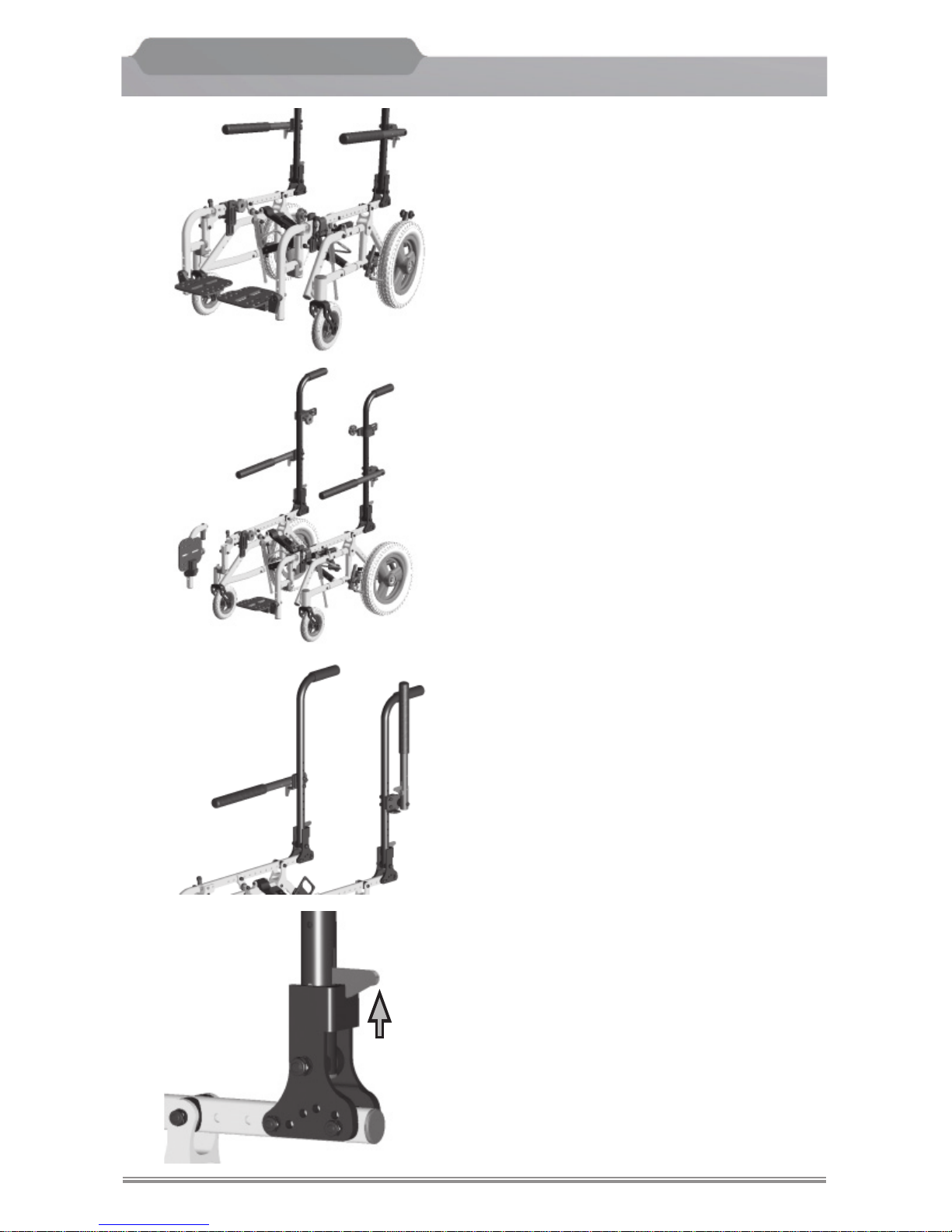
Folding the NXT
Always engage the wheel locks by pushing
forward or pulling back on the levers or
engaging the foot lock before unfolding the
NXT. (see page 27).
1. Flip up the individual footplates or remove
the footboard. (See pages 24-25).
Note: The
NXT can be folded and
unfolded while the footrest
hangers are attached.
2. Remove the footrest hangers.
(See pages 22-23)
3. Flip back the armrests to the upright
position.
Or remove armrests
.
Note:
The armrests need not be removed to
fold the
NXT but must be removed to
fold the backposts down.
4.
Pull up on the trigger mechanism for
the backposts and push the backposts
to the fl at position over the seat rails.
Page 23
Freedom Designs, Inc.
Freedom Designs, Inc.
21
NXT
Generation NEXT
TM
Folding the NXT
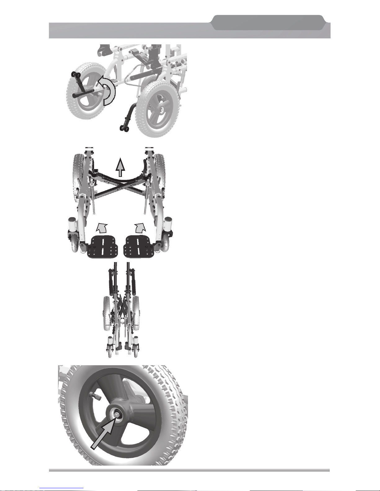
5. Rotate the anti-tip tubes upward as
shown until they “click” into place.
6. Pull up on nylon cross brace strap to
fold the chair.
Note:
Use the provided nylon strap to fold
the chair.
Be careful not to place your fingers
between the folding crossbrace.
7. Disengage wheel lock, push the quick
release axle button and pull wheel off
of the frame.
Page 24
Freedom Designs, Inc.
Freedom Designs, Inc.
22
NXT
Generation NEXT
TM
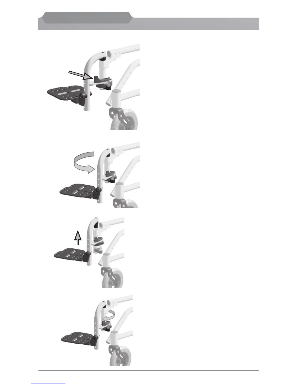
Latch Style Swing Away Hangers
The
NXT frames ship standard with swing-
away hangers in 75° or 90°
1. To swing away the hanger, place your
fi nger tip on the inside of the hanger
release lever.
2. Pull outward on the lever (away from
the chair). This will enable the hanger
to swing away for ease of transfer.
3. To remove the hanger, lift the hanger
upward until the pivot saddle is out of
it’s frame receiver.
4. To attach the hanger, insert the pivot
bushing into the frame receiver tube,
at an angle as shown. Rotate the hanger
inward until the latch snaps into place.
Main Frame
Page 25
Freedom Designs, Inc.
Freedom Designs, Inc.
23
NXT
Generation NEXT
TM
Main Frame
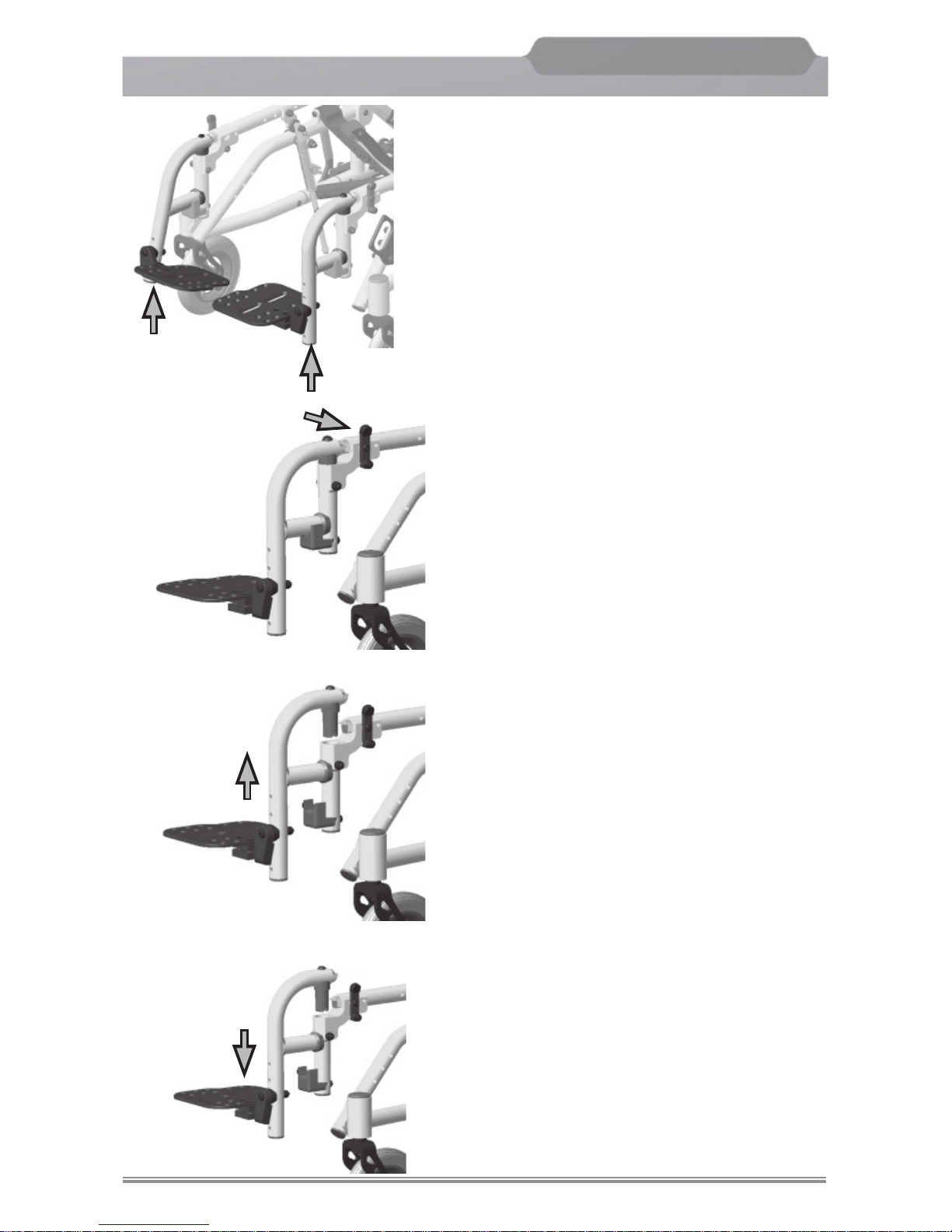
Pop-Up Removable Hangers
The
NXT frames my be shipped with optional
pop-up hangers in 75° or 90°.
1. To remove the hanger, place your hand on
the hanger release lever.
2. Pull back on the lever towards the chair.
This will enable the hanger to pop-up and
swing away for ease of transfer.
3. To remove the hanger, lift the hanger upward
until the pivot saddle is out of it’s receiver
on the frame.
4. To attach the hanger, line up the pivot
saddle with it’s receiver on the frame and
insert downward pressure until hanger
locks into place.
75° hanger
90° hanger
Page 26
Freedom Designs, Inc.
Freedom Designs, Inc.
24
NXT
Generation NEXT
TM
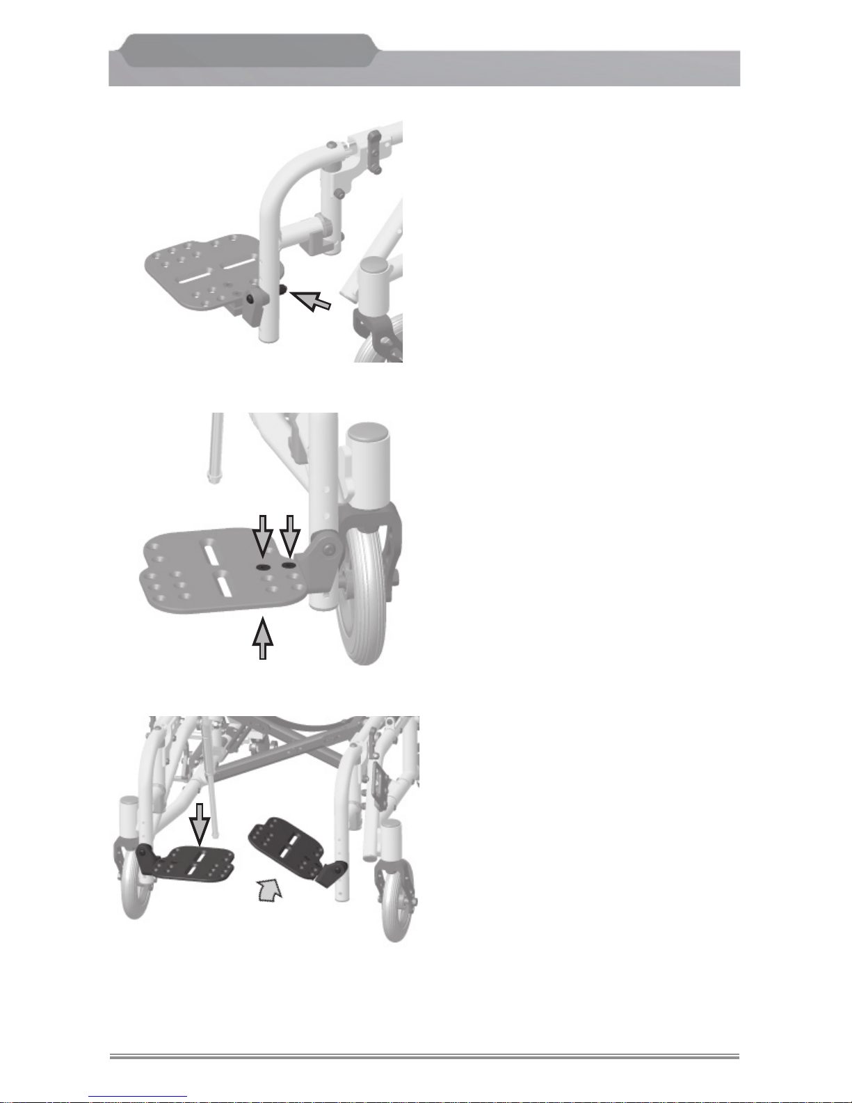
Flip-up Individual Footplates
The
NXT is shipped with individual fl ip-up
footplates attached or a solid footboard
unattached. Adjustment of the individual
fl ip-up footplates are as follows:
To adjust the height of the footplate :
1. Remove the nylon lock nut on the back
side of the hanger. Place the footplate
at the desired height. Insert the screws
through holes in the hanger tube, install
lock nut and tighten securely.
To adjust the angle of the fl ip-up footplate
2. Loosen the screws on bottom of the
footplate.
Set the footplate at the desired angle
and re-tighten.
To adjust the depth of the fl ip-up footplate
3. Loosen and remove the screws on top
of the footplate. Align the holes in the
footplate with holes in the clamp at the
desired depth install the screws and
tighten.
To fl ip the footplate
4. The individual footplates easily fl ip by
lifting underneath the footplate to fl ip
up or push down on the footplate to
fl ip down.
Main Frame
Page 27
Freedom Designs, Inc.
Freedom Designs, Inc.
25
NXT
Generation NEXT
TM
Main Frame
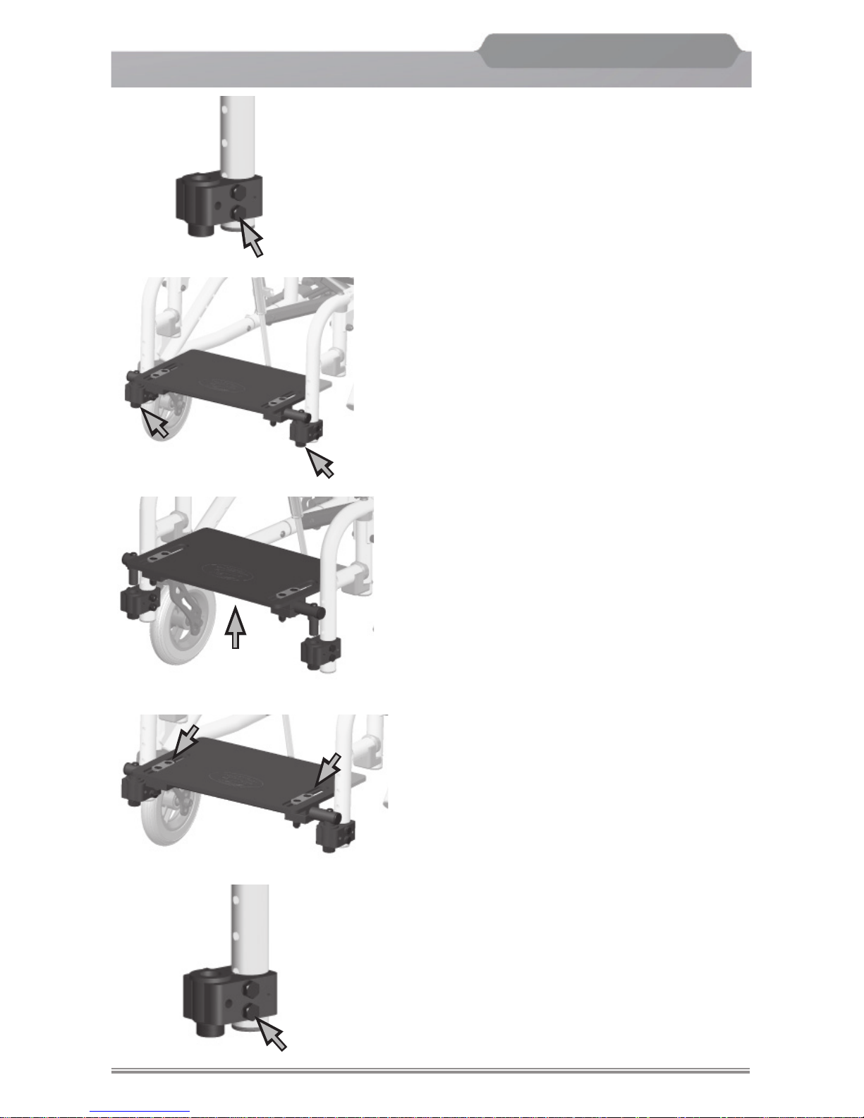
Angle Adjustable Footboard
1. To attach the footboard to the frame, place
the footboard clamps on the frame. Set the
clamps at the desired height. Insert the
receiver into the clamps and tighten the 2
hex head screws on each side.
2. To remove the footboard for transfer, screw the
knob assemblies underneath the receivers.
Lift the footboard upward, out of the receivers.
3. To attach the footboard after transfer, align
the footboard fi ttings into the receivers. Turn
the knobs on each side to tighten.
4. To change the angle of the footboard, use an
allen wrench and loosen the fl at head screws
on the top of the footboard. When the desired
angle or depth is reached, tighten both screws.
5. To change the height of the footboard on the
frame, loosen the 2 hex head screws on the
footboard frame clamps. Set the desired
height and tighten.
The lowest point of the footrest plate should
be at least 2 1/2” from the ground to ensure
the proper clearance.
Warning:
In all footplate and hanger adjustments, be
sure that all screws are tightened securely
for your safety.
Page 28
Freedom Designs, Inc.
Freedom Designs, Inc.
26
NXT
Generation NEXT
TM
Quick Release Axle*
The
NXT is equipped with double lock
quick release axles that release with the
push of a button. This double lock quick
release mechanism allows the rear wheels
to be easily removed for transportation or
storage.
To remove the rear wheel:
1. Unlock the wheel lock.
2. Grasp the frame with one hand.
3. With the other hand, squeeze the quick
release button.
4. The wheel will then pull off easily.
Warning:
The axle is not properly locked until the
outside quick release button pops out
to its full extended position.
*Patented
Flip Back Arm
The
NXT is shipped with fl ip back armrest
as standard equipment. The fl ip back armrests
are non removable and are available in either
locking or non locking.
Locking Flip Back Arm
To fl ip the arm back, push the trigger mecha-
nism
Single Post Height Adjustable “T” Arm
To remove the “T” arm, push lever toward
the center post and lift arm out of receiver
socket.
Main Frame
Page 29
Freedom Designs, Inc.
Freedom Designs, Inc.
27
NXT
Generation NEXT
TM
Main Frame
Casters
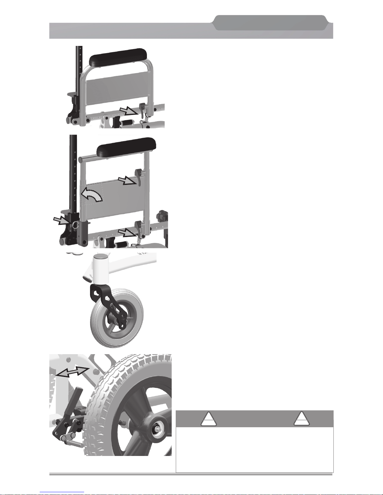
The
NXT comes shipped with either 3” polyure-
thane casters with a 3” caster fork or 5”, 6”, 7”
pneumatic casters with 6” caster fork.
Push or Pull to Lock Wheel Locks
The
NXT comes standard with push to lock or
pull to lock wheel locks.
To lock wheels in place:
1. Grasp the lever of the wheel lock with your
hand.
2. Pull or push the lever back or forward to
release the wheel lock.
Always set the wheel locks when entering or
leaving the wheelchair. Wheel locks are not
designed to slow the wheelchair down when
it is moving. Wheel locks hold the wheelchair
in place when it is at a complete stop.
CAUTION
CAUTION
!
!
Dual Post Fixed Height Armrest
1. To remove the armrest, lift the release lever
at the front of the seat frame and lift the arm
out of the arm receiver tubes.
2. To replace the arm, insert the arm into the
receiver tubes and rotate the release lever
to the downward position.
Dual Post Flip Back Adjustable Height
Armrest
1. To fl ip the arm back, rotate the release lever
at the front of the seat frame, upward to the
horizontal position. The arm is now free to rotate
backward.
2. To adjust the arm height, flip the release
lever (under the front of the arm pad) to
the horizontal position. Slide the arm upward
to the desired location. Flip the release
lever back to the vertical position.
3. To remove the arm, flip the front release
lever to the horizontal position and pull
the pin from the rear receiver tube.
Page 30
Freedom Designs, Inc.
Freedom Designs, Inc.
28
NXT
Generation NEXT
TM
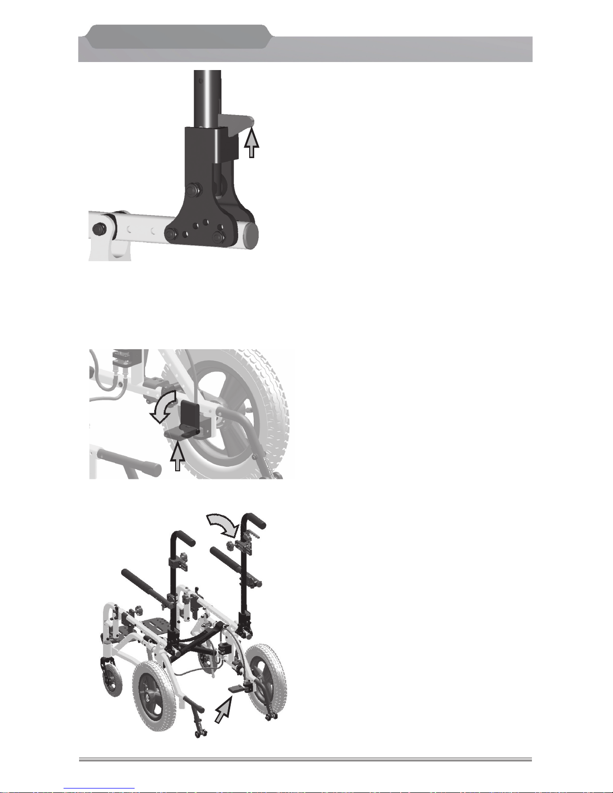
Foot Pedal
Folding Back
The
NXT come standard with a folding
back.
1. To fold the back down, pull upward on
the trigger while pushing backposts
forward toward seat.
2. To place the backpost to the upright
position, pull backposts up until trigger
snaps into place.
Note:
The backposts fold down completely when
using a solid seat and back. When using a
sling seat and back the backposts will only
fold partially
Tilt Operation
The standard method of tilt activation is
with the use of a foot pedal. A single back
cane mounted release is optional.
Foot Pedal Release Procedure
Rearward Tilt
1. Engage wheel locks.
2. To activate the tilt on the
NXT, grip the
push handles with both hands, press
down on the foot pedal and hold down
(fl ip foot pedal down if necessary) and
rotate the push handles downward.
3. When the angle of tilt is in the desired
position, release the foot pressure.
The tilt will lock into place.
Forward Tilt (toward fl at seating position)
1. Engage wheel locks.
2. To bring the
NXT seat and back frame
toward the upright position (out of tilt),
grip the push handles with both hands,
press down on the foot pedal and hold
down, rotate the push handles upward.
3. Release the foot pressure when the
forward tilt position has been achieved.
Main Frame
Foot Pedal
Rotate Back Canes
Page 31
Freedom Designs, Inc.
Freedom Designs, Inc.
29
NXT
Generation NEXT
TM
Main Frame
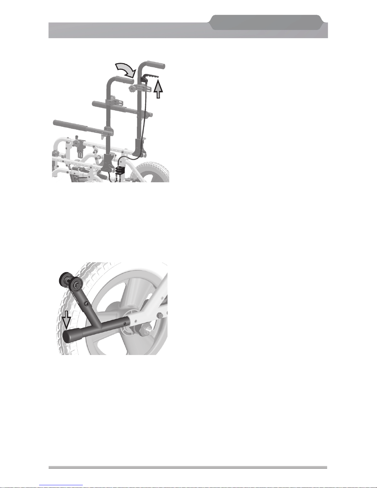
Back Cane Lever Release Procedure
Rearward Tilt
1. Engage wheel locks.
2. To activate the tilt on the
NXT using the
optional back cane mounted lever , grip
the push handles with both hands while
also gripping the release lever. Squeeze
the lever and hold while rotating the push
handles downward.
3. When the angle of tilt is in the desired
position, release the lever.
The tilt will lock into place.
Forward Tilt (toward fl at seating position)
1. Engage wheel locks.
2. To bring the
NXT seat and back frame
toward the upright position (out of tilt),
grip the push handles with both hands,
while gripping the release lever. Squeeze
the lever and hold down while rotating
the back canes upward.
3. Release the pressure on the lever when
the forward tilt position has been achieved.
Leverage Bar Instructions
One of the anti-tip assemblies may be used as a leverage bar to assist in tipping the wheelchair in order
to roll over curbs and other obstacles.
Rotate the anti-tip assemblies to the upward position
(see picture) Place your foot on the straight portion
of the tipping lever. Press down with your foot while
pulling back and pushing downward on the backrest
push handles.
Page 32
Freedom Designs, Inc.
Freedom Designs, Inc.
30
NXT
Generation NEXT
TM
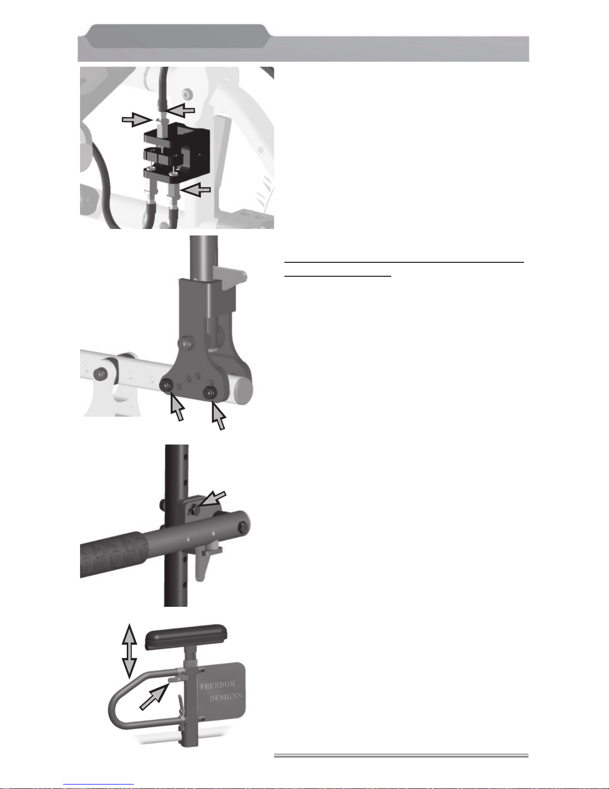
Tilt Cable Adjustment
At least one end of each cable will have a
threaded end fi tting, adjust nut & jam nut.
If the seat tilt locks do not release when the foot
pedal or hand lever is depressed, loosen the
jam nut and adjust the threaded end fi tting out-
ward (turn adjust nut counterclockwise). If the
lock does no hold properly adjust the threaded
end fi tting inward (turn large nut clockwise).
Re-tighten the jam nut securely.
Note:
Seat lock cables should be adjusted by a
qualified technician.
Backpost Adjustment
The angle and depth of the backposts may be
adjusted by repositioning the backpost pivot
plate in the pre-drilled holes on the frame.
Flip Arm / Locking Arm
To adjust height of armrests, loosen and remove
the bolts and nuts holding the arm to the backpost
tube. Align holes in arm with holes in backpost
tube at desired height. Re-assemble with bolts
and nuts.
“T” Arm
To adjust the height of the “T” arm, rotate lever
outward. Lift or lower arm pad to desired height
and rotate lever back to forward position to lock
in place.
Adjustments
Threaded End
Fitting
Adjust Nut
Jam Nut
Page 33
Freedom Designs, Inc.
Freedom Designs, Inc.
31
NXT
Generation NEXT
TM
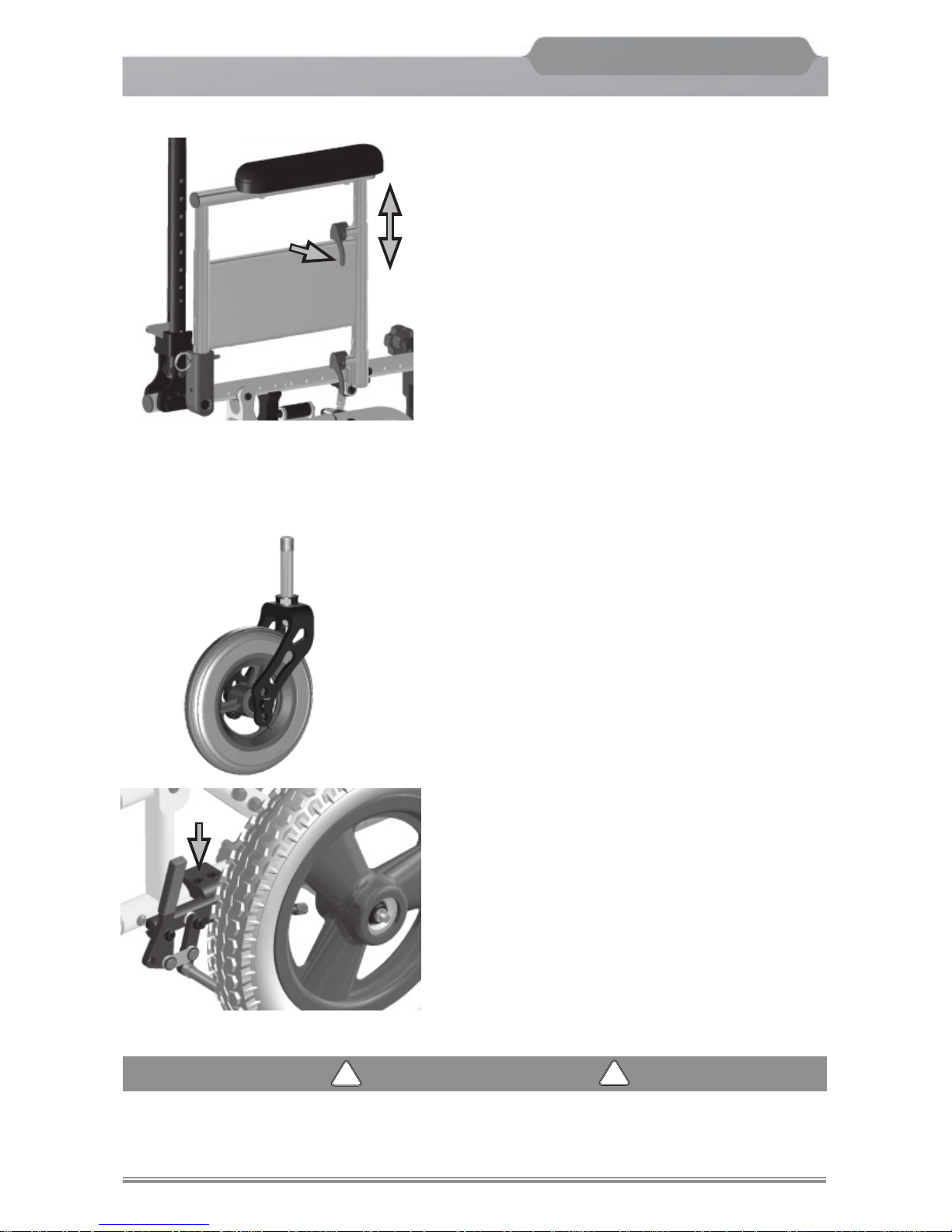
Caster Fork Adjustment
Interchanging casters can easily be done with
dual hole caster forks. Currently, 3”, 5” , 6”
and 7” casters are available for use. A smaller
fork is used with the 3” caster only. To adjust,
loosen the bolt and remove the caster. Change
the caster and/or position the caster upward
or downward in pre-drilled holes on the caster
fork. Replace the bolt and tighten securely.
Wheel Lock Adjustment
When the rear wheel is repositioned, it is important
that the wheel lock is readjusted also.
Adjustment can be made by loosening the
1/4-20 x 1” button head screws and sliding the
wheel lock assembly along the frame tubing so
that the wheel lock contacts the tire in the locked
position. Continue to adjust until the knurled
grip handle embeds into the tire approximately
1/4” when in the locked position. Tighten the
screw until wheel lock is snug to frame tube.
WARNING
WARNING
!
!
Wheel locks are not designed to slow the chair down when it is moving. When the
chair is stopped, engaging properly adjusted wheel locks will prevent the rear
wheels from turning.
Adjustments
Adjustable Height Flip Back Armrest
To adjust the arm height, flip the release
lever (under the front of the arm pad) to
the horizontal position. Slide the arm upward
to the desired location. Flip the release
lever back to the vertical position.
Page 34
Freedom Designs, Inc.
Freedom Designs, Inc.
32
NXT
Generation NEXT
TM
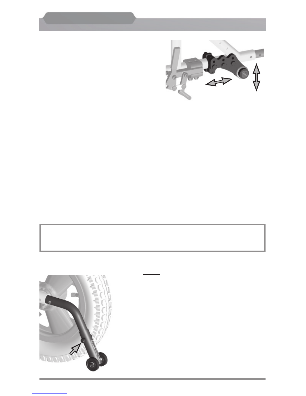
Rear Axle Adjustment
The position of the rear axle is the most critical
adjustment on the
NXT wheelchair. The center
of gravity and the seat height position are all
determined by the axle adjustment.
Warning:
Your healthcare professional should assist
you in adjusting the axle position. Position
of the axle will be based on your abilities
and limitations.
Center of gravity adjustment may be accomplished by moving the rear axle plate forward or
backward on the frame.
Seat height and/or angle may be changed by changing the position of the axle upward
or downward on the axle plate.
Warning:
Your healthcare professional should assist you in adjusting the axle position.
Position of the axle will be based on your abilities and limitations.
Warning:
The wheelchairs become less stable if forward axle positions are used. The further
forward the axles are positioned, the easier it is to tip the chair over forward or
backward. Moving the axle backward will increase the stability of the chair. This
backward adjustment will create increased turning pressure.
Note:
A front caster adjustment should be made to correspond with any changes in
rear seat height/angle.
Anti-tip Lever Adjustment
Height
1. Loosen the screw and nut on the anti-tip
roller assembly.
2. Raise or lower anti-tip roller assembly until
desired height is attained.(recommended
at 1-1/2” to 2” off of the ground).
3. Re-install screw and nut. Tighten securely.
4. Repeat procedure on opposite anti-tip lever.
Adjustments
Page 35
Freedom Designs, Inc.
Freedom Designs, Inc.
33
NXT
Generation NEXT
TM
Freedom Designs, Inc.
Freedom Designs, Inc.
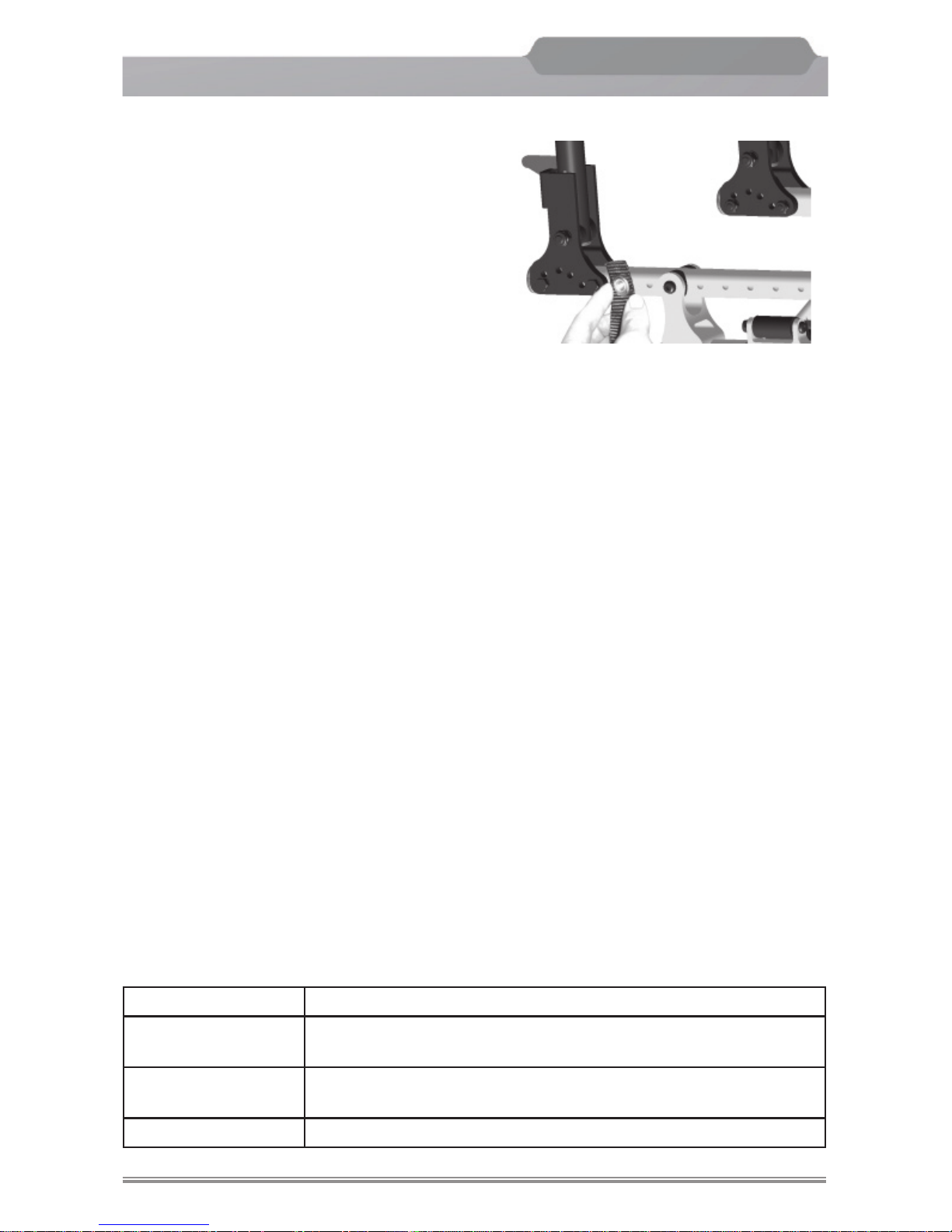
Pelvic Belt Installation
1. Remove the pelvic belt and component from
packaging.
2. Inspect the belt and hardware to ensure that
there are no missing or damaged parts.
3. (2-point belts)
Locate the rear most hole in the seat frame
tube of the wheelchair. Slide a washer onto
screw and insert through the grommet or
triangular bracket (depending on belt type)
and last hole in seat rail tube. Install washer
and lock nut.
Repeat procedure on opposite side of the chair.
Tighten all hardware securely.
(4-point belts)
Locate the rear most hole in the seat frame tube of the wheelchair. Slide a washer
onto screw and insert through the grommet or triangular bracket (depending on belt type)
of the rear belt (thicker strap) and last hole in seat rail tube. Install washer and
lock nut. Next locate a hole in the seat frame 2”-3” forward of the other strap.
Repeat assembly procedure for forward strap.
Repeat assembly procedure for opposite side of the chair.
Tighten all hardware securely.
Pelvic Belt Adjustment
Ensure that the user is sitting correctly, with their bottom as far back in the seat as possible.
Position the lap belt around the user in the desired position and push the two sides of
the buckle together.
Adjust the length of the lap strap using the pulls on the side(s) of the clasp. The belt
should be a snug fi t without causing discomfort. There should be suffi cient room to
slide two fi ngers between the user and the belt. For ease, the clasp should be kept in
a central position.
To Release the Belt
See table below for release instructions.
Pelvic Belt Style Release Instructions
Squeeze
Using the thumb and forefinger, squeeze the two plastic
buttons at the top and bottom of the buckle
Push Button
(Plastic and Metal)
Push the button in the center of the buckle.
Airline Lift the metal flap on the buckle
Adjustments
Page 36

Freedom Designs, Inc.
Freedom Designs, Inc.
34
NXT
Generation NEXT
TM
Cleaning
It is important for optimum performance to clean and maintain your
NXT.
We recommend that the frame fi nish be cleaned with mild soap and water.
Maintenance
1. In order to operate the
NXT properly and safely, routine maintenance will extend
the life and effi ciency of your wheelchair.
Safety Inspection Checklist
Follow these maintenance procedures for optimum performance of your
NXT wheel-
chair:
1. Check to see that the wheelchair rolls straight.
2. Tires: Check for fl at spots, wear and proper infl ation.
3. Wheel lock:
a. Check to see that the locks engage easily.
b. Check that the locks are free of wear
c. Check to see that the locks do not interfere with the tires when rolling.
4. Ensure that all fasteners are secure.
5. Casters: Inspect axle for proper tension. Spin the caster. The caster should spin
freely and come to a gradual stop.
Storage
The
NXT folds down to a small unit and the rear wheels may be removed. We suggest
when storing the wheelchair, that it be stored in an indoor, cool and dry area.
Checklist & Storage
Page 37
Freedom Designs, Inc.
Freedom Designs, Inc.
35
NXT
Generation NEXT
TM
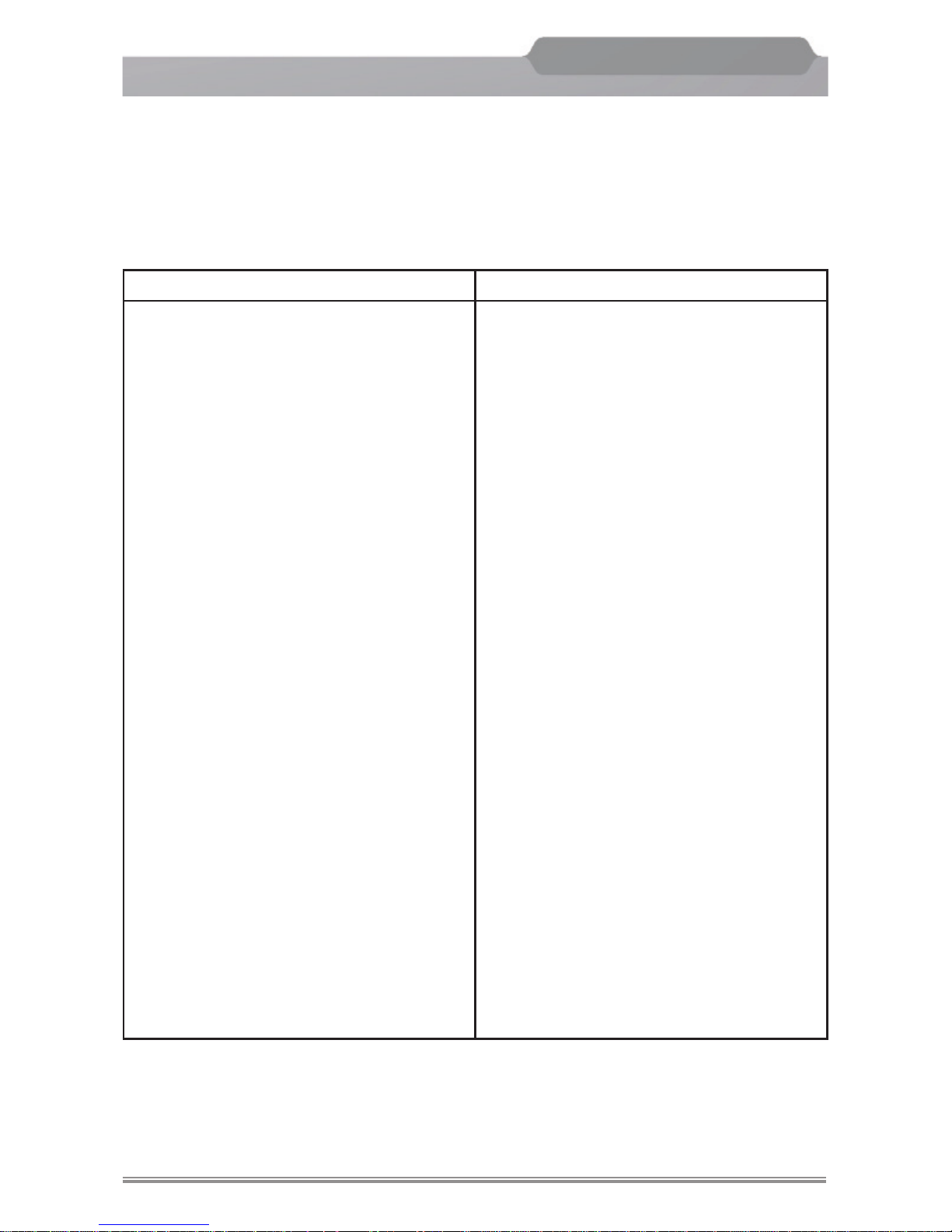
All NXT wheelchairs leave the factory inspected and adjusted for immediate use, (aside
from the unfolding procedure). This troubleshooting chart offers some suggestions
regarding the use of your wheelchair. Some areas may require more investigation to fi nd the most suitable solution for a specifi c problem. A complete inspection,
safety check, and servicing should be made by an authorized provider at least once a
year. Any problems should be directed to your authorized provider or call our customer
service department.
Symptoms Remedy
The wheelchair veers right: Check that both casters contact the
ground at the same time.
Check that the tire pressure is correct
and equal in both rear wheels.
The wheelchair veers left: Check that both casters contact the
ground at the same time.
. Check that the tire pressure is correct
and equal in both rear wheels
Sluggish turning or performance: Check that all nuts and bolts are
tight.
Check that the tire pressure is correct
and equal in rear wheels.
Caster flutter: Check that all nuts and bolts are
tight.
Check that both casters contact the
ground at the same time.
Check for wear of casters.
Squeaks and rattles: Check that all nuts and bolts are
tight.
Looseness in the wheelchair: Check that all nuts and bolts are
tight.
Troubleshooting
Page 38

Freedom Designs, Inc.
Freedom Designs, Inc.
36
NXT
Generation NEXT
TM
Congratulations on your NXT purchase. Following is a brief summary to refer to if you
have any questions. Remember: the entire Operating Manual should be read before
your new chair is used. For any questions, please call your authorized Freedom Designs, Inc. provider or Freedom Designs, Inc. customer service at:
1-800-331-8551
Note: Always lock the wheel locks before adjusting the wheelchair.
Unfolding the
NXT:
1. Place tires on quick release axles and push in until quick release push button
“pops out” and wheels are secure.
2. Apply even pressure on the seat rails and push down.
3. Fold down arms or install armrests.
4. Attach hangers
5. Push footplates down or attach the footboard.
6. Adjust anti-tip tubes to the downward or rearward position.
Folding the
NXT:
1. Flip up the individual footplates or remove the solid footboard.
2. Remove footrest hangers.
3. Fold up or remove armrests.
4. Pull up on nylon crossbrace strap to fold chair.
5. Squeeze quick release axle button and pull wheel off of the frame.
Quick Release Axle:
1. Unlock the wheel locks.
2. Grasp the frame with one hand.
3. With your other hand, squeeze the quick release button.
4. The wheel will then pull off easily.
Push to Lock Wheel Lock: To Lock
1. Grasp the lever of the wheel lock with your hand.
2. Push the lever forward to a locked position.
To Unlock
1. Grasp the lever of the wheel lock with your hand.
2. Pull the lever back to release the wheel lock.
Summary
Page 39

Freedom Designs, Inc.
Freedom Designs, Inc.
37
NXT
Generation NEXT
TM
Freedom Designs, Inc. Limited Warranty
PLEASE NOTE: THE WARRANTY BELOW HAS BEEN DRAFTED TO COMPLY WITH U.S. FEDERAL
LAW APPLICABLE TO PRODUCTS MANUFACTURED AFTER JULY 4, 1975. THIS WARRANTY IS
EXTENDED ONLY TO THE ORIGINAL PURCHASER/USER WHO PURCHASES THIS PRODUCT WHEN
NEW AND UNUSED DIRECTLY FROM FREEDOM DESIGNS OR AN AUTHORIZED DEALER OR
DISTRIBUTOR. THIS WARRANTY GIVES SPECIFIC LEGAL RIGHTS AND YOU MAY ALSO HAVE OTHER
LEGAL RIGHTS WHICH VARY FROM STATE TO STATE, OR COUNTRY TO COUNTRY.
Limited Warranty – USA: All Freedom Designs’ wheelchair frames, quick release axles and hardware are warranted
against defects in material and workmanship for fi ve (5) years from the date of purchase. All other manufactured and
distributed parts and components (including frame components, axle plates, armrests and backrests) are warranted
for one (1) year from said purchase date. There is no warranty for tires, tubes, and push handle grips. If within such
warranty periods any product component eligible for coverage under this warranty shall be proven to be defective,
Freedom Designs will, at its option, either replace or repair the product with new or refurbished product components,
or will supply the original purchaser with replacement product components, which may be either new or refurbished.
Freedom Designs’ sole obligation and your exclusive remedy under this warranty shall be limited to such repair and/or
replacement. This warranty does not include any labor or shipping charges incurred in replacement part installation or
repair. Moreover, the warranty period of the repaired or replaced product component shall terminate with the termination
of the warranty period for the original product component Freedom Designs’ sole obligation and your exclusive remedy
under this warranty shall be limited to such repair and/or replacement.
Limited Warranty - International: All Freedom Designs’ wheelchair frames & quick release axles are warranted against
defects in material and workmanship for fi ve (5) years from the date of purchase. All other manufactured and distributed
parts and components (including frame components, axle plates, armrests and backrests) are warranted for one (1) year
from said purchase date. All hardware is warranted for two (2) years after the date of purchase. There is no warranty for
tires, tubes, and push handle grips. If within such warranty periods any product component eligible for coverage under
this warranty shall be proven to be defective, Freedom Designs will, at its option, either repair or replace the product with
new or refurbished product components, or will supply the original purchaser with replacement product components,
which may be either new or refurbished. Freedom Designs’ sole obligation and your exclusive remedy under this warranty
shall be limited to such repair and/or replacement. This warranty does not include any labor or shipping charges incurred
in replacement part installation or repair. Moreover, the warranty period of the repaired or replaced product component
shall terminate with the termination of the warranty period for the original product component. Freedom Designs’ sole
obligation and your exclusive remedy under this warranty shall be limited to such repair and/or replacement.
Limitations & Exclusions – USA & International: The foregoing limited warranties shall not apply to: Tires, tubes and
push handle grips; Serial numbered products if the serial number has been removed or defaced; Products subjected
to negligence, accident, improper operation, maintenance, or storage; Products modifi ed without Freedom Designs’
express written consent including, but not limited to, modifi cation through the use of unauthorized parts or attachments;
Products damaged by reason of repairs made to any component without the specifi c consent of Freedom Designs, or to
products damaged by circumstances beyond Freedom Designs’ control; Problems arising from normal wear or failure to
adhere to these instructions; and with any such warranty eligibility evaluation to be solely determined by Freedom Designs;.
THE FOREGOING LIMITED WARRANTIES ARE EXCLUSIVE AND IN LIEU OF ANY OTHER WARRANTIES
WHATSOEVER, WHETHER EXPRESS OR IMPLIED, INCLUDING THE IMPLIED WARRANTIES OF
MERCHANTABILITY AND FITNESS FOR A PARTICULAR PURPOSE, AND THE SOLE REMEDY FOR
VIOLATIONS OF ANY WARRANTY WHATSOEVER SHALL BE LIMITED TO REPAIR OR REPLACEMENT
OF THE DEFECTIVE PRODUCT PURSUANT TO THE TERMS CONTAINED HEREIN. THE APPLICATION
OF ANY IMPLIED WARRANTY WHATSOEVER SHALL NOT EXTEND BEYOND THE DURATION OF THE
EXPRESS WARRANTY PROVIDED HEREIN. FREEDOM DESIGNS SHALL NOT BE LIABLE FOR ANY
CONSEQUENTIAL OR INCIDENTAL DAMAGES WHATSOEVER. THESE WARRANTIES SHALL BE
EXTENDED TO COMPLY WITH STATE PROVINCIAL LAWS AND REQUIREMENTS.
Returns: An authorization for return must be acquired by an established Freedom Designs, Inc. dealer/distributor
before Freedom Designs will accept returned items. The dealer must return items to Freedom Designs, 2241 N.
Madera Rd, Simi Valley, CA 93065 USA with freight pre-paid and fully insured with the R.A. # issued by customer
service marked on the outside of the box. All returns must be received within 45 days of issuance of the R.A. #.
Returns are subject to examination at the discretion of Freedom Designs and may be subject to a 25% restocking
fee. Custom fabricated products are non-returnable.
Warranty
Page 40

FREEDOM DESIGNS, INC. 2241 Madera Rd. Simi Valley, CA. 93065 800-331-8551 Fax 888-582-1509
www.freedomdesigns.com
 Loading...