

Page 1
UM11036
Point of Sales (POS) Reader Solution - Quick Start Guide
Rev. 1.2 — 7 February 2017
406512
User manual
COMPANY PUBLIC
Document information
Info
Content
Keywords
Point of Sales (POS) Reader Solution, K81, PN5180, TDA8035
Abstract
This document intends to describe all steps that should be applied in
order to start with the POS Reader Solution kit
Page 2

NXP Semiconductors
UM11036
Point of Sales (POS) Reader Solution - Quick Start Guide
UM11036
All information provided in this docum ent is subject to legal disclaimers.
© NXP Semiconductors N.V. 2017. All rights reserved.
User manual
COMPANY PUBLIC
Rev. 1.2 — 7 February 2017
406512
2 of 56
Contact information
For more information, please visit:
http://www.nxp.com
Revision history
Rev
Date
Description
1.2
20170207
PN5180 Firmware update procedure added
1.1
20161116
Update for CES release
1.0
20161110
First release
Page 3
NXP Semiconductors
UM11036
Point of Sales (POS) Reader Solution - Quick Start Guide
UM11036
All information provided in this document is subject to legal disclaimers.
© NXP Semiconductors N.V. 2017. All rights reserved.
User manual
COMPANY PUBLIC
Rev. 1.2 — 7 February 2017
406512
3 of 56
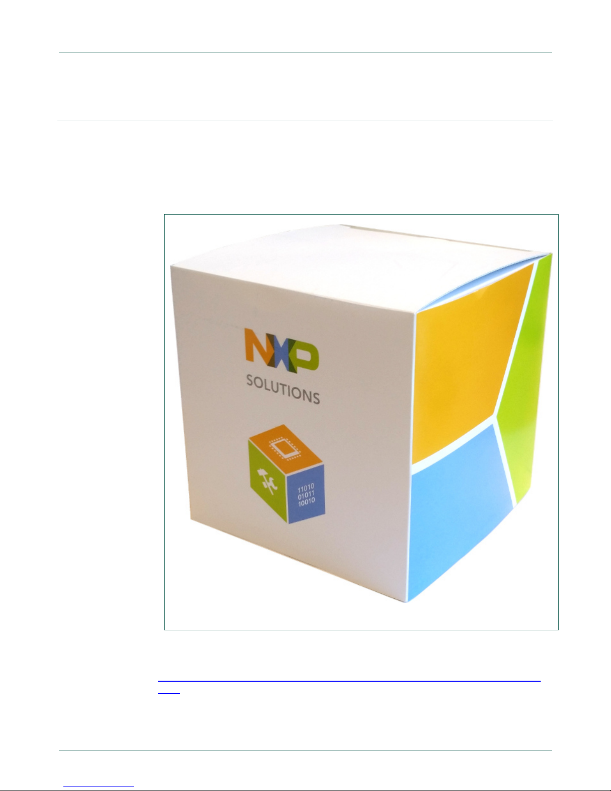
1. Introduction
The K81 point-of-sale (POS) Card Reader Solution is a collection of hardware, software
enablement, middleware and specialized application-specific software for the point-ofsale market. This document describes how to start with the kit: use it for payment
application demonstration and start working with the dedicated software.
Fig 1. POS Reader Solution Kit box
All details about the solution can be found on the NXP webpage:
www.nxp.com/products/reference-designs/point-of-sale-pos-reader-solution:SLN-POSRDR
Page 4
NXP Semiconductors
UM11036
Point of Sales (POS) Reader Solution - Quick Start Guide
UM11036
All information provided in this document is subject to legal disclaimers.
© NXP Semiconductors N.V. 2017. All rights reserved.
User manual
COMPANY PUBLIC
Rev. 1.2 — 7 February 2017
406512
4 of 56
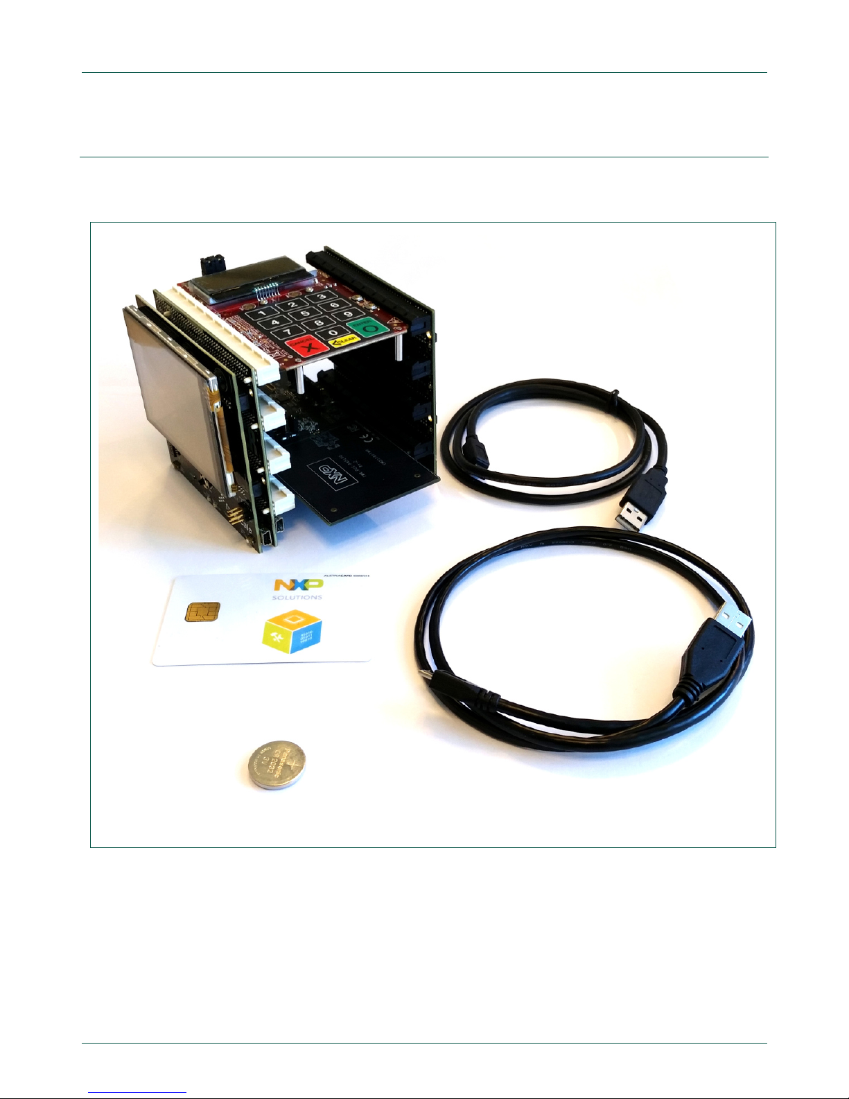
2. POS Reader Solution kit
2.1 Kit Content
Fig 2. Kit Content
The individual components of the POS Reader Solution Kit are described in the below
subsections.
Page 5
NXP Semiconductors
UM11036
Point of Sales (POS) Reader Solution - Quick Start Guide
UM11036
All information provided in this document is subject to legal disclaimers.
© NXP Semiconductors N.V. 2017. All rights reserved.
User manual
COMPANY PUBLIC
Rev. 1.2 — 7 February 2017
406512
5 of 56
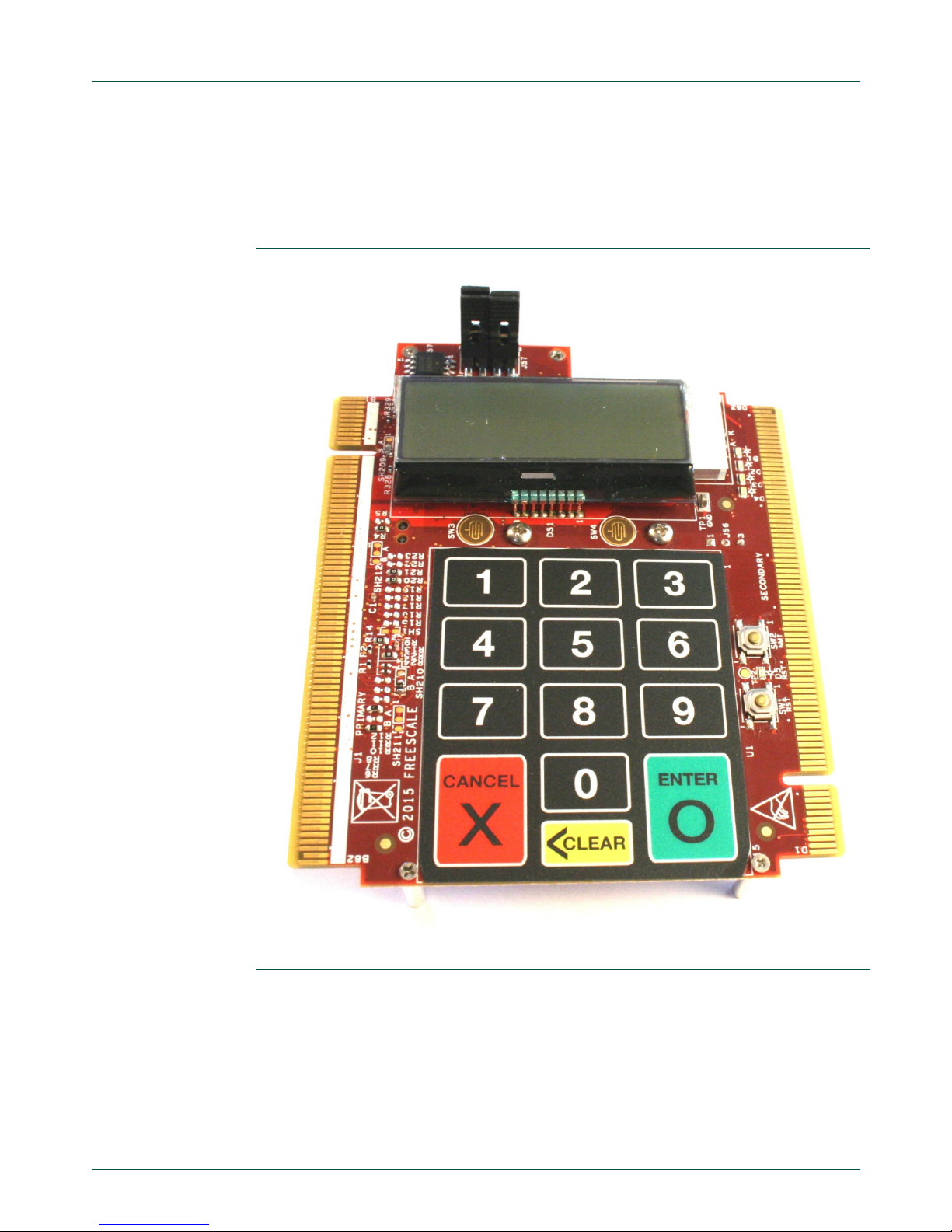
2.1.1 TWR-POS-K81
This is the core of the SLN-POS-RDR system. This board embeds the K81
microcontroller, external flash, an LCD display and the secure pin pad.
Fig 3. TWR-POS-K81
Page 6
NXP Semiconductors
UM11036
Point of Sales (POS) Reader Solution - Quick Start Guide
UM11036
All information provided in this document is subject to legal disclaimers.
© NXP Semiconductors N.V. 2017. All rights reserved.
User manual
COMPANY PUBLIC
Rev. 1.2 — 7 February 2017
406512
6 of 56
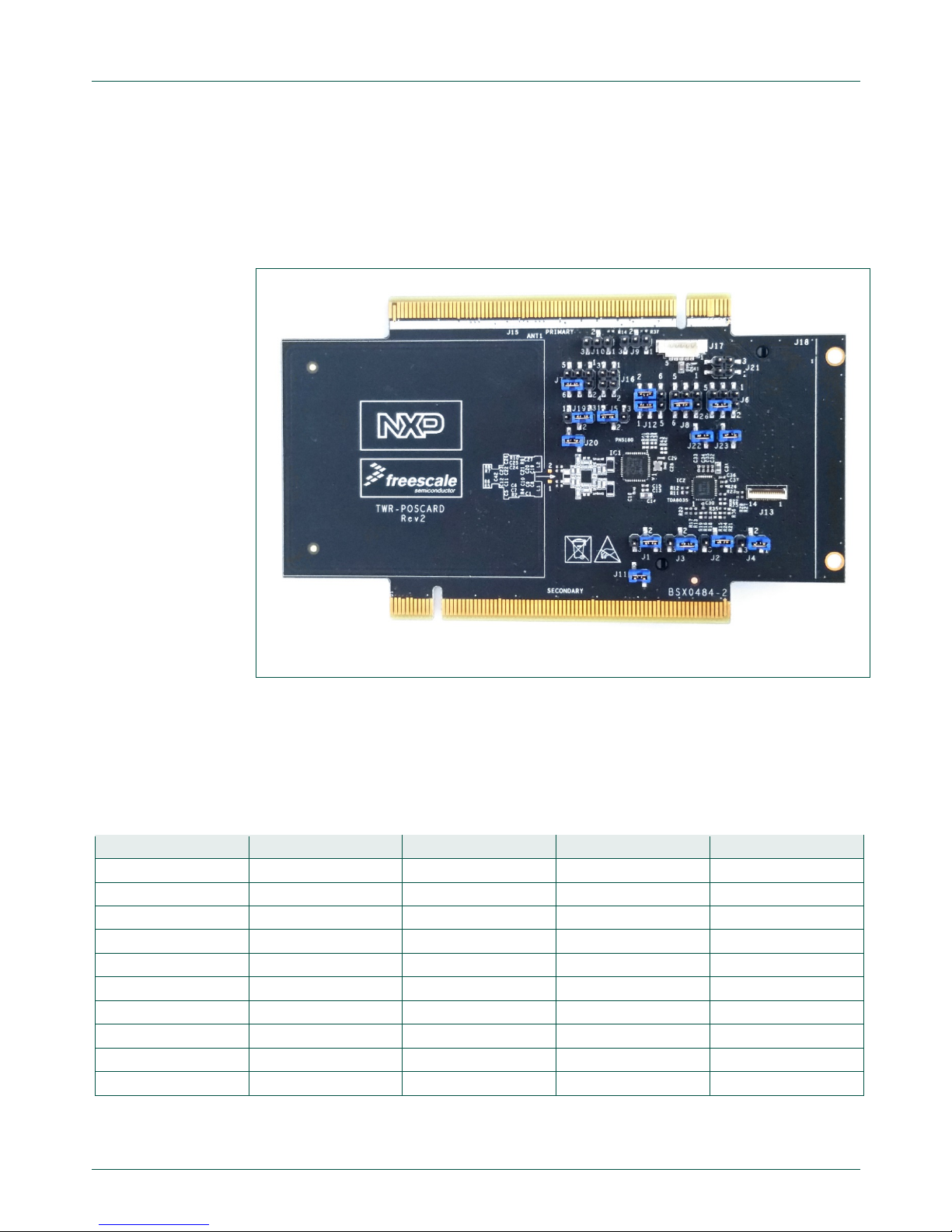
2.1.2 TWR-POS-PN5180
2.1.2.1 Presentation
This is the card interface board. It allows reading Contact and Contactless payment
cards. This board embeds NXP’s PN5180 (contactless frontend) and TDA8035 (contact
frontend)
Fig 4. TWR-POS-PN5180
2.1.2.2 Jumper settings
The jumpers on the TWR-POS-PN5180 are used to connect this board to different CPU
modules. The setting for these jumpers, to be used in this kit, is the one seen in Fig 4.
Below table gives the position of each jumper to be used in this RDR-POS-SLN:
Table 1. TWR-POS-PN5180 Jumper setting for RDR-POS-SLN
Jumper name
Setting
Jumper name
Setting
J1
1-2 J2
1-2
J3
1-2 J4
1-2
J5
1-2 J6
4-6
J7
4-6 J8
4-6
J9
Open
J10
Open
J11
1-2 J12 1-3-5
1-3
J12 2-4-6
2-4 J16 1-2
Open
J16 3-4
Open
J19
2-3
J20
1-2 J21
Open
J22
1-2 J23
1-2
Page 7
NXP Semiconductors
UM11036
Point of Sales (POS) Reader Solution - Quick Start Guide
UM11036
All information provided in this document is subject to legal disclaimers.
© NXP Semiconductors N.V. 2017. All rights reserved.
User manual
COMPANY PUBLIC
Rev. 1.2 — 7 February 2017
406512
7 of 56
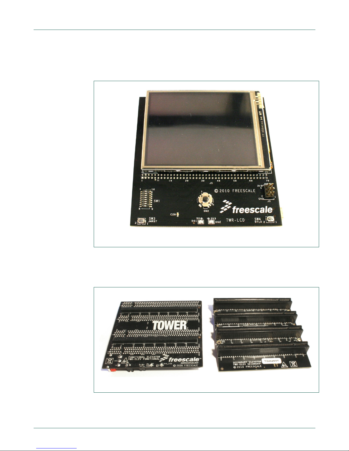
2.1.3 TWR-LCD
This is an LCD module board. This LCD touchscreen is used to interact with the user:
display information and get inputs from the user.
Fig 5. TWR-LCD
2.1.4 TWR-Elev
These are the connection boards. They are needed to connect all feature boards
together
Fig 6. TWR-Elev
Page 8
NXP Semiconductors
UM11036
Point of Sales (POS) Reader Solution - Quick Start Guide
UM11036
All information provided in this document is subject to legal disclaimers.
© NXP Semiconductors N.V. 2017. All rights reserved.
User manual
COMPANY PUBLIC
Rev. 1.2 — 7 February 2017
406512
8 of 56
2.1.5 Accessories
2.1.5.1 Cables
Two USB cables are provided: One USB Mini to provide power to the system, and one
USB Micro to interface with a computer
2.1.5.2 Battery
A CR2032 Button Cell battery is provided. The battery has to be inserte d in the battery
slot on the TWR-POS-K81 board
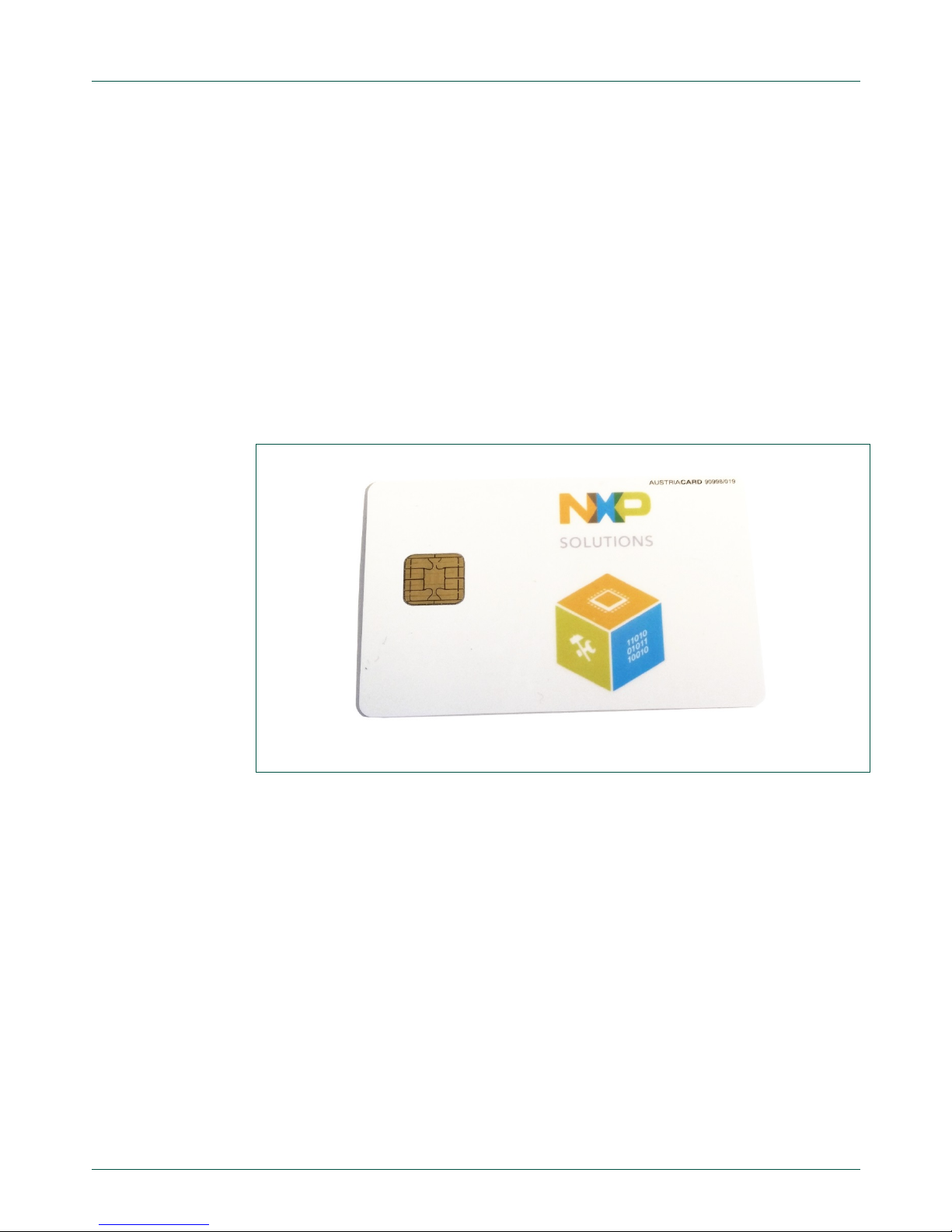
2.1.5.3 Sample Card
One sample card is included. It is a demo Payment card with dual interface (Contact +
Contactless). The card embeds a secure processor with JCOP OS, running a payment
application.
This payment application can be accessed through Contact or Contactless interface.
Fig 7. Sample card
2.2 Setup the kit
The kit is delivered already assembled, but in case it is received dis as sembled or is
disassembled during operation, the next chapters describe how to assemble it.
2.2.1 TWR-Elev Primary and Secondary boards
It is important for the next steps to differentiate the Primary and Secondary TWR-Elev
boards. Depending on the version, the name of the board can be written:
“Secondary board” or “Primary board” on the inner side (i.e the side with the 4 female
PCI connectors).
If the name is not printed on the board, the Primary can be found by its marking “A side
expansion port” and “B side expansion port”, while the Secondary board embeds “C side
expansion port” and “D side expansion port”
Page 9
NXP Semiconductors
UM11036
Point of Sales (POS) Reader Solution - Quick Start Guide
UM11036
All information provided in this document is subject to legal disclaimers.
© NXP Semiconductors N.V. 2017. All rights reserved.
User manual
COMPANY PUBLIC
Rev. 1.2 — 7 February 2017
406512
9 of 56
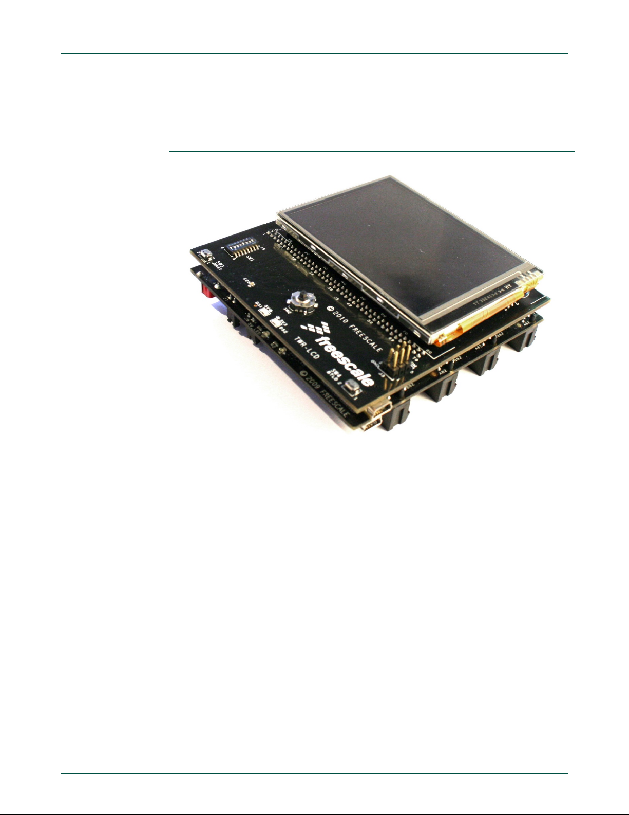
2.2.2 Assemble the Hardware
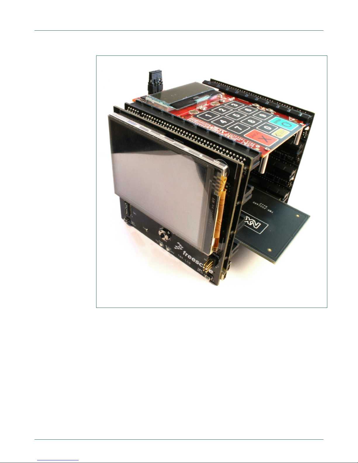
The TWR-LCD has to be connected on the outside of TWR-Elev Primary board.
Fig 8. TWR-LCD connected on TWR-Elev primary
TWR-POS-K81 and TWR-POS-PN5180 have to be connected in the TWR-Elev PCI
slots.
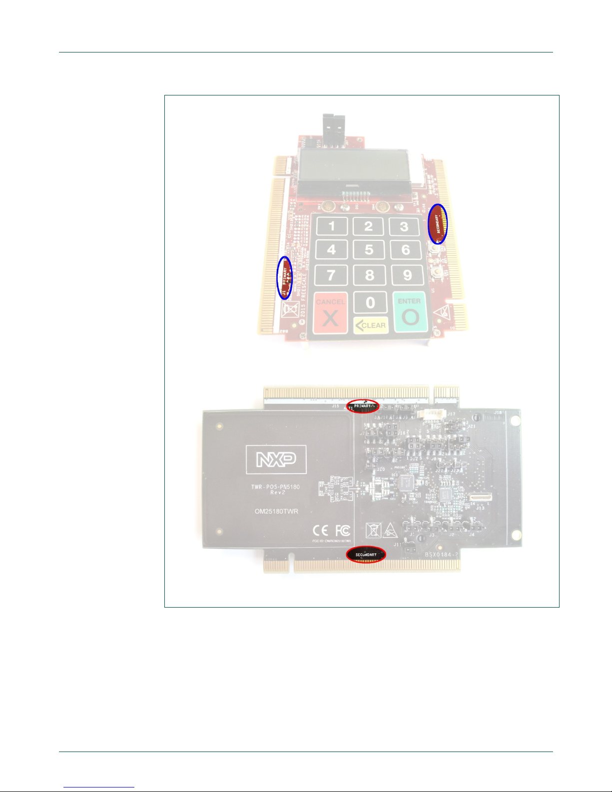
The primary and secondary connectors of each board have to be connected respectively
on the primary and secondary TWR-Elev boards. The side can be recognized by its
marking on each board as shown in Fig 9.
Page 10
NXP Semiconductors
UM11036
Point of Sales (POS) Reader Solution - Quick Start Guide
UM11036
All information provided in this document is subject to legal disclaimers.
© NXP Semiconductors N.V. 2017. All rights reserved.
User manual
COMPANY PUBLIC
Rev. 1.2 — 7 February 2017
406512
10 of 56
Fig 9. TWR-POS-K81 and TWR-POS-PN5180 sides
The most convenient way is to have the K81 board on the top connector, and the
PN5180 board on the bottom connector:
Page 11
NXP Semiconductors
UM11036
Point of Sales (POS) Reader Solution - Quick Start Guide
UM11036
All information provided in this document is subject to legal disclaimers.
© NXP Semiconductors N.V. 2017. All rights reserved.
User manual
COMPANY PUBLIC
Rev. 1.2 — 7 February 2017
406512
11 of 56
Fig 10. SLN-POS-RDR Hardware mounted
Page 12
NXP Semiconductors
UM11036
Point of Sales (POS) Reader Solution - Quick Start Guide
UM11036
All information provided in this document is subject to legal disclaimers.
© NXP Semiconductors N.V. 2017. All rights reserved.
User manual
COMPANY PUBLIC
Rev. 1.2 — 7 February 2017
406512
12 of 56
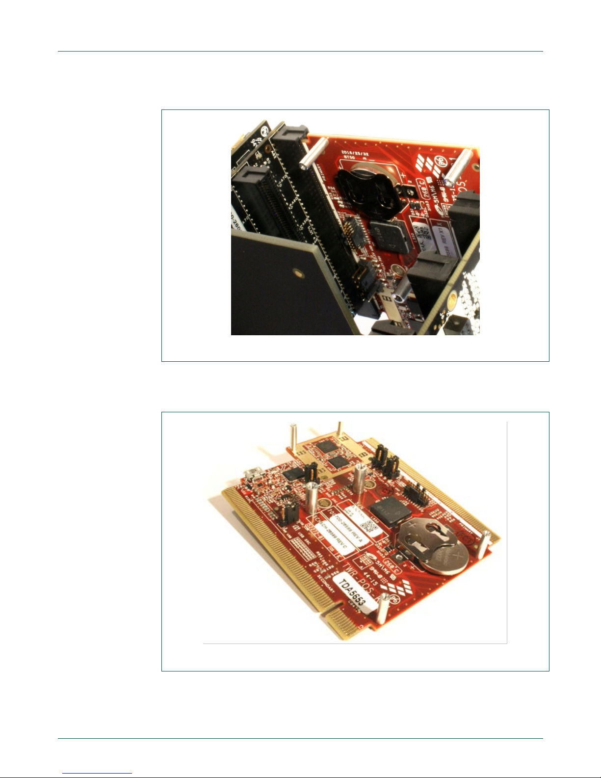
The battery has to be inserted in the battery slot, underneath the TWR-POS-K81 PCB:
Fig 11. Battery location
To insert the battery in the right way, the + symbol has to be on top (visible), as seen in
next figure:
Fig 12. Battery position
Page 13
NXP Semiconductors
UM11036
Point of Sales (POS) Reader Solution - Quick Start Guide
UM11036
All information provided in this document is subject to legal disclaimers.
© NXP Semiconductors N.V. 2017. All rights reserved.
User manual
COMPANY PUBLIC
Rev. 1.2 — 7 February 2017
406512
13 of 56
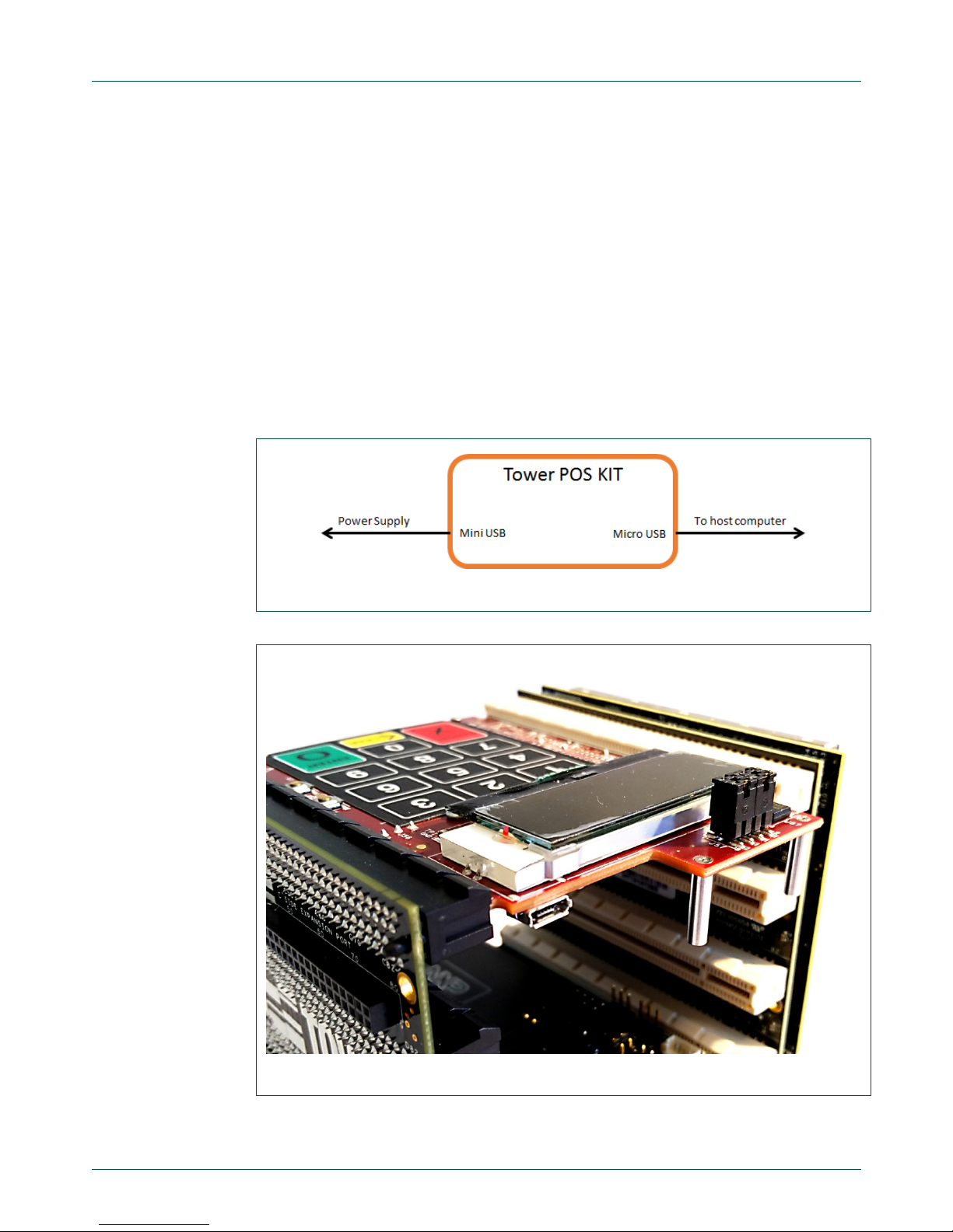
2.3 USB Connections
The Kit presents 3 USB connectors:
• One Mini USB on the TWR-Elev board
• One Mini USB on the TWR-LCD board
• One Micro USB on the TWR-POS-K81 board
See Fig 14 and Fig 15 for each connector’s location.
In order to operate the Tower Kit, both the Micro USB, underneath TWR-POS-K81 board,
and the Mini USB on the TWR-ELEV board have to be used.
Micro USB has to be connected to the host computer (running the high-lev el app lic atio n)
and the TWR-ELEV mini USB has to be connected to a power source (either from a
computer USB or from a power socket USB). Both are needed to ensure the Kit will have
enough power to operate in all modes.
Fig 13. Connections for demo operations
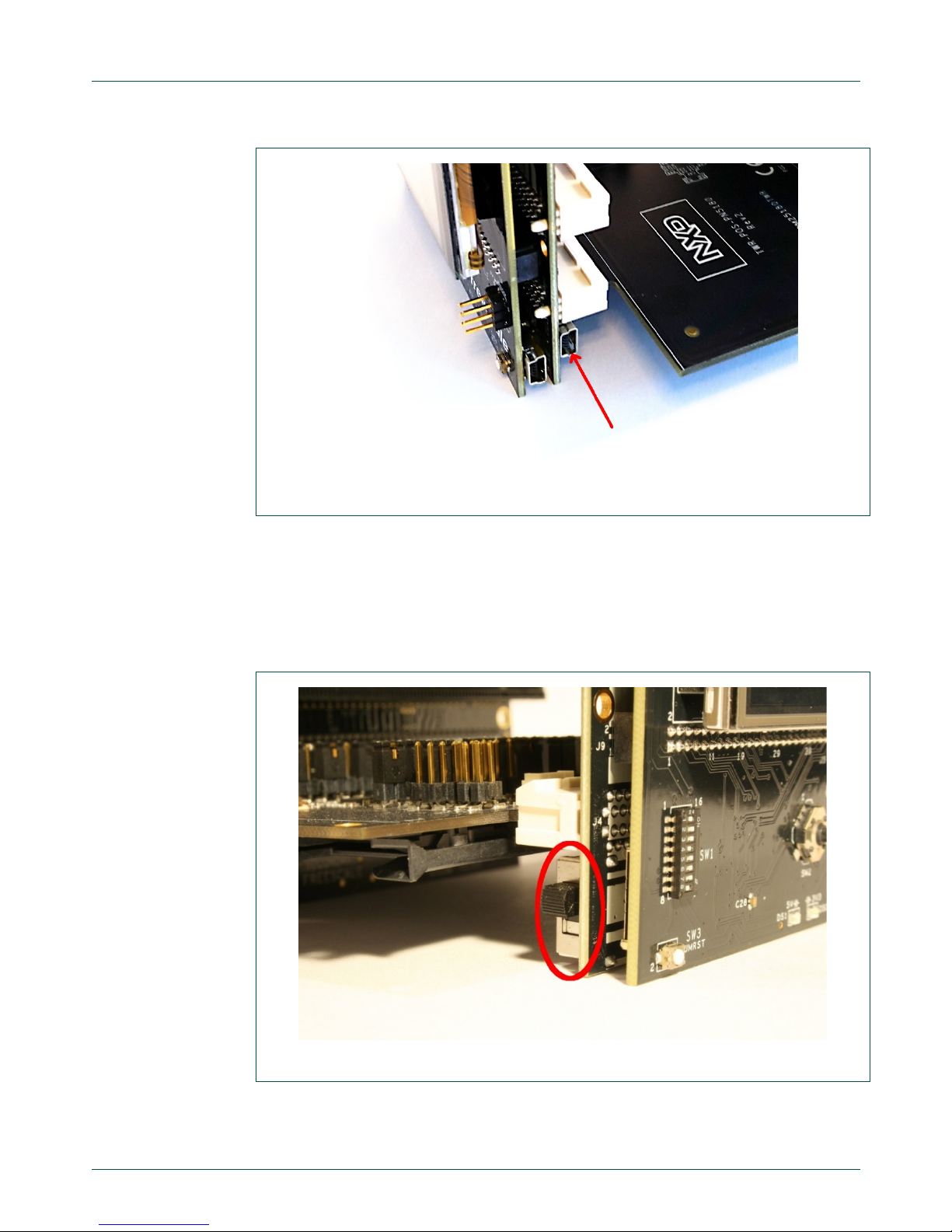
Fig 14. Connector location – Micro USB
Page 14
NXP Semiconductors
UM11036
Point of Sales (POS) Reader Solution - Quick Start Guide
UM11036
All information provided in this document is subject to legal disclaimers.
© NXP Semiconductors N.V. 2017. All rights reserved.
User manual
COMPANY PUBLIC
Rev. 1.2 — 7 February 2017
406512
14 of 56
Fig 15. Power supply connector location – Mini USB
2.4 TWR-ELEV Power Switch
A switch is mounted on the TWR-ELEV board. This switch is used to turn ON or OFF the
power supply from the TWR-ELEV USB connector.
For the SLN-POS-RDR to operate, the switch has to be in the ON position (top) shown in
Fig 16, otherwise there will be no power from this TWR-ELEV connector.
Fig 16. TWR-ELEV – Power switch ON position
Page 15

NXP Semiconductors
UM11036
Point of Sales (POS) Reader Solution - Quick Start Guide
UM11036
All information provided in this document is subject to legal disclaimers.
© NXP Semiconductors N.V. 2017. All rights reserved.
User manual
COMPANY PUBLIC
Rev. 1.2 — 7 February 2017
406512
15 of 56
3. Demonstration
3.1 Setup the environment
After the Hardware is assembled and connected, the computer has to be set up in order
to operate the payment demonstration: the TWR_POS_K81 module embeds a USB to
Serial converter, accessed through the mini USB port connected to the computer.
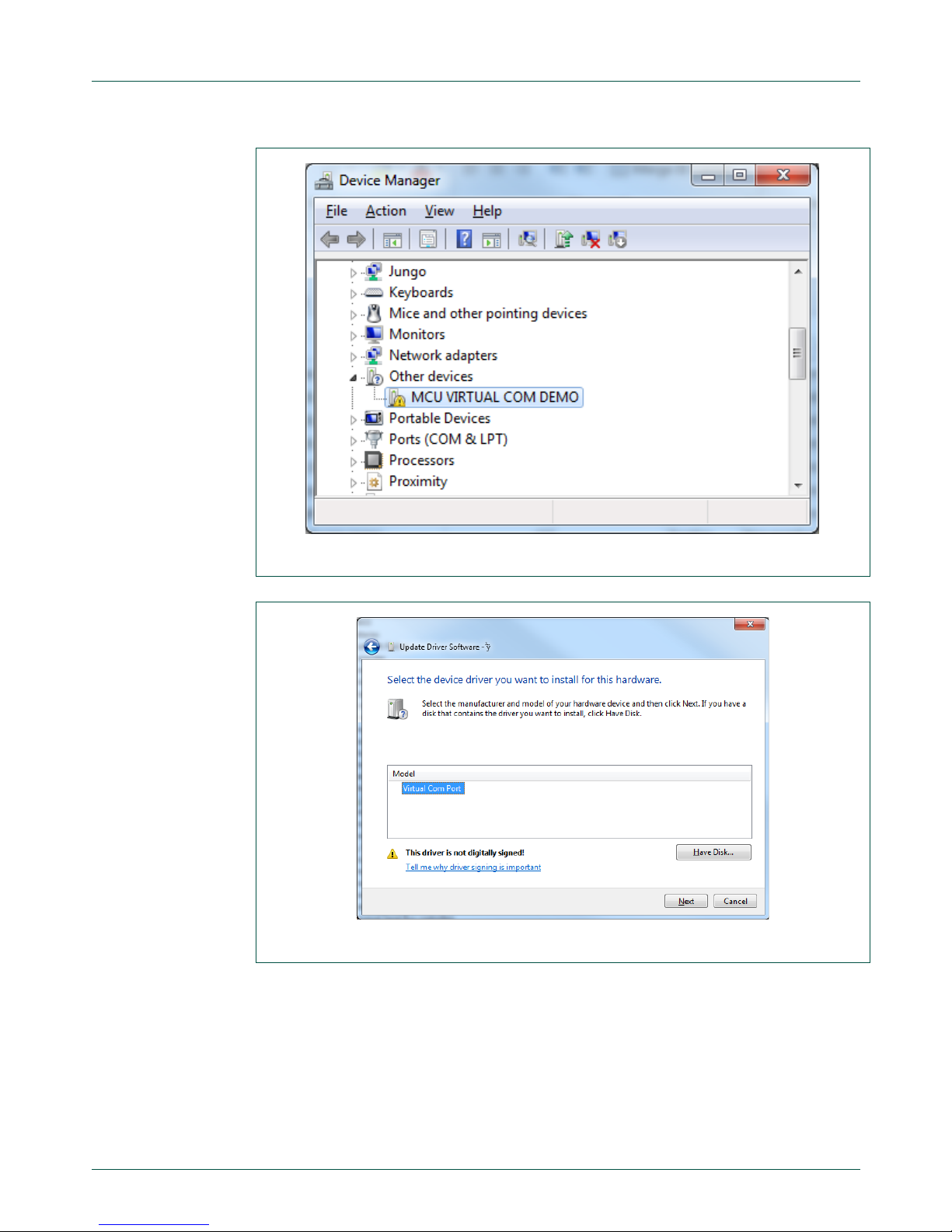
When this USB is connected, the host computer should display an unknown device in the
device manager.
The dedicated driver for this device has to be installed so that the computer gets a new
COM port that will be used to connect to the POS Reader Solution Kit. This can be done
following the below steps:
Locate the .inf file for this driver: It is delivered with the software package. It is called
fsl_ucwxp.inf and is located in the folder
“boards\twrposk81\demo_apps\payment_demo\cardtek_ihs_app”
Open the device manager
Locate the unknown device. This should be a device with a Yellow Bang, named
“MCU VIRTUAL COM DEMO”. See
Fig 17.
Right click on this device, and choose “Update Driver Software”
Select “Browse my computer for driver software”
“Let me pick from a list…”
“Show all devices” then “Next”
“Have Disk”
Click “Browse”, navigate to the folder containing the above mentioned .inf file, and
select this .inf file.
Windows should propose a Virtual COM port (see Fig 18). Select it then click “Next”
Note that Windows may show a warning saying that the driver is not digitally signed.
To install it anyway, the computer must be configured to disable driver signature
enforcement.
If the computer is not correctly configured, it can be done following Microsoft help.
E.g.
https://msdn.microsoft.com/en-us/windows/hardware/drivers/install/installing-an-
unsigned-driver-during-development-and-test
Note that the above link may not give the exact process depending on the computer
OS version.
Windows may then show some messages asking to confirm that you want to install
this driver. Accept by selecting “Install this driver Software anyway”
Windows will install the driver
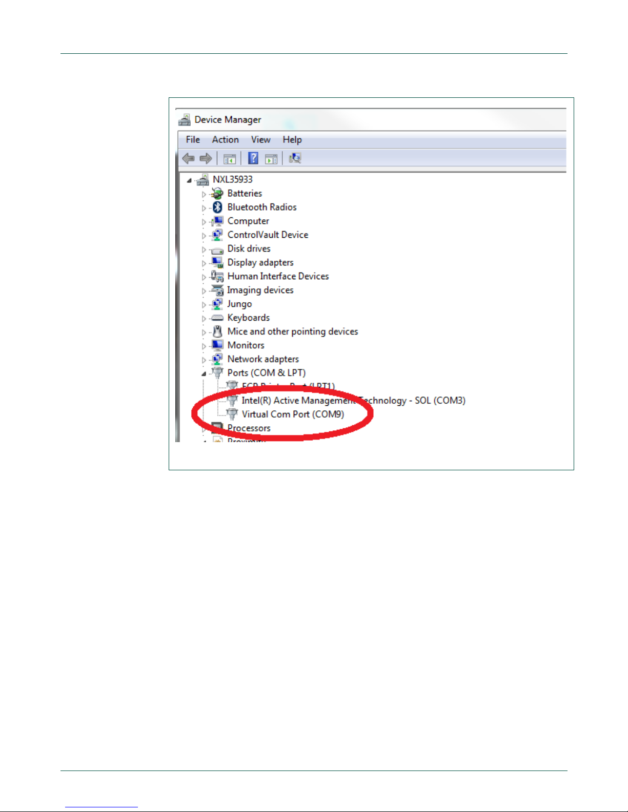
When the driver is installed, it may happen that Windows shows a message
informing that the driver cannot start. In such a case, unplug then plug back the USB
connection. This should restart the driver, so that it is seen as running (no error) in
the device manager (see
Fig 19).
Page 16
NXP Semiconductors
UM11036
Point of Sales (POS) Reader Solution - Quick Start Guide
UM11036
All information provided in this document is subject to legal disclaimers.
© NXP Semiconductors N.V. 2017. All rights reserved.
User manual
COMPANY PUBLIC
Rev. 1.2 — 7 February 2017
406512
16 of 56
Fig 17. Uninstalled COM port driver
Fig 18. Select proposed driver for Virtual COM port
Page 17
NXP Semiconductors
UM11036
Point of Sales (POS) Reader Solution - Quick Start Guide
UM11036
All information provided in this document is subject to legal disclaimers.
© NXP Semiconductors N.V. 2017. All rights reserved.
User manual
COMPANY PUBLIC
Rev. 1.2 — 7 February 2017
406512
17 of 56
Fig 19. Installed driver
Page 18

NXP Semiconductors
UM11036
Point of Sales (POS) Reader Solution - Quick Start Guide
UM11036
All information provided in this document is subject to legal disclaimers.
© NXP Semiconductors N.V. 2017. All rights reserved.
User manual
COMPANY PUBLIC
Rev. 1.2 — 7 February 2017
406512
18 of 56
3.2 First power-up of the kit
At first power-up, the POS-RDR-SLN kit will ask for a calibration of the side LCD screen.
This calibration requires the user to touch the screen at two specific locations.
To do so, touch the screen on the displayed crosses when prompted See Fig 20 and Fig
21.
Fig 20. LCD Screen - Calibration #1
Fig 21. LCD Screen - Calibration #2
Right after this operation, the LCD will display the demo screen. See next chapter.
Page 19

NXP Semiconductors
UM11036
Point of Sales (POS) Reader Solution - Quick Start Guide
UM11036
All information provided in this document is subject to legal disclaimers.
© NXP Semiconductors N.V. 2017. All rights reserved.
User manual
COMPANY PUBLIC
Rev. 1.2 — 7 February 2017
406512
19 of 56
3.3 Payment Demo application
This application demonstrates a full payment application using a sample payment card,
and an issuer payment application, running on the computer. This tool is called “Issuer
Host Simulator” (IHS).
The following chapters describe the way to use the default demonstration. For more
details, refer to [2].
3.3.1 Launch the demonstration
To start the demonstration:
Plug the POS Reader Kit Mini USB (power)
Plug the Micro USB to the computer (communication). Note the COM port value
assigned in the device manager.
Launch the Issuer Host Simulation (IHS) Tool that can be found in the SW release
package, in the folder
K81POSCR_SW_Release\boards\twrposk81\demo_apps\payment_demo\cardtek_ih
s_app
The tool is the application named “IHS.exe”.
Fig 22. Issuer Host Simulation tool window
In the COM Port configuration window, select the COM port value noted at step 2.
Page 20

NXP Semiconductors
UM11036
Point of Sales (POS) Reader Solution - Quick Start Guide
UM11036
All information provided in this document is subject to legal disclaimers.
© NXP Semiconductors N.V. 2017. All rights reserved.
User manual
COMPANY PUBLIC
Rev. 1.2 — 7 February 2017
406512
20 of 56
Click on “Connect”.
!! First time only !! – The first time the IHS is connected to the tool, it will download
some configuration files. Wait for this process to finish, then the demo can be used.
The TWR-ELEV LCD (color LCD) asks to pick an action: “Config” or “Payment”.
Fig 23. Demo start screen
Select “Payment” by touching the screen
The application asks to enter a transaction amount. This value has to be entered with
the secure pin pad on top of the solution. (e.g. 15.00 can be entered)
Page 21

NXP Semiconductors
UM11036
Point of Sales (POS) Reader Solution - Quick Start Guide
UM11036
All information provided in this document is subject to legal disclaimers.
© NXP Semiconductors N.V. 2017. All rights reserved.
User manual
COMPANY PUBLIC
Rev. 1.2 — 7 February 2017
406512
21 of 56
Fig 24. Enter amount screen
The amount is displayed on both LCD screen: on the TWR-POS-K81 2 lines LCD,
and on the side color LCD.
Fig 25. Pin pad - Enter amount
Page 22

NXP Semiconductors
UM11036
Point of Sales (POS) Reader Solution - Quick Start Guide
UM11036
All information provided in this document is subject to legal disclaimers.
© NXP Semiconductors N.V. 2017. All rights reserved.
User manual
COMPANY PUBLIC
Rev. 1.2 — 7 February 2017
406512
22 of 56
Press “Enter” on the secure pin pad to validate the amount.
The LCD screens ask to insert or tap a card. From this point, Contact or Contactless
transactions can be used. For contact transaction, go to step
13, and for contactless
operation, go to step 15.
Contact operation
a. Insert the sample card into the Contact Smart Card reader (located under the
TWR-POS-PN5180 module). The smart card has to be inserted with contacts and
prints on top:
Fig 26. Contact card insertion
b. The process continues and you are requested to enter the card PIN. Enter the 4
digits pin code on the TWR-POS-K81 module pin pad, then press Enter . The
default pin code is “1234”.
c. If the POS Reader Solution is connected to the IHS, and the IHS is active, the
LCD Screen will show “Online Approved – Remove Card”, and the transaction
information will be dis played in the IHS dedicated window.
Page 23

NXP Semiconductors
UM11036
Point of Sales (POS) Reader Solution - Quick Start Guide
UM11036
All information provided in this document is subject to legal disclaimers.
© NXP Semiconductors N.V. 2017. All rights reserved.
User manual
COMPANY PUBLIC
Rev. 1.2 — 7 February 2017
406512
23 of 56
Fig 27. Online approved
Fig 28. IHS - Transaction details
d. If the POS Reader Solution is not connected to the IHS, the LCD will display
“Offline Approved – Remove card”
Page 24

NXP Semiconductors
UM11036
Point of Sales (POS) Reader Solution - Quick Start Guide
UM11036
All information provided in this document is subject to legal disclaimers.
© NXP Semiconductors N.V. 2017. All rights reserved.
User manual
COMPANY PUBLIC
Rev. 1.2 — 7 February 2017
406512
24 of 56
Fig 29. Offline approved
You can now remove the card. The setup is ready for the next operation.
Contactless operation
a. When the POS asks to “Insert or Tap a Card”, the sample card can be tapped on
the TWR-POS-K81 board antenna:
Fig 30. Contactless card tap
Page 25

NXP Semiconductors
UM11036
Point of Sales (POS) Reader Solution - Quick Start Guide
UM11036
All information provided in this document is subject to legal disclaimers.
© NXP Semiconductors N.V. 2017. All rights reserved.
User manual
COMPANY PUBLIC
Rev. 1.2 — 7 February 2017
406512
25 of 56
b. This operation does not request a pin code to be entered. When the card is
detected, the transaction is processed and the POS displays “Offline Approved –
Remove Card”
Fig 31. Offline approved
Page 26

NXP Semiconductors
UM11036
Point of Sales (POS) Reader Solution - Quick Start Guide
UM11036
All information provided in this document is subject to legal disclaimers.
© NXP Semiconductors N.V. 2017. All rights reserved.
User manual
COMPANY PUBLIC
Rev. 1.2 — 7 February 2017
406512
26 of 56
3.4 Factory Reset
If the system needs to be set back to its default configuration, it is possible to reset it with
the factory settings.
To do so, at start-up screen, choose “Config”:
Fig 32. Factory reset #1
Then scroll down the configuration screen to display “Factory Reset”
Touch “Factory Reset” and then “OK”:
Fig 33. Factory reset #2
Page 27

NXP Semiconductors
UM11036
Point of Sales (POS) Reader Solution - Quick Start Guide
UM11036
All information provided in this document is subject to legal disclaimers.
© NXP Semiconductors N.V. 2017. All rights reserved.
User manual
COMPANY PUBLIC
Rev. 1.2 — 7 February 2017
406512
27 of 56
The system will reset its data internally. Several screens will be seen:
Fig 34. Factory reset #3
The process is finished when the screen shows back the “POS Config” menu screen. At
this point, the HW has to be reset: unplug the two USB cables, and plug them back.
The system will restart with the screen calibration. See 3.1.
Page 28

NXP Semiconductors
UM11036
Point of Sales (POS) Reader Solution - Quick Start Guide
UM11036
All information provided in this document is subject to legal disclaimers.
© NXP Semiconductors N.V. 2017. All rights reserved.
User manual
COMPANY PUBLIC
Rev. 1.2 — 7 February 2017
406512
28 of 56
4. POS Reader Solution Software
4.1 Introduction
The POS Reader Solution kit is delivered with a pre-installed software runni ng the
Payment Demo application.
The Software code can also be obtained directly from NXP. Contact your direct NXP
representative to get access to this software.
The software is delivered in a package containing source code from NXP and libraries
from third companies.
The folder tree from this SW code delivery is as follows:
Fig 35. Software Delivery – Folder tree
The “boards” folder contains the demonstration example projects that are prepared for
two IDEs (Integrated Development Environment): IAR and KDS.
Other folders contain source code and libraries for all embedded features.
For deeper details about the SW content, refer to [1].
Page 29

NXP Semiconductors
UM11036
Point of Sales (POS) Reader Solution - Quick Start Guide
UM11036
All information provided in this document is subject to legal disclaimers.
© NXP Semiconductors N.V. 2017. All rights reserved.
User manual
COMPANY PUBLIC
Rev. 1.2 — 7 February 2017
406512
29 of 56
4.2 Software project
To open the software project, edit, compile and load the Software into K81 target, 2 IDEs
can be used: IAR and KDS.
4.2.1 Debug Probe – J-Link
The program download into the K81 requires a J-Link probe to be connected between
the computer and the K81 target.
J-Link probe is used for this purpose and can as well be used to debug the program
running in the K81 target. This connection requires at a minimum a J-Link Base probe,
and a 19-pin Cortex-M Adapter, to connect the probe to the K81 module:
https://www.segger.com/jlink_base.html
https://www.segger.com/jlink-adapters-19pin-cortexm.html
Probe drivers should be automatically installed during the installation of the IDE.
The probe and the adapter are not part of the kit. They have to be purchased
separately.
The first time the probe is used, its driver has to be installed. Driver and instructions can
be found under JLINK website: choose the “J-Link Software and Documentation
Pack” download:
https://www.segger.com/downloads/jlink
4.2.2 Debug information (printf)
Some debug information can be received through UART, using a Serial board extension.
Fig 36. TWR-SER
This board is not part of the kit, but can be purchased directly from NXP:
TWR-SER NXP Web page
Page 30

NXP Semiconductors
UM11036
Point of Sales (POS) Reader Solution - Quick Start Guide
UM11036
All information provided in this document is subject to legal disclaimers.
© NXP Semiconductors N.V. 2017. All rights reserved.
User manual
COMPANY PUBLIC
Rev. 1.2 — 7 February 2017
406512
30 of 56
In order to use this board and display the printf messages from the software, the TWRSER module has to be inserted in the POS-RDR-SLN Kit. As for the other modules, the
primary and secondary interfaces have to match the right side of the TWR-ELEV boards.
Fig 37. TWR-SER in the POS-RDR-SLN Kit
Once inserted, the Serial port seen in F ig 37 has to be connected to a computer COM
port. On the computer, open a COM port terminal, with a speed of 115200 bps, and the
data will be displayed as the software runs.
Page 31

NXP Semiconductors
UM11036
Point of Sales (POS) Reader Solution - Quick Start Guide
UM11036
All information provided in this document is subject to legal disclaimers.
© NXP Semiconductors N.V. 2017. All rights reserved.
User manual
COMPANY PUBLIC
Rev. 1.2 — 7 February 2017
406512
31 of 56
4.2.3 Using IAR
This chapter describes how to open and run the project Payment Application Demo.
IAR must be pre-installed with a valid license before going through these steps.
The minimum required IAR version is 7.70.0 .
4.2.3.1 Open the project and compile
1. Locate the .eww file from the demo project folder:
K81POSCR_SW_Release\boards\twrposk81\demo_apps\payment_demo\iar
2. Double click on the .eww file. It will open the project in IAR.
Alternatively, if the .eww files are not linked to IAR, the following step have to be done.
Otherwise, jump to step 6.
3. Open IAR
4. Select File>Open>Project and browse to the folder containing the IAR project file
(extension is .eww).
5. Select the file payment_demo.eww
The project contains two subprojects: Payment_demo and lib_pos:
Fig 38. Payment Demo project tree
The Payment_demo project is the main application. It requires the lib_pos library
to compile.
The compilation must then start with this lib_pos project.
6. Right click on the lib_pos project, and select Make
Page 32

NXP Semiconductors
UM11036
Point of Sales (POS) Reader Solution - Quick Start Guide
UM11036
All information provided in this document is subject to legal disclaimers.
© NXP Semiconductors N.V. 2017. All rights reserved.
User manual
COMPANY PUBLIC
Rev. 1.2 — 7 February 2017
406512
32 of 56
Fig 39. Start compiling – lib_pos
7. Once the lib_pos library is compiled, a library lib_pos.a must be found in
K81POSCR_SW_Release\boards\twrposk81\demo_apps\payment_demo\iar\lib_
pos\debug (if debug configuration mode is used)
8. Build the Payment_demo app by right-clicking on the payment_demo solution,
and choosing “Make”.
9. The software is now built a nd can be loaded into the P O S Reader So lut ion K8 1
target.
Page 33

NXP Semiconductors
UM11036
Point of Sales (POS) Reader Solution - Quick Start Guide
UM11036
All information provided in this document is subject to legal disclaimers.
© NXP Semiconductors N.V. 2017. All rights reserved.
User manual
COMPANY PUBLIC
Rev. 1.2 — 7 February 2017
406512
33 of 56
4.2.3.2 Download Software
Downloading Software requires the J-Link probe to be connected to the computer over
USB, and to the TWR-POS-K81 module, through the 19-pin Adapter. See Fig 40.
Fig 40. J-Link probe connections
The J-Link probe has to be connected to the connector shown in Fig 41.
Fig 41. J-Link connector location on TWR-POS-K81 bottom side
Page 34

NXP Semiconductors
UM11036
Point of Sales (POS) Reader Solution - Quick Start Guide
UM11036
All information provided in this document is subject to legal disclaimers.
© NXP Semiconductors N.V. 2017. All rights reserved.
User manual
COMPANY PUBLIC
Rev. 1.2 — 7 February 2017
406512
34 of 56
With the probe connected and the kit powered, select Project >Download>Download
Active Application in IAR.
Note: The K81 must be powered to perform this application.
Fig 42. IAR Download application
Page 35

NXP Semiconductors
UM11036
Point of Sales (POS) Reader Solution - Quick Start Guide
UM11036
All information provided in this document is subject to legal disclaimers.
© NXP Semiconductors N.V. 2017. All rights reserved.
User manual
COMPANY PUBLIC
Rev. 1.2 — 7 February 2017
406512
35 of 56
4.2.3.3 Debug Software
To run the software in debug mode, the same J-Link probe can be used with the same
connection.
To start the debug mode, simply click the debug button or select Project>Download and
Debug:
Fig 43. IAR Launch debug mode
Page 36

NXP Semiconductors
UM11036
Point of Sales (POS) Reader Solution - Quick Start Guide
UM11036
All information provided in this document is subject to legal disclaimers.
© NXP Semiconductors N.V. 2017. All rights reserved.
User manual
COMPANY PUBLIC
Rev. 1.2 — 7 February 2017
406512
36 of 56
4.2.4 Using KDS
4.2.4.1 Install and start KDS
KDS (Kinetis Design Studio) has to be installed first. The KDS installation can be found
from NXP website:
www.nxp.com/products/software-and-tools/run-time-software/kinetis-software-andtools/ides-for-kinetis-mcus/kinetis-design-studio-integrated-development-environmentide:KDS_IDE
The minimum required KDS version is 3.2.0.
Once KDS is installed, launch the application. KDS first asks to select a folder that will
become the Workspace for this KDS session.
Select any folder on the local disk. It doesn’t have to contain data at first.
Remember the folder location: next time KDS will be open, this workspace will have to be
selected to retrieve the ongoing projects. The workspace will not necessarily contain
source code, but it will contain all configuration and information about current projects.
Fig 44. Select KDS Workspace
When the workspace path is selected, KDS opens with its welcome information page:
Page 37

NXP Semiconductors
UM11036
Point of Sales (POS) Reader Solution - Quick Start Guide
UM11036
All information provided in this document is subject to legal disclaimers.
© NXP Semiconductors N.V. 2017. All rights reserved.
User manual
COMPANY PUBLIC
Rev. 1.2 — 7 February 2017
406512
37 of 56
Fig 45. KDS Welcome page
Close this page, and KDS will show its default view:
Fig 46. KDS default view – No project
Page 38

NXP Semiconductors
UM11036
Point of Sales (POS) Reader Solution - Quick Start Guide
UM11036
All information provided in this document is subject to legal disclaimers.
© NXP Semiconductors N.V. 2017. All rights reserved.
User manual
COMPANY PUBLIC
Rev. 1.2 — 7 February 2017
406512
38 of 56
4.2.4.2 Import the project and compile
From here, the Payment_demo application project can be imported, following below
steps:
Select in the menu: File>Import
In the ‘Import’ Window, select ‘General’, then ‘Existing Project into Workspace’
Fig 47. Import Project
Click ‘Next’
Check ‘Select root directory’, and Browse to the following folder (or enter the path to
the following folder in the path field:
K81POSCR_SW_Release\boards\twrposk81\demo_apps\payment_demo\kds
Then press ‘Enter’. The existing projects will be shown in the below windo w:
Page 39

NXP Semiconductors
UM11036
Point of Sales (POS) Reader Solution - Quick Start Guide
UM11036
All information provided in this document is subject to legal disclaimers.
© NXP Semiconductors N.V. 2017. All rights reserved.
User manual
COMPANY PUBLIC
Rev. 1.2 — 7 February 2017
406512
39 of 56
Fig 48. Projects to import from payment-demo application
Select the two projects (payment_demo and lib_pos), make sure the option boxes
are not checked, and click Finish.
Projects are now imported
Page 40

NXP Semiconductors
UM11036
Point of Sales (POS) Reader Solution - Quick Start Guide
UM11036
All information provided in this document is subject to legal disclaimers.
© NXP Semiconductors N.V. 2017. All rights reserved.
User manual
COMPANY PUBLIC
Rev. 1.2 — 7 February 2017
406512
40 of 56
Fig 49. Projects imported
Projects can now be compiled: Right click on ‘lib_pos’ projects in the left panel, and
select ‘build’
Fig 50. Build lib_pos
Page 41

NXP Semiconductors
UM11036
Point of Sales (POS) Reader Solution - Quick Start Guide
UM11036
All information provided in this document is subject to legal disclaimers.
© NXP Semiconductors N.V. 2017. All rights reserved.
User manual
COMPANY PUBLIC
Rev. 1.2 — 7 February 2017
406512
41 of 56
When the build is completed, do the same with the payment_demo project.
Note that the compilation order is important: lib_pos is a library which is needed by the
payment_demo application. If the payment_demo application project is compiled first, the
compilation may fail, or the project wouldn’t include the latest changes from lib_pos.
Once both builds are done, the full project is compiled and ready to use.
4.2.4.3 Download Software and debug
Downloading Software requires the J-Link probe to be connected to the computer over
USB, and to the TWR-POS-K81 module, through the 19-pin Adapter. See Fig 51.
Fig 51. J-Link probe connections
The J-Link probe has to be connected to the connector shown in Fig 41.
Page 42

NXP Semiconductors
UM11036
Point of Sales (POS) Reader Solution - Quick Start Guide
UM11036
All information provided in this document is subject to legal disclaimers.
© NXP Semiconductors N.V. 2017. All rights reserved.
User manual
COMPANY PUBLIC
Rev. 1.2 — 7 February 2017
406512
42 of 56
Note: The K81 must be powered to perform this application.
To download the software through the debug mode, open the debug configurations menu
by clicking the little bug in the menu bar and selecting “Debug Configurations…”:
Fig 52. Open ‘Debug configurations’ menu
Page 43

NXP Semiconductors
UM11036
Point of Sales (POS) Reader Solution - Quick Start Guide
UM11036
All information provided in this document is subject to legal disclaimers.
© NXP Semiconductors N.V. 2017. All rights reserved.
User manual
COMPANY PUBLIC
Rev. 1.2 — 7 February 2017
406512
43 of 56
In the menu, select “payment_demo_twrposk81 debug jlink”, and click debug:
Fig 53. Start debug mode
The software will be loaded into K81 through the J-Link probe, and KDS will change its
perspective to the debug view.
Press the F8 key to launch the program, or press F5 to run step by step.
Page 44

NXP Semiconductors
UM11036
Point of Sales (POS) Reader Solution - Quick Start Guide
UM11036
All information provided in this document is subject to legal disclaimers.
© NXP Semiconductors N.V. 2017. All rights reserved.
User manual
COMPANY PUBLIC
Rev. 1.2 — 7 February 2017
406512
44 of 56
4.3 PN5180 Firmware update procedure
4.3.1 Introduction
The TWR-POS-PN5180 board includes a contactless reader device which embeds a
controller and its own Firmware for contactless operations.
In some cases, this FW has to be upgraded – For instance when a new EMVCo
specification has to be supported.
This chapter describes the PN5180 secure firmware update application. Application
allows customer to update PN5180 firmware to the latest firmware version.
pn5180_firmware_update will check the onboard PN5180 firmware and notifies the user
to update to the latest version if needed. Hardware modifications are required only for
existing/legacy TWR-POS boards already in the field to perform firmware update which
will be described in detail in the further sections.
4.3.2 Secure Firmware Update Flow Diagram
The next figure shows the PN5180 secure FW update application flow.
Page 45

NXP Semiconductors
UM11036
Point of Sales (POS) Reader Solution - Quick Start Guide
UM11036
All information provided in this document is subject to legal disclaimers.
© NXP Semiconductors N.V. 2017. All rights reserved.
User manual
COMPANY PUBLIC
Rev. 1.2 — 7 February 2017
406512
45 of 56
Fig 54. PN5180 Firmware update – Block diagram
The above block diagram shows the pn5180_firmware_update application flow. Firmware
version of onboard PN5180 is compared with the latest firmware version which is
available for download. If firmware versions are the same, graphic LCD is updated with a
UI message saying that “PN5180 already updated” and stops the application. If firmware
versions are not the same, prints a UI message "Update Firmware version X.X to Y.Y?"
(Whereas X.X is current version and Y.Y is the version to update to). In case user
confirms by pressing “OK” on graphic LCD then application performs PN5180 firmware
update and prints out status message like “Update successful” or “Update Failed!!!”.
Display “PN5180
already updated”
Check FW
== Y.Y
latest
version
STOP
Display “PN5180
FW check failed”
Get current
Firmware
Version
Update
PN5180 to
FW Ver Y.Y
START
Display “Update
Successful.”
Display “Update
Failed!!!.”
Update
Firmware
version X.X
Page 46

NXP Semiconductors
UM11036
Point of Sales (POS) Reader Solution - Quick Start Guide
UM11036
All information provided in this document is subject to legal disclaimers.
© NXP Semiconductors N.V. 2017. All rights reserved.
User manual
COMPANY PUBLIC
Rev. 1.2 — 7 February 2017
406512
46 of 56
4.4 Hardware Modifications
Chapters 4.4.1 and 4.4.2 describe board modifications on TWR-POS-PN5180 and TWRPOS-K81 boards allowing download of PN5180 Firmware.
POS kits delivered after 8 February 2017 already include these changes.
4.4.1 TWR-POS-PN5180 Board Modification
Current TWR-POS-PN5180 board includes NC (Non Connected) R41 as shown in below
schematic. Add 0 Ohm resistor in place of “R41 NC”. See the below board image to
identify the R41 resistor placing.
Fig 55. R41 on schematics
Fig 56. R41 location
Page 47

NXP Semiconductors
UM11036
Point of Sales (POS) Reader Solution - Quick Start Guide
UM11036
All information provided in this document is subject to legal disclaimers.
© NXP Semiconductors N.V. 2017. All rights reserved.
User manual
COMPANY PUBLIC
Rev. 1.2 — 7 February 2017
406512
47 of 56
4.4.2 K81 Mother Board Modification
Current K81 mother board includes R12 DNP as shown in the snap below.
Fig 57. R12 on schematics
Fig 58. R12 location
Page 48

NXP Semiconductors
UM11036
Point of Sales (POS) Reader Solution - Quick Start Guide
UM11036
All information provided in this document is subject to legal disclaimers.
© NXP Semiconductors N.V. 2017. All rights reserved.
User manual
COMPANY PUBLIC
Rev. 1.2 — 7 February 2017
406512
48 of 56
4.5 PN5180 firmware update
4.5.1 PN5180 Latest Firmware update
Make sure the two mandatory hardware changes are done as mentioned above before
downloading pn5180_f irm w are_u pdat e appl ic at ion int o the board.
The “demo_apps” folder contains the pn5180_firmware_update example project that is
prepared for two IDEs: IAR and KDS. Build and load the application into the board with
the chosen IDE.
For more details on how to build and load the project, refer to section 4.2.3 for IAR or
4.2.4 for KDS. The only difference is the name of the main project: replace
“payment_demo” by “secure_fw_update”.
Upon executing pn5180_fir mware_update will check the current firmware version in
PN5180.
If the current version is already latest, then no more action required and graphic LCD
is displayed with “PN5180 already updated”.
If the current version is NOT latest, then graphic LCD is displayed with “Update
Firmware version X.X to Y.Y?”.
Fig 59. Firmware update screen
Press “OK” to update PN5180.
Page 49

NXP Semiconductors
UM11036
Point of Sales (POS) Reader Solution - Quick Start Guide
UM11036
All information provided in this document is subject to legal disclaimers.
© NXP Semiconductors N.V. 2017. All rights reserved.
User manual
COMPANY PUBLIC
Rev. 1.2 — 7 February 2017
406512
49 of 56
PN5180 will be updated to the latest 3.9 version and “Update Successful” is displayed
on graphic LCD.
Fig 60. “Update Successful” message
Restarting the board again should result in “PN5180 already updated”
Fig 61. “Already updated” message
Page 50

NXP Semiconductors
UM11036
Point of Sales (POS) Reader Solution - Quick Start Guide
UM11036
All information provided in this document is subject to legal disclaimers.
© NXP Semiconductors N.V. 2017. All rights reserved.
User manual
COMPANY PUBLIC
Rev. 1.2 — 7 February 2017
406512
50 of 56
4.6 Add New PN5180 firmware version
4.6.1 Adding new PN5180 firmware to pn5180_firmware_update
Minor changes are required to add a new PN5180 firmware version support in
pn5180_firmware_update application. The “demo_apps” folder contains the
pn5180_firmware_update example project that is prepared for two IDEs: IAR and KDS.
1. Add PN5180 FW_Y_Y.h header file to the pn5180_firmware_update project with
the chosen IDE, similar to the image shown below for FW_3_6.h, FW_3_8.h &
FW_3_9.h versions.
Fig 62. KDS & IAR – Firmware file tree
2. Include the FW_Y_Y.h in pn5180_firmware_update_app.c as indicate below.
KDS IDE
IAR IDE
Page 51

NXP Semiconductors
UM11036
Point of Sales (POS) Reader Solution - Quick Start Guide
UM11036
All information provided in this document is subject to legal disclaimers.
© NXP Semiconductors N.V. 2017. All rights reserved.
User manual
COMPANY PUBLIC
Rev. 1.2 — 7 February 2017
406512
51 of 56
Fig 63. .h file include
3. Add a macro define for the new firmware version in pn5180_firmware_update.h,
similar macro defines are shown below.
Fig 64. Add macro define
If the firmware version is Y.Y assign macro value as 0xYY for example if the version is
4.0 then assign macro value as 0x40.
Include here
Page 52

NXP Semiconductors
UM11036
Point of Sales (POS) Reader Solution - Quick Start Guide
UM11036
All information provided in this document is subject to legal disclaimers.
© NXP Semiconductors N.V. 2017. All rights reserved.
User manual
COMPANY PUBLIC
Rev. 1.2 — 7 February 2017
406512
52 of 56
4. Assign the defined macro to PN5180_FW_VER in pn5180_firmware_update.h
file similar to the image shown below.
Fig 65. Assign the new FW version
5. PN5180 new firmware header file FW_Y_Y.h wi ll cont ain an ar ra y and its length.
Assign array to PN5180_FW_VER_BIN_ARRAY macro and the length variable
to PN5180_FW_VER_BIN_LEN in pn5180_firmware_update.h file as shown
below.
Fig 66. Assign pointer and length
By this all the changes are done, build the lib_pos and pn5180_firmware_update projects
and load the application into the board. To update PN5180 firmware to latest Y.Y version
please refer to section 4.5 (PN5180 firmware update).
Page 53

NXP Semiconductors
UM11036
Point of Sales (POS) Reader Solution - Quick Start Guide
UM11036
All information provided in this document is subject to legal disclaimers.
© NXP Semiconductors N.V. 2017. All rights reserved.
User manual
COMPANY PUBLIC
Rev. 1.2 — 7 February 2017
406512
53 of 56
5. References
[1] K81 POS Card Reader Solution User's Guide.pdf
[2] L2 Kernel Card Profiles and Demo Scenarios 21102016 v2.4.pdf
Page 54

NXP Semiconductors
UM11036
Point of Sales (POS) Reader Solution - Quick Start Guide
UM11036
All information provided in this docum ent is subject to legal disclaimers.
© NXP Semiconductors N.V. 2017. All rights reserved.
User manual
COMPANY PUBLIC
Rev. 1.2 — 7 February 2017
406512
54 of 56
6. Legal information
6.1 Definitions
Draft — The document is a draft version only. The content is still under
internal review and subject to formal approval, which may result in
modifications or additions. NXP Semiconductors does not give any
representations or war ra nti e s as to th e accu racy or completeness of
information included herein and shall have no liability for the consequences
of use of such information.
6.2 Disclaimers
Limited warranty and liability — Information in this document is believed to
be accurate and reliable. However, NXP Semiconductors does not give any
representations or war ra nti e s, expressed or implied, as to the accuracy or
completeness of such information and shall have no liability for the
consequences of use of such information. NXP Semiconductors takes no
responsibility for the content in this document if provided by an information
source outside of NXP Semiconductors.
In no event shall NXP Semiconductors be liable for any indirect, incidental,
punitive, special or consequential damages (including - without limitation lost profits, lost savings, business interruption, costs related to the removal or
replacement of any produc ts or rework charges) whether or not such
damages are based on tort (includin g n egligence), warranty, brea ch of
contract or any other legal theory.
Notwithstanding any damages that customer might incur for any reason
whatsoever, NXP Semiconductors’ aggregate and cumulative liability
towards customer for the products describe d herein shall be limited in
accordance with the Terms and conditions of commercial sale of NXP
Semiconductors.
Right to make changes — NXP Semiconductors reserves the right to make
changes to information published in this document, including without
limitation specifica ti on s and pr od uct de scri pti ons, at any time and without
notice. This document supersedes and replaces all information supplied prior
to the publication hereof .
Suitability for use — NXP Semiconductors products are not designed,
authorized or warranted to be suitable for use in life support, life-critical or
safety-critical systems or equipment, nor in applications where failure or
malfunction of an NXP Semiconductors product can reasonably be expected
to result in personal injury, death or severe property or environmental
damage. NXP Semiconductors and its suppliers accept no liability for
inclusion and/or use of NXP Semiconductors products in such equipment or
applications and therefore such inclusion and/or use is at the customer’s
own risk.
Applications — Applications that are described herein for an y of these
products are for illustrative purposes only. NXP Semiconductors makes no
representation or war ra nt y that such ap pl icat i ons will be suitable for the
specified use without further testing or modification.
Customers are responsible for the design and operation of their applications
and products using NXP Semiconductors products, and NXP
Semiconductors acc ept s no liabi li t y for any assistance with applications or
customer product design. It is customer’s sole responsibility to determine
whether the NXP Semiconductors product is suitable and fit for the
customer’s applications and products planned, as well as for the planned
application and use of customer’s thir d par t y customer(s). Customers should
provide appropriate design and operating safeguards to minimize the risks
associated with their applications and products.
NXP Semiconductors does not accept any liability related to any default,
damage, costs or problem whic h is bas ed on an y weak n ess or def ault in the
customer’s applications or products, or the application or use by customer’s
third party customer(s). Customer is responsible for doing all necessary
testing for the customer’s applications and products using NXP
Semiconductors prod uc ts i n ord er to av oid a def a ult of t he ap plic ati ons and
the products or of the application or use by customer’s third party
customer(s). NXP does not accept any liability in this respect.
Export control — This document as well as the item(s) described herein
may be subject to export control regulations. Export might require a prior
authorization from competent authorities.
Translations — A non-English (translated) version of a document is for
reference only. The English version shall prevail in case of any discrepancy
between the translated and English versions.
Evaluation pr o du ct s — This product is provided on an “as is” and “with all
faults” basis for evaluati o n pur pos es only. NXP Semiconductors, its affiliates
and their suppliers expressly disclaim all warranties, whether express,
implied or statutory, including but not limited to the implied warranties of noninfringement, merchantability and fitness for a particular purpose. The entire
risk as to the quality, or arising out of the use or performance, of this product
remains with customer.
In no event shall NXP Semiconductors, its affiliates or their suppliers be
liable to customer for any special, indirect, consequential, punitive or
incidental damages (including without limitation damages for loss of
business, business interruption, loss of use, loss of data or information, and
the like) arising out the use of or inability to use the product, whether or not
based on tort (including negligence), strict liability, breach of contract, breach
of warran ty or any other theory, even if advised of the possi bil it y of suc h
damages.
Notwithstanding any damages that customer might incur for any reason
whatsoever (including without limitation, all damages referenced above and
all direct or general damages), the entire liability of NXP Semiconductors, its
affiliates and their suppli e rs and customer’s exclusive remedy for all of the
foregoing shall be limited to actual damages incurred by customer based on
reasonable reliance up to the greater of the amount actually paid by
customer for the product or five dollars (US$5.00). The foregoing limitations,
exclusions and disclaimers shall apply to the maximum extent permitted by
applicable law, even if any remedy fails of its essential purpose.
6.3 Trademarks
Notice: All referenced brands, product names, service names and
trademarks are property of their respective owners.
Page 55

NXP Semiconductors
UM11036
Point of Sales (POS) Reader Solution - Quick Start Guide
UM11036
All information provided in this document is subject to legal disclaimers.
© NXP Semiconductors N.V. 2017. All rights reserved.
User manual
COMPANY PUBLIC
Rev. 1.2 — 7 February 2017
406512
55 of 56
7. List of figures
Fig 1. POS Reader Solution Kit box ............................ 3
Fig 2. Kit Content ........................................................ 4
Fig 3. TWR-POS-K81 ................................................. 5
Fig 4. TWR-POS-PN5180 ........................................... 6
Fig 5. TWR-LCD ......................................................... 7
Fig 6. TWR-Elev.......................................................... 7
Fig 7. Sample card ...................................................... 8
Fig 8. TWR-LCD connected on TWR-Elev primary ..... 9
Fig 9. TWR-POS-K81 and TWR-POS-PN5180 sides10
Fig 10. SLN-POS-RDR Hardware mounted ................ 11
Fig 11. Battery location ............................................... 12
Fig 12. Battery position ............................................... 12
Fig 13. Connections for demo operations ................... 13
Fig 14. Connector location – Micro USB ..................... 13
Fig 15. Power supply connector location – Mini USB .. 14
Fig 16. TWR-ELEV – Power switch ON position ......... 14
Fig 17. Uninstalled COM port driver ............................ 16
Fig 18. Select proposed driver for Virtual COM port ... 16
Fig 19. Installed driver ................................................. 17
Fig 20. LCD Screen - Calibration #1 ........................... 18
Fig 21. LCD Screen - Calibration #2 ........................... 18
Fig 22. Issuer Host Simulation tool window ................ 19
Fig 23. Demo start screen ........................................... 20
Fig 24. Enter amount screen ....................................... 21
Fig 25. Pin pad - Enter amount ................................... 21
Fig 26. Contact card insertion ..................................... 22
Fig 27. Online approved .............................................. 23
Fig 28. IHS - Transaction details ................................. 23
Fig 29. Offline approved .............................................. 24
Fig 30. Contactless card tap ....................................... 24
Fig 31. Offline approved .............................................. 25
Fig 32. Factory reset #1 .............................................. 26
Fig 33. Factory reset #2 .............................................. 26
Fig 34. Factory reset #3 .............................................. 27
Fig 35. Software Delivery – Folder tree ....................... 28
Fig 36. TWR-SER ....................................................... 29
Fig 37. TWR-SER in the POS-RDR-SLN Kit ............... 30
Fig 38. Payment Demo project tree ............................ 31
Fig 39. Start compiling – lib_pos ................................. 32
Fig 40. J-Link probe connections ................................ 33
Fig 41. J-Link connector location on TWR-POS-K81
bottom side ..................................................... 33
Fig 42. IAR Download application ............................... 34
Fig 43. IAR Launch debug mode................................. 35
Fig 44. Select KDS Workspace ................................... 36
Fig 45. KDS Welcome page ........................................ 37
Fig 46. KDS default view – No project ......................... 37
Fig 47. Import Project .................................................. 38
Fig 48. Projects to import from payment-demo
application ....................................................... 39
Fig 49. Projects imported ............................................ 40
Fig 50. Build lib_pos .................................................... 40
Fig 51. J-Link probe connections ................................ 41
Fig 52. Open ‘Debug configurations’ menu ................. 42
Fig 53. Start debug mode ............................................ 43
Fig 54. PN5180 Firmware update – Block diagram ..... 45
Fig 55. R41 on schematics .......................................... 46
Fig 56. R41 location .................................................... 46
Fig 57. R12 on schematics .......................................... 47
Fig 58. R12 location .................................................... 47
Fig 59. Firmware update screen.................................. 48
Fig 60. “Update Successful” message ........................ 49
Fig 61. “Already updated” message ............................ 49
Fig 62. KDS & IAR – Firmware file tree ....................... 50
Fig 63. .h file include ................................................... 51
Fig 64. Add macro define ............................................ 51
Fig 65. Assign the new FW version ............................. 52
Fig 66. Assign pointer and length ................................ 52
Page 56

NXP Semiconductors
UM11036
Point of Sales (POS) Reader Solution - Quick Start Guide
Please
be aware that important notices concerning this document and the product(s)
described herein, have been included in the section 'Legal information'.
©
NXP Semiconductors N.V. 2017. All rights reserved.
For more information, please visit: http://www.nxp.com
Date of release:
7 February 2017 406512
Document identifier:
UM11036
8. Contents
1. Introduction ......................................................... 3
2. POS Reader Solution kit ..................................... 4
2.1 Kit Content ......................................................... 4
2.1.1 TWR-POS-K81 ................................................... 5
2.1.2 TWR-POS-PN5180 ............................................ 6
2.1.2.1 Presentation ....................................................... 6
2.1.2.2 Jumper settings .................................................. 6
2.1.3 TWR-LCD........................................................... 7
2.1.4 TWR-Elev ........................................................... 7
2.1.5 Accessories ........................................................ 8
2.1.5.1 Cables ................................................................ 8
2.1.5.2 Battery ................................................................ 8
2.1.5.3 Sample Card ...................................................... 8
2.2 Setup the kit ....................................................... 8
2.2.1 TWR-Elev Primary and Secondary boards......... 8
2.2.2 Assemble the Hardware ..................................... 9
2.3 USB Connections ............................................. 13
2.4 TWR-ELEV Power Switch ................................ 14
3. Demonstration ................................................... 15
3.1 Setup the environment ..................................... 15
3.2 First power-up of the kit .................................... 18
3.3 Payment Demo application .............................. 19
3.3.1 Launch the demonstration ................................ 19
3.4 Factory Reset ................................................... 26
4. POS Reader Solution Software ........................ 28
4.1 Introduction ...................................................... 28
4.2 Software project ............................................... 29
4.2.1 Debug Probe – J-Link ...................................... 29
4.2.2 Debug information (printf)................................. 29
4.2.3 Using IAR ......................................................... 31
4.2.3.1 Open the project and compile .......................... 31
4.2.3.2 Download Software .......................................... 33
4.2.3.3 Debug Software ............................................... 35
4.2.4 Using KDS........................................................ 36
4.2.4.1 Install and start KDS ........................................ 36
4.2.4.2 Import the project and compile ......................... 38
4.2.4.3 Download Software and debug ........................ 41
4.3 PN5180 Firmware update procedure ............... 44
4.3.1 Introduction ....................................................... 44
4.3.2 Secure Firmware Update Flow Diagram........... 44
4.4 Hardware Modifications .................................... 46
4.4.1 TWR-POS-PN5180 Board Modification ............ 46
4.4.2 K81 Mother Board Modification ........................ 47
4.5 PN5180 firmware update .................................. 48
4.5.1 PN5180 Latest Firmware update ...................... 48
4.6 Add New PN5180 firmware version .................. 50
4.6.1 Adding new PN5180 firmware to
pn5180_firmware_update ................................. 50
5. References ......................................................... 53
6. Legal information .............................................. 54
6.1 Definitions ......................................................... 54
6.2 Disclaimers ....................................................... 54
6.3 Trademarks ...................................................... 54
7. List of figures ..................................................... 55
8. Contents ............................................................. 56
 Loading...