

Page 1
Getting Started with NXP's LPC11XX Cortex-M0 ARM
Microcontrollers
Introduction
Hardware
Software
Code Example 0: Toggle a GPIO Pin
Code Example 1: Read a GPIO Pin
Code Example 2: Setting Up the Oscillator
Code Example 3: Transmitting Data Using the UART
Code Example 4: Receiving Data Using the UART
Code Example 5: Using the Analog to Digital Converter (ADC)
Code Example 6: Transmitting with Synchronous Serial Port (SSP/SPI)
Code Example 7: Setting Up the 16bit Timer for PWM
Code Example 8: Transmitting with I2C
Author's Note:
Introduction
Many engineers use 8 bit microcontrollers because of their low cost and ease of use. 32 bit microcontrollers generally offer higher performance
than 8 bit parts, but many believe their cost is significantly higher than bit uCs and that they are more difficult to use than 8 bit parts. While 32 bit
parts are generally a little more complicated than 8 bit parts, the cost of 8 and 32 bit parts aren’t that far apart in many cases. Additionally, the 32
bit parts offer significantly higher performance. In other words, give 32 bit parts a chance!
NXP has introduced a very low cost (i.e. often less than $1 in production volumes) line of 32 bit microcontrollers, the LPC111X family. There are
several other companies also offering some type of ARM Cortex M0 microcontroller. NXP was one of the earliest, but Freescale (Kinetis L), ST
Micro (STM32 F0), and Nuvoton (M051,M058,Mini51,NUC100,NUC122) also have Cortex M0 offerings. This document will give a brief
introduction on how to get up and running using NXP's . The code will work on several other members of the LPC11xx family as well. LPC1114
The assumption inherent in this document is that most engineers follow a fairly similar method of learning when presented with a new
microcontroller family. They start by getting a development kit and trying to toggle a pin, transmit/receive with a serial port, read an ADC pin
etc. This document will show some very simple examples of how to enable and operate these peripherals. This will not be exhaustive of every
operating mode and every peripheral but, it is hoped that it will cover the basics in sufficient detail to allow an engineer to get up and running
quickly. Also included are some tips regarding custom design of PCBs using these parts (see example schematic and BOM below in the
"Hardware" section.
This document is primarily targeted at those who are familiar with 8 bit microcontrollers, but are interested in learning to use a 32 bit part. It is
hoped that this document can make getting started with a 32 bit part as painless as possible. It is realized that this code is very simplistic, and if
one were going to write production code, there would certainly be other features, such as error checking, that would be needed. This code is
provided purely to provide a simplistic “working” example.
Page 2
Hardware
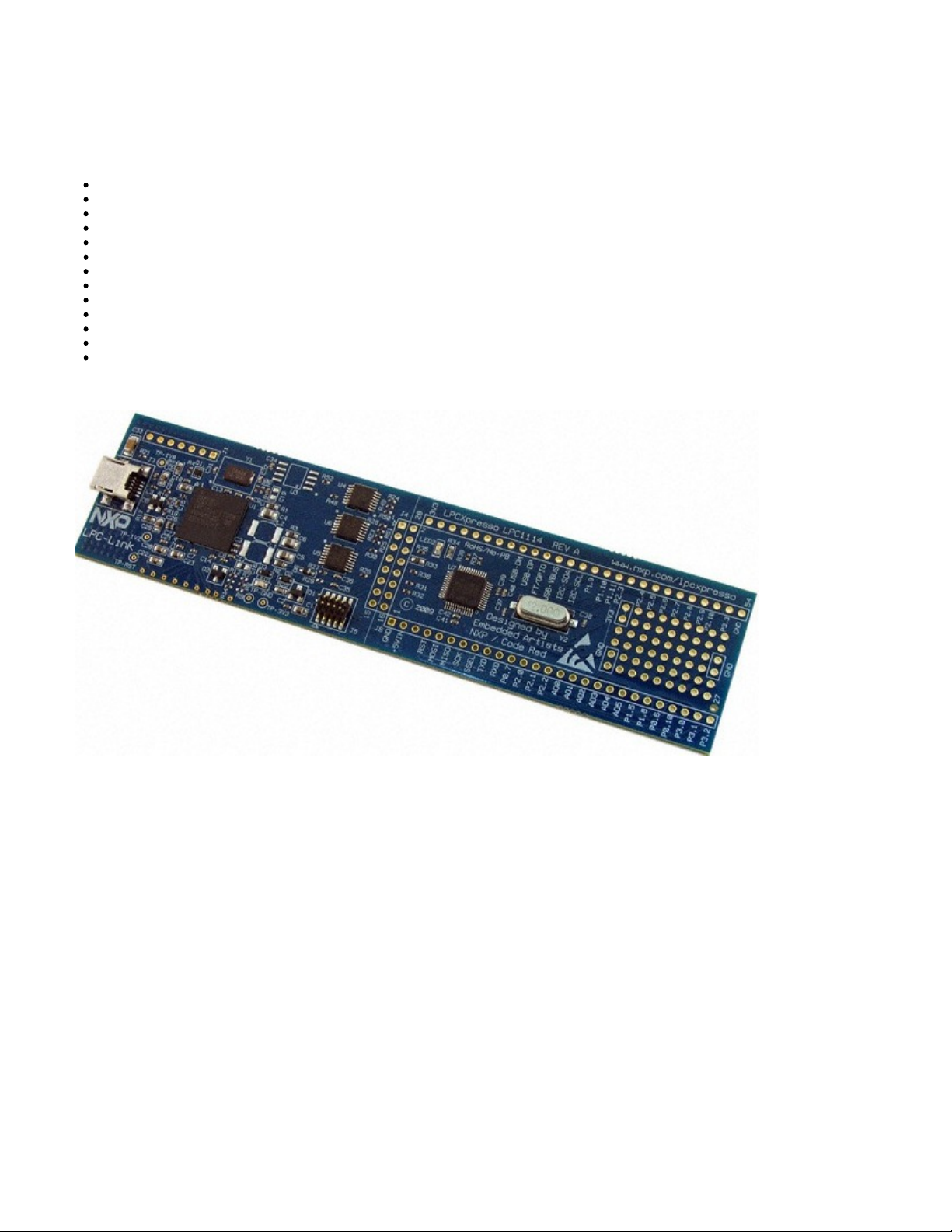
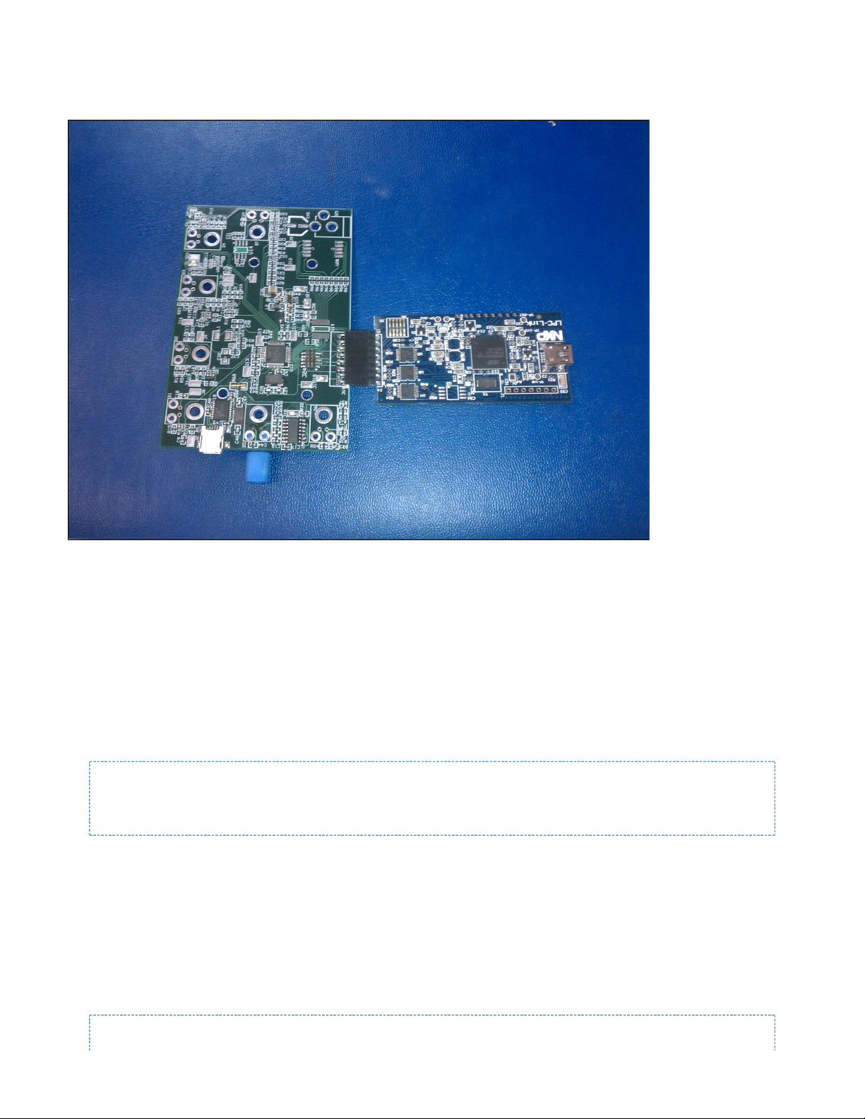
The examples described in this document will be run on Embedded Artists’ (shown at the top of this wiki page). It should be noted EA-XPR-002
that from Embedded Artists is identical to from NXP. So the two part numbers can be used interchangeably. This EA-XPR-002 OM11049,598
document generally refers to , but that is just for convenience. Any example given in this document should work on both boards EA-XPR-002
using the Code Red Software (discussed below). This PCB can be used standalone, plugged into a solderless , or it can be plugged breadboard
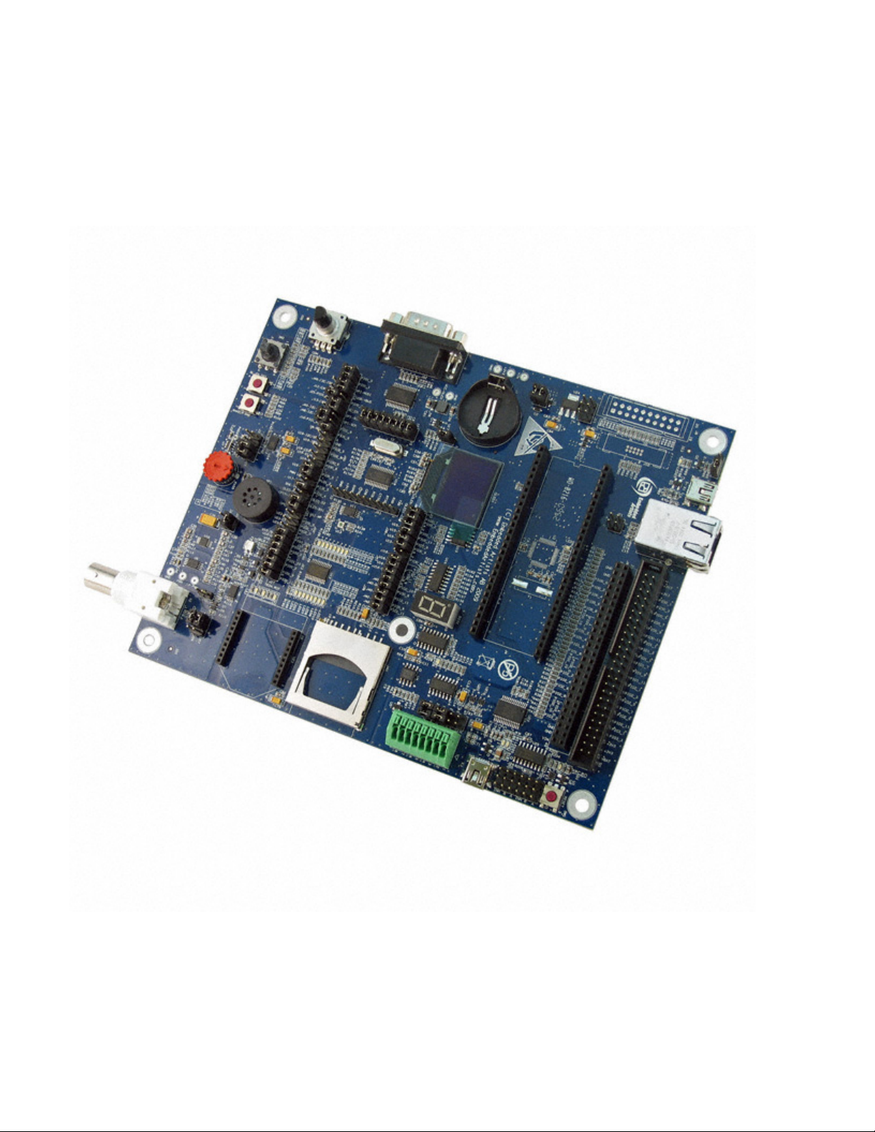
into a dedicated base board such as (shown in Figure 1 below). The or the plugs in on top of this EA-XPR-021 EA-XPR-002 OM11049,598
baseboard and allows you to use the peripherals of the in an easily measurable/observable way. Since this page was first built NXP LPC1114
purchased Embedded Artists and has obsoleted the . So just use the OM11049,598. All the examples should work exactly the EA-XPR-002
same.
NXP's Figure 1: EA-XPR-021
If the (or any other LPC111X device) is being designed into a custom board here are a couple examples of how to connect the part to LPC1114
the programming header (plus part numbers). This circuit was built and successfully tested with the parts indicated.
Page 3
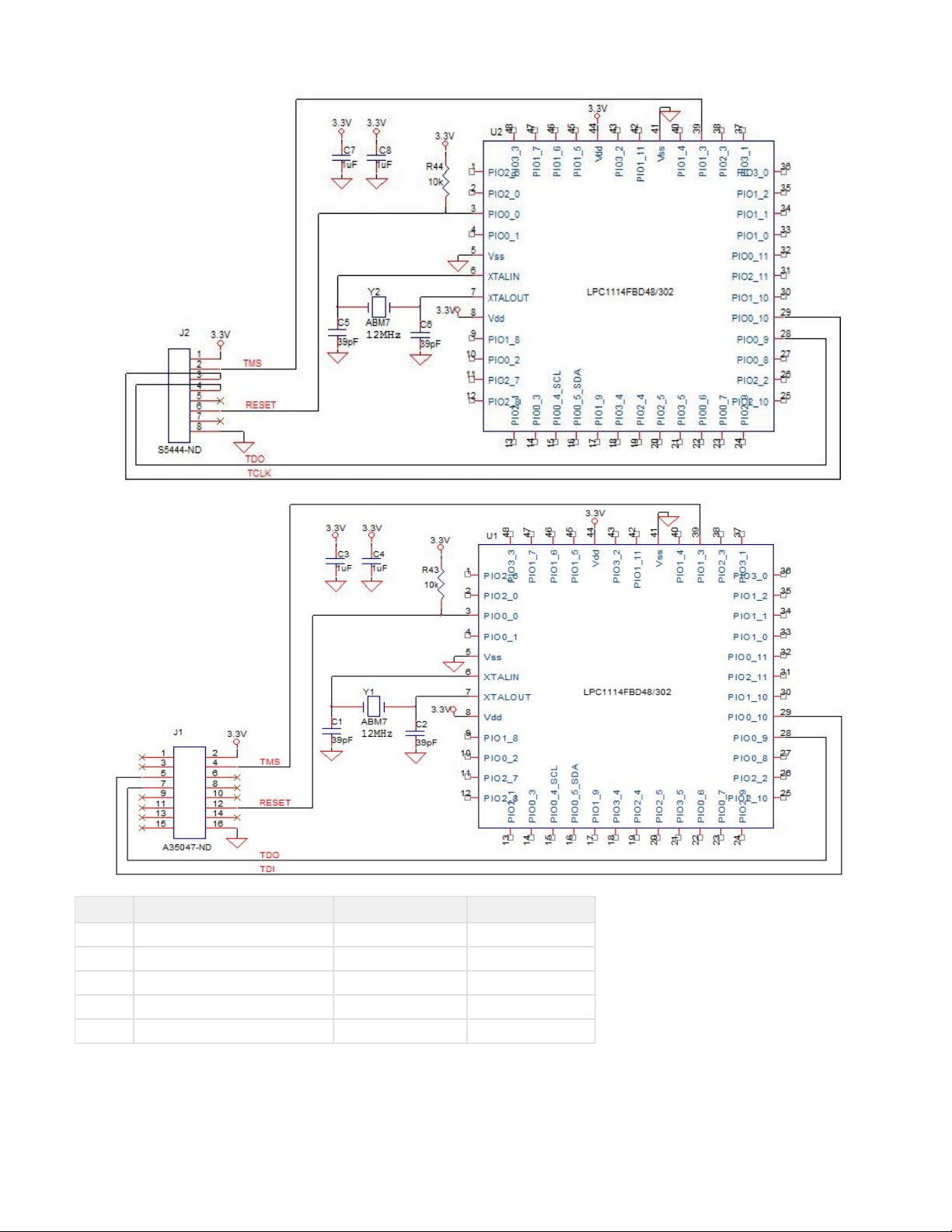
Ref Des Part Number Digi-Key Part Number Other Options
U1 LPC1114FBD48/302,1 (NXP) 568-5150-ND
J1 534237-6 (TE Connectivity) A26420-ND S5444-ND, A35047-ND
Y1 ABM7-12.000MHZ-D-2-Y-T (Abracon) 535-9836-1-ND
39pF GRM1885C1H390JA01D (Murata) 490-1417-1-ND
1uF EMK107B7105KA-T (Taiyo Yuden) 587-1241-1-ND
Figure 2: Here here are some examples of basic circuits that can be used to get the up and running on a custom board. It should be LC1114
noted that the connector, J1, has the pins on the left and right side shorted together so 1 and 2 are shorted together as are 3 and 4 etc. The
connector, , has the advantage of being very securely attached to the PCB. Other connector options are shown as well. A possible 5535676-7
Page 4
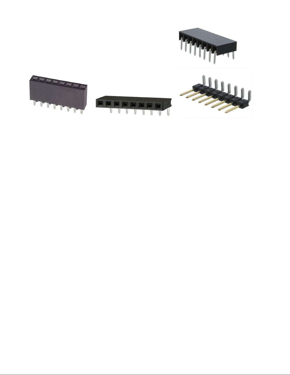
mating connector for the three connectors given/shown above is from 3M 961108-5604-AR
Figure 3: (TE Connectivity), (TE Connectivity), (Sullins), and (3M) respectively5535676-7 534237-6 PPTC081LGBN-RC 961108-5604-AR
Page 5

Figure 4
Above (figure 3) is a pictorial example of how the can be used as an inexpensive programmer/debugger. The OM11049,598 OM11049,598
board can be carefully split in two using a “Dremel” tool, at least that’s how separation was accomplished in this case. Wear safety
glasses! Alternatively, I was told by an NXP applications engineer that some customers have found that an old style paper cutter (see Figure 4)
Page 6
works very well too. If you don't like the idea of cutting the board, the can be used without physically splitting the PCB in two. To OM11049,598
prepare for use without sawing it in half, use an “exacto” knife to cut the traces between the two rows of vias that compose J4. Then solder a
vertical connector into the vias on the programmer/debugger side.
Figure 5: Here a split is used as a programmer/debugger with a custom PCB. In this case, is the connector on OM11049,598 961108-5604-AR
the programmer/debugger and is the mating connector on the custom PCB.PPTC081LGBN-RC
Software
All software examples were written in the C programming language using LPCXpresso v4.1.5 [12/12/2011] development system. This
development environment is available free of charge at ; The comments in the code http://www.support.code-red-tech.com/CodeRedWiki
examples that have a parenthetical note such as (sec 3.5.14) refer to the NXP's "UM10398 LPC11x/LPC11Cxx User Manual" Rev. 12 - 24
September 2012
Important Note: Many of the software examples below write to a register with a name that begins with "LPC_IOCON...". All of these code
samples have been tested and run on real hardware. However on another custom circuit board the author found that in order to successfully
modify these registers the following piece of code had to be included:
LPC_SYSCON->SYSAHBCLKCTRL |= (1<<16); //enable the clock to the
IOCON block (section 3.5.14)
So if one of the code examples shown here doesn't function correctly. Check and see if one of the "LPC_IOCON..." registers are being
modified. If so, add the line of code above before trying to write to an "LPC_IOCON..." register and see if that fixes the problem. The author
found this to be the solution to a problem experienced when using pin PIO1_1 (pin 34 on the 48 pin QFP part). The pin wouldn't toggle until the
line above was added enabling the clock to the IOCON register. So keep this in mind when using the examples here.
Code Example 0: Toggle a GPIO Pin
This code snippet shows a simple program that was compiled and run on the LPCXpresso board successfully. The program toggles pin 23 on
and off within the infinite while loop. Pin 23 will turn the boards lone LED on and off. For more examples of this type click or (for a plain here here
text file).
Page 7

#include "LPC11xx.h"
int main(void) { //Toggle a GPIO (FBD48 pin 23, PIO0_7, controls the
LED on the LPC Expresso PCB)
LPC_SYSCON->SYSAHBCLKCTRL |= (1<<6); //enable clock GPIO (sec
3.5.14)
LPC_IOCON->PIO0_7 &= ~(0x10); //NOT REQUIRED, turn off
pull up (sec 7.4.19)
LPC_GPIO0->DIR |= (1<<7); //set pin direction to
output (sec 12.3.2)
unsigned int i = 0;
while(1){ //infinite loop
LPC_GPIO0->DATA |= (1<<7); //set pin high (sec
12.3.1)
for(i=0; i<0xFFFFF; ++i); //arbitrary delay
LPC_GPIO0->DATA &= ~(1<<7); //set pin low (sec
12.3.1)
for(i=0; i<0xFFFFF; ++i); //arbitrary delay
}
return 0 ;
}
Important Note: The LPC1114 toggles pins rather slowly. If you set the oscillator to a frequency of 48MHz and comment out the two "for" loops
you’ll find that this program will only toggle a pin at around 1MHz. It’s something to be aware of if you are planning to toggle pins in a timing
critical application. Some other NXP chips such the LPC13xx, LPC17xx, LPC23xx, LPC8xx, and some members of the LPC21xx family have
“fast GPIO” that will toggle much faster than the LPC111X parts.
Code Example 1: Read a GPIO Pin
This program reads pin 40 (PIO1_4/AD5) and toggles pin 23 in response to pin 40s state. If pin 40 is high, the pin 23 is set high and vice
versa. Recall that on the board pin 23 is attached to an LED. This LED turns on when pin 23 is high. For more examples of OM11049,598
reading pins as general purpose inputs click . Note that pin 40 is labelled as "AD5" on the PCB since it serves dual function here OM11049,598
as an analog to digital converter input if configured differently.
\#include "LPC11xx.h"
int main(void) {
//Toggle a pin 23 in response to digital voltage change on pin 40
LPC_SYSCON->SYSAHBCLKCTRL |= (1<<6); //enable clock GPIO (sec 3.5.14)
LPC_IOCON->PIO0_7 &= ~(0x10); //NOT NECESSARY, turn off pull up
(sec 7.4.19)
LPC_GPIO0->DIR |= (1<<7); //set pin 23/PIO0_7 direction to
output (sec 12.3.2)
LPC_GPIO1->DIR &= ~(1<<4); //set pin 1_4 (pin 40 of QFP) to
input
Page 8

//unsigned int i = 0;
while(1){ //infinite loop
if(LPC_GPIO1->DATA & (1<<4)) //check state of pin 40, PIO1_4
(sec 12.3.1)
LPC_GPIO0->DATA |= (1<<7); //set pin high (sec 12.3.1)
else
LPC_GPIO0->DATA &= ~(1<<7); //set pin low (sec 12.3.1)
}
return 0 ;
}
In order to change the state of pin 40 on the board a switch such as may be used in conjunction with the pull up (or OM11049,598 450-1467-ND
pull down) functions of PIO1_4 itself. The default state of the pin is to be pulled up.
Code Example 2: Setting Up the Oscillator
Here is a bit of code that will set the clock generation unit to produce a 48MHz clock from the 12MHz system oscillator and connects this clock to
the ARM Cortex-M0 core. This operation is discussed in the user’s manual primarily in Chapter 3, section 3.4. The block diagram shown in
Figure 8 is particularly useful in understanding the function of the code.
#include "LPC11xx.h"
int main(void) {
//USE EXTERNAL CRYSTAL TO GENERATE INTERNAL SYSTEM CLOCK
LPC_SYSCON->SYSAHBCLKDIV = 0x1; //set clock
divider for core to 1
LPC_SYSCON->MAINCLKSEL &= ~(0x03); //set "main
clock" to IRC oscillator, if not system will lock up when PLL turns off!
(sec. 3.5.11)
LPC_SYSCON->MAINCLKUEN &= ~(1); //write a zero
to the MAINCLKUEN register (sec. 3.5.12), necessary for MAINCLKSEL to
update
LPC_SYSCON->MAINCLKUEN |= 1; //write a one to
the MAINCLKUEN register (sec. 3.5.12), necessary for MAINCLKSEL to update
LPC_SYSCON->SYSPLLCLKSEL = 0x01; //connect system
oscillator to SYSTEM PLL (sec. 3.5.9)
LPC_SYSCON->SYSPLLCLKUEN &= ~(1); //write a zero
to SYSPLLUEN register (sec. 3.5.10), necessary for SYSPLLCLKSEL to update
LPC_SYSCON->SYSPLLCLKUEN |= 1; //write a one to
SYSPLLUEN register (sec. 3.5.10), necessary for SYSPLLCLKSEL to update
LPC_SYSCON->PDRUNCFG |= (1<<7); //power down the
PLL before changing divider values (sec 3.5.35)
LPC_SYSCON->SYSPLLCTRL = 0x23; //set MSEL =
0x00011 and PSEL = 0x01 (sec 3.5.3 and table 46 of sec. 3.11.4.1)
LPC_SYSCON->PDRUNCFG &= ~(1<<7); //power up PLL
after divider values changed (sec. 3.5.35)
while((LPC_SYSCON->SYSPLLSTAT & 1) == 0); //wait for PLL
to lock
LPC_SYSCON->MAINCLKSEL = 0x03; //set system
oscillator to the output of the PLL (sec. 3.5.11)
LPC_SYSCON->MAINCLKUEN &= ~(1); //write a zero
Page 9

to the MAINCLKUEN register (sec. 3.5.12), necessary for MAINCLKSEL to
update
LPC_SYSCON->MAINCLKUEN |= 1; //write a one to
the MAINCLKUEN register (sec. 3.5.12)
for(;;){ //infinite loop
//your application code here
}
return 0 ;
}
The critical bit of code to keep in mind is this line:
LPC_SYSCON->SYSPLLCTRL = 0x42; //set MSEL = 0x00011 and PSEL = 0x01
(table 46 of sec. 3.11.4.1)
This is where the frequency is actually set. If you look at section 3.5.3 you can see how this value is constructed. In this case, it is 0x23. A value
of 0x23 means that MSEL has a binary value of 0_0011, and PSEL has a binary value of 01. Combined as shown in section 3.5.3 they give a
binary value of 010_0011, or a hex value of 0x23. Table 46 in section 3.11.4.2 gives MSEL and PSEL values for two other frequencies as
well: 0x42 for 36MHz and 0x41 for 24MHz.
If you want to look at the output of the clock directly and you aren’t using pin PIO0_7 (pin 23 on the LQFP48 package), you can port the internal
clock directly to the outside world on this pin. Here’s how one would do it. If this code is inserted at the beginning of main() then you can use
your oscilloscope to look at the clock signal directly.
//CONNECT SYSTEM OSCILLATOR TO CLKOUT PIN: This allows measurement
with o-scope.
LPC_IOCON->PIO0_1 &= 0xFFFFFFF8; //clear FUNC bits
(sec. 7.4.4)
LPC_IOCON->PIO0_1 |= 0x01; //set FUNC bits to
CLKOUT function (sec. 7.4.4)
LPC_GPIO0->DIR |= 0x01; //set CLKOUT pin to
output (sec. 12.3.2)
LPC_SYSCON->CLKOUTCLKSEL = 0x3; //sec. 3.5.21
LPC_SYSCON->CLKOUTUEN = 0; //"CLKOUTUEN" has to
be toggled for "CLKOTUCLKSEL" to accept the value written to it
LPC_SYSCON->CLKOUTUEN = 1; //"CLKOUTUEN" has to
be toggled for "CLKOTUCLKSEL" to accept the value written to it
LPC_SYSCON->CLKOUTDIV = 1; //set divider to 1
(sec. 3.5.23)
Code Example 3: Transmitting Data Using the UART
The program below will transmit a single value, in this case 0x55, over the UART. This is a very simple program that doesn’t use interrupts or
check any of the possible error flags, but it gives an idea of how to set up the device. For different baud rates you can adjust the UARTCLKDIV
value. The “UART Fractional Divider Register” can be used to generate the proper baud rate as well (see section 13.5.15 of the LPC11xx User
Manual).
Page 10

#include "LPC11xx.h"
int main(void) {
//SET UP UART (sec. 13.2 in datasheet "BASIC CONFIGURATION")
LPC_IOCON->PIO1_7 |= 0x01; //configure UART TXD pin
(sec. 7.4.41)
LPC_SYSCON->SYSAHBCLKCTRL |= (1<<12); //enable clock to UART
(sec. 3.5.14)
LPC_SYSCON->UARTCLKDIV |= 0x9B; //0x9B will give approx.
19.2K baud signal (sec. 3.5.16)
LPC_UART->FCR |= 0x01; //enable UART FIFOs
(necessary for operation) (sec. 13.5.6)
LPC_UART->LCR |= 0x03; //set for 8 bit data
width (sec. 13.5.7)
LPC_UART->TER |= 0x80; //transmit enable (sec.
13.5.16)
unsigned int i = 0;
while(1){ //infinite loop
LPC_UART->THR |= 0x55; //transmit data (sec.
13.5.2)
for(i=0; i < 0xFFFFF; ++i); //simple delay to make
scope readings easier to read
}
return 0 ;
}
Page 11

Figure 6: Example scope shot of 19.2k baud transmission of hex value 0x55 using UART code given above.
Code Example 4: Receiving Data Using the UART
The program below demonstrates how data can be received through the serial port. Note that this code will only work if the TX pin (PIO1_7) and
RX pin (PIO1_7) are shorted together. As always this is a very simple program that doesn’t use interrupts or check any of the possible error
flags, but it shows a simple UART application for receiving data. Inside the main while loop, the program first transmits a byte (after incrementing
it). After a for loop delay, the program checks the UART Line Status Register's "Receiver Data Ready" bit to see if a byte has been received. If a
byte has been received it breaks out of the while loop and updates the data variable with the new byte. If a scope is placed on the loop back data
line you can see each byte being transmitted. You can also easily see the data being incremented. If one is using the board for OM11049,598
development, the shorting of the RX and TX pins can be easily accomplished with a small jumper between the two vias on the edge of the PCB.
#include "LPC11xx.h"
int main(void) {
//SET UP UART (section 13.2 in datasheet "BASIC CONFIGURATION")
LPC_IOCON->PIO1_6 |= 0x01; //configure UART RXD
pin (sec 7.4.40)
LPC_IOCON->PIO1_7 |= 0x01; //configure UART TXD
pin (sec 7.4.41)
LPC_SYSCON->SYSAHBCLKCTRL |= (1<<12); //enable clock to UART
(sec 3.5.14)
Page 12

LPC_SYSCON->UARTCLKDIV |= 0x4e; //set clk divider to
4e (sec 3.5.16)
LPC_UART->FCR |= 0x01; //enable FIFO (sec
13.5.6)
LPC_UART->LCR |= 0x03; //set for 8 bit data
width, 1 stop bit, no parity (sec 13.5.7)
LPC_UART->TER |= 0x80; //enable transmission
(sec 13.5.16)
unsigned int i = 0;
unsigned int data = 0x55;
while(1){ //infinite loop
LPC_UART->THR |= ++data & 0xFF; //transmit data (sec
13.5.2)
for(i=0;i<0x3FFFF;++i); //arbitrary delay
while(1){ //wait for transmitted
byte to loop back and be received
if(LPC_UART->LSR & 0x01) //if Receiver Data
Ready bit set (sec 13.5.9)
break;
}
data = LPC_UART->RBR; //store received data
(sec 13.5.1)
}
return 0 ;
}
Code Example 5: Using the Analog to Digital Converter (ADC)
Another essential peripheral for most embedded applications is the analog to digital converter. The program below will read a value from ADC
channel 0 (pin 32 on the QFP package). This code snippet is a little longer because the UART code is retained so that the ADC data can be sent
out on the UART to look at on an oscilloscope. Generally, the ADC is one of the simpler peripherals to use. There are only 5 registers to
contend with in the ADC unit. For more examples of how to use other channels of the ADC unit click for a word document or for a plain here here
text file.
#include "LPC11xx.h"
int main(void) {
//SET UP UART (sec. 13.2 in datasheet "BASIC CONFIGURATION")
LPC_IOCON->PIO1_7 |= 0x01; //configure UART TXD
pin (sec. 7.4.41)
LPC_SYSCON->SYSAHBCLKCTRL |= (1<<12); //enable clock to UART
(sec. 3.5.14)
LPC_SYSCON->UARTCLKDIV |= 0x9B; //0x9B will give
approx. 19.2K baud signal (sec. 3.5.16)
LPC_UART->FCR |= 0x01; //enable UART FIFOs
(necessary for operation) (sec. 13.5.6)
Page 13

LPC_UART->LCR |= 0x03; //set for 8 bit data
width (sec. 13.5.7)
LPC_UART->TER |= 0x80; //transmit enable (sec.
13.5.16)
//SET UP THE ADC
LPC_SYSCON->PDRUNCFG &= ~(0x1<<4); //power the ADC (sec.
3.5.35)
LPC_SYSCON->SYSAHBCLKCTRL |= (1<<13); //enable clock for ADC
(sec. 3.5.14)
LPC_IOCON->R_PIO0_11 &= 0xFFFFFF78; //clear FUNC field for
pin 32, set to analog input (sec. 7.4.28)
LPC_IOCON->R_PIO0_11 |= (1<<1); //set to ADC mode for
pin 32 (sec. 7.4.28)
LPC_ADC->CR = 0x0B01; //select ADC channel
AD0 (pin 32), set up clock (sec 25.5.1)
unsigned int i = 0;
while(1){ //infinite loop
LPC_ADC->CR |= (1<<24);
//start conversion by setting "Start Conversion Now" bit (sec. 25.5.1)
while((LPC_ADC->DR[0] < 0x7FFFFFFF)); //wait
for "done" bit to be set (sec. 25.5.4)
LPC_UART->THR |= ((LPC_ADC->DR[0] & 0xFFC0) >> 8);
//transmit upper 8 bits of conversion result (sec. 13.5.2)
for(i=0; i < 0xFFFFF; ++i);
//simple delay to make scope shots easier to view
}
return 0 ;
}
Code Example 6: Transmitting with Synchronous Serial Port (SSP/SPI)
Here is a working example of how to set up and transmit using the SSP/SPI bus. The ADC is only included to provide data to output through the
SPI bus.
#include "LPC11xx.h"
int main(void) {
//SET UP THE SPI
LPC_IOCON->PIO2_3 = (LPC_IOCON->PIO2_3 & ~(0x3)) | 0x2;
//set PIO2_3 up as MOSI function (sec. 7.4.34)
LPC_IOCON->PIO2_2 = (LPC_IOCON->PIO2_2 & ~(0x3)) | 0x2;
//set PIO2_2 up as MISO function (sec. 7.4.22)
Page 14

LPC_IOCON->PIO2_0 = (LPC_IOCON->PIO2_0 & ~(0x3)) | 0x2;
//set PIO2_0 up as SSEL function (sec. 7.4.2)
LPC_IOCON->PIO2_1 = (LPC_IOCON->PIO2_1 & ~(0x3)) | 0x2;
//set PIO2_1 up as SCK function (sec. 7.4.9)
LPC_SYSCON->SYSAHBCLKCTRL |= (1<<18);
//enable clock to SPI1 block (sec. 3.5.14)
LPC_SYSCON->SSP1CLKDIV |= 0x2F;
//enable SPI clk by writing non-zero clk divisor (sec. 3.5.17)
LPC_SYSCON->PRESETCTRL |= 0x04;
//clear SPI reset, SPI held in reset by default (sec. 3.5.2)
LPC_SSP1->CR0 |= 0x07;
//set for 8 bit transfer (sec. 14.6.1)
LPC_SSP1->CR1 |= 0x02;
//enable SPI (sec. 14.6.2)
//SET UP THE ADC
LPC_SYSCON->PDRUNCFG &= ~(0x1<<4);
//power the ADC (section 3.5.35)
LPC_SYSCON->SYSAHBCLKCTRL |= (1<<13);
//enable clock for ADC (section 3.5.14)
LPC_IOCON->R_PIO0_11 &= 0xFFFFFF78;
//clear FUNC field, set to analog input (sec. 7.4.28)
LPC_IOCON->R_PIO0_11 |= (1<<1);
//set to adc mode (sec. 7.4.28)
LPC_ADC->CR = 0x0B01;
//select ADC channel AD0, set up clock (sec 25.5.1)
unsigned int i = 0;
while(1){
//infinite loop
LPC_ADC->CR |= (1<<24);
//start conversion by setting "Start Conversion Now" bit (sec. 25.5.1)
while((LPC_ADC->DR[0] < 0x7FFFFFFF));
//wait for "done" bit to be set (sec. 25.5.4)
LPC_SSP1->DR = ((LPC_ADC->DR[0] & 0xFFC0) >> 8);
//transmit data upper 8 bits of conversion result (section 14.6.3)
for(i=0; i < 0xFFFFF; ++i);
//simple delay to make scope readings easier to read
}
return 0 ;
}
Page 15

This oscilloscope screenshot show the SCLK signal (in yellow) and the MOSI signal (in blue).Figure 7:
Code Example 7: Setting Up the 16bit Timer for PWM
The following is a code snippet showing how to set up 16 bit timer 0 for PWM operation on PIO0_8 (pin 27 of the 48 pin LQFP package). In this
case, the value for the period of the PWM signal is loaded into LPC_TMR16B0->MR1. The duty cycle is loaded into LPC_TMR16B0->MR0.
#include "LPC11xx.h"
int main(void) {
//Set up 16 bit timer for PWM operation
LPC_IOCON->PIO0_8 = (LPC_IOCON->PIO0_8 & ~(0x3FF)) |
0x2; //set up pin for PWM use (sec 7.4.23)
LPC_SYSCON->SYSAHBCLKCTRL |=
(1<<7); //enable clock signal to 16 bit
timer0 (sec 3.5.14)
LPC_TMR16B0->PR =
0x0; //set prescaler max value, not
used here (sec 18.7.4)
LPC_TMR16B0->MCR =
0x10; //set for reset on counter match
(sec 18.7.6)
LPC_TMR16B0->EMR |=
0x20; //set pin 27 to 1 on match (sec
18.7.10)
Page 16

LPC_TMR16B0->CCR =
0; //set to timer mode (sec 18.7.11)
LPC_TMR16B0->PWMC =
0x1; //set channel zero to PWM mode
(sec 18.7.12)
LPC_TMR16B0->MR1 =
0x32; //set value for period (sec
18.7.7)
LPC_TMR16B0->MR0 =
0xC; //set value for duty cycle (sec
18.7.7)
LPC_TMR16B0->TCR |=
0x3; //enable and reset counter (sec
18.7.2)
LPC_TMR16B0->TCR &= ~
(0x2); //clear reset bit (sec 18.7.2)
while(1){
//infinite loop
}
return 0 ;
}
Code Example 8: Transmitting with I2C
This code snippet shows an example of a simplistic I2C communication. This code was written to allow The LXP11XX part on the OM11049,598
PCB to toggle some LEDs using an I2C compatible LED driver. This part is available on the base board, and it was on PCA9532 EA-XPR-021
this base board that this code was tested. As usual this code doesn't check for errors or I2C states other than the ones expected in normal errorfree operation. Still, it is a starting place. It should be noted that the author found it quite difficult to get this peripheral up and running using
nothing but the datasheet. The compiler also seemed to be finicky about the way bits were set in the registers. For instance, in the code below
there is a line that contains the following C statement: LPC_I2C->CONCLR = 0x28; The datasheet says that writing zero's to this register has no
effect, so it would seem that this statement could be written: LPC_I2C->CONCLR |= 0x28; However, the author found that this was not true. The
code will only work with the former statement. If a reader knows why this is the case, please login and post your comments for everyone to see.
#include "LPC11xx.h"
int main(void) {
//INITIALIZE I2C pins, system components, and enable master transmit
mode
LPC_IOCON->PIO0_4 &= ~(0x303); //clear "FUNC" and "I2CMODE"
bits (sec 7.4.11)
LPC_IOCON->PIO0_4 |= 0x1; //select I2C function SCL (sec
7.4.11)
LPC_IOCON->PIO0_5 &= ~(0x303); //clear "FUNC" and "I2CMODE"
bits (sec 7.4.12)
LPC_IOCON->PIO0_5 |= 0x1; //select I2C function SDA (sec
7.4.12)
LPC_SYSCON->SYSAHBCLKCTRL |= (1<<5); //enable clock to I2C block
(sec 3.5.14)
LPC_SYSCON->PRESETCTRL |= (0x2); //disable reset to I2C unit
(sec 3.5.2)
LPC_I2C->CONSET |= (1<<6); //put I2C unit in master
Page 17

transmit mode (sec 15.8.1 and 15.7.1)
LPC_I2C->SCLH = 0xFFF; //set clk dividers (sec
15.7.5) set arbitrarily long
LPC_I2C->SCLL = 0xFFF; //set clk dividers (sec
15.7.5) set arbitrarily long
unsigned int i = 0;
unsigned int status = 0;
while(1){ //infinite loop
//I2C TRANSMIT
LPC_I2C->CONSET |= (1<<5); //set start bit to
initiate transmission (sec 15.7.1)
do{ //wait for start
condition to be sent
status = LPC_I2C->STAT & 0xF8; //store current
state (sec 15.7.2)
}while(status != 0x08); //compare current state
with possible states (sec 15.10.1 table 235)
//TRANSMIT DEVICE ADDRESS
LPC_I2C->DAT = 0xC0; //transmit device address
(sec 15.7.3)
LPC_I2C->CONCLR = 0x28; //clear STA and SI bit
(sec 15.7.6)
//TRANSMIT CONTROL BYTE
while(LPC_I2C->STAT != 0x18); //wait for address byte
to be sent (sec 15.10.1 table 235)
LPC_I2C->DAT = 0x06; //send data (sec 15.7.3)
LPC_I2C->CONCLR = (1<<3); //clear SIC (sec 15.7.6)
//TRANSMIT DATA BYTE
while(LPC_I2C->STAT != 0x28); //wait for address byte
to be sent (sec 15.10.1 table 235)
LPC_I2C->DAT = ++i; //send data (sec 15.7.3)
LPC_I2C->CONCLR = (1<<3); //clear SIC (sec 15.7.6)
//INITIATE STOP CONDITION
while((LPC_I2C->CONSET & 0x8) != 0x8); //set STOP bit (sec
15.7.1)
LPC_I2C->CONSET = 0x10; //set stop bit (sec
15.7.1)
LPC_I2C->CONCLR = (1<<3); //clear SIC (sec 15.7.6)
}
return 0 ;
}
Author's Note:
This webpage is a project started and maintained by the applications engineering staff at Digi-Key. It is our attempt to provide free support to
engineers, hobbyists, entrepreneurs, and other tech minded folks to assist you with your work. In many ways, adding content to this website is
the best part of our job. However, it isn't our only job. Like all applications engineers we are expected to show profit for the Digi-Key. So if you
have used any of our content to help you select or use Digi-Key products, let us know about it. Parts distributors crave your feedback with the
same zeal and intensity that I crave pizza. Digi-Key is no exception. If your project meets certain criteria, we may be able to send you engineering
samples. Okay, end of lecture.
Page 18

To get in touch with us call 1.800.344.4539. Additionally, all the authors of the eewiki can also be contacted by email. Just send an email to eewiki
and mention the author in the subject line.@digikey.com
Want a production part quote right now? Send me the information below ( ).example
Project Name
Project Description
Company Name
Engineer Name and Contact Info
Estimated Date of Production
Contract Manufacturer
Estimated Annual Usage of Part
Part Number to be quoted
 Loading...