

Page 1

UM10044
ISP1183 Low-Power USB Peripheral Controller PC Eval Kit
Rev. 04 — 6 February 2007 User manual
Document information
Info Content
Keywords isp1183, universal serial bus, usb
Abstract This document explains the ISP1183 PC eval kit.
Page 2

NXP Semiconductors
ISP1183 Low-Power USB Peripheral Controller PC Eval Kit
Revision history
Rev Date Description
04 20070206 Third release; updated Section 8.
03 20041021 Third release; updated the schematics.
02 20041018 Second release; updated Table 1. Updated terminology from “device PC” to “perip heral
PC”, and “interface device” to peripheral controller”.
01 20030930 First release.
UM10044
Contact information
For additional information, please visit: http://www.nxp.com
For sales office addresses, please send an email to: salesaddresses@nxp.com
UM10044_4 © NXP B.V. 2007. All rights reserved.
User manual Rev. 04 — 6 February 2007 2 of 18
Page 3
NXP Semiconductors
ISP1183 Low-Power USB Peripheral Controller PC Eval Kit
UM10044
1. Introduction
The ISP1183 is a cost- and feature-optimized Universal Serial Bus (USB) periph eral. It is
typically used in any microcontroller- or microprocessor-based system. The ISP1183 is a
full-speed USB Peripheral Controller with up to 14 configurable endpoints. It has a fast
general-purpose parallel interface to communicate with many types of microcontrollers or
microprocessors.
The ISP1183 has 2462 bytes of internal First In, First Out (FIFO) memory, which is
shared among enabled USB endpoints. The type and FIFO size of each endpoint can be
individually configured, depending on the required packet size. For increased data
throughput, isochronous and bulk endpoints are double-buffered.
To a microcontroller, the ISP1183 appears as a memory device with an 8-bit data bus
and a 1-bit address bus. The ISP1183 only supports a nonmultiplexed address and data
bus.
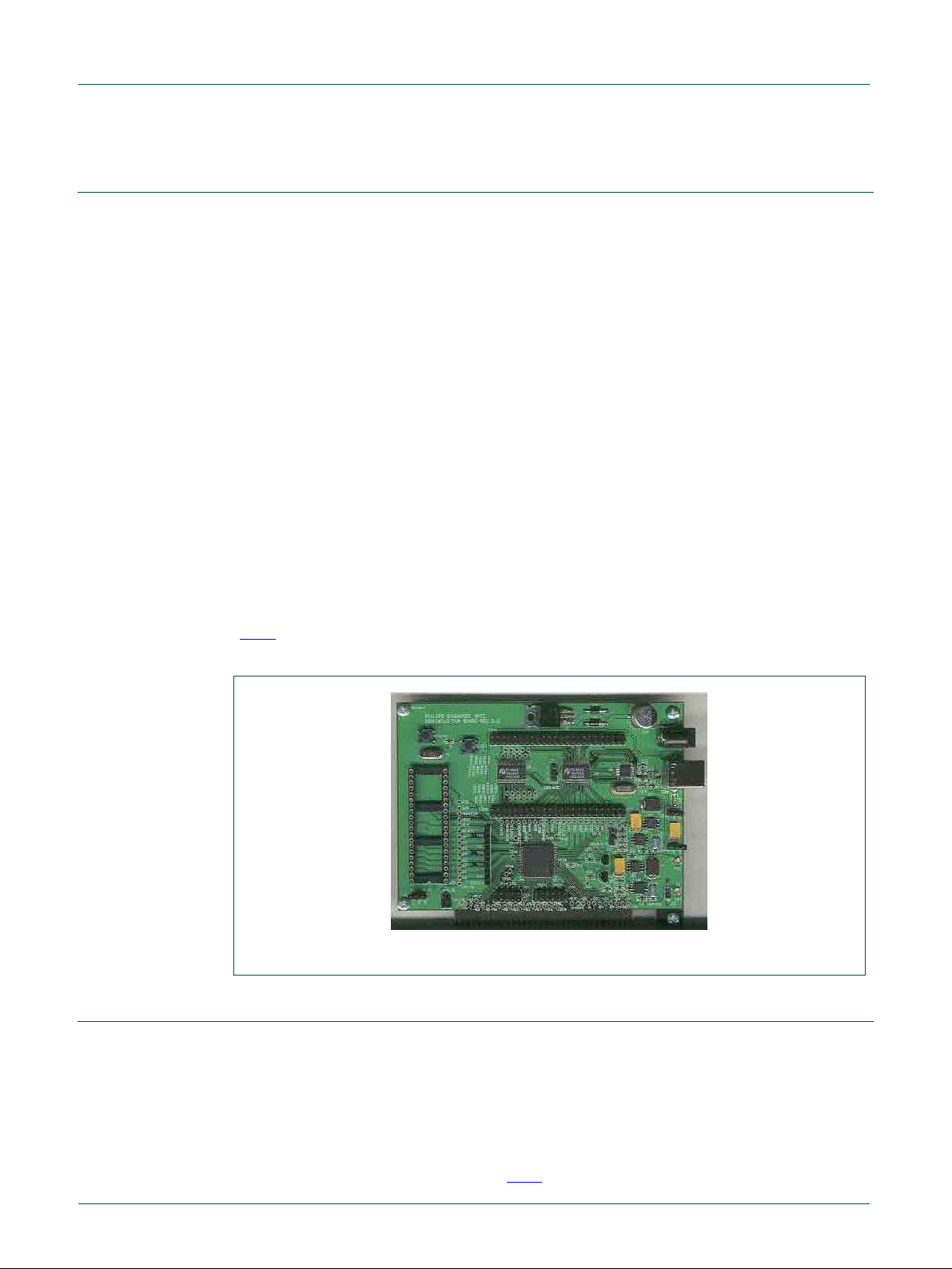
The ISP1183 PC evaluation (eval) kit uses two PCs as a complete USB development
environment, a host PC with USB host capability and a peripheral PC running the
ISP1183 firmware. The ISP1183 eval board is plugged in the peripheral PC as a USB
peripheral.
With this set up, you can easily evaluate the features of the ISP1183, and develop
firmware and product prototype, without being limited by the choice of a microcontroller.
The firmware is written in C, that supports Borland Turbo C for x86.
Fig 1 shows the ISP1183 eval board.
Fig 1. ISP1183 eval board
2. System requirements
For the host PC:
• PC with USB motherboard or add-on card.
• Microsoft Windows 98 and Windows 200 0.
For the peripheral PC:
• PC with Microsoft DOS 6.x.
• ISP1183 eval board, as shown in
UM10044_4 © NXP B.V. 2007. All rights reserved.
User manual Rev. 04 — 6 February 2007 3 of 18
Fig 2.
Page 4
NXP Semiconductors
ISP1183 Low-Power USB Peripheral Controller PC Eval Kit
For the firmware development:
• x86 CPU platform: Borland Turbo C++ 3.0 or above.
• ISP1183 eval diskette.
UM10044
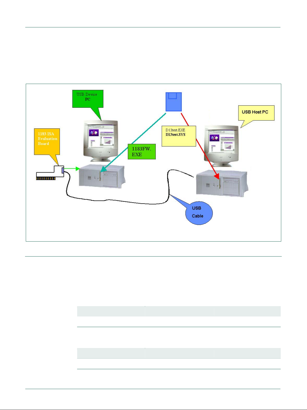
Fig 2. System structure of the ISP1183 PC eval kit
3. Jumper settings on the ISP1183 eval board
The ISP1183 eval board is plugged into the peripheral PC. It will occupy I/O and IRQ
resources of the peripheral PC. To avoid possible conflicts in settings, remove all
unnecessary cards from the peripheral PC. Sound cards and network cards may cause
IRQ conflicts.
Jumper JP1 enables and disables the level-shift module.
Table 1. JP1
Isolate data bus Disable Enable (default)
Short pins 1 - 2 2 - 3
JP2 sets the I/O power supply of the eval board. Default setting is 1.8 V.
Table 2. JP2
I/O voltage select 1.8 V (default) 3.3 V
Short pins 1 - 2 2 - 3
UM10044_4 © NXP B.V. 2007. All rights reserved.
User manual Rev. 04 — 6 February 2007 4 of 18
Page 5

NXP Semiconductors
UM10044
ISP1183 Low-Power USB Peripheral Controller PC Eval Kit
JP4 sets the IRQ number for the ISP1183 eval board. Default setting is IRQ5 as shown
Table 3. Short Intx_IRQ and pin 5.
in
Table 3. JP4
IRQ number IRQ5 (default) IRQ3 IRQ4 IRQ6 IRQ7
Short pins 5 - Intx_IRQ 3 - Intx_IRQ 4 - Intx_IRQ 6 - Intx_IRQ 7 - Intx_IRQ
Jumper JP5 is reserved (left open).
Table 4. S2
Microcontroller power supply 5 V (default) 3.3 V
Short pins 1 - 2 2 - 3
Table 5. S4
Board power supply Bus-powered Self-powered (default)
Short pins 1 - 2 2 - 3
Table 6. S5
V
BUS
Short pins 1 - 2 2 - 3
Table 7. Possible conflict settings
IRQ number Possible conflict
IRQ5 Creative SoundBlaster and compatible sound cards always occupy this IRQ, by
IRQ7 Used by parallel port, by default. May cause printing problem on peripheral PC.
4. I/O mapping
The ISP1183 eval board occupies eight I/O locations. The base address is 368h.
Table 8. I/O mapping
Offset Usage
0 ISP1183 data register, read or write
1 Write command register, read data bus state
power supply Bus-powered (default) Self-powered
default. If this type of sound card is installed, check its settings or remove it.
Some network cards may also use this IRQ.
2 Board control and read chip I/O state
3 Reserved
4 to 7 Reserved for expansion board
UM10044_4 © NXP B.V. 2007. All rights reserved.
User manual Rev. 04 — 6 February 2007 5 of 18
Page 6
NXP Semiconductors
ISP1183 Low-Power USB Peripheral Controller PC Eval Kit
UM10044
5. Installing hardware, firmware, INF and driver
The procedure to install hardware, firmware, INF and driver is as follows:
1. Switch off the peripheral PC.
2. Remove all unnecessary cards on the peripheral PC.
3. Plug the ISP1183 eval board in the ISA slot of the peripheral PC.
4. Switch on the peripheral PC.
5. On the peripheral PC, under the DOS mode, run firmware 1183FW.EXE.
If it is the first time that the eval board is connected to the host PC, the host OS Device
Manager will prompt for the installation of INF and drivers.
6. Select the location of D13TEST.INF and D13TEST.SYS from the ISP1183 evaluation
diskette and complete the installation procedure.
6. Using the host applet
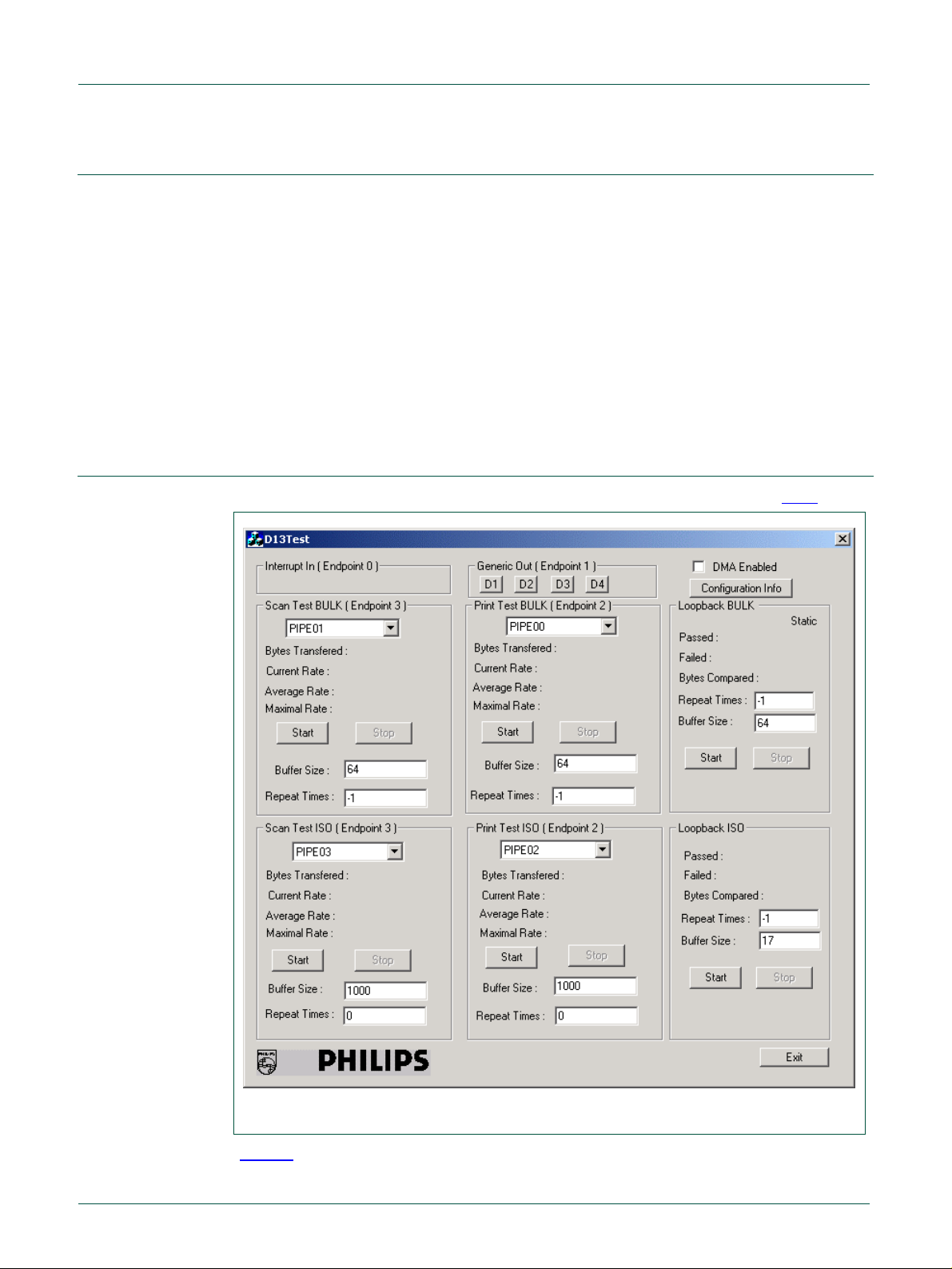
Test applet D13TEST.EXE exercises all the ISP1183 endpoints as shown in Fig 3.
Fig 3. D13Test applet
Table 9 shows a description of endpoints operation on the ISP1183 eval board.
UM10044_4 © NXP B.V. 2007. All rights reserved.
User manual Rev. 04 — 6 February 2007 6 of 18
Page 7

NXP Semiconductors
UM10044
ISP1183 Low-Power USB Peripheral Controller PC Eval Kit
Table 9. Description of endpoints operation
The test applet and the ISP1183 eval board support three test modes: loopback, print
and scan. The firmware uses I/O accesses on this endpoint.
Endpoint number Endpoint type Operations
5 ISO-OUT This pipe is defined as an isochronous OUT pipe.
6 ISO-IN This pipe is defined as an isochronous IN pipe.
3 Bulk-OUT This pipe is defined as a bulk OUT pipe. Supports DMA.
4 Bulk-IN This pipe is defined as a bulk IN pipe. Supports DMA.
Three test modes:
• Scan mode: In this mode, the ISP1183 eval board acts like a scanner. It sends data
packets to the host PC as fast as possible. Use this mode to evaluate the
isochronous IN and bulk IN transfer rates.
• Print mode: In this mode, the ISP1183 eval board acts like a p rinte r. It receives data
packets from the host PC as fast as possible. Use this mode to evaluate the
isochronous OUT and bulk OUT transfer rates.
• Loopback mode: In this mode, the ISP1183 eval board receives data packets on the
isochronous OUT (or bulk OUT) endpoint and sends them back to the host PC o n
isochronous IN (or bulk IN) endpoint. Use this mode to test the data integrity of
transfers.
The Buffer Size setting of the test applet is determined by firmware and hardware ability
of the eval board. For ISA mode, the maximum size is limited to 64000 bytes for the bulk
transfer and 256 bytes for the ISO transfer. For ISO scan mode, if you need to change
the buffer size, print a buffer of the same data size first. By default, Buffer Size is set to
64000 when the test applet is launched. Change Buffer Size to 64 before starting the
test.
Repeat Times for the loopback test controls the numbers of iterations of loopback, which
is useful for debugging. By default, Repeat Times is set to 0 when the test applet is
launched. To run the test infinite times, set Repeat Times to –1.
7. Testing control endpoints using standard USB compliance tool
To test control endpoints using the standard USB compliance tool:
1. Run the USB compliance tool.
The USB Compliance Tool
2. Connect a USB peripheral.
1
window appears, as in Fig 4.
1. In this document, names of windows and dialog boxes are indicated in italic.
UM10044_4 © NXP B.V. 2007. All rights reserved.
User manual Rev. 04 — 6 February 2007 7 of 18
Page 8

NXP Semiconductors
UM10044
ISP1183 Low-Power USB Peripheral Controller PC Eval Kit
Fig 4. USB Compliance Tool window
3. In the USB Compliance Tool window, click the Full Test2 button.
Fig 5. Device Framework Tests dialo g box
2. In this document, items that you click or type are indicated in bold.
UM10044_4 © NXP B.V. 2007. All rights reserved.
User manual Rev. 04 — 6 February 2007 8 of 18
Page 9

NXP Semiconductors
ISP1183 Low-Power USB Peripheral Controller PC Eval Kit
4. In dialog box Device Framework Tests, as seen in Fig 5, deselect Perform Remote
Wakeup and select In A Continuous Loop.
5. Click the Start Automated Testing button.
The Full Test Results dialog box appears, as seen in
6. To stop the loop test, click Stop Testing.
Fig 6.
UM10044
Fig 6. Full Test Results dialog box
The USBCV testing tool can be downloaded from the USB website. Check the website
for the latest version of the tool.
UM10044_4 © NXP B.V. 2007. All rights reserved.
User manual Rev. 04 — 6 February 2007 9 of 18
Page 10

NXP Semiconductors
UM10044
ISP1183 Low-Power USB Peripheral Controller PC Eval Kit
8. Schematics
CON6
VDD
DGND
DGND
8~15V DC IN
DC1
220 μF/10 V
R29
100 Ω
1
2
3
V
CC(3V3)
R7
1 kΩ
C5
0.1 μ
F
D6
IN5401
U6
1
OUT
2
FB3/5 EXT
3
SHDN
REF4V+
MAX1626
C35
220 μF/50 V
L1
CDRH125-220
GND
CS
1
Vin
8
7
6
5
V
U9
+5 V
LM7805
GND
3
Q2
MMSF3PO2HD
RSENSE1
, 1%
0.04 Ω
CC
C6
0.47 μF
DC5
100 μF/10 V
,
1/2W
2
Power supply module
D7
IN5401
C36
C34
0.1 μF
100 μF
D1
MBRS340T3
self-power
R9
26 kΩ,1%
ISA-5V
DC2
C7
R8
VBUS
100 μF/10 V
D3
IN5401
L3
BLM21P221SG
V
CC(3V3)
V
(1V8)
220 pF
10 kΩ,1%
R28
100 Ω
0.1 μF
C8
self-power
bus-power
JP2
U7
1
OUT
2
FB3/5 EXT
3
SHDN
REF4V+
MAX1627
S4
S5
C13
0.1 μF
CDRH125-220
GND
CS
DC3
100 μF/10 V
DC4
22 μF/10 V
V
(1V8)
L2
8
7
MMSF3PO2HD
6
RSENSE2
5
0.04 Ω, 1% 1/2W
V
CC
C9
DC6
V
CC
VBUS_N
Q3
0.47 μF
D2
MBRS340T3
47 μF/10 V
Fig 7. Power supply module
R18
4.7 kΩ
48
OE
RDX
WRX
CSX
RSTX
WAKEUP
A0
TEST30
DACK DACK'
UD7
UD6
UD5
UD4
UD3
UD2
UD1
UD0
OE
1OE
47
1A1
46
1A2
45
GND
44
1A3
43
1A4
42
41
40
39
38
37
36
35
34
33
32
31
30
29
28
27
26
25
VCCA
1A5
1A6
GND
1A7
1A8
2A1
2A2
GND
2A3
2A4
VCCA
2A5
2A6
GND
2A7
2A8
2OE
VCCB
VCCB
P174AVC164245
1
V
CC(3V3)
JP1
C19
0.1 μF
C20
0.1 μF
2
(1V8)
V
DIR
1B1
1B2
GND
1B3
1B4
1B5
1B6
GND
1B7
1B8
2B1
2B2
GND
2B3
2B4
2B5
2B6
GND
2B7
2B8
2DIR
U4
1
2
BRD
BWR
3
4
5
BCS
6
BRST
7
8
BWAKEUP
9
BA0
10
11
TEST31
12
DB7
13
14
DB6
15
16
DB5
DB4
17
18
19
DB3
20
DB2
21
DB1
22
23
DB0
RDWR
24
V
CC(3V3)
Level shift module
C21
0.1 μF
C22
0.1 μF
C23
0.1 μF
OE
(1V8)
INTX
V
VBUSONX
SUSPEND
OE
48
1OE
47
1A1
46
1A2
45
GND
44
1A3
43
1A4
42
VCCA
41
1A5
40
1A6
39
GND
38
1A7
37
1A8
36
2A1
35
2A2
34
GND
33
2A3
32
2A4
31
VCCA
30
2A5
29
2A6
28
GND
27
2A7
26
2A8
25
2OE
P174AVC164245
DIR
1B1
1B2
GND
1B3
1B4
VCCB
1B5
1B6
GND
1B7
1B8
2B1
2B2
GND
2B3
2B4
VCCB
2B5
2B6
GND
2B7
2B8
2DIR
U5
1
BINTX
2
BVBUSON
3
4
5
DREQ'DREQ
BSUSPEND
6
7
8
9
10
11
12
13
14
15
16
17
18
19
20
21
22
23
24
V
CC(3V3)
C24
0.1 μF
Fig 8. Level shifter module
UM10044_4 © NXP B.V. 2007. All rights reserved.
User manual Rev. 04 — 6 February 2007 10 of 18
Page 11

NXP Semiconductors
UM10044
ISP1183 Low-Power USB Peripheral Controller PC Eval Kit
C10
X2
18 pF
Y2
6 MHz
C11
18 pF
X1
CON1
VBUS
GND
CHASSIS
USB_UPCON
VBUS_IN
WAKEUP
SUSPEND
R33
0 Ω
R34
2
No load
1M(no load)
1
VBUS
2
USBD−
D−
3
USBD+
D+
4
USBGND
5
C15
1
3
VREG
5
D−−
7
D++
DREQ
DACK
INTX
MALE CONN 24 X 2
9
11
13
15
17
19
21
23
25
27
29
31
33
35
37
39
41
43
45
47
CON5
10
12
14
16
18
20
22
24
26
28
30
32
34
36
38
40
42
44
46
48
3
Y4
3
2
1
1
0.027 μF, 2 kV
2
4
6
8
VBUS_IN
R11
ISP1183 USB module
VBUS_OUT
33 Ω
A3
A3
B4
B4
C3
C3
D4
D4
E3
E3
EMIF02-USB02
C14
22 pF
RSTX
CSX
TEST30
WRX
RDX
A0
UD0
VBUSONX
GND
UD1
UD2
UD3
UD4
UD5
UD6
UD7
GND
U8
A1
B2
C1
D2
E1
C16
22 pF
MALE CONN 24 X 2
A1
B2
C1
D2
E1
R14
R15
1 2
3 4
5 6
7 8
9 10
11 12
13 14
15 16
17 18
19 20
21 22
23 24
25 26
27 28
29 30
31 32
33 34
35 36
37 38
39 40
41 42
43 44
45 46
47 48
CON4
C33
0.1 μF
22 Ω
22 Ω
RSTX
DACK
DREQ
VBUSONX
VREG
D+
D−
0.1 μF
16
RESET_N
15
DACK
14
DREQ
13
VBUSDET_N
12
V
11
AGND
10
DP
9
DM
C12
C17
0.1 μF
A0
17
A0
REG(3V3)
VBUS
8
VBUS_OUT
UD0
V1V8
19
18
DD(1V8)
V
XTAL27XTAL1
6
X2
X1
C37
0.1 μF
UD1
20
DATA1
DATA0
ISP1183
DGND
5
VDD1
21
DD
V
RD_N
4
RDX
22
DGND
V
WAKEUP
SUSPEND
WR_N
3
WRX
UD3
UD2
24
DATA223DATA3
DGND
DATA4
DATA5
DATA6
DATA7
DD(1V8)
CS_N
1
2
INTX
CSX
U1
INT_N
25
26
27
28
29
30
31
32
UD4
UD5
UD6
UD7
V1V8
WAKEUP
SUSPEND
C18
0.1 μF
Fig 9. ISP1183 USB module
UM10044_4 © NXP B.V. 2007. All rights reserved.
User manual Rev. 04 — 6 February 2007 11 of 18
Page 12

NXP Semiconductors
UM10044
ISP1183 Low-Power USB Peripheral Controller PC Eval Kit
CPLD module
C29
0.1 μF
26
38
CC(I/O)
CC(I/O)
V
V
0.1 μF
51
88
CC(I/O)
V
84
69
C30
TDO
CC(I/O)
V
GND
NC
NC
NC
NC
NC
IO
IO
IO
IO
IO
IO
IO
IO
IO
IO
IO
IO
IO
IO
IO
IO
IO
IO
IO
IO
IO
IO
IO
IO
IO
IO
IO
IO
IO
IO
IO
IO
IO
IO
IO
IO
C31
0.1 μF
C32
0.1 μF
83
41
ISA-ALE
32
D2
49
ISA-A4
50
ISA-A5
35
D0
53
ISA-A7
54
ISA-A8
37
ISA-A0
42
ISA-A3
60
ISA-A11
61
ISA-A12
52
ISA-A6
63
ISA-A13
55
ISA-A9
56
INTX_IRQ
65
DREQ''
58
ISA-A10
59
ISA-CLK
66
ISA-A15
64
ISA-A14
71
ISA-IOW#
72
ISA-AEN
67
ISA-A16
76
ISA-D1
77
ISA-D2
68
ISA-IOR#
70
DACK''
81
ISA-D5
74
ISA-D0
82
ISA-D6
85
ISA-D7
ISA-D3
78
LED1
89
CPLD-CLK
86
90
RDWR
79
ISA-D4
80
ISA-RESET
34
43
46
73
ISA-IORDY#
TDO
C25
0.1 μF
V
CC(3V3)
TCK
TDO
TDI
TMS
R20
1 kΩ
Y3
1
EN
2
NC
GND3O/P
24 MHZ
CPLD-CLK
R21
R22
1 kΩ
1 kΩ
V
CC(3V3)
6
V
CC
5
OE
4
R19
0 Ω
R23
CON3
1 kΩ
FEMALE CON 1X10
1
2
3
4
5
6
7
8
9
10
V
CC(3V3)
TCK
TDI
TMS
ALE
RESET
D6
DREQ'
BVBUSON
BINTX
RD#
WR#
MWAKEUP
MRST
D7
D5
D4
D3
D1
ISA-EN
ISA-A1
ISA-A2
DB7
TEST31
BA0
DACK'
BWAKEUP
BRST
BCS
BWR
BRD
BSUSPEND
LED2
DB0
DB1
DB2
DB3
DB4
DB5
DB6
C26
0.1 μF
48
45
47
22
23
27
13
14
15
16
17
18
20
25
28
29
30
33
36
39
40
99
3
4
1
6
8
9
10
11
12
87
91
92
93
94
95
96
97
2
7
19
24
C27
0.1 μF
U2
TCK
TDI
TMS
IO/GCK1
IO/GCK2
IO/GCK3
IO
IO
IO
IO
IO
IO
IO
IO
IO
IO
IO
IO
IO
IO
7TQ 100C(100)
IO
IO/GSR
IO/GTS1
IO/GTS2
IO
IO
IO
IO
IO
IO
IO
IO
IO
IO
IO
IO
IO
IO
IO
NC
NC
NC
NC
100
C28
0.1 μF
98
VCCINT5VCCINT57VCCINT
XC95144XL-
GND
GND21GND31GND44GND62GND75GND
Fig 10. CPLD module
UM10044_4 © NXP B.V. 2007. All rights reserved.
User manual Rev. 04 — 6 February 2007 12 of 18
Page 13

NXP Semiconductors
UM10044
ISP1183 Low-Power USB Peripheral Controller PC Eval Kit
ISA interface module
ISA-D7
ISA-D6
ISA-D5
ISA-D4
ISA-D3
ISA-D2
ISA-D1
ISA-D0
ISA-IORDY#
ISA-AEN
ISA-A16
ISA-A15
ISA-A14
ISA-A13
ISA-A12
ISA-A11
ISA-A10
ISA-A9
ISA-A8
ISA-A7
ISA-A6
ISA-A5
ISA-A4
ISA-A3
A1
A2
A3
A4
A5
A6
A7
A8
A9
A10
A11
A12
A13
A14
A15
A16
A17
A18
A19
A20
A21
A22
A23
A24
A25
A26
A27
A28
A29
A30
A31
CONN2
IO CK#
D7
D6
D5
D4
D3
D2
D1
D0
IORDY#
AEN
A19
A18
A17
A16
A15
A14
A13
A12
A11
A10
A9
A8
A7
A6
A5
A4
A3
A2
A1
A0
AT62
GND
RESET
+5V
IRQ9
-5V
DRQ2
-12V
OWS
+12V
GND
MEMW#
MEMR#
IOW#
IOR#
DACK3#
DRQ3
DACK1#
DRQ1
REFRESH#
CLK
IRQ7
IRQ6
IRQ5
IRQ4
IRQ3
DACK2#
TC
BALE
+5V
OSC
GND
B1
B2
B3
B4
B5
B6
B7
B8
B9
B10
B11
B12
B13
B14
B15
B16
B17
B18
B19
B20
B21
B22
B23
B24
B25
B26
B27
B28
B29
B30
B31
ISA-5V
ISA-RESET
IRQ 9
DRQ2
ZERO-WAIT
ISA-12V
MEMW#
MEMR#
ISA-IOW#
ISA-IOR#
DACK3#
DRQ3
DACK1
DRQ1
ISA-CLK
IRQ7
IRQ6
IRQ5
IRQ4
IRQ3
DACK#2
D13-EOT
ISA-ALE
INTX_IRQ
DACK''
DREQ''
JP4
1 2
3 4
5 6
7 8
9 10
JP5
1 2
3 4
5 6
7 8
9 10
11 12
HEADER 5X2
HEADER 6X2
IRQ7
IRQ6
IRQ5
IRQ4
IRQ3
DACK1#
DACK2#
DACK3#
DRQ1
DRQ2
DRQ3
Fig 11. ISA interface module
Fig 12. Indicator module
R27
330 Ω
Indicator module
CC
V
D4
LED2
3904
Q5
R24
4.7 kΩ
CC
V
D5
LED1
R26
330 Ω
LED1
LED2
R25
4.7 kΩ
Q4
3904
UM10044_4 © NXP B.V. 2007. All rights reserved.
User manual Rev. 04 — 6 February 2007 13 of 18
Page 14

NXP Semiconductors
UM10044
ISP1183 Low-Power USB Peripheral Controller PC Eval Kit
Microprocessor module
R31
100 kΩ
SW-PB
RESET
ISA-5V
R5
10 kΩ
Q
1
3904
S1
R2
8.2 kΩ
V
CC(3V3)
C1
R4
10 kΩ
R1
1 kΩ
10 μF/16 V
RESET
MCU-X1
VCCM
BINTX
D0
D1
D2
D3
D4
D5
D6
D7
BVBUSON
BSUSPEND
ISA-EN
VCCM
C2
20 pF
Y1
6 MHz
ALE/PROG
9
19
31
10
12
13
14
15
39
38
37
36
35
34
33
32
1
2
3
20
R3
0 Ω
U3
RST
XTAL1
EA/VPP
RXD/P3.0
INT0/P3.2
INT1/P3.3
T0/P3.4
T1/P3.5
P0.0/AD0
P0.1/AD1
P0.2/AD2
P0.3/AD3
P0.4/AD4
P0.5/AD5
P0.6/AD6
P0.7/AD7
P1.0
P1.1
P1.2
VSS
DIP40
MCU-X1 MCU-X2
C3
VCC
PSEN
XTAL2
RD/P3.7
WR/P3.6
TXD/P3.1
P2.7/A15
P2.6/A14
P2.5/A13
P2.4/A12
P2.3/A11
P2.2/A10
P2.1/A9
P2.0/A8
P1.7
P1.6
P1.5
P1.4
P1.3
20 pF
40
29
18
17
16
11
30
28
27
26
25
24
23
22
21
8
7
6
5
4
CC
V
VCCM
MCU-X2
RD#
WR#
ALE
MRST
MWAKEUP
S6
CC(3V3)
V
S2
SW-PB
C4
0.1 μF
R32
10 kΩ
VCCM
Fig 13. Microprocessor
9. Bill of materials
Table 10. Bill of materials
Used Part Type Designator Footprint Description
1 10 µF/16 V C1 CASE_C Capacitor polar
2 18 pF C10 C11 0805 Capacitor
24 0.1 µF C12 C13 C17 C18 C19 C20 C21 C22
C23 C24 C25 C26 C27 C28 C29 C30
C31 C32 C33 C34 C37 C4 C5 C8
2 22 pF C14 C16 0805 Capacitor
1 0.027 µF, 2 kV C15 1206 Capacitor polar
2 20 pF C2 C3 0805 Capacitor
1 220 µF/50 V C35 - Electrolytic capacitor
1 100 µF C36 - Electrolytic capacitor
2 0.47 µF C6 C9 0805 Capacitor
0805 Capacitor
1 220 pF C7 0805 Capacitor
1 USB_UPCON CON1 USB_UPCON USB upstream
connector
UM10044_4 © NXP B.V. 2007. All rights reserved.
User manual Rev. 04 — 6 February 2007 14 of 18
Page 15

NXP Semiconductors
UM10044
ISP1183 Low-Power USB Peripheral Controller PC Eval Kit
Used Part Type Designator Footprint Description
1 FEMALE CON1 X 10 CON3 - Connector
2 MALE CONN 24 X 2 CON4 CON5 - Connector
1 8~15V DC IN CON6 - DC-JACK
1 AT62 CONN2 - Gold finger
2 MBRS340T3 D1 D2 - Schottky diode
3 IN5401 D3 D6 D7 - Diode
1 LED2 D4 LED LED
1 LED1 D5 LED LED
1 220 µF/10 V DC1 - Electrolytic capacitor
3 100 µF/10 V DC2 DC3 DC5 - Electrolytic capacitor
1 22 µF/10 V DC4 - Electrolytic capacitor
1 47 µF/10 V DC6 - Electrolytic capacitor
5 - JP1 JP2 S2 S4 S5 - Jumper
1 HEADER 5X2 JP4 - Connector
1 HEADER 6X2 JP5 - Connector
2 CDRH125-220 L1 L2 - Inductor
1 BLM21P221SG L3 1206 Inductor
3 3904 Q1 Q4 Q5 - NPN transistor
2 MMSF3PO2HD Q2 Q3 - 6 1 kΩ R1 R20 R21 R22 R23 R7 0805 Resistor
1 33 Ω R11 0805 Resistor
2 22 Ω R14 R15 0805 Resistor
3 4.7 kΩ R18 R24 R25 0805 Resistor
2 0 Ω R19 R3 0805 Resistor
1 8.2 kΩ R2 0805 Resistor
2 330 Ω R26 R27 0805 Resistor
3 100 Ω R28 R30 R29 0805 Resistor
1 100 kΩ R31 0805 Resistor
3 10 kΩ R32 R4 R5 0805 Resistor
1 0 Ω R33 - Resistor
UM10044_4 © NXP B.V. 2007. All rights reserved.
User manual Rev. 04 — 6 February 2007 15 of 18
Page 16

NXP Semiconductors
UM10044
ISP1183 Low-Power USB Peripheral Controller PC Eval Kit
Used Part Type Designator Footprint Description
1 1 MΩ (No load) R34 0805 Resistor (no load)
1 10 kΩ, 1 % R8 0805 Resistor
1 26 kΩ, 1 % R9 0805 Resistor
2 0.04,1 %, 1/2W Rsense1 Rsense2 - 2 SW-PB S1 S6 - Push-button
99 - TP1 TP10 TP100 TP101 TP102 TP104
TP11 TP12 TP13 TP14 TP15 TP16 TP17
TP18 TP19 TP2 TP20 TP21 TP22 TP23
TP24 TP25 TP26 TP27 TP28 TP29 TP3
TP30 TP31 TP32 TP33 TP34 TP35 TP36
TP37 TP38 TP39 TP4 TP40 TP41 TP42
TP43 TP47 TP48 TP49 TP5 TP50 TP51
TP52 TP53 TP54 TP55 TP56 TP57 TP58
TP59 TP6 TP60 TP61 TP62 TP63 TP64
TP65 TP66 TP67 TP68 TP69 TP7 TP70
TP71 TP72 TP73 TP74 TP75 TP76 TP77
TP78 TP79 TP8 TP80 TP81 TP82 TP83
TP84 TP85 TP87 TP88 TP89 TP9 TP90
TP91 TP92 TP93 TP94 TP95 TP96 TP97
TP98 TP99
- Test pad
1 ISP1183 U1 - ISP1183
1 XC95144XL U2 SQFP14X14-100 (N) CPLD
1 DIP40 U3 CDIP40 Microcontroller
2 PI74AVC164245 U4 U5 TSSOP48 Level shift
1 MAX1626 U6 SO8 CMOS step-up
switching regulators
1 MAX1627 U7 SO8 CMOS step-up
switching regulators
1 EMIF02-USB02 U8 EMIF02-USB02 1 LM7805 U9 TO-3 2 6 MHz Y1 Y2 - Crystal
1 24 MHz Y3 CSX-750 1 No load Y4 CN -
10. References
• ISP1183 Low-power Universal Serial Bus interface device with DMA data sheet
• Universal Serial Bus Specification Rev. 2.0
UM10044_4 © NXP B.V. 2007. All rights reserved.
User manual Rev. 04 — 6 February 2007 16 of 18
Page 17

NXP Semiconductors
UM10044
ISP1183 Low-Power USB Peripheral Controller PC Eval Kit
11. Legal information
11.1 Definitions
Draft — The document is a draft version only. The content is still under
internal review and subject to formal approval, which may result in
modifications or additions. NXP Semiconductors does not give any
representations or warranties as to the accuracy or completeness of
information included herein and shall have no liability for the consequences
of use of such information.
11.2 Disclaimers
General — Information in this document is believed to be accurate and
reliable. However, NXP Semiconductors does not give any representations
or warranties, expressed or implied, as to the accuracy or completeness of
such information and shall have no liability for the consequences of use of
such information.
Right to make changes — NXP Semiconductors reserves the right to make
changes to information published in this document, including without
limitation specifications and product descriptions, at any time and without
notice. This document supersedes and replaces all information supplied prior
to the publication hereof.
Suitability for use — NXP Semiconductors products are not designed,
authorized or warranted to be suitable for use in medical, military, aircraft,
space or life support equipment, nor in applications where failure or
malfunction of a NXP Semiconductors product can reasonably be expected
to result in personal injury, death or severe property or environmental
damage. NXP Semiconductors accepts no liability for inclusion and/or use of
NXP Semiconductors products in such equipment or applications and
therefore such i nclusion and/or us e is for the customer’s own risk.
Applications — Applications that are described herein for any of these
products are for illustrative purposes only. NXP Semiconductors makes no
representation or warranty that such applications will be suitable for the
specified use without further testing or modification.
11.3 Trademarks
Notice: All referenced brands, product names, service names and
trademarks are property of their respective owners.
UM10044_4 © NXP B.V. 2007. All rights reserved.
User manual Rev. 04 — 6 February 2007 17 of 18
Page 18

NXP Semiconductors
UM10044
ISP1183 Low-Power USB Peripheral Controller PC Eval Kit
12. Contents
1. Introduction .........................................................3
2. System requirements..........................................3
3. Jumper settings on the ISP1183 eval board .....4
4. I/O mapping..........................................................5
5. Installing hardware, firmware, INF and driver...6
6. Using the host applet..........................................6
7. Testing control endpoints using standard USB
compliance tool...................................................7
8. Schematics ........................................................10
9. Bill of materials..................................................14
10. References.........................................................16
11. Legal information ..............................................17
11.1 Definitions............................................................17
11.2 Disclaimers..........................................................17
11.3 Trademarks.........................................................17
12. Contents.............................................................18
Please be aware that important notices concerning this document and the product(s)
described herein, have been included in the section ‘Legal information’.
© NXP B.V. 2007. All rights reserved.
For more information, please visit: http://www.nxp.com.
For sales office addresses, email to: salesaddresses@nxp.com.
Date of release: 6 February 2007
Document identifier: UM10044_4
 Loading...