

Page 1

© 2019 NXP B.V.
i.MX 8QuadXPlus MEK Board Hardware User's
Guide
1. Introduction
This document is the Hardware User’s Guide for the
i.MX 8QuadXPlus Multisensory Enablement Kit (MEK)
based on the NXP Semiconductor’s i.MX 8QuadXPlus
Applications Processor. This board is fully supported by
NXP Semiconductor. The user guide includes system
setup and debugging, and provides detailed information
on the overall design and usage of the MEK board from a
hardware system perspective.
1.1. Board Overview
The MEK board is a platform designed to showcase the
most commonly used features of the i.MX 8QuadXPlus
Applications Processor in a small, low cost package. The
i.MX 8QuadXPlus MEK board is a development board,
which gives the user the option of becoming familiar
with the processor before starting development.
Table 1 lists the features of the i.MX 8QuadXPlus MEK
board.
NXP Semiconductors
Document Number:IMX8QXPMEKHUG
User's Guide
Rev. 1
,
01/2019
Contents
1. Introduction ........................................................................ 1
1.1. Board Overview ...................................................... 1
1.2. MEK Kit contents .................................................... 2
1.3. Board revision history ............................................. 3
2. Specifications ..................................................................... 4
2.1. Processor ................................................................. 5
2.2. Boot mode operations and selections ...................... 6
2.3. Power tree................................................................ 6
2.4. LPDDR4 DRAM memory ....................................... 9
2.5. SD card slot (J12) .................................................... 9
2.6. eMMC memory (U23) ............................................. 9
2.7. Ethernet connector (J7) ........................................... 9
2.8. USB Type-C connector (J10) .................................. 9
2.9. Audio input/output (J8) ......................................... 10
2.10. UART connector (J11) .......................................... 10
2.11. JTAG connector (J4) ............................................. 10
2.12. M.2 Connector (J5) ............................................... 11
2.13. MIPI- CSI and MIPI-DSI/LVDS connectors
(J1,J2,J3) ............................................................................. 11
2.14. Board to Board connector (J13)............................. 12
2.15. User interface buttons ............................................ 12
2.16. User Interface LEDs .............................................. 13
2.17. Sensors .................................................................. 13
2.17.1 Accelerometer + Magnetometer (U14) .................. 13
2.17.2 Pressure Sensor with Altimetry (U18) ................... 13
2.17.3 Ambient Light Sensor (U17) ................................. 14
2.17.4 Gyroscope (U10) .................................................... 14
2.18. PCB information ................................................... 15
2.19. MEK design files ................................................... 15
3. MEK Accessories ............................................................. 15
4. Revision History ............................................................... 17
Page 2
Introduction
i.MX 8QuadXPlus MEK Board Hardware User's Guide, Rev. 1, 01/2019
2 NXP Semiconductors
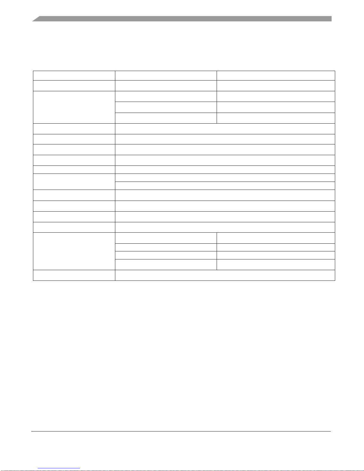
Table 1. Board features
Processor
NXP Applications Processor
PIMX8QX6AVLFZAB *
DRAM memory
Micron 3 GB LPDDR4
MT53B768M32D4DT-062 AIT:B
Mass storage
Micron 32 GB eMMC5.0
MTFC32GAKAEEF-AIT
Micron 512 Mb QSPI NOR
MT35XU512ABA1G12-0AATES
SD card connector
Power
NXP PMIC PF8100 + Discrete DCDC/LDO
Display interface
LVDS / DSI interface interface (Mini-SAS connector)
Ethernet
1 Gbps Ethernet with RJ45 connector
USB
x1 USB (2.0/3.0) Type-C connector
Audio connectors
3.5 mm Audio jack for Headphone + MIC
Debug connectors
JTAG (10-PIN header)
Micro USB for UART debug
Camera
CSI interface (Mini-SAS connector)
Wi-Fi/Bluetooth
x1 M.2 slot (KEY-E type)
Buttons
ON/OFF, RESET
LED Indicators
Power, Reset, PMIC ON and PMIC standby status
Sensors
Accelerometer
FXOS8700CQ
Gyroscope
FXAS21002CQ
Pressure Sensor with Altimetry
MPL3115A2
Ambient light sensor
ISL29023IROZ-T7
PCB
5.24 inch x 5.24 inch (133 mm x 133 mm), 8-layer board
NOTE
The Processor part number may change to latest with respect to future
availability.
1.2. MEK Kit contents
The i.MX 8QuadXPlus MEK contains the following items:
• i.MX 8QuadXPlus CPU Board (MCIMX8QXP – CPU)
• LVDS to HDMI adapter card
• JTAG-GEN2 adapter card
• Power supply (12 V DC,11.5 A, Level VI ,With DIN 4 Pin Output Type )
• AC power cord (IEC cable assembly with locking system for IEC C14 inlet, US version, 1.83 M)
• Worldwide adapter
• Mini SAS cable ( IPASS(Mini-SAS), internal cable, 36 CKT 4X W/ Sidebands )
Page 3

Introduction
i.MX 8QuadXPlus MEK Board Hardware User's Guide, Rev. 1, 01/2019
NXP Semiconductors 3
• Ribbon cable (Ribbon IDC, 1.27 MM, 4", 10POS )
• USB type -C cable ( USB 3.0 Type-A Female, USB Type-C Male, Shielded, 200 mm)
• SD card with BSP image
• Micro USB cable (USB Type-A Male, USB Micro-B Male,1M)
• Quick Start Guide
1.3. Board revision history
• Rev A2
• Rev B1/B2
• Rev C1/C2
The board assembly version will be printed on a label, usually attached to the bottom side. The assembly
version will be the letter designation following the schematic revision: 700-29683 REV _.
Page 4
Specifications
i.MX 8QuadXPlus MEK Board Hardware User's Guide, Rev. 1, 01/2019
4 NXP Semiconductors
2. Specifications
This section provides the detailed information about the electrical design and practical considerations
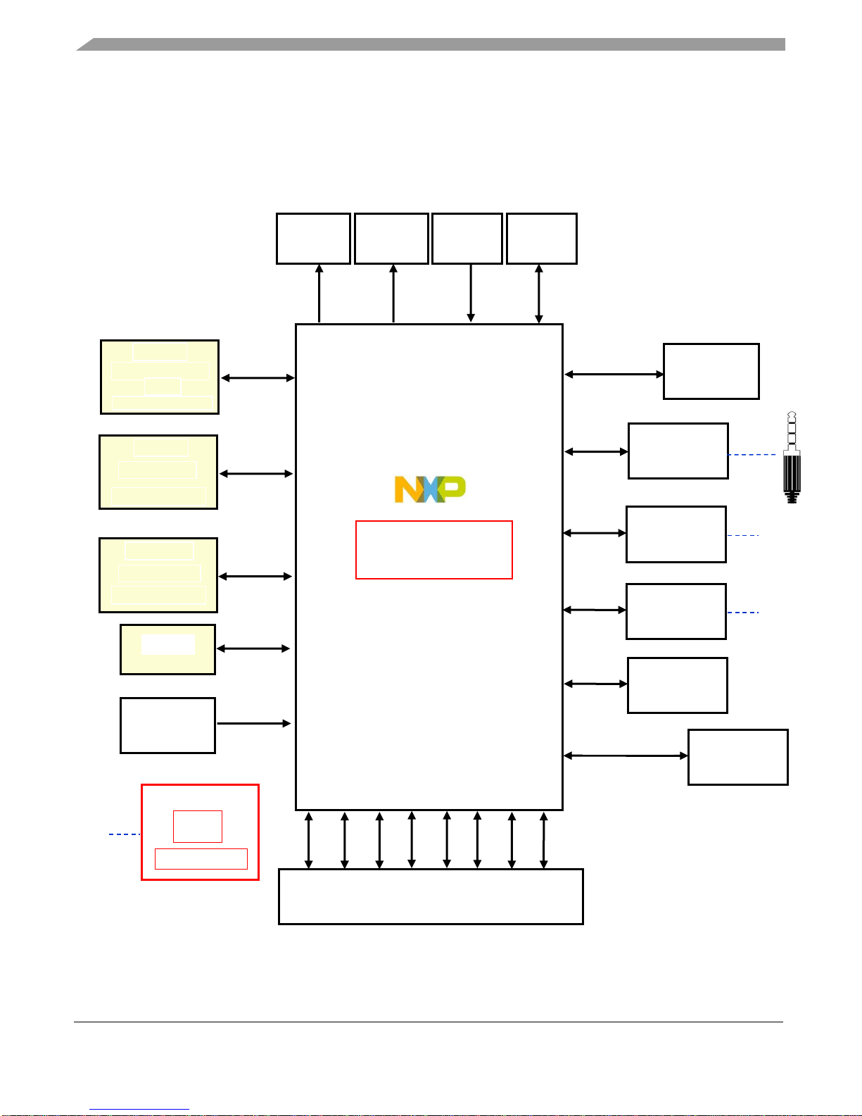
that go into the MEK board. Figure 1 describes each block in the high-level block diagram of the MEK
board.
Figure 1. MCIMX8QXP-MEK block diagram
GROUND
LEFT
RIGHT
MIC
RJ45
Micro
USB
4 PIN
DIN
i.MX 8QuadXPlus
ARM Cortex A35 1.2GHz
4x A35+M4F+HiFi 4 DSP
DSI0/LVDS0
Mini SAS
DSI1/LVDS1
Mini SAS
MIPI CSI
Mini SAS
JTAG
10 Pin
Header
DSI0/
DSI1/
MIPI CSI
JTAG
DRAM
Micron LPDDR4
3GB
MT53B768M32D4DT-062
x32 bits
DRAM
eMMC
Micron 32GB
MTFC32GAKAEEF-AIT
x8 bits
SDIO
SPI Flash
Micron 512MB
MT35XU512ABA1G12
x8 bits
QSPI 0
SDIO
Button
1. ON/OFF
2. Reset
ON/OFF
RESET
M.2
Connector
UART/PCIe/SAI/USB
SD Slot
Audio Codec
SAI
Cirrus Logic
WM8960
RGMII
Ethernet
Qualcomm
AR8031
UART
Debug UART
FTDI Chip
FT2232D
I2C
Sensors
USB
USB Type C
USB 2.0 / USB 3.0
Power Supply
PMIC
PF8100
DC-DC / LDO
Board to Board Connector
for Base Board
CAN
ESAI
CSI
RGMII
SPI
UART
I2C
USB
Page 5
Specifications
i.MX 8QuadXPlus MEK Board Hardware User's Guide, Rev. 1, 01/2019
NXP Semiconductors 5
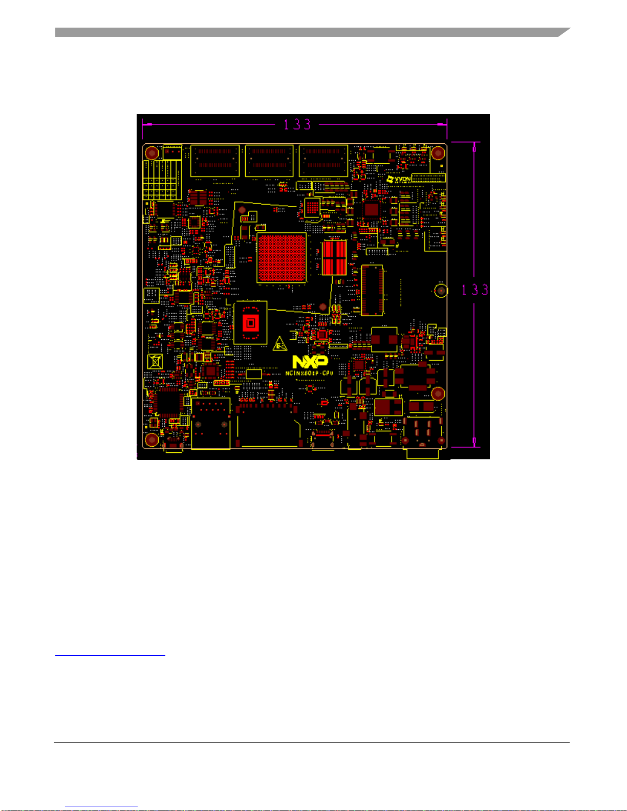
Figure 2 shows the overview of the i.MX 8QuadXPlus MEK board.
Figure 2. i.MX 8QuadXPlus MEK board overview
2.1. Processor
The i.MX 8QuadXPlus processors represent NXP Semiconductor’s latest achievement in integrated
multimedia-focused products offering high performance processing with a high degree of functional
integration, targeted towards the growing market of connected devices. The i.MX 8QuadXPlus
processor features NXP’s advanced implementation of the Quad Arm Cortex®-A35+ Arm Cortex®-M4
core, which operates at speeds up to 1.2 GHz. Each processor provides a 32-bit DDR3L/LPDDR4
memory interface and other interfaces for connecting peripherals, such as WLAN, Bluetooth™, GPS
and camera sensors.
For more detailed information about the processor, please refer to the datasheet and reference manual on
www.nxp.com/imx8X.
Page 6
Specifications
i.MX 8QuadXPlus MEK Board Hardware User's Guide, Rev. 1, 01/2019
6 NXP Semiconductors
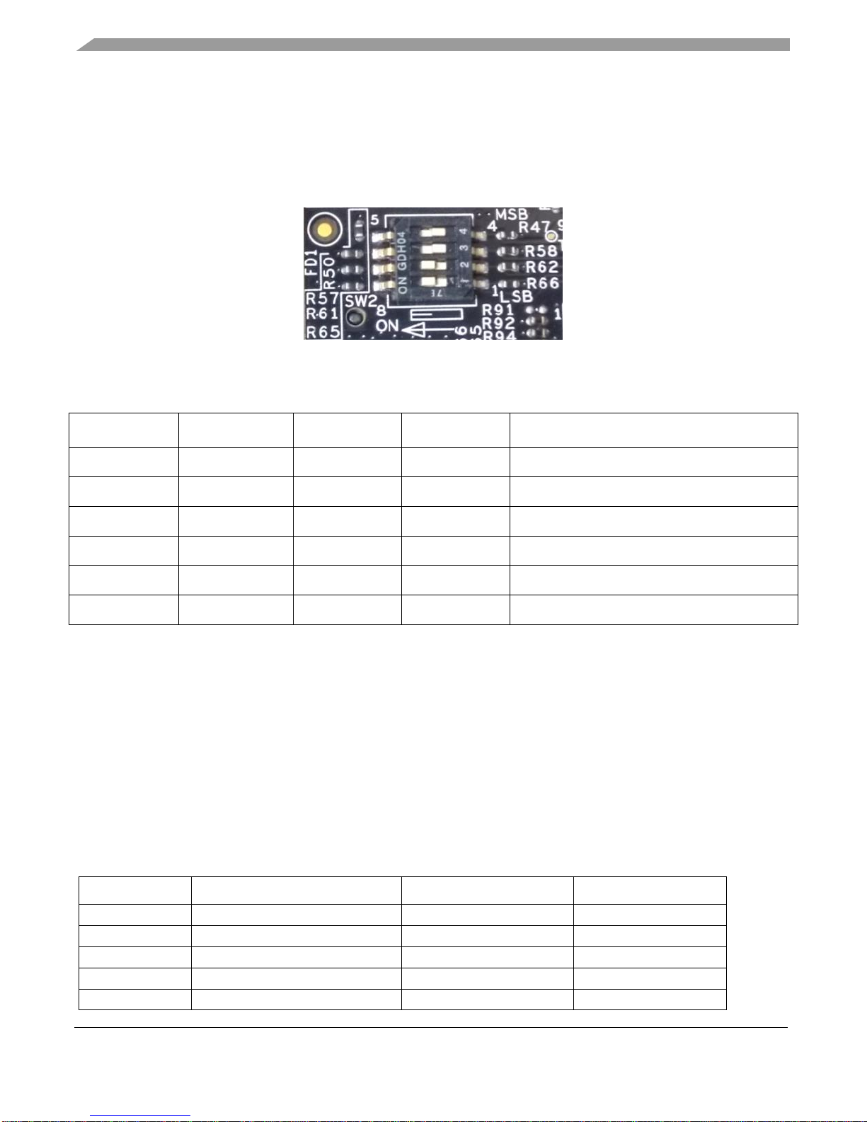
2.2. Boot mode operations and selections
The MEK board based on i.MX 8QuadXPlus Applications Processor is provided with a boot selection
switch (SW2) for determining the boot source device. The user can adjust the various switch positions
and select boot device as shown in Table 2 .
Figure 3. Boot mode selection using SW2
Table 2. Boot selection
BOOT_MODE 3
BOOT_MODE 2
BOOT_MODE 1
BOOT_MODE 0
Boot Device
0 0 0
0
BOOT From Fuse
0 0 0
1
Serial Download
0 0 1
0
EMMC0
0 0 1
1
SD1
0 1 1 0 Serial NOR flash 3B Read
0 1 1
1
Hyperflash 3.3V
On the i.MX 8QuadXPlus MEK board, the default boot mode is from SD card.
2.3. Power tree
There is a +12 V external wall power supply that needs to be connected to the i.MX 8QuadXPlus MEK
board at connector J9. The other powers are generated in the MEK board using PMIC, DC to DC
converters and LDOs. Figure 4 shows the power tree.
Table 3. Power Rails
SEQ
PWR Rail
SRC Type
Value
3
VCC_SNVS
PMIC PF8100
3.0
4
VCC_SCU_1V8
PMIC PF8100
1.8
5
VCC_LDO_SD1
PMIC PF8100
3.3/1.8
4
VCC_MAIN
PMIC PF8100
1.0 8 VCC_GPU
PMIC PF8100
1.1
Page 7

Specifications
i.MX 8QuadXPlus MEK Board Hardware User's Guide, Rev. 1, 01/2019
NXP Semiconductors 7
7
VCC_CPU
PMIC PF8100
1.1
5
VCC_DDRIO
PMIC PF8100
1.1 5 VCC_3V3
PMIC PF8100
3.3 5 VCC_1V8
PMIC PF8100
1.8 2 VCC_EXT_5V0
DC/DC BUCK
5.0 2 VCC_EXT_3V3
DC/DC BUCK
3.3
6
VCC_EXT_1V8
DC/DC BUCK
1.8
1
VCC_12V0
DC Input
12
In Figure 4, the developer can get all the voltage supply rails used on the MEK board. When some
modules are not working, the developer needs to test whether the voltage of this module is correct.
Table 3 lists the power rails on the board.
Page 8

Specifications
i.MX 8QuadXPlus MEK Board Hardware User's Guide, Rev. 1, 01/2019
8 NXP Semiconductors
DC-DC Buck
IR3895
5V/16A
DC-DC Buck
IR3827
3.3V/6A
PMIC : PF8100
PWR
Voltage
Current
(V)
(mA)
3V
VSNVS
BUCK (1 & 2)
BUCK 3
BUCK 4
VDDIO
BUCK 5
BUCK 6
BUCK 7
LDO 1
LDO 2
1V
1.1V
1.1V
1.1V
1.8V
3.3V
1.8V
3.3V
1.8V
2500
2500
2500
2500
2500
5000
10
400
400
i.MX 8QuadXPlus
PWR
Voltage
(V)
3V
VDD_SNVS
VDD_MAIN, VDD_MEMS
VDD_GPU
VDD_CPU
1.8V I/0 (LV GPIO)
3.3V I/0 (HV GPIO)
VDD_DDRIO
VDD_SCU
SD CARD 0
1V
1.1V
1.1V
1.1V
1.8V
3.3V
1.8V
3.3V
DC IN (12V)
CPU FAN
TYPE C
Connector
3x
Mini SAS
LPDDR4
eMMC
NOR
Flash
Audio
Codec
Sensors
RGMII
PHY
Status
LEDs
DC-DC Buck
IR3827
1.8V/6A
Load Switch
Load Switch
EN
EN
VCC_3V3
EN
EN
EN
VCC_1V8
Audio
Connectors
2x CAN
RS 232
ETHERNET
ARDUINO
USB OTG
CSI
M.2
Connector
Load Switch
EN
SD CARD
USDHC1_RESET_B
LDO
2.8V/0.7A
BASE BOARD
Page 9

Specifications
i.MX 8QuadXPlus MEK Board Hardware User's Guide, Rev. 1, 01/2019
NXP Semiconductors 9
Figure 4. Power tree diagram
2.4. LPDDR4 DRAM memory
The i.MX 8QuadXPlus MEK board has one 768 Meg × 32 (4 channels × 16 I/O) LPDDR4 SDRAM
chip (MT53B768M32D4DT-062 AIT:B) for a total of 3 GB RAM memory.
In the physical layout, the LPDDR4 chip is placed on the TOP side, the data traces are not necessarily
connected to the LPDDR4 chips in sequential order, but for ease of routing, are connected as best
determined by the layout and other critical traces.
2.5. SD card slot (J12)
There is one SD card connector (J12) on the i.MX 8QuadXPlus MEK board. This SD card is connected
to USDHC1 of the i.MX 8QuadXPlus application processor. By default, this SD connector supports one
4-bit SD3.0 card.
2.6. eMMC memory (U23)
The eMMC interface is connected to EMMC0 of i.MX 8QuadXPlus. It can support eMMC 5.0. To boot
from eMMC, the Boot-mode switch (SW2) should be changed as shown in Table 2
2.7. Ethernet connector (J7)
There is one gigabit Ethernet module on the i.MX 8QuadXPlus processor. The developer can use the
ENET connector to send/receive the ENET signals. The Ethernet subsystem of the i.MX 8QuadXPlus
MEK board is provided by the Qualcomm AR8031 Ethernet Transceiver (U30). The Ethernet
Transceiver (or PHY) receives standard RGMII Ethernet signals from the i.MX 8QuadXPlus
Applications Processor. The processor takes care of all Ethernet protocols at the MAC layer and above.
The PHY is only responsible for the Link Layer formatting.
The MAC address is set on the MEK board before shipping to the developer and the same is printed on
the SD slot on the Top side of the MEK Board.
2.8. USB Type-C connector (J10)
The i.MX 8QuadXPlus MEK board has a USB Type-C connector on the Top side. The i.MX
8QuadXPlus application processor has a specified USB3/USB2 OTG module to perform USB 3.0 dualrole and USB 2.0 On-The-Go (OTG) compatible with the USB 3.0 specification. The processor has an
additional separate, independent USB 2.0 OTG controller which can be used simultaneously with this
USB 3.0.
The USB_SS3 and the USB_OTG2 are connected to the USB type C connector in the MEK board. The
USB_OTG1 is connected to the USB OTG connector in the base board.
Page 10

Specifications
i.MX 8QuadXPlus MEK Board Hardware User's Guide, Rev. 1, 01/2019
10 NXP Semiconductors
2.9. Audio input/output (J8)
i.MX 8QuadXPlus MEK board includes one Headphone + Mic connector (J8). J8 is a 3.5 mm audio jack
with AHJ pin out. (Rev.D uses AHJ, but previous versions (up to C2) used OMTP pin out).
The Audio codec used on the MEK board is CIRRUS LOGIC Low Power, high quality Stereo codec,
WM8960. The digital interface between i.MX 8QuadXPlus processor and WM8960 includes four
signals: SAI1_TXD, SAI1_RXD, SAI1_TXC, and SAI1_TXFS. The i.MX 8QuadXPlus also provides
the MCLK to WM8960.
2.10. UART connector (J11)
The i.MX 8QuadXPlus MEK Rev.C Board has two independent UART Ports (UART0, M40_UART0)
for debugging. A USB to serial UART converter IC (FT2232D) is used in the MEK board for converting
the USB signals to UART signals. Make sure the FT2232D driver has been installed on your computer
for proper operation. If not, you may download it from FTDICHIP website and install:
https://www.ftdichip.com/Products/ICs/FT2232D.htm
On the MEK board, UART0_TX & UART0_RX are used to output serial debugging information for
A35-core. M40_UART0_TX & M40_UART0_RX are used to output serial debugging information for
M4-core. No RTS or CTS signals are sent from the Processor to the Debug connector as these signals
are ignored by most applications. The required terminal settings to receive debug information during the
boot cycle are as shown in Table 4
Table 4. Terminal setting parameters
Data Rate
115,200 Baud
Data bits
8
Parity
None
Stop bits
1
2.11. JTAG connector (J4)
The i.MX 8QuadXPlus Applications Processor accepts four JATG signals from an attached debugging
device on dedicated pins. The five JTAG signals used by the processor are:
• JTAG_TCK TAP Clock
• JTAG_TMS TAP Machine State
• JTAG_TDI TAP Data In
• JTAG_TDO TAP Data Out
The fifth signal from the attached debugging device (JTAG_SRST_B) is connected to the Reset
generation circuit on the MEK board.
Page 11

Specifications
i.MX 8QuadXPlus MEK Board Hardware User's Guide, Rev. 1, 01/2019
NXP Semiconductors 11
2.12. M.2 Connector (J5)
The i.MX8QuadXPlus Application processor has only one PCIe interface. It is connected to the M.2
connecter with E-Key on the MEK Board. Other interfaces connected to the M.2 connector are UART,
USB, I2C and SAI.
The M.2 connector is mainly provided on the MEK board for interfacing with various Wi-Fi/Bluetooth
adapter cards having M.2 form factor.
2.13. MIPI- CSI and MIPI-DSI/LVDS connectors (J1,J2,J3)
The i.MX 8QuadXPlus processor supports dual MIPI-DSI/LVDS and single MIPI-CSI. The connectors
are designed to support camera and display daughter cards developed by NXP. The connectors are as
shown in Figure 5.
Figure 5. MIPI-CSI and MIPI-DSI/LVDS connectors
MIPI-CSI Connector
MIPI-DSI / LVDS
…..Connector
Page 12

Specifications
i.MX 8QuadXPlus MEK Board Hardware User's Guide, Rev. 1, 01/2019
12 NXP Semiconductors
2.14. Board to Board connector (J13)
The i.MX8QuadXPlus MEK board has a Board to Board connector on the bottom side for connecting
with the Base board (Need to order separately, MPN :MCIMX8-8X-BB). The following interface
signals of i.MX8QuadXPlus applications processor are connected to the board to board connector to use
with the base board.
• CAN
• Audio (ESAI)
• Parallel Camera Interface
• RGMII
• USB OTG
• LCD (Multiplexed with ESAI)
• Tamper (Multiplexed with Camera interface)
• SPI
• I2C
• UART
2.15. User interface buttons
There are two user interface buttons on the MEK board.
2.15.1. ON/OFF Button (SW3)
The chip supports the use of a button input signal to request main SoC power state changes (i.e. ON or
OFF) from the PMU.
In the ON state, if ON/OFF button is held longer than the 5 s, the power-off interrupt is generated. In the
OFF state, if ON/OFF button is held longer than the 0.5 s, the state will transit from OFF to ON.
2.15.2. Reset button (SW1)
In the ON state, holding the RESET button (SW1) will force to reset the power rails except the
VDD_SNVS on the i.MX 8QuadXPlus MEK board. The reset signal from SW1 is connected to the WDI
pin of the PMIC. Once the button is pressed, the PMIC will turn off the powers and generate a POR
signal to the processor and the peripherals. The i.MX 8QuadXPlus applications processor will be
immediately turned off and reinitiate a boot cycle from the OFF state.
Page 13

Specifications
i.MX 8QuadXPlus MEK Board Hardware User's Guide, Rev. 1, 01/2019
NXP Semiconductors 13
2.16. User Interface LEDs
The following LEDs are provided on the MEK board for status indication.
Table 5. Status Indication LEDs
2.17. Sensors
The i.MX 8QuadXPlus MEK board has four sensors: Accelerometer + Magnetometer (FXOS8700CQ),
Pressure Sensor with Altimetry (MPL3115A2), Ambient light sensor (ISL29023IROZ) and Gyroscope
(FXAS21002CQ). These four sensors are connected to i.MX8QuadXPlus I2C port.
2.17.1 Accelerometer + Magnetometer (U14)
The Accelerometer + Magnetometer IC, FXOS8700CQ from NXP Semiconductors, is a small, lowpower, 3-axis, linear accelerometer and 3-axis, magnetometer combined into a single package. The
device features a selectable I2C or point-to-point SPI serial interface with 14-bit accelerometer and
16-bit magnetometer ADC resolution along with smart-embedded functions.
2.17.2 Pressure Sensor with Altimetry (U18)
The Pressure sensor with Altimetry, MPL3115A2 from NXP Semiconductors, is a compact, piezo
resistive, absolute pressure sensor with an I2C digital interface. MPL3115A2 has a wide operating
LED
DESCRIPTION
D40
Processor RESET status
ON : i.MX 8QuadXPlus is in Reset State , OFF : i.MX
8QuadXPlus is in Active State
D14
SCU PMIC ON request
ON : PMIC is ON , OFF : PMIC is OFF
D15
SCU PMIC Standby
ON : PMIC is in Standby mode , OFF : PMIC is in operational
mode
D8
Ethernet Speed Indication, ON : 1Gbps, OFF : 10/100Mbps
D2
12V Supply ON
D3
EXT_1V8 Supply ON
D4
EXT_3V3 Supply ON
D5
EXT_5V0 Supply ON
D44
According to M.2 module behavior
D45
According to M.2 module behavior
Page 14

Specifications
i.MX 8QuadXPlus MEK Board Hardware User's Guide, Rev. 1, 01/2019
14 NXP Semiconductors
range of 20 kPa to 110 kPa, a range that covers all surface elevations on earth. MPL3115A2's
advanced ASIC has multiple user programmable modes such as power saving, interrupt and
autonomous data acquisition modes, including programmed acquisition cycle timing, and poll-only
modes.
2.17.3 Ambient Light Sensor (U17)
The Ambient light sensor, ISL29023 from INTERSIL, is an integrated ambient and infrared light to
digital converter with I2C (SMBus Compatible) Interface. Its advanced self-calibrated photodiode
array emulates human eye response with excellent IR rejection. The on-chip ADC is capable of
rejecting 50Hz and 60Hz flicker caused by artificial light sources. The lux range select feature
allows users to program the lux range for optimized counts/lux.
2.17.4 Gyroscope (U10)
The Gyroscope IC, FXAS21002C from NXP Semiconductors, is a small, low-power, yaw, pitch, and
roll angular rate gyroscope with 16 bit ADC resolution. The full-scale range is adjustable from
±250°/s to ±2000°/s. It features both I2C and SPI interfaces.
Page 15

MEK Accessories
i.MX 8QuadXPlus MEK Board Hardware User's Guide, Rev. 1, 01/2019
NXP Semiconductors 15
2.18. PCB information
The overall dimensions of the i.MX 8QuadXPlus MEK board PCB are shown in Figure 2. The MEK
board is made with standard 8-layer technology. The material used is TU872-SLK Sp, and the PCB
stack-up information is shown in Table 6.
Table 6. Board stack up information
Layer
Description
Coppoer (Oz.)
Dielectric thickness (mil)
1
Signal 1
Dielectric 3.5
2
GND
1
Dielectric 3
3
Signal 1
Dielectric 8
4
Power 2
Dielectric 18
5
Power 2
Dielectric 8
6
Signal 1
Dielectric 3
7
GND
1
Dielectric 3.5
8
Signal 1
2.19. MEK design files
You can download the schematics, layout file, Gerber files, and BOM from www.nxp.com/imx8X.
3. MEK Accessories
For developers’ wishing to expand the MEK board, can purchase the following optional accessory
boards from NXP website.
To implement display or camera functionality through MIPI-DSI/CSI interface, NXP provides 4
accessories that can be directly attached to the mini-SAS connector on MEK board. The IMX-LVDSHDMI board is included the MEK board kit. The developer can purchase other three accessories from
NXP website.
Table 7 shows the link to each accessory, in which you can find the user guide and design files of the
accessory.
Page 16

MEK Accessories
i.MX 8QuadXPlus MEK Board Hardware User's Guide, Rev. 1, 01/2019
16 NXP Semiconductors
Table 7. Links to accessories for the i.MX8QuadXPlus MEK
Accessory
Description
Link
IMX-MIPI-HDMI
Converts MIPI-DSI signal to HDMI
signal
https://www.nxp.com/part/
IMX-MIPI-HDMI
MX8-DSI-OLED1
MIPI-DSI interface OLED display
kit with touch screen
https://www.nxp.com/part/
MX8-DSI-OLED1
MINISASTOCSI
MIPI-CSI interface camera kit based
on OmniVision chipset OV5640
https://www.nxp.com/part/
MINISASTOCSI
IMX-LVDS-HDMI
Converts LVDS signal to HDMI
signal
https://www.nxp.com/part/
IMX-LVDS-HDMI
NOTE
Contact Marketing or Sales for operational boards
Page 17

Revision History
i.MX 8QuadXPlus MEK Board Hardware User's Guide, Rev. 1, 01/2019
NXP Semiconductors 17
4. Revision History
Table 8 summarizes the changes made to this document since the initial release.
Table 8. Revision history
Revision number
Date
Substantive changes
0
11/2018
Initial release.
1
01/2019
Updates in Section 2.10
Page 18

Document Number:IMX8QXPMEKHUG
Rev. 1
01/2019
How to Reach Us:
Home Page:
www.nxp.com/
Web Support:
www.nxp.com/support
Information in this document is provided solely to enable system and software implementers
to use NXP products. There are no express or implied copyright licenses granted hereunder to
design or fabricate any integrated circuits based on the information in this document. NXP
reserves the right to make changes without further notice to any products herein.
NXP makes no warranty, representation, or guarantee regarding the suitability of its products
for any particular purpose, nor does NXP assume any liability arising out of the application or
use of any product or circuit, and specifically disclaims any and all liability, including without
limitation consequential or incidental damages. “Typical” parameters that may be provided in
NXP data sheets and/or specifications can and do vary in different applications, and actual
performance may vary over time. All operating parameters, including “typicals,” must be
validated for each customer application by customer's technical experts. NXP does not convey
any license under its patent rights nor the rights of others. NXP sells products pursuant to
standard terms and conditions of sale, which can be found at the following address:
nxp.com/SalesTermsandConditions.
While NXP has implemented advanced security features, all products may be subject to
unidentified vulnerabilities. Customers are responsible for the design and operation of their
applications and products to reduce the effect of these vulnerabilities on customer’s
applications and products, and NXP accepts no liability for any vulnerability that is discovered.
Customers should implement appropriate design and operating safeguards to minimize the
risks associated with their applications and products.
NXP, the NXP logo, NXP SECURE CONNECTIONS FOR A SMARTER WORLD,
COOLFLUX, EMBRACE, GREENCHIP, HITAG, I2C BUS, ICODE, JCOP, LIFE VIBES,
MIFARE, MIFARE CLASSIC, MIFARE DESFire, MIFARE PLUS, MIFARE FLEX, MANTIS,
MIFARE ULTRALIGHT, MIFARE4MOBILE, MIGLO, NTAG, ROADLINK, SMARTLX,
SMARTMX, STARPLUG, TOPFET, TRENCHMOS, UCODE, Freescale, the Freescale logo,
AltiVec, C 5, CodeTEST, CodeWarrior, ColdFire, ColdFire+, C Ware, the Energy Efficient
Solutions logo, Kinetis, Layerscape, MagniV, mobileGT, PEG, PowerQUICC, Processor
Expert, QorIQ, QorIQ Qonverge, Ready Play, SafeAssure, the SafeAssure logo, StarCore,
Symphony, VortiQa, Vybrid, Airfast, BeeKit, BeeStack, CoreNet, Flexis, MXC, Platform in a
Package, QUICC Engine, SMARTMOS, Tower, TurboLink, and UMEMS are trademarks of
NXP B.V. All other product or service names are the property of their respective owners. Arm,
AMBA, Arm Powered, Artisan, Cortex, Jazelle, Keil, SecurCore, Thumb, TrustZone, and
μVision are registered trademarks of Arm Limited (or its subsidiaries) in the EU and/or
elsewhere. Arm7, Arm9, Arm11, big.LITTLE, CoreLink, CoreSight, DesignStart, Mali, Mbed,
NEON, POP, Sensinode, Socrates, ULINK and Versatile are trademarks of Arm Limited (or its
subsidiaries) in the EU and/or elsewhere. All rights reserved. Oracle and Java are registered
trademarks of Oracle and/or its affiliates. The Power Architecture and Power.org word marks
and the Power and Power.org logos and related marks are trademarks and service marks
licensed by Power.org.
© 2018-2019 NXP B.V.
 Loading...