

Page 1
Quick Start Guide
Evaluation Kit
Based on i.MX 6UltraLite Applications Processor
Page 2
2
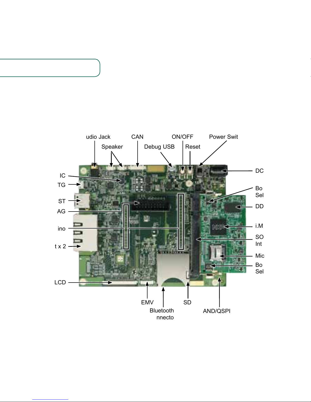
Figure 1: Main interfaces of i.MX 6UltraLite EVK
GET TO KNOW THE EVALUATION KIT BASED ON i.MX 6ULTRALITE
APPLICATIONS PROCESSOR
i.MX 6UltraLite
MIC
USB OTG
USB HOST
JTAG
Arduino
Ethernet x 2
LCD
NAND/QSPI NOR
EMV
Bluetooth®
connector
(bottom side)
SD
Boot Device
Select Switch
MicroSD/eMMC
SODIMM
Interface
Boot Mode
Select Switch
DDR3L
DC IN: 5 V/4 A
Power SwitchCANAudio Jack ON/OFF
Speaker ResetDebug USB
Page 3

3
www.nxp.com
ABOUT THE EVALUATION KIT BASED ON i.MX 6ULTRALITE
The Evaluation Kit (EVK) based on i.MX
6UltraLite introduces developers to the
i.MX 6UltraLite applications processor. To
speed up development, hardware design
files, tools and board support packages
(BSPs) for Linux® are available at
www.nxp.com/iMX6ULEVK.
There are some peripheral boards that
work with the i.MX 6UltraLite EVK to
provide additional capabilities such
as resistive touch display, EMV and
Bluetooth/Wi-Fi® connectivity. Refer to
www.nxp.com/iMX6ULEVK for further
information.
Page 4

44
The following features are available with the EVK based on i.MX 6UltraLite
applications processor:
• i.MX 6UltraLite applications processor
with a 696 MHz ARM® Cortex®-A7 core
• 4 GB DDR3L SDRAM, 400 MHz
• 256 MB QSPI NOR Flash
• eMMC (unpopulated)
• NAND flash (unpopulated)
• MicroSD® connector
• SD connector
• LCD expansion port connector
• USB OTG connector
• USB Host connector
• 3.5 mm audio stereo headphone jack
• Board-mounted microphone
• L/R speaker connectors
• Two 10/100 Mbit/s Ethernet connectors
• CAN bus connector
• Sensors including:
- three-axis accelerometer
- Digital compass
- Gyroscope (unpopulated)
• JTAG 20-pin 2.54 mm connector
• Debug port for ARM Cortex-A7 core
via USB micro-B connector
• Bluetooth connector
FEATURES
Page 5

www.nxp.com
55
GETTING STARTED
This section describes how to use the evaluation kit and the required accessories to
develop applications using the evaluation kit.
1
Unpacking
the Kit
The evaluation kit is shipped with the items listed in Table 1. Ensure the items are
available in the i.MX 6UltraLite Evaluation Kit.
ITEM DESCRIPTION
CPU board
CPU board with i.MX 6UltraLite applications processor, memory,
discrete powers and MicroSD card slot
Base Board Peripherals and connectivity board
Documentation Quick Start Guide
Power Supply Output: 5 V/4 A, Plug: 2.1 mm x 5.5 mm
USB Cable USB cable (micro-B to standard-A)
Micro-SD card Bootable Linux image
Table 1: Contents of the i.MX 6UltraLite Evaluation Kit
Page 6

66
2
Prepare
Accessories
The following items in Table 2 are required to run the i.MX 6UltraLite Evaluation Kit.
ITEM DESCRIPTION
LCD Module
(optional)
LCD8000-43T is the validated module, which has a 4.3 inch resistive
touch screen and supports a resolution of up to 480x3(RGB)x272.
Note: An LCD module is not a standard part of the evaluation kit.
Table 2: Optional Equipment
Page 7

www.nxp.com
77
ITEM DESCRIPTION
Documentation
• Schematics, layout and Gerber files
• Quick Start Guide
Software development tools Linux BSPs
Demo images
Copy of the latest Linux BSP images that are
available to program on to the MicroSD card
Table 3: Download Software and Tools Contents
3
Download Software
and Tools
Download installation software and documentation under
“Jump Start Your Design” at www.nxp.com/iMX6ULEVK.
Table 3 lists the documents available on the website.
Page 8

88
SETTING UP THE SYSTEM
1
Insert MicroSD
Card
Insert the MicroSD card into socket J301
on the CPU board (700-28617).
2
Connect USB
Debug Cable
Connect the micro-B end of the supplied
USB cable into debug port J1901 on the
base board (700-28616). Connect the
other end of the cable to a PC acting
as a host terminal. If needed, the serial
to USB drivers can be found at
www.silabs.com/products/mcu/Pages/
USBtoUARTBridgeVCPDrivers.aspx
Open the terminal window (i.e., Hyper
Terminal or TeraTerm) and apply the
following configuration:
• Baud rate: 115200
• Data bits: 8
• Stop bit: 1
• Parity: None
• Flow control: None
3
Connect LCD Module
(optional)
Connect the FPC cable of LCD Module
(LCD8000-43T) to the LCD connector
J901 on base board (700-28616), which is
bottom contact.
Note: The LCD Module is not included in the kit. It is sold
separately at www.nxp.com/iMX6ULEVK.
4
Connect Ethernet Cable
(Optional)
Connect an Ethernet cable to the right
port of the Ethernet Jack J1501.
5
Connect Power
Supply
Connect the plug of the 5 V power
supply to the DC power jack J2001 on
base board (700-28616) and slide power
switch SW2001 to ON. When power is
connected to the EVK, it will automatically
begin the boot sequence.
Page 9

www.nxp.com
9
Figure 3. SW601 setting for internal boot mode
Figure 2. SW602 setting for internal boot mode
BOOT PROCESS FOR LINUX IMAGE
Boot Process
• Change SW602 to D1:ON,D2:OFF (Refer to Table 4) to enter internal boot mode,
and then switch SW601 to D1:OFF, D2:OFF, D3:ON, D4:OFF (Refer to Table 5) to
boot from the MicroSD card, as shown in Figure 2 and Figure 3. After the board
images are programmed and the boot switches are correctly configured, the system
is ready to run.
• Power on the EVK board.
• During the boot process, there will be operating system status information scrolling
on the terminal window of the PC (if connected). The Linux penguin images will
initially appear in the upper left corner of the LCD screen.
• When the boot process is complete, the Linux operating system (Yocto Project) will be
displayed on the LCD screen.
• To work from the terminal window on the host PC, press ‘Enter’ at the terminal
window to get the command prompt. Account name: root, password none.
Page 10

101010
DIP SWITCH CONFIGURATION
Table 4 shows the switch configuration of boot mode for i.MX 6UltraLite EVK. Internal
boot is chosen as default.
Table 5 shows the switch configuration of boot device for i.MX 6UltraLite EVK. MicroSD
is chosen as default.
D1/MODE1 D2/MODE0 BOOT MODE
OFF OFF Boot From Fuses
OFF ON Serial Downloader
ON OFF Internal Boot
ON ON Reserved
Table 4: i.MX 6UltraLite EVK DIP switch configuration (SW602)
D1 D2 D3 D4 BOOT DEVICE
OFF OFF ON OFF MicroSD
OFF OFF OFF OFF QSPI
OFF ON ON OFF EMMC
ON ON OFF ON NAND
Table 5: i.MX 6UltraLite EVK DIP switch configuration (SW601)
Page 11

www.nxp.com
11
Button Functions
Table 6 shows the functions of the push buttons and switches on the board.
ITEM DESCRIPTION
SW2101
Evaluation kit ON/OFF button
• In Yocto Project, short press and long press will only generate an interrupt,
the usage could be defined by upper software.
• Prolonged depress (>5 sec) will force an immediate hardware shutdown.
• If board is in the SHUTDOWN state, short press of the button will restart
(boot) the system.
• If board is in the STANDBY state, short press of the button will bring the
system out of standby (resume operations, no boot).
SW2102
Evaluation kit RESET button
• Press of the button will reset the system and begin a boot sequence.
SW2001
Evaluation kit switch
• Sliding the switch to the ON position connects the 5 V power supply to the
Evaluation Kit main power system.
• Sliding the switch to the OFF position immediately removes all power from
the board.
Table 6: EVK board button operations
Page 12

www.nxp.com/iMX6ULEVK
NXP and the NXP logo are trademarks of NXP B.V. All other product or service names are the property of
their respective owners. ARM and Cortex are registered trademarks of ARM Limited (or its subsidiaries) in
the EU and/or elsewhere. All rights reserved. © 2012, 2014–2017 NXP B.V.
Doc Number: IMX6ULTRALITEQSG REV 4
Agile Number: 926-29013 REV B
Get Started
Download installation
software and documentation
under “Jump Start Your Design”
at www.nxp.com/iMX6ULEVK.
SUPPORT
Visit the i.MX community at
www.imxcommunity.org.
WARRANTY
Visit www.nxp.com/warranty for
complete warranty information.
 Loading...