

Page 1
Freescale Semiconductor
Quick Start Guide
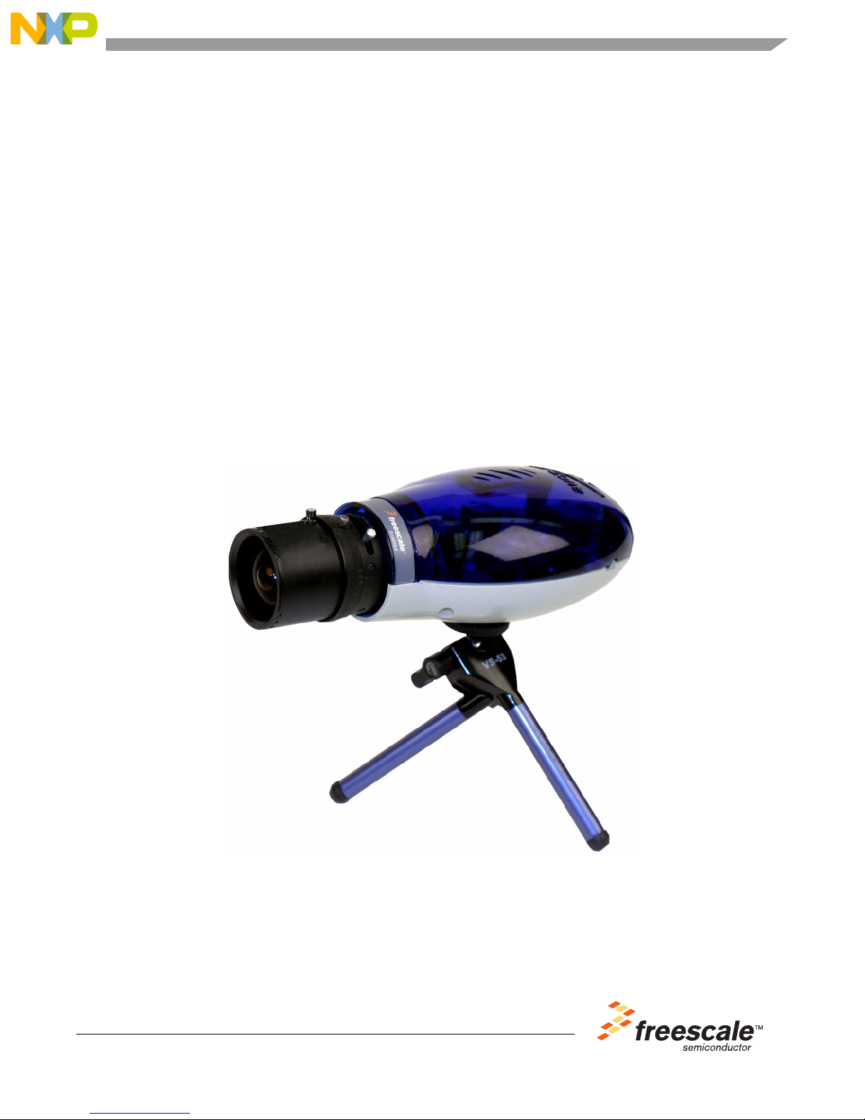
i.MX27 IP Ca me r a Re fe re nc e De si gn
Quick Start Guide
© Freescale Semiconductor, Inc., 2008. All rights reserved.
Page 2

Table of Contents
1. Gettin g Started .... ............................................................................................... ......................... ......... 3
1.1. Camera Kit Contents .... ........ ................ ................ ........ ................. ........ .. ........ ........ ...................... . 3
1.2. CD-ROM Contents ............................................................................................................... ........ . 3
2. Setting up Camera Hardware ............................................................................................................... 4
3. Setting up Camera Software ................................................................................................................ 4
4. Preparing Windows® to View Video Stream .. ....................................... .................... .................... ..... 5
4.1. Internet Explorer 6.0 or 7 .......................................................................................................... ..... 5
4.2. FFPLAY Video C l ient .......... ........ ................ ........ ................. ........ ................ ........ ...................... ... 7
4.3. Starting Video Stream ...... ........ ................ ........ ................. ........ ................ ................ .............. ....... 8
4.4. Changing the Camera IP address using Terminal .......................................................................... 8
5. Revisi o n History ............................................................................. .................................................. 9
2 Freescale Semiconductor
i.MX27 IP Camera Quick Start Guide, Rev . 1
Page 3

Getting Started
1 Getting Started
This document is provided as a quick start guide that will help the user set up the Freescale i.MX27 IP
camera and start a web based session.
1.1 Camera Kit Cont en ts
The IP camera reference design kit is shipped with the items listed in Table 1.
Table 1. IP Camera Reference Design Kit Contents
Type Items
Board • CPU board
• Image Sensor board
CPU board and image sensor board with lens assembled, are housed in a plastic
enclosure.
Cables • RJ45 Ethernet cable
• Modified serial connect or wit h one 9-pin female connection and one 3-pin terminal
block conne ctor.
Power Supply • 12VDC @ 1A power supply with a center positive 2.5mm barrel jack connector.
Other Hardware • Camera Mini Tripod
Paperwork • CD-ROM: Content CD
• End-User License Agreement
• Quick Start Guide (this document)
• Warranty card
• Freescale support card
Verify that all items are contained in the package.
1.2 CD-ROM Contents
The IP camera reference design kit is shipped with the items listed in Table 2.
Table 2. CD-Rom contents
Type Items
Product Documentation • i.MX27 IP Camera Fact Sheet
• Bill o f Ma te rials, Sche m a tic s and Gerber files for CPU board and Image Sensor board.
• i.MX27 IP Camera Software Guide
• i.MX27 IP Camera Reference Manual
• DAP: Au-Zone Fact Sheet
• Data sheets for the IP camera’s non-Freescale components
Freescale Sem iconductor 3
i.MX27 IP Camera Quick Start Guide, Rev . 1
Page 4
Setting up Camera Hardware
2 Setting up Camera Hardware
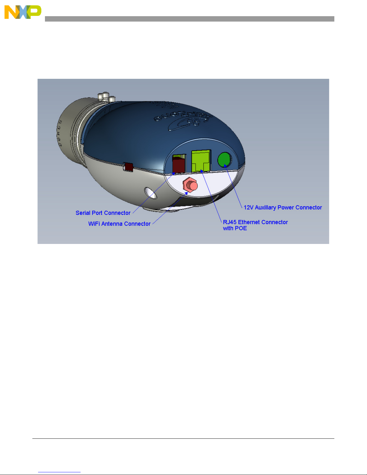
The following section describes the procedure for setting up the camera hardware. Figure 1, below, depicts
various connectors on the back of the unit.
Figure 1. IP Camera Hardware
1. Connect the RJ45 connector to both a local network port and the RJ45 connector located on the
back on the unit. The camera supports Auto-MDI and ther efore does not require a crossover cable.
2. Connect the terminal end of the serial connector on the back of the unit. This is only required i f a
terminal session is required.
3. Connect the female DB9 connector to the serial port on the host P C. Please exercise caution when
connecting and removing the female DB9 connector to ensure that it does not break.
4. The Mini Tripod simply screws into the mount on the bottom of the unit.
5. Apply power by connecting the power adapter to the barrel connector on the back of the board.
This is not required if a POE Ethernet connection is used.
6. Blue LEDs inside the top side of the enclosure indicate that the unit is running when activated.
3 Setting up Camera Software
This section describes the procedure for starting a streaming video session.
Note that the serial connection is not required to run the system. If it is desired that a Linux shell be present,
connect the serial cable to the host PC as described above, and start up a terminal program for an 8-N-1,
115,200 connection. Disable all forms of Flow Control (Flow Control should be set to NONE).
4 Freescale Semiconductor
i.MX27 IP Camera Quick Start Guide, Rev . 1
Page 5

Preparing Windows® to View Video Stream
4 Prep aring Wi ndows® to View Video Stream
This section describes the required procedure for preparing Windows to view the video stream.
In order to stream video in Windows XP™, some basic configuration needs to be completed fir st. The
following applies to Windows XP with Internet Explorer 6.0 or 7.
• Default IP Addresses for the Camera Server – The camera is shipped with the following default IP
addresses.
— Wir ed Network: 192.168.1.254
— The subnet mask is the 255.255.255.0. This means that “192.168.1” is the significant portion
of the IP address and must be the same on the PC in order to communication with the camera.
• To initially connect to the camera and configure it for the broader network, it is recommended to
directly connect the camera to the PC. Then temporarily change t he PC’ s network settings to match
the camera. Connect to the camera and change its settings to the broader network configuration
then change the PC back and reboot the camera. Confirm that the settings are right and connect
both the PC and the camera to the gene ral network.
• All of the above settings can be configured through the web int erface. Note that changes made via
the web interface will be persistent; the camera will retain the new address on reset.
• Wireless connectivity is not supported at this time.
4.1 Inter n et Explorer 6.0 or 7
The following steps explain the required sequence for preparing Internet Explorer 6.0 or 7. Figure 2 and
Figure 3 illustrate them.
1. Open Internet Explorer
2. Ensure proxies are disabled
3. Select Tools menu, then “Internet Options...”, open Security tab.
1. Select “Trusted sites”
2. Press the “Sites…” button.
3. Ensure ‘Require server verification (https: ) ….’ box is not checked
4. Add http://192.168.1.254 or the configured IP for your network.
4. Change the Security Level for this zone to “Low”.
Freescale Sem iconductor 5
i.MX27 IP Camera Quick Start Guide, Rev . 1
Page 6

Preparing Windows® to View Video Stream
Figure 2. Required Sequence to Prepare Internet Explorer 6.0 or 7 (steps 1-4)
6 Freescale Semiconductor
i.MX27 IP Camera Quick Start Guide, Rev . 1
Page 7

Preparing Windows® to View Video Stream
Figure 3. Required Sequ ence to Prepare Internet Explorer 6.0 or 7 (step 5)
When playing video, IE may popup with “Open File—Security Warning”. Unselect “Always ask before
opening this file” and click Run.
Mozilla/Firefox or any othe r web browser will not be able to s how the streaming video.
4.2 FFPLAY Video Client
This section explains how to set up the FFPlay video client.
4.2.1 Installing from the camera web server page
1. Open Internet Explorer and connect to the camera web server at http://192.168.1.254 or the
configured IP address for the camera on your network.
2. From the main page click on the link to download ffplay (“GET FFPLAY”).
3. When installing the program save it to the “C:\Program Files\ffmpeg” directory (if it does not
exist, create the ffmpeg directory).
4. Open Windows Explorer and navigate to “C:\Program Files\ffmpeg”.
5. Right-click on ffmpeg.zip
6. Select “Extract All” and ok the defaults. This will unzip the necessary files
Freescale Sem iconductor 7
i.MX27 IP Camera Quick Start Guide, Rev . 1
Page 8

Preparing Windows® to View Video Stream
4.2.2 Installing using WinZip
1. Open ffmpeg.zip with WinZip
2. Click “Extract”
3. Change the destination directory to “C:\Program Files\ffmpeg”
4. Click “Ok”
The “ffplay.exe” pr ogram must exist in “C:\Program Files\ffmpeg\ffmpeg\bin\” otherwise the video
streaming will not work.
4.3 Starting Video Stream
After web and video server have started on the camera platform, you should be able to connect to the
device using Internet Explorer. Only one connection to the video server at a time is currently allowed.
The default IP address for the wired interface will be 192.168.1.254. You will need to change your
Windows network settings to be able to access it if your subnet is different.
Once you have accessed and changed the network settings on the device to match your network, you will
be able to access the web pages at http://<DEVICE IP ADDRESS>. Once that is loaded, click the “Play
V ideo” link. If you have set upWindows and Internet Explorer as described above, the video will start
playing shortly in a separate window.
4.4 Changing the Camera IP address using Terminal
If the Cameras Subnet mask is not appropriate, it can be changed using a terminal window and the RS-232
cable.
1. Open Hyper-terminal or similar terminal program and connect using 8-N-1, 115200 connection
with no Flow Control.
2. Reset the camera, and the boot messages should appear in the terminal window.
3. Once the unit has completed booting and the mx27# prompt appears, use the following command
to change the IP address of the camera:
ifconfig eth0 <IP address>
4. The IP address will be changed until the next reset. The IP address changes can be made
permanent using the System Settings page of the camera.
8 Freescale Semiconductor
i.MX27 IP Camera Quick Start Guide, Rev . 1
Page 9

5 Revision History
Table 3 provides a revision history for this template.
Table 3. Document Revision History
Revision History
Rev.
Number
0 04/2008 Initial release
1 8/2008 Added Section 1.2, “CD-ROM Contents.” Removed WIFI support f rom Section 3,
Date Substantive Change (s)
“Setti n g u p Ca m e ra So ftware” and Section 4, “Preparing Windows® to View Video
Stream.” Updated Section 4.1, “Internet Explorer 6.0 or 7.”
Freescale Sem iconductor 9
i.MX27 IP Camera Quick Start Guide, Rev . 1
Page 10

Revision Hist ory
THIS PAGE INTENTIONALLY LEFT BLANK
10 Freescale Semiconductor
i.MX27 IP Camera Quick Start Guide, Rev . 1
Page 11

THIS PAGE INTENTIONALLY LEFT BLANK
Revision History
Freescale Sem iconductor 11
i.MX27 IP Camera Quick Start Guide, Rev . 1
Page 12

How to Reach Us:
Home Page:
www.freescale.com
Web Support:
http://www.freescale.com/support
USA/Europe or Locations Not Listed:
Freescale Semiconductor, Inc.
Technical Information Center, EL51 6
2100 East Elliot Road
Tempe, Arizo na 85284
1-800-521-6274 or
+1-480-768-2130
www.freescale.com/support
Europe, Middle East, and Africa:
Freescale Halbleiter Deutschland GmbH
Technical Information Cent er
Schatzbogen 7
81829 Mu en c he n , G erm a ny
+44 1296 380 45 6 (E ng li sh)
+46 8 52 200080 (English )
+49 89 9210 3 55 9 (G er m an )
+33 1 69 35 48 48 (French)
www.freescale.com/support
Japan:
Freescale Semiconductor Japa n Ltd.
Headquarters
ARCO Tower 15F
1-8-1, Shimo-Meguro, Meguro-ku
Tokyo 153-0064
Japan
0120 191014 or
+81 3 5437 91 25
support.japan@freescale.com
Asia/Pacific:
Freescale Semiconductor China Ltd.
Exchange Building 23F
No. 118 Jianguo Road
Chaoyang District
Beijing 100022
China
+86 10 5879 8000
support.asia@freescale.com
For Literatur e Req ues ts Only:
Freescale Semiconductor
Literature Distribution Center
P.O. Box 5405
Denver, Colorado 80217
1-800 441-2447 or
+1-303-675-2140
Fax: +1-303-675-2150
LDCForF reescaleSemiconductor
@hibbertgroup.com
Information in this document is provided solely to enable system and software
implementers to use Freescale Semiconductor products. There are no express or
implied copyright licenses granted hereunder to design or fabricate any integrated
circuits or integrated circuits based on the information in this document.
Freescale Semiconductor reserves the right to make changes without further notice to
any products herein. Freescale Semiconductor makes no warranty, representation or
guarantee regarding the suitability of its products for any particular purpose, nor does
Freescale Semiconductor assume any liability arising out of the application or use of
any product or circuit, and specifically disclaims any and all liability, including without
limitation consequential or incidental damages. “Typical” parameters which may be
provided in Freescale Semiconductor data sheets and/or specifications can and do
vary in different applications and actual performance may vary over time. All operating
parameters, including “Typicals” must be validated for each customer application by
customer’s technical experts. Freescale Semiconductor does not convey any license
under its patent rights nor the rights of others. Freescale Semiconductor products are
not designed, intended, or authorized for use as components in systems intended for
surgical implant into the body, or other applications intended to support or sustain life,
or for any other application in which the failure of the Freescale Semiconductor product
could create a situation where personal injury or death may occur. Should Buyer
purchase or use Freescale Semiconductor products for any such unintended or
unauthorized application, Buyer shall indemnify and hold Freescale Semiconductor
and its officers, employees, subsidiaries, affiliates, and distributors harmless against all
claims, costs, damages, and expenses, and reasonable attorney fees arising out of,
directly or indirectly, any claim of personal injury or death associated with such
unintended or unauthorized use, even if such claim alleges that Freescale
Semiconductor was negligent regarding the design or manufacture of the part.
Freesca l e an d the Free sca l e lo go ar e tr ad ema rks o r reg i ster e d tra de mark s
of Freescale Semiconductor, Inc. in the U.S. and other countries. Microsoft,
and Windows are registered trademarks of Microsoft Corporation; and
Window s XP is a trademark of Microsoft Corporation
. All other p roduct or
servi ce names are the pr operty of their respective owners.
© Freescale Semiconductor, Inc., 2008. All rights reserved.
Document Number: MX27IPCQSG
Rev . 1
08/2008
 Loading...