

Page 1

NXP Semiconductors Document identifier: IEC60730DSCE41UG
User's Guide Rev. 0, 03/2021
IEC60730 DSC Example v4.1
Page 2

NXP Semiconductors
Contents
Chapter 1 Introduction........................................................................................... 3
Chapter 2 Hardware setup.....................................................................................4
Chapter 3 Opening the project...............................................................................6
Chapter 4 Project files structure.............................................................................7
Chapter 5 Project configuration............................................................................. 8
Chapter 6 Loading project into device and debugging.........................................10
Chapter 7 Support................................................................................................12
Chapter 8 Revision history...................................................................................13
IEC60730 DSC Example v4.1, Rev. 0, 03/2021
User's Guide 2 / 14
Page 3

NXP Semiconductors
Chapter 1
Introduction
The IEC60730 v4.1 package for DSCs contains example projects for MC56F81768 (MC56F81000-EVK board) and MC56F83789
(FRDM-MC56F83000 board). These projects are built using the CodeWarrior for MCU IDE v11.1. If your toolchain is not ready
yet, install it according to the instructions in the following chapter.
1.1 Installing the toolchain
Find the web pages for your development board (for example MC56F81000-EVK) and click the getting started user's guide
document in the "Documents" section (see Support). The "Get Software" section contains all the necessary steps to set up
the toolchain.
IEC60730 DSC Example v4.1, Rev. 0, 03/2021
User's Guide 3 / 14
Page 4
NXP Semiconductors
Chapter 2
Hardware setup
With the safety_iec60730b example, the default hardware configuration uses an external PE-Micro Multilink debugger. For other
hardware configuration possibilities, see the web pages for the respective development board.
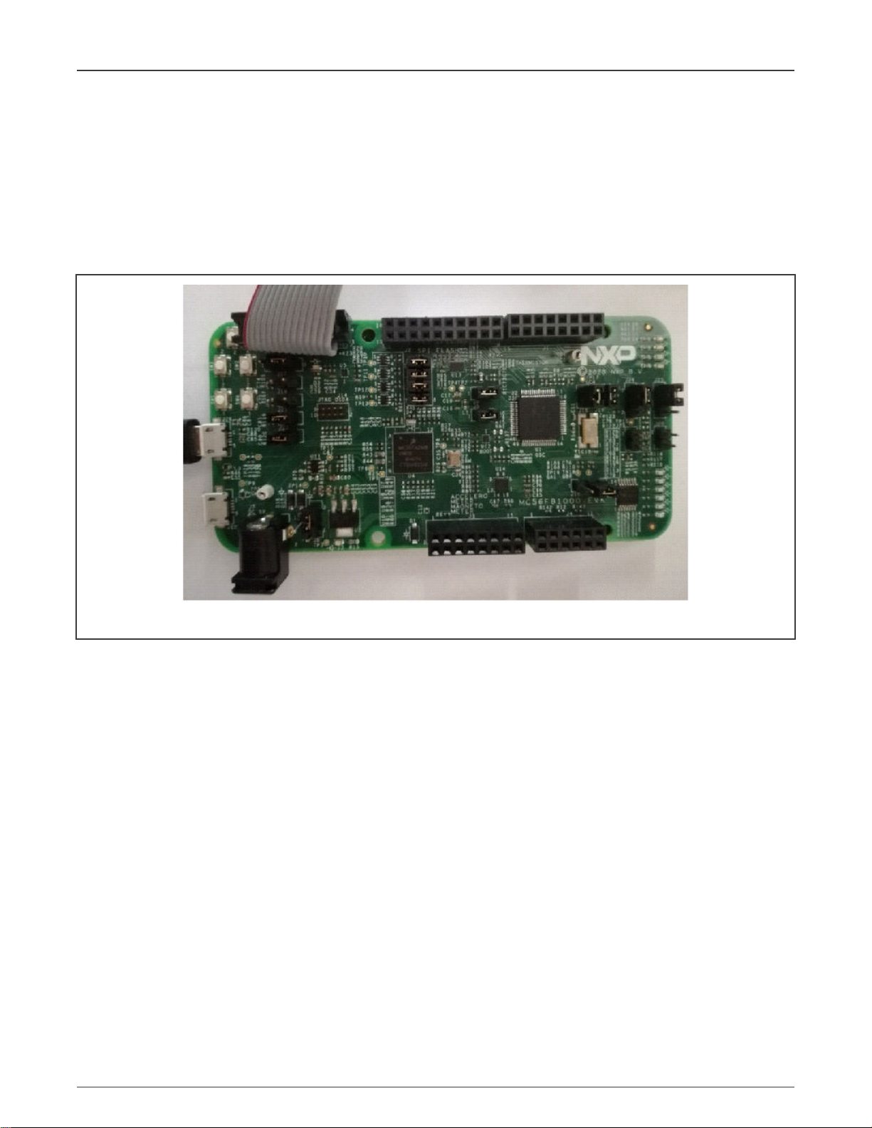
2.1 MC56F81000-EVK HW setup
Figure 1. MC56F81000-EVK development board configured for an external debug probe
• external Multilink for loading and debugging
• Micro USB -J26- for power supply and serial port communication (Silicon Labs CP210x USB to UART Bridge) !! DRIVER
INSTALATION FROM INTERNET MAY BE NEEDED !!
• default UART baud rate: 115200
Default connections for ADC test:
• GPIO pin A4 configured as ANA4 channel, connected to 4th pin of J4 connector. Use a wire to connect to VDD voltage,
for example 8th pin of J3 connector
• GPIO pin A5 configured as ANA5 channel, connected to 6th pin of J4 connector. Use a wire to connect to GND, for
example 12th pin of J3 connector
IEC60730 DSC Example v4.1, Rev. 0, 03/2021
User's Guide 4 / 14
Page 5
NXP Semiconductors
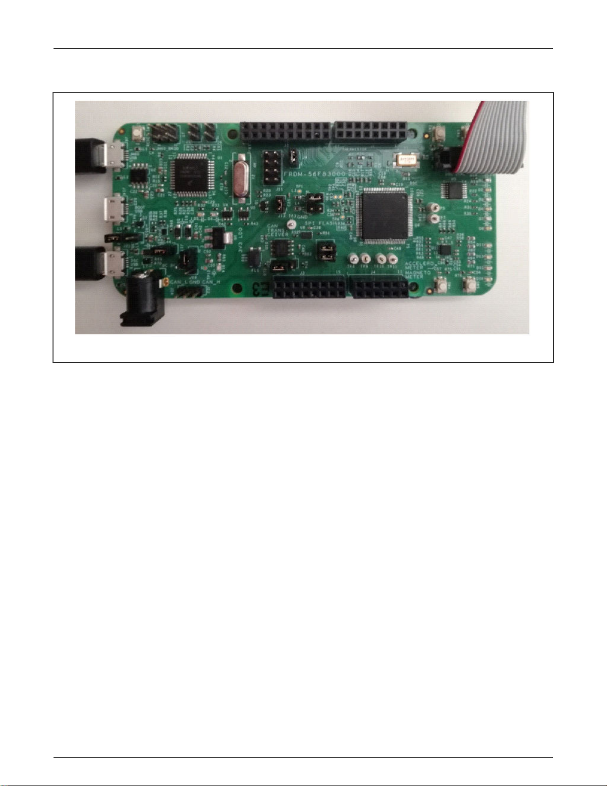
2.2 FRDM-56F83000 hardware setup
Hardware setup
Figure 2. FRDM-MC56F83000 development board configured for an external debug probe
• External Multilink for loading and debugging
• Micro-USB J21 for the power supply
• Default UART baud rate of 115200
• Micro-USB J8 for the serial port communication
The default connections for the ADC test are as follows:
• The GPIO pin A4 is configured as the ANA4 channel, connected to the 4th pin of connector J4. Use a wire to connect the
VDD voltage, for example the 8th pin of connector J3.
• The GPIO pin A5 is configured as the ANA5 channel, connected to the 6th pin of connector J4. Use a wire to connect the
GND, for example the 12th pin of connector J3.
IEC60730 DSC Example v4.1, Rev. 0, 03/2021
User's Guide 5 / 14
Page 6

NXP Semiconductors
Chapter 3
Opening the project
When the toolchain is prepared, add the project from the downloaded package into your workspace. Click on the “import project”
icon in the commander menu and then the “Browse” option in the “Select root directory” list. Navigate to the downloaded and
unpacked folder. Go to the “boards/your board” file and click the “OK” button. The example project for the selected board shall
appear in the “Projects” window.
Leave the “Copy projects into workspace” and “Add project to working sets” options unchecked and click the “Finish” button.
Now the "safety_iec60730b : flash_ldm_lpm_debug" project appears in the "Projects" window in your workspace. After building
the project, the
safety_iec60730.elf
binary file is created and the project is ready to be loaded into your device.
IEC60730 DSC Example v4.1, Rev. 0, 03/2021
User's Guide 6 / 14
Page 7

NXP Semiconductors
Chapter 4
Project files structure
The example project is a simple application which demonstrates the use of IEC60730 safety tests. The
with the initialization (after-reset) and runtime parts. The runtime part consists of an endless loop (background) and a periodical
interrupt routine. All these project parts are used to call safety test routines or their handling functions, respectively.
main.c
file is a central file
4.1 Files engaged in safety tests
safety_config.h
main.c
– central file, contains references from the linker file, global variables definition, and software loops
safety_dsc.c
safety_dsc.h
IEC60730_DSC_Class_B_CW_v4.1.lib
safety/…
project_setup_mcXXXXX.c
project_setup_mcXXXXX.h
safety_test_items.c
safety_test_items.h
MCXXXXXXXX_Internal_PFlash_LDM.cmd
– header file with general configurations for safety tests and the application.
– handling functions for the safety tests; contains references from the linker and global variables' definitions
– header file for the
– folder with library header files and the remaining source files
– configuration of the GPIO pins used for the digital input/output tests
– header file for the
safety_dsc.c
– configuration of peripherals that are related to the safety tests
– header file for the
file
– precompiled binary file with the IEC60730 Class B tests
project_setup_mcXXXXX.c
safety_test_items.c
– linker configuration file
file
file
IEC60730 DSC Example v4.1, Rev. 0, 03/2021
User's Guide 7 / 14
Page 8

NXP Semiconductors
Chapter 5
Project configuration
For a basic setup, use the
make sure that the WATCHDOG_ENABLED and WATCHDOG_TEST_ON macros are not defined. It is recommended to leave
the SAFETY_ERROR_ACTION macro value at zero. Otherwise, if any safety tests recognize an error, it is most probably due to
incorrect setup and the software becomes stuck in an endless loop.
safety_config.h
file. When starting, turn off the watchdog test and also the watchdog itself. To do so,
5.1 Linker configuration
Some of the key project configurations are made in the CMD file.
NOTE
The names of the symbols from the CMD file that are referenced in the application start with a capital "F" letter. In
the application code, they are referenced without the "F" letter.
5.1.1 Placing variables into a dedicated section
Placing the selected variables into a specific section in RAM can look as follows:
• In the CMD file, place a definition of your own section into the field that specifies the RAM area:
F_safety_ram = .;
* (.safety_ram.data)
. = ALIGN(4);
F_end_safety_ram = .;
• Reference and fill the section in the application code:
#pragma define_section safety_ram ".safety_ram.data" RW
#pragma section safety_ram begin
cop_test_t g_sSafetyCopTest;
crc_config_t sCrcConfig;
safety_common_t g_sSafetyCommon;
fs_clock_test_t g_sSafetyClockTest;
#pragma section safety_ram end
5.1.2 Placing a linkable object into RO memory
In this case, this technique is used for the Program Counter test. It is necessary to choose a valid, available, and accessible part
of memory, where the linkable object file will be placed and recognized by the application.
• Define and place the section using the CMD file:
PC_test_address_1 = 0x05555;
…
PC_test_address_1 = .;
*(.pc_test_1.text)
This definition allows for a specific placement of the
iec60730b_dsc_pc_object2.c
file.
iec60730b_dsc_pc_object1.c
file. The same approach is repeated for the
IEC60730 DSC Example v4.1, Rev. 0, 03/2021
User's Guide 8 / 14
Page 9

NXP Semiconductors
Project configuration
5.1.3 Calculating CRC of specified part of binary file before loading into device
This is a very useful feature, widely used in safety-related applications. The CodeWarrior linker allows you to configure such
calculation in the CMD file.
Fstart_text = . ; # calculate CRC from ...
…
Fend_text = .; # ... calculate CRC to
Fg_crc_linker = CRC16(Fstart_text, Fend_text,0x1021);
Fstart_text
and
Fend_text
bind the area for which the CRC is calculated.
The reference in the application code is as follows:
extern __pmem CRC16_record g_crc_linker;
extern uint32_t start_text;
extern uint32_t end_text;
5.1.4 Stack overflow and underflow test
The stack overflow and underflow test is a part of the safety library. It is an additional test that watches the application stack for
the overflow and underflow situations.
In the CMD file, an optionally wide test area is defined below and above the stack.
_min_stack_size = 0x00000100;
F_stack_test_block_size = 0x8;
F_stack_test_p_1 = _HEAP_END + 1;
F_stack_test_p_2 = F_stack_test_p_1 + F_stack_test_block_size;
. = F_stack_test_p_2;
. = ALIGN(4);
_stack_addr = . + 1;
....
. = _stack_end;
F_stack_test_p_3 = _stack_end + 1;
F_stack_test_p_4 = F_stack_test_p_3 + F_stack_test_block_size;
. = F_stack_test_p_4 + 1;
The symbols are then referenced in the application code.
extern uint16_t _stack_test_p_2; /* symbol from Linker command file */
extern uint16_t _stack_test_p_3; /* symbol from Linker command file */
These are the basic linker configurations that are used in the "safety_iec60730b" example project. For more information see the
library user's guide.
5.2 MCUXpresso configuration tool
The example project is compatible with the MCUXpresso configuration tool. The setup of pins and clocks was done using this tool.
The configuration MEX file is in the project folder. For more information, see the MCUXpresso configuration tool pages.
IEC60730 DSC Example v4.1, Rev. 0, 03/2021
User's Guide 9 / 14
Page 10

NXP Semiconductors
Chapter 6
Loading project into device and debugging
When the project is ready and the binary ELF file is built, you can load the software into the device. Click "Run>Debug Configurations" and choose the most suitable configuration from the left-hand side window. In our case, it is
"***flash_ldm_lpm_debug_PnE U-MultiLink". Then click the "Debug" icon. To become more familiar with the example project,
standard debugging features can be used. If the watchdog test is enabled (WATCHDOG_TEST_ON is defined), the watchdog
resets the processor and the debugger loses the connection. When debugging, the watchdog test must be disabled.
6.1 FreeMASTER monitoring
Download and install FreeMASTER v3.x from www.nxp.com/freemaster.
For a correct hardware setup, see Hardware setup.
Open the
• Set the correct port and speed in "Project->Options->Comm", under "RS232".
• Check if the correct ELF file is selected in "Project->Options->MAP Files". See Figure 3.
safety_iec60730b.pmpx
file from the project folder.
Figure 3. Freemaster options window
• Click the “OK” button and then the green “GO!” button.
In the "Variable Watch" window, you shall see some variables with their values.
IEC60730 DSC Example v4.1, Rev. 0, 03/2021
User's Guide 10 / 14
Page 11

NXP Semiconductors
Loading project into device and debugging
To add or remove monitored variables, click "Project->Variables->Generate" and select the variables to be added to the
"Watch" window.
Move the mouse cursor anywhere into the "Variable Watch" window, right click, and select "Watch properties". By moving from
the "Available variables" window to the "Watched variables" window, the desired variables become monitored.
IEC60730 DSC Example v4.1, Rev. 0, 03/2021
User's Guide 11 / 14
Page 12

NXP Semiconductors
Chapter 7
Support
1. Main pages about the IEC60730 safety test routines https://nxp.com/iec60730
2. MC56F81000-EVK evaluation board https://www.nxp.com/design/software/development-software/development-board-
for-mc56f81xxx-digital-signal-controllers:MC56F81000-EVK
3. MC56F83000-EVK evaluation board https://www.nxp.com/design/development-boards/freedom-development-boards/
mcu-boards/development-board-for-mc56f83xxx-digital-signal-controllers:MC56F83000-EVK
4. CodeWarrior IDE development tools https://www.nxp.com/design/software/development-software/codewarrior-
development-tools:CW_HOME
5. FreeMASTER visualization tool https://nxp.com/freemaster
6. MCUXpresso configuration tools https://www.nxp.com/design/software/development-software/mcuxpresso-software-
and-tools-/mcuxpresso-config-tools-pins-clocks-peripherals:MCUXpresso-Config-Tools
7. NXP Community; if you have not found the answer to your question https://community.nxp.com/
IEC60730 DSC Example v4.1, Rev. 0, 03/2021
User's Guide 12 / 14
Page 13

NXP Semiconductors
Chapter 8
Revision history
Table 1. Revision history
Revision number Date Substantive changes
0 03/2021 Initial release
IEC60730 DSC Example v4.1, Rev. 0, 03/2021
User's Guide 13 / 14
Page 14

How To Reach Us
Home Page:
nxp.com
Web Support:
nxp.com/support
Information in this document is provided solely to enable system and software implementers to use NXP products. There
are no express or implied copyright licenses granted hereunder to design or fabricate any integrated circuits based on the
information in this document. NXP reserves the right to make changes without further notice to any products herein.
NXP makes no warranty, representation, or guarantee regarding the suitability of its products for any particular purpose, nor
does NXP assume any liability arising out of the application or use of any product or circuit, and specifically disclaims any
and all liability, including without limitation consequential or incidental damages. “Typical” parameters that may be provided
in NXP data sheets and/or specifications can and do vary in different applications, and actual performance may vary over
time. All operating parameters, including “typicals,” must be validated for each customer application by customer's technical
experts. NXP does not convey any license under its patent rights nor the rights of others. NXP sells products pursuant to
standard terms and conditions of sale, which can be found at the following address: nxp.com/SalesTermsandConditions.
Right to make changes - NXP Semiconductors reserves the right to make changes to information published in this
document, including without limitation specifications and product descriptions, at any time and without notice. This
document supersedes and replaces all information supplied prior to the publication hereof.
Security — Customer understands that all NXP products may be subject to unidentified or documented vulnerabilities.
Customer is responsible for the design and operation of its applications and products throughout their lifecycles to reduce
the effect of these vulnerabilities on customer’s applications and products. Customer’s responsibility also extends to other
open and/or proprietary technologies supported by NXP products for use in customer’s applications. NXP accepts no
liability for any vulnerability. Customer should regularly check security updates from NXP and follow up appropriately.
Customer shall select products with security features that best meet rules, regulations, and standards of the intended
application and make the ultimate design decisions regarding its products and is solely responsible for compliance with all
legal, regulatory, and security related requirements concerning its products, regardless of any information or support that
may be provided by NXP. NXP has a Product Security Incident Response Team (PSIRT) (reachable at PSIRT@nxp.com)
that manages the investigation, reporting, and solution release to security vulnerabilities of NXP products.
NXP, the NXP logo, NXP SECURE CONNECTIONS FOR A SMARTER WORLD, COOLFLUX,EMBRACE, GREENCHIP,
HITAG, ICODE, JCOP, LIFE, VIBES, MIFARE, MIFARE CLASSIC, MIFARE DESFire, MIFARE PLUS, MIFARE FLEX,
MANTIS, MIFARE ULTRALIGHT, MIFARE4MOBILE, MIGLO, NTAG, ROADLINK, SMARTLX, SMARTMX, STARPLUG,
TOPFET, TRENCHMOS, UCODE, Freescale, the Freescale logo, AltiVec, CodeWarrior, ColdFire, ColdFire+, the Energy
Efficient Solutions logo, Kinetis, Layerscape, MagniV, mobileGT, PEG, PowerQUICC, Processor Expert, QorIQ, QorIQ
Qonverge, SafeAssure, the SafeAssure logo, StarCore, Symphony, VortiQa, Vybrid, Airfast, BeeKit, BeeStack, CoreNet,
Flexis, MXC, Platform in a Package, QUICC Engine, Tower, TurboLink, EdgeScale, EdgeLock, eIQ, and Immersive3D are
trademarks of NXP B.V. All other product or service names are the property of their respective owners. AMBA, Arm, Arm7,
Arm7TDMI, Arm9, Arm11, Artisan, big.LITTLE, Cordio, CoreLink, CoreSight, Cortex, DesignStart, DynamIQ, Jazelle,
Keil, Mali, Mbed, Mbed Enabled, NEON, POP, RealView, SecurCore, Socrates, Thumb, TrustZone, ULINK, ULINK2,
ULINK-ME, ULINK-PLUS, ULINKpro, μVision, Versatile are trademarks or registered trademarks of Arm Limited (or its
subsidiaries) in the US and/or elsewhere. The related technology may be protected by any or all of patents, copyrights,
designs and trade secrets. All rights reserved. Oracle and Java are registered trademarks of Oracle and/or its affiliates. The
Power Architecture and Power.org word marks and the Power and Power.org logos and related marks are trademarks and
service marks licensed by Power.org.
©
NXP B.V. 2021. All rights reserved.
For more information, please visit: http://www.nxp.com
For sales office addresses, please send an email to: salesaddresses@nxp.com
Date of release: 03/2021
Document identifier: IEC60730DSCE41UG
 Loading...