

IP MIGRATION MADE SIMPLE
NVT PHYBRIDGE
NV-EC-1701U
Eo2™ Ethernetover 2-wire
Transceiver with PoE+
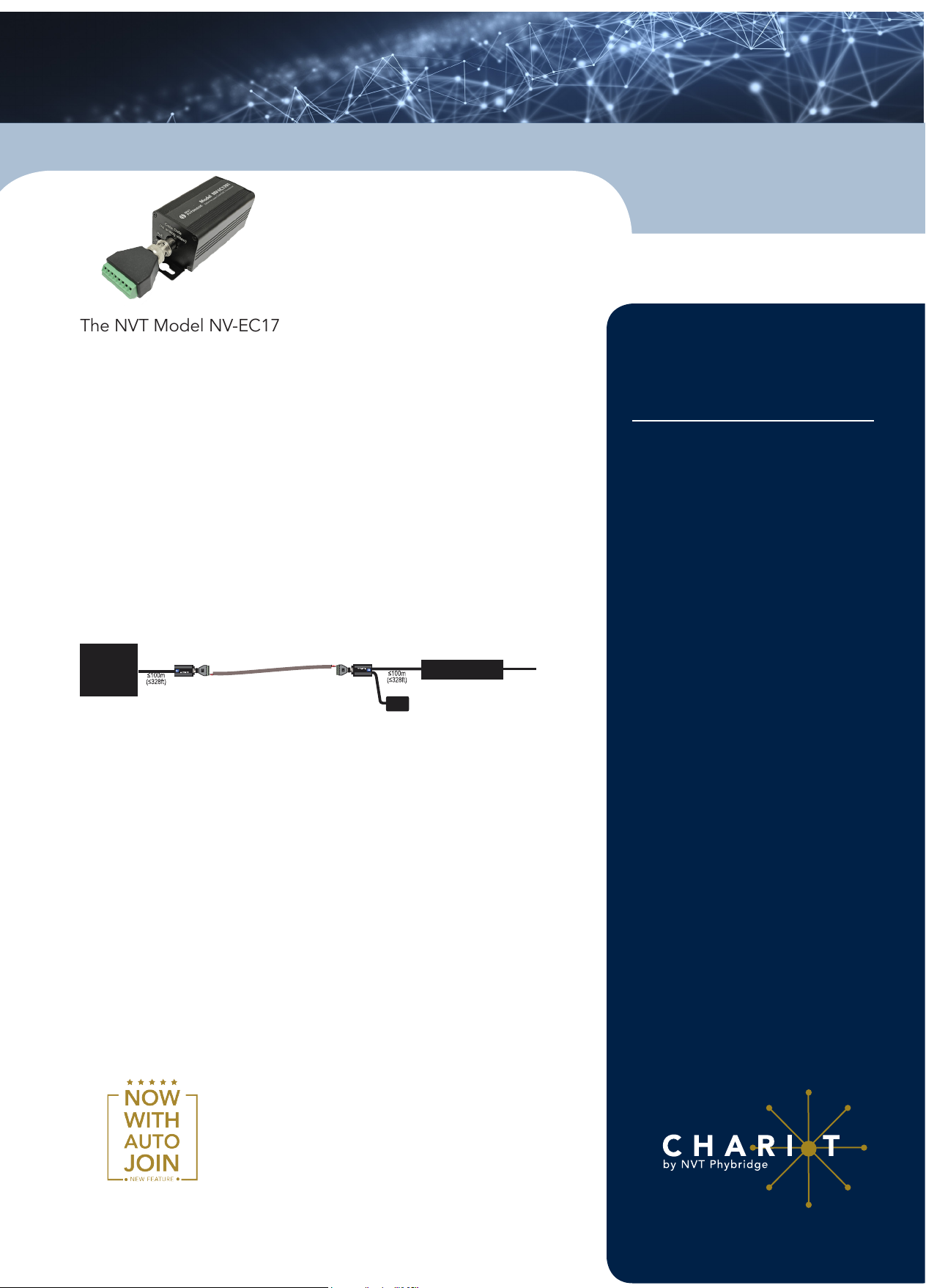
Model NV-EC1701U
The NVT Model NV-EC1701U Ethernet over 2-wire Transceiver is
a compact media converter that allows 10/100 BaseT Ethernet
and PoE+ power to be transmitted using ordinary 2-wire cable.
These devices are often used in legacy installations where existing
cable is re-deployed as part of an upgrade to IP cameras. 55 VDC
class 2 power is delivered to one transceiver, which distributes it
to multiple* remote transmitters, and their PoE, PoE+, or High
Power PoE cameras*.
These transceivers are extremely simple to use, with no IP or
MAC addressing required. Status LEDs indicate power and link
connectivity/activity for each port. They are backed by NVT
Phybridge’s award winning customer support and limited lifetime
warranty.
Application Example:
6 Watt
IP Camera
Door Access
or other IP device
NV-EC1701U
Cat5
Model NV-EC1701
EthernetoverC oax Transceiver
www 208 977 6614
2-wire Cable
NV-EC1701U
www (0) 2089776614
Ethernet over CoaxTransceiver
Model NV-EC1701
Cat5
Ethernet Switch
55 VDC Power Supply
LAN /W AN
Features
• 100 BaseT transmission; Network speeds up to 93 Mbps*; Up
to 1,000ft (305m)*
• 55 VDC is distributed over the coax to all connected equipment
• One NVT Eo2™ transceiver at the network-end can support
multiple* remote Eo2™ transceivers and connected devices
• Up to four Eo2™ transceivers can be rack mounted on an
NV-RMEC16U Eo2™ Rack Mount Tray Kit, connecting up to
16 entry stations or other devices
• Transparently supports all networking protocols (UDP, TCP/IP,
HTTP, Multicast*, etc.)
• 128-bit AES encrypted transmission
• Available in 1-4 device Eo2™ System Kits
• Limited lifetime warranty
DATA SHEET
NV-EC1701U
Advantages
• Transmit 10/100 BaseT
Ethernet up to 1,000ft
(305m)* over 4-pair cat5;
750ft (228m) over 18/2
(or similar 2-wire cable);
500ft (150m) over Shielded
Twisted-Pair
• Easy conguration, no PC
required
• Powers PoE, PoE+, or High
Power PoE cameras (or
other PoE devices), up to
50 watts*
• Built-in transient
protection; Industrial
temperature range
*Distance and number of devices supported may
be lower due to power supply capacity and wire
voltage-drop. See Wire Distance Charts on page 4.
Bandwidth is dynamically allocated. Multicast requires an IGMP
Querier within your network switch. High bandwidth streaming
devices (>15Mbps) that employ unusually “chatty”protocols
(TCP/IP, TFTP, etc.) are not recommended. Use RTP/UDP instead.

NVT PHYBRIDGE
NV-EC1701U
DATA SHEET
EC-1701U Technical Specifications
RJ45 Ethernet Interface
Connectivity
Wire Type
Distance
Speed
Latency
Throughput
Power
Output
RJ45, auto-crossover
Cat5 or better
Up to 328ft (100m)
10/100 Base T, half/full duplex, auto-neogitation
auto MDI/MDIX cross-over
3mS
85Mbps ±10% useable bandwidth per network
Data
Example: Four megapixel cameras, all sharing
one coax network, each sending 20Mbps video
stream(s).
This Power Sourcing Equipment (PSE) supports
Powered Devices (PDs) that are compatible with
IEEE 802.3af/at or PDs that draw up to 50 watts*.
For maximum power/distance, 55 VDC appears on
all eight RJ45 pins, and are current-protected and
transient-protected.
2-Wire Building Wiring Interface
Connectivity
Impedance
Distance
Topology
Transmission
Technology
16.5W
25 to 100Ω
See page 4
Bus architecture supports star, daisy-chain, or any
combination. One control-room NV-EC1701U may
support multiple remote NV-EC1701Us.
IEEE 1901, 128-bitAES encryption
LED Status Indicators
Power
BNC/2-wire Interface
RJ45 Interface
Blue “Power On”
Green “Link
Green “Link”
Power Consumption
Consumption Per Transceiver
Generated Heat
≤ 3.0 W @ 10 to 55 VDC
10 BTU/Hour
Regulatory
UL Listed to IEC/UL 60950-1 Complies with FCC
part 15A limits
Warranty
Limited Lifetime
*Important Note: Distance will often be shorter due to power supply capacity and wire voltagedrop. See Maximum Per-Camera Wire Distance Chart on Page 4.
WARNING: For safety, never use more than two power supplies. Never exceed 120 watts.
BNC
On when
Link detected
LED Status
Indicators
Flashes with
Data
Power
Flashes when
initializing or
Joining
RJ45
On when
connected
Flashes with
Data
Mechanical/Environmental
Transceiver
Dimensions
Transceiver
Weight
Operating
and Storage
Temperature
Transient
Immunity
5.1 in (131mm) long x 1.3 in (33mm) high x 1.5 in
Body
(38mm) wide
(excluding connectors and NV-BNCA adaptor)
0.32lb (145g)
40°F to 185°F (-40°C to +85°C)
20 to 85% RH non-condensing
5x20µS 3000A, 6000V ESD 20KV, 200pF
Power Supply
Power supplies are external inline, with an
IEC380-C14 power inlet and a 6ft (1.18m) line
cord. Input voltage is 100~240VAC 50/60Hz. A
molded P1J 5.5mm barrel connector provides
+55VDC
a class 2 (SELV) regulated output with one of
these ratings:
55V 60W
Model NV-PS55-60W
Model NV-PS55-110W
Operating/Storage
Temperature
Transient Immunity
Use only the power cord provided with the unit or equivalent UL
approved type SPT-2, SVT, or SJT 18/3 AWG 100~240 VAC, 1 Amp
60°C max 15 ft (4.5 m) long. One end with IEC380-C13 appliance
coupler and the other end with NEMA 1015P or equivalent for your
country.
Power
Output
Specications subject to change without notice
5.2 in (132 mm) long x 2.3 in (58 mm)
wide x 1.2 in (30 mm) high
0.68 lb (0.31 Kg) shipping weight
55V 110W
5.9 in (150 mm) long x 2.3 in (58 mm)
wide x 1.4 in (36 mm) high
0.90 lb (0.41 Kg) shipping weight
-40°F to +185°F (-40°C to +85°C
20 to 5% relative humidity noncondensing)
5 x 20µS 3,000A, 6,000V ESD 20KV,
200pF
This Power Sourcing Equipment (PSE)
supports Powered Devices (PDs) that
are compatible with IEEE 802.3af/at
or PDs that draw up to 50 watts*. For
maximum power/distance, 55 VDC
appears on all eight RJ45 pins, and
are current-protected and transientprotected.
for more information visit www.nvtphybridge.com

NVT PHYBRIDGE
NV-EC1701U
DATA SHEET
NV-EC1701U Transceiver Kits
Single 60 Watt Eo2 Transmission System
NV-EC1701U-KIT1:
• 2: NV-EC1701U Transceivers
• 1: NV-PS55-60W Power Supply with IEC line cord
• 2: NV-PC4PR patch-cord
Single 110 Watt Eo2 Transmission System
NV-EC1701U-K1H:
• 2: NV-EC1701U Transceivers
• 1: NV-PS55-110W Power Supply with IEC line cord
• 2: NV-PC4PR patch-cord
Dual 60 Watt Eo2 Transmission System
NV-EC1701U-KIT2:
• 3: NV-EC1701U Transceivers
• 1: NV-PS55-60W Power Supply with IEC line cord
• 3: NV-PC4PR patch-cord
Dual 110 Watt Eo2 Transmission System
NV-EC1701U-K2H:
• 3: NV-EC1701U Transceivers
• 1: NV-PS55-110W Power Supply with IEC line cord
• 3: NV-PC4PR patch-cord
Triple 60 Watt Eo2 Transmission System
NV-EC1701U-KIT3:
• 4: NV-EC1701U Transceivers
• 1: NV-PS55-60W Power Supply with IEC line cord
• 4: NV-PC4PR patch-cord
Dual 110 Watt Eo2 Transmission System
NV-EC1701U-K2H:
• 4: NV-EC1701U Transceivers
• 1: NV-PS55-110W Power Supply with IEC line cord
• 4: NV-PC4PR patch-cord
Quadruple 60 Watt Eo2 Transmission System
NV-EC1701U-KIT4:
• 5: NV-EC1701U Transceivers
• 1: NV-PS55-60W Power Supply with IEC line cord
• 5: NV-PC4PR patch-cord
Quadruple 110 Watt Eo2 Transmission System
NV-EC1701U-K4H:
• 5: NV-EC1701U Transceivers
• 1: NV-PS55-110W Power Supply with IEC line cord
• 5: NV-PC4PR patch-cord
NV-EC1701U Accessories
NV-PS55-60W
NV-PS55-110W
55VDC power supply, 60 watts with IEC line cord
55VDC power supply, 110 watts with IEC line cord
NV-BNCA
NV-PC4PR
NV-DPSC4
NV-RMEC16U
BNC Screw terminal adaptor
RJ45 Patch Cord, 4-pair 3’ (1m) Grey
Detachable Power Supply Cord Splitter 1:4 2ft
Rack mounting chassis, 19” x 1U
Holds up to 4 NV-EC1701U transceivers plus 60W or 110W power supplies.
Includes NV-DPSC4 Power Cord Splitter (Transceivers and power supplies not
included)
for more information visit www.nvtphybridge.com

NVT PHYBRIDGE
m
m
1
C
2
3
o
h P wr
gh
ower
NV-EC1701U
DATA SHEET
NV-EC1701U Power Data Distance Chart
The distance capability of wire is dependant on its ability to deliver DC power, and separately, to deliver high-frequency
data signals.
The graph below shows maximum power delivery when using a 55V power supply. If you are locally powering your
camera (or other remote device), then this graph does not apply.
PoE devices require a minimum of 43V to operate. With a 55V supply, we have up to 13V of allowable voltage drop on
the wire.
The voltage will dip in proportion to the remote (camera) load. The graph below shows what PoE power distances are
supported for various loads and wire types.
• Start with the camera wattage at the left. Sometimes IP cameras are listed as to their PoE Class rather than wattage.
• Now read over to the right until you nd your kind of wire. Then look up (feet) or down (meters) to nd your maximum
distance.
• If your wire is not among the examples, simply measure its total resistance and nd the value on the right side of the
graph. The maximum supported wattage is on the left.
• There are a wide variety of wire qualities. The graph below will help you determine your data throughput as a function
of wire type and distance.
131 ft
164 ft
98 ft
197 ft
50 W
40 W
30 W
Camera Wattage
25 W
20 W
18 W
15 W
12 W
10 W
8.0 W
6.0 W
5.0 W
4.0 W
3.0 W
2.5 W
2.0 W
0 W
30 m
40 m
50 m
60 m
NV-EC1701U Power Data Distance
262 ft
328 ft
397 ft
492 ft
590 ft
656 ft
C
a
t
6
2
3
C
A
a
W
t
5
G
2
4
1
P
A
r
W
G
1
P
r
80 m
100 m
120 m
150 m
180 m
200 m
820 ft
984 ft
250 m
300 m
1,312 ft
1,640 ft
C
a
t
6
4
P
1
r
8
/
2
o
r
C
a
t
5
Data Limited
Data Limited
400 m
500 m
1,968 ft
4
P
r
600 m
2,624 ft
3,280 ft
3,936 ft
800 m
1,000 m1,200 m1,500 m1,800 m2,000
4,920 ft
5,904 ft
6,560 ft
13,120 ft
8,200 ft
9,840 ft
16,400 ft
3
4
6
7
9
11
12
14
16
19
21
23
24
28
2,500 m3,000 m4,000 m5,000
38
Total Wire Resistance
for more information visit www.nvtphybridge.com
 Loading...