


Complete Installation Guide
Model NV-EC1701U
EoC Ethernet over Coax Transceiver
with PoE, PoE+, or High Power PoE
SAFETY WARNINGS AND PRECAUTIONS
Access to the interior of this unit shall be made only by
a qualied technician.
To ensure adequate cooling of the equipment, a 2-inch
unobstructed space must be provided around all sides
of the unit.
To prevent the risk of shock or re hazard, replace fuse
with same type and rating.
Der Zugang ins Innere des Gerätes ist nur einem
fachlich qualizierten Techniker gestattet.
Um die Kühlung des Gerätes nicht zu beeinträchtigen,
ist es notwendig, an allen Seiten des Gerätes ca 5 cm
Raum zu lassen.
Zur Vermeidung der Stromschlag-und Feuergefahr
beim Auswechseln Sicherungen des gleichen Typs und
der gleichen Nennleistung einsetzen.
Seul un spécialiste doit avoir accès l’appareil.
An de ne pas nuire au processus de refroidissement, il
est nécessaire de laisser un espace d’environ 5 cm de
chaque côté de l’appareil.
An d’éviter tout risque d’incendie ou d’électrocution,
remplacez les fusibles par des fusibles de même type
et de même ampérage.
El acceso al interior de esta unidad deberá ser realizado
únicamente por un técnico cualicado.
Para asegurar un enfriamiento adecuado del equipo, se
debe proporcionar un espacio sin obstrucciones de 2
pulgadas alrededor de todos los lados de la
unidad.
Para evitar el riesgo de choque o peligro de incendio,
reemplace el fusible con el mismo tipo y clasicación.
L’accesso all’interno di questa unità `deve essere
eettuata solo da un tecnico qualicato.
Per garantire un adeguato rareddamento
dell’apparecchiatura, uno spazio libero da 2 pollici deve
essere fornita intorno a tutti i lati dell’unità.
Per evitare che la prevenzione del rischio di scossa o
di pericolo di incendio, sostituire il fusibile con lo stesso
tipo e valore.
Достъп до вътрешността на този уред трябва да се
извършва само от квалифициран техник.
За да се осигури подходящо охлаждане на
оборудването, трябва да се осигури 2-инчово
свободно пространство около всички страни на
устройството.
За да предотвратите опасност от удар или
пожар, сменете предпазителя със същия тип и
квалификация.
Juurdepääs interjööri selle üksuse tehakse ainult
kvalitseeritud tehnik.
Jahutuse tagamiseks seadme, 2-tolline vaba ruum
peab olema ümber kõik küljed üksus.
Selleks, et vältida riski ning tulekahjuoht, vaheta kaitse
sama tüüpi ja hinnang.
Η πρόσβαση στο εσωτερικό της μονάδας πρέπει να
γίνεται μόνο από εξειδικευμένο τεχνικό.
Για να εξασφαλιστεί η κατάλληλη ψύξη του εξοπλισμού,
πρέπει να υπάρχει ένας ελεύθερος χώρος 2 ιντσών
γύρω από όλες τις πλευρές της μονάδας.
Για να αποφύγετε τον κίνδυνο κρούσης ή πυρκαγιάς,
αντικαταστήστε την ασφάλεια με τον ίδιο τύπο και την
ίδια βαθμολογία.
Piekļuve interjera šīs vienības veic tikai kvalicēts
tehniķis.
Lai nodrošinātu pietiekamu dzesēšanu iekārtu, 2 collu
aizsegts telpu jānodrošina ap visām pusēm vienības.
Lai novērstu risku, ka trieciena vai ugunsgrēka briesmas,
nomainīt drošinātāju ar tāda paša veida un reitingu.
Prieiga prie šio įrenginio viduje, turi būti atlikti tik
kvalikuotas specialistas.
Siekiant užtikrinti tinkamą aušinimą įranga, 2 colių
užgriozdinti erdvę turi būti pateikta apie visus įrenginio
pusių.
Siekiant užkirsti kelią šoko ar gaisro pavojus riziką,
pakeiskite saugiklį su tos pačios rūšies ir įvertinimas.
A készülék belsejét csak szakképzett szakember
végezheti.
A berendezés megfelelő hűtésének biztosítása
érdekében egy 2 hüvelykes, akadálytalan helyet kell
biztosítani a készülék minden oldalán.
Az ütésveszély vagy a tűzveszély elkerülése érdekében
cserélje ki az azonos típusú és minősített biztosítékot.
Toegang tot het interieur van dit toestel wordt alleen
door een gekwaliceerde technicus uitgevoerd.
Om een adequate afkoeling van de apparatuur te
garanderen, moet een 2-inch vrijstaande ruimte rondom
alle kanten van het apparaat worden aangebracht.
Om het risico op schokken of brandgevaar te voorkomen,
vervang de zekering met hetzelfde type en de waarde.
Tilgang til det indre av denne enheten skal kun utføres
av en kvalisert tekniker.
For å sikre tilstrekkelig kjøling av utstyret, må det være
2 tommers uhindret plass rundt alle sider av enheten.
For å unngå fare for støt eller brannfare, bytt sikring
med samme type og karakter.
Dostęp do wnętrza tego urządzenia wykonuje tylko
wykwalikowany technik.
W celu zapewnienia odpowiedniego chłodzenia
urządzenia, wokół wszystkich stron urządzenia musi
być umieszczona 2-calowa przestrzeń bez przeszkód.
Aby uniknąć ryzyka porażenia prądem lub pożaru,
wymień bezpiecznik na ten sam typ i poziom.
Page 1 of 14
888.901.3633 | +44 (0) 208 977 6614
www.nvtphybridge.com
Copyright © 2017 NVT Phybridge
2017/11

Complete Installation Guide
Model NV-EC1701U
EoC Ethernet over Coax Transceiver
with PoE, PoE+, or High Power PoE
SAFETY WARNINGS AND PRECAUTIONS
O acesso ao interior desta unidade deve ser efectuado
apenas por um técnico qualicado.
Para assegurar o resfriamento adequado do
equipamento, um espaço sem obstruções de 2
polegadas deve ser fornecido em torno de todos os
lados da unidade.
Para evitar o risco de choque ou incêndio, substitua o
fusível pelo mesmo tipo e classicação.
Accesul la interiorul acestui aparat trebuie efectuat
numai de către un tehnician calicat.
Pentru a asigura o răcire adecvată a echipamentului,
trebuie prevăzut un spațiu liber de 2 inci pe toate laturile
unității.
Pentru a preveni riscul de șoc sau de pericol de
incendiu, înlocuiți siguranța cu același tip și clasicare.
Dostop do notranjosti te enote se izvede le strokovnjak.
Da bi zagotovili ustrezno hlajenje opreme, mora
2-palčni neoviran prostor, je treba zagotoviti okoli vse
strani enote.
Da bi preprečili nevarnost udara ali nevarnosti požara,
zamenjajte varovalko iste vrste in jakosti.
Přístup k vnitřku tohoto přístroje musí provádět pouze
kvalikovaný technik.
Aby bylo zajištěno přiměřené chlazení zařízení, musí
být kolem všech stran jednotky zajištěn volný prostor o
průměru 2 palce.
Abyste předešli nebezpečí úrazu nebo požáru, vyměňte
pojistku stejného typu a typu.
Aðgangur að innanverðu þessa eininga skal aðeins
gerð af viðurkenndum tæknimanni.
Til að tryggja fullnægjandi kælingu búnaðarins verður
að vera með 2 tommu óhindrað pláss fyrir alla hliðum
tækisins.
Til að koma í veg fyrir hættu á losti eða eldhættu skal
skipta um öryggi með sömu tegund og einkunn.
Aċċess għall-intern ta ‘din l-unità għandha ssir biss
minn tekniku kkwalikat.
Biex jiġi żgurat tkessiħ adegwat tat-tagħmir, 2-pulzier
spazju mhux mxkel għandhom ikunu provduti madwar
naħat kollha tal-unità.
Biex ikun evitat ir-riskju ta ‘xokk jew perikolu ta’ nar,
jissostitwixxu fjus bil istess tip u ratika.
Adgang til det indre af denne enhed skal kun foretages
af en kvaliceret tekniker.
For at sikre tilstrækkelig afkøling af udstyret skal der
være en 2-tommers uhindret plads på alle sider af
enheden.
For at undgå risiko for stød eller brandfare udskiftes
sikringen med samme type og rating.
Prístup do interiéru tohto prístroja môže vykonať iba
kvalikovaný technik.
Aby bolo zabezpečené dostatočné chladenie
zariadenia, musí byť okolo všetkých strán jednotky k
dispozícii 2-palcový neobmedzený priestor.
Aby ste zabránili nebezpečenstvu výbuchu alebo
požiaru, vymeňte poistku rovnakého typu a typu.
Tämän laitteen sisätilojen saa suorittaa ainoastaan
pätevä teknikko.
Laitteen riittävän jäähdytyksen varmistamiseksi on
järjestettävä 2 tuuman esteettömät tilat laitteen kaikkien
puolien ympärille.
Vaihda sulake saman tyyppisellä ja luokalla, jotta iskun
tai tulipalon vaara ei onnistu.
Tillgång till det inre av denna enhet ska endast utföras
av en kvalicerad tekniker.
För att säkerställa tillräcklig kylning av utrustningen
måste ett 2-tums fritt utrymme tillhandahållas runt alla
sidor av enheten.
För att undvika risk för chock eller brandfara, byt ut
säkring med samma typ och betyg.
Page 2 of 14
888.901.3633 | +44 (0) 208 977 6614
www.nvtphybridge.com
Copyright © 2017 NVT Phybridge
2017/11

Complete Installation Guide
Model NV-EC1701U
EoC Ethernet over Coax Transceiver
with PoE, PoE+, or High Power PoE
PRODUCT OVERVIEW
• Transmit 10/100 BaseT Full Duplex Ethernet up to 1,000ft (305m)* over 4-pair cat5;
750ft (228m) over 18/2 (or similar 2-wire cable); 500ft (150m) over Shielded Twisted Pair
• Powers PoE entry stations (or other PoE, PoE+, or High Power devices), up to 60
watts*
• 55VDC is distributed over 2-wire cable to all connected IP devices
• One NVT Eo2TM transceiver at the network-end can support multiple remote
Eo2TM transceivers and connected devices
• Up to four Eo2TM transceivers can be rack mounted on an NV-RMEC16U-90
Eo2TM Rack Mount Tray Kit, connecting up to 16 entry stations or contact closures
• Easy conguration, no PC required
• Transparently supports all networking protocols (UDP, TCP/IP, HTTP, Multicast etc.)
• Advanced 128-bit AES encrypted transmission and PoE+ power technology
• Built-in transient protection; Industrial temperature range
• Available in 1-4 device Eo2TM System Kits
• Limited lifetime warranty
The NVT Phybridge Model NV-EC1701U Eo2TM Ethernet over 2-Wire Transceiver is a
compact media converter that allows 10/100 BaseT Ethernet and PoE power to be transmitted
using UTP, STP,18/2, or similar cable. These devices are often used in legacy installations
where existing wire is re-used as part of an upgrade to IP devices. 55VDC class 2 power is
delivered to one transceiver, which distributes it to up to four remote transceivers, and their
PoE or PoE+ devices.
These transceivers are extremely simple to use, with no PC conguration required. Status
LEDs indicate power and link connectivity/activity for RJ45 and 2-wire ports. The NV-EC1701U
is backed by NVTP’s award winning customer support and limited lifetime warranty.
*Distance and number of devices supported may be lower due to attenuation/voltage-drop on the wire. See Wire Distance charts on page 9.
Page 3 of 14
888.901.3633 | +44 (0) 208 977 6614
www.nvtphybridge.com
Copyright © 2017 NVT Phybridge
2017/11
NV-EC1701U Eo2 transceivers transmit high bandwidth encrypted Ethernet signals over conventional 2-wire cables. To provide utmost signal integrity and security, the
Complete Installation Guide
Model NV-EC1701U
EoC Ethernet over Coax Transceiver
with PoE, PoE+, or High Power PoE
CONFIGURATION INSTRUCTIONS
NV-EC1701U transceivers must be configured to communicate exclusively with other transceivers within their Network Group. This group typically consists of one
NV-EC1701U located at the control room (usually connected to an ethernet switch or router), and up to four remote NV-EC1701U transceivers (usually connected to IP
cameras or other remote IP devices).
The NV-EC1701U now comes in auto join mode for easy and quick deployments. The joining process is now only required when deploying more than 1 group of NV-EC1701
units. When deploying more than 1 group (max 4 end points and 1 head end) you are required to factory default the groups after the first group. You must first factory default the
units in the next group so they can be joined together into a group. Follow the un-joining method listed below and once factory defaulted you can then move to Step 3 to join the
newly factory defaulted units together.
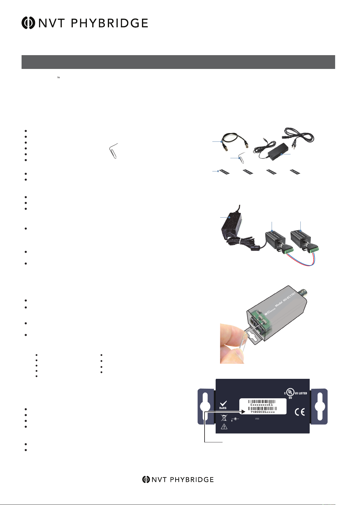
Step One: Gather Materials
Step One: Gather Materials
NV-EC1701U transceivers
55V power supply & line-cord (NV-PS55-60W)
Hook-up wire or BNC cable (not supplied)
Coax jumper
Small paper-clip, partially straightened:
Device labels
IP Network Documentation Log
Step Two: Connect Hardware
Remove and discard the “Configure Before Use” labels.
Paper-clip (slightly straightened)
NV-EC1701U transceivers
E
the
rne
t ov
er C
o
a
x Eo
C
Tr
an
sce
iv
er
E
th
e
rn
e
t ove
r C
oa
x EoC
Tra
nsceive
r
E
th
erne
t o
ve
r C
oa
x E
oC
Tran
sce
iv
e
r
Connect two NV-EC1701U transceivers using hook-up wire or a BNC cable.
Observe polarity. Units will not power-up if the polarity is reversed.
Do not connect anything to the RJ45 connector.
Connect a 55V power supply to transceiver #1; Apply power.
Verify that the blue POWER LED on each transceiver illuminates.
Before proceeding to next step, wait for any green BNC LED that came on
during start up to go off, approximately 10 seconds.
Step Three: Joining
On transceiver #1, using the straightened paper-clip to access the small
push-button located behind and slightly above the RJ45 LED.
Firmly press and release this button.
55V power supply
& line-cord
(NV-PS55-60W)
Step Two: Connect Hardware
Transceiver #1 Transceiver #2
E
the
rn
e
t o
ve
r C
o
ax
E
o
C
Tra
n
s
ce
iv
er
The blue Power LED will begin blinking.
Then firmly press and release the same push-button on transceiver #2.
The blue Power LED will begin blinking.
Both transceivers have now entered Join Mode.
They will find each other and establish encrypted communication.
In about 10 seconds, the blue Power LEDs on both transceivers will return
to a steady on condition, 'and the green BNC LEDs will illuminate indicating
a successful join.
Step Four: Adding Transceivers
(if required)
Transparent view of push-button location
Step Three:
Disconnect transceiver #2 and replace it with a new un-joined transceiver (#3, or #4, or #5).
Repeat steps two and three to add additional transceivers to the same Network Group.
Ethernet over Coax EoC
Step Five: Documentation
Label the configured transceivers with a unique Network Group ID of your choice.
This will help you identify them after they have been deployed.
Record this Network Group information in your IP Network Documentation Log.
This log may include essential documentation which will help you identify all
system devices during and after deployment:
Camera Number
Camera Position/Location
Camera Make & Model
Camera MAC & IP Address
Camera Login & Password
Camera-end NVT Phybridge Transceiver MAC Address
NVT Phybridge Transceiver Network Group Name
Control Room NVT Phybridge Transceiver MAC Address
Control Room Router Port Number
Un-Joining a Transceiver
If you need to move a transceiver from one Network Group to another, it must first un-learn its
previous Network Group and be returned to an un-joined state. Do this by performing these
steps:
Disconnect the transceiver from the old network.
Connect a 55 VDC power supply to a transceiver.
Wait until its green BNC LED is lit.
Using the straightened paper-clip to access the small push-button located behind
and slightly above the RJ45.
Press and hold this button for 10-12 seconds until all of the LEDs flash.
Release the paperclip.
Observe that the green BNC LED goes on for ten seconds and then goes off.
Un-joining is now complete. If you are not sure that un-joining has been successful,
remove and then re-apply power, and repeat.
This device complies with Part 15 of the FCC Rules. Operation is subject to the
following two conditions: (1) This device must not cause harmful interference,
and (2) this device must accept any interference
received, including interference that
may cause undesired operation.
+ 48-55 VDC 0.03 MIN - 1.6A MAX
D O N O T E X C E E D T W O P O W E R S U P P L I E S P E R S Y S T E M
C L A S S 2 O N LY ( S E LV )
Step Five: Transceiver MAC Address
55V power supply
& line-cord
E
th
e
rn
et o
Transceiver
MADE IN ROK
ver C
o
ax
EoC
Tran
s
ce
ive
r
E
th
e
rn
I.T.E
E344963
et o
v
e
r C
o
a
x E
o
C
Tran
s
ce
ive
r
(NV-PS55-60W)
Observe
polarity
Page 4 of 14
888.901.3633 | +44 (0) 208 977 6614
www.nvtphybridge.com
Copyright © 2017 NVT Phybridge
2017/11
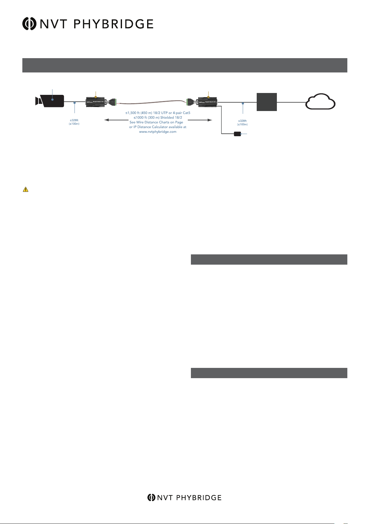
INSTALLATION INSTRUCTIONS
6 Watt IP Camera
NV-EC1701U NV-EC1701U
Complete Installation Guide
Model NV-EC1701U
EoC Ethernet over Coax Transceiver
with PoE, PoE+, or High Power PoE
Ethernet over Coax EoC Transceiver
Cat5
Figure 1 - Typical Installation
Most installations that use the NV-EC1701U transceiver
involve the replacement of old analog equipment with new
IP devices, while reusing the installed wire.
To prevent damage, disconnect all analog equipment
before installing the IP equipment. The NV-EC1701U uses
the wire to deliver 55VDC.
Transceiver Conguration
NV-EC1701U transceivers must be congured to
communicate exclusively with other transceivers within their
Network Group. The conguration process is described on
page 3.
Connecting the Camera End
Install the new IP device. Mount the NV-EC1701U nearby
or within 328 feet (100 meters). Connect an RJ45 cable
between the network connector (PoE) of the IP device and
the RJ45 jack on the NV-EC1701U.
Connect the screw-terminal adaptor to the BNC jack on the
NV- EC1701U and connect one wire conductor to a terminal
marked “+”. Connect the other wire conductor to a terminal
marked “-”. Observe polarity so that it will match that of
the control-room end.
For most installations, the IP device’s power will be low
enough, and the wire distance short enough, so that the IP
device and its NV-EC1701U can receive power through the
wire. In most cases, a power supply will not be needed at
this end. For additional details, see pages 6 & 7.
Set the NV-EC1701 PoE toggle switch (located near the
BNC connector) to ON if the connected IP device requires
PoE to be delivered by the NV-EC1701 and to OFF if PoE
should not be delivered by NV-EC1701. This setting relates
to power delivery at the Ethernet RJ45 connection.
Ethernet over Coax EoC Transceiver
Cat5
9
Ethernet
Switch
55VDC Power Supply
LAN/WAN
This will provide power to the entire system, including the
cameras. The Blue “Power” LEDs will illuminate on both
transceivers.
If the LEDs do not light, check the wire polarity. If the blue
LEDs blink, then the power supply is cycling on and o
due to an overload condition. Check for wire faults or
excessive loading.
Connect an RJ45 patch-cord between the RJ45 jack on
the NV-EC1701U and your ethernet switch.
The Green LEDs will illuminate when a network link is
established, and will blink when data trac is present.
MULTIPLE CAMERAS
The NV-EC1701U transceivers communicate with each
other using a bus-architecture. This means that multiple
remote NV-EC1701Us may be connected together to
an NV-EC1701U at the control-room. The cables are
connected together using the screw-terminal adaptor.
Extra screw terminals are provided to allow easy
connection. Star, daisychain, or any combination of
topologies, including mixing of UTP and coax media may
be used.
Unlike coax-based signal distribution, the high frequency
signals that are transmitted can be susceptible to very
small amounts of crosstalk from other NV-EC1701U
network groups. For this reason, do not transmit signals
from dierent network groups within adjacent wire pairs.
PoE CONSIDERATIONS
The NV-EC1701U transceiver supports full PoE, PoE+,
and High Power cameras, as well as non-powered legacy
devices.
Connecting the Control-room End
Install a second NV-EC1701U at the control-room end of
the wire.
Connect the screw-terminal adaptor to the BNC jack on the
NV-EC1701U and connect one wire conductor to a terminal
marked “+”. Connect the other wire conductor to a terminal
marked “-”. Be sure to match the polarity of the remote-end
NV-EC1701U.
If rack-mounting is desired, use the NV-RMEC16U-90 tray,
which supports up to four NV-EC1701U transceivers.
Connect a class 2 (SELV) 55VDC power supply to the
power jack on the NV-EC1701U.
Page 5 of 14
Unlike conventional PoE, voltage-drop and load current
must be conrmed by the installer. See “High Power
Extended Distance Considerations” on page 6 and use
the IP Distance Calculator at www.nvtphybridge.com.
NVT Phybridge’s Class 2 current limiting ensures safety
of the installation during fault conditions, while delivering
higher power (up to 90 watts) with more ecient allocation
amongst loads. Up to two power supplies may be used
within a network group.
888.901.3633 | +44 (0) 208 977 6614
www.nvtphybridge.com
Copyright © 2017 NVT Phybridge
2017/11

6 Watt IP
Analog Camera
PoE Camera
IP CAMERA & NVR CONSIDERATIONS
Cat5
NV-EC1701U NV-EC1701U
Complete Installation Guide
Model NV-EC1701U
EoC Ethernet over Coax Transceiver
with PoE, PoE+, or High Power PoE
Network
Video
Recorder
Cat5
Ethernet
Switch
55VDC Power Supply
Cat5
Ethernet over Coax EoC Transceiver
Ethernet over Coax EoC Transceiver
Cat5
9
Figure 2 - IP Camera & NVR Installation
TRANSCEIVER-TO-TRANSCEIVER NETWORK ARCHITECTURE
The NV-EC1701U transceivers provide transparent
end-to-end 10-baseT or 100-BaseT connectivity with
auto detection and autocrossover. This means that IP
cameras or other devices may be installed at one end,
and their data is transparently delivered to the other end.
Please read conguration instructions on page 3 before
installing.
Wire distances up to 1,500ft (450m) are supported,
although local power may be required for extended
distances. See page 9.
The NV-EC1701U supports TCP/IP, UDP, HTTP, Multi-
cast, and other standard protocols. This allows for the
transmission of other network trac besides streaming
video.
For IP-based CCTV applications, there are some
network conguartions that are robust, and others that
are not recommended. In general, it is best to deploy
a separate LAN exclusively for video trac.
Although it is possible to place IP cameras onto the enduser’s “Enterprise LAN”, there are several disadvantages
in doing so. These include:
Trac Management Considerations
When sharing the resources of a LAN, the nature of
the trac must be well understood for it to operate
eciently. For most end-users, the business use of
their LAN is constantly changing, critical for their dayto-day operations, and not managed by the same
group that manages their security. IP video can often
consume large amounts of bandwidth, which may or
may not be compatible with existing IT trac.
Security Considerations
Most surveillance systems are installed specically
to protect against breaches in security. A shared LAN
provides potential opportunities for unauthorized
access to security assets. Sning IP addresses can
result in the unintended disclosure of IP cameras or
network vulnerabilities. Spoong IP addresses could
result in the disruption of recording.
LAN/WAN
Firewall
Page 6 of 14
If you must pass IP camera video through
“public” LANs, ensure that video is recorded
prior to leaving the secure LAN. Then encrypt it
by using a Virtual Private Network (VPN) so that
neither the video, nor its addressing is readable
on the LAN. Many low-cost routers support VPNs.
888.901.3633 | +44 (0) 208 977 6614
www.nvtphybridge.com
Copyright © 2017 NVT Phybridge
2017/11

Complete Installation Guide
NV-EC1701U
Model NV-EC1701U
EoC Ethernet over Coax Transceiver
with PoE, PoE+, or High Power PoE
HIGH POWER EXTENDED DISTANCE CONSIDERATIONS
IP Endpoint
Cat5
IP Endpoint
Cat5
Ethernet over Coax EoC Transceiver
NV-EC1701U
Ethernet over Coax EoC Transceiver
55VDC Power Supply
55VDC Power Supply
NV-EC1701U
Ethernet over Coax EoC Transceiver
9
Cat5
Ethernet
Swtich
LAN/WAN
Figure 3 - Alternate Power Supply Location
The NV-EC1701U has a power inlet connector that receives 55 volts from an external Class 2 SELV desk-style power
supply. Power is distributed to:
1) The transceiver’s internal electronics;
2) the RJ45, provided the connected camera or other device provides the appropriate 27K ohm PoE ‘discovery
signature’. 55V power is provided on pins 1&2 and 5&4, while 3&6 and 7&8 are at 0 V. The use of all four wire-
pairs ensures maximum distance, even for high-power loads, such as P/T/Z cameras; and
3) the coax cable, where it is used by the control-room NV-EC1701U.
For fault/safety, never use more than two power supplies within a network.
Page 7 of 14
888.901.3633 | +44 (0) 208 977 6614
www.nvtphybridge.com
Copyright © 2017 NVT Phybridge
2017/11

50 Watt IP Camera
50 W
Cat5
Complete Installation Guide
Model NV-EC1701U
EoC Ethernet over Coax Transceiver
with PoE, PoE+, or High Power PoE
WIRE TYPE AND DISTANCE CP
NV-EC1701
Ethernet over Coax EoC Transceiver
NV-EC1701
Ethernet over Coax EoC Transceiver
13,400 ft
8,300 ft
6,800 ft
Cat5
(4,085 m)
RG-11
RG-6
RG-59/U
14 AWG
18 AWG
20 AWG
(2,500 m)
(2,070 m)
See Wire Distance Chart on page 9
NVR
55VDC
55VDC
55VDC
60W
60W
60W
LAN/WAN
att IP Camera
Cat5
NV-EC1701
Ethernet over Coax EoC Transceiver
55VDC
Power Supply
BNC “T”
55VDC Power Supply
Figure 4 - Alternate Power Supply Location
The NV-EC1701 has a power inlet connector that receives 55 volts from an external Class 2 SELV desk-style power
supply.
Power is distributed to:
1) the transceiver’s internal electronics;
2) the RJ45, provided the connected camera or other device provides the appropriate 27K ohm PoE ‘discovery signature’.
+55V power is provided on pins 1&2 and 5&4, while 3&6 and 7&8 are at 0 V. The use of all four wire-pairs ensures
maximum distance, even for high-power loads, such as P/T/Z cameras.
3) the coax cable, where it is used by the control-room NV-EC1701.
For fault/safety, never use more than two 60 watt power supplies within a network, and never exceed 120
watts, total.
Page 8 of 14
888.901.3633 | +44 (0) 208 977 6614
www.nvtphybridge.com
Copyright © 2017 NVT Phybridge
2017/11

3.0 W
0 W
4.0 W
5.0 W
6.0 W
8.0 W
10 W
12 W
15 W
18 W
20 W
25 W
30 W
40 W
50 W
2.0 W
2.5 W
24
38
23
21
19
16
14
12
11
9
7
6
4
3
28
30 m
40 m
50 m
60 m
80 m
100 m
120 m
150 m
180 m
200 m
250 m
300 m
400 m
500 m
600 m
800 m
1,000 m1,200 m1,500 m1,800 m2,000
m
98 ft
131 ft
164 ft
197 ft
262 ft
328 ft
397 ft
492 ft
590 ft
656 ft
820 ft
984 ft
1,312 ft
1,640 ft
1,968 ft
2,624 ft
3,280 ft
3,936 ft
4,920 ft
5,904 ft
6,560 ft
2,500 m3,000 m4,000 m5,000
m
8,200 ft
9,840 ft
13,120 ft
16,400 ft
1 CPoE Class 1
2
PoE Class 2
3
PoE Class 3
o
PoE Class 4
h P wr
H
igh
h
P
ower
P
Total Wire Resistance
Camera Wattage
NV-EC1701U Power Data Distance
4
4
C
G
1
Data Limited
C
a
t
6
4
P
r
1
8
/
2
o
r
C
a
t
5
4
P
r
C
a
t
6
2
3
A
W
G
1
P
r
C
a
t
5
2
4
A
W
G
1
P
r
Data Limited
Complete Installation Guide
Model NV-EC1701U
EoC Ethernet over Coax Transceiver
with PoE, PoE+, or High Power PoE
WIRE DISTANCE CHARTS
WIRE DISTANCE CAPACITY
The distance capability of wire is dependent on its ability to deliver DC power, and separately, to deliver high-frequency
data signals.
The graph below shows maximum power delivery when using a 55V power supply. If you are not delivering power to
your camera (or other remote device), then this graph does not apply. Figure 5 shows the maximum network data rate.
A Distance Calculator can be found at www.nvtphybridge.com.
PoE devices require a minimum of 43V to operate. With a 55V supply, we have 13V of allowable voltage drop on the
wire.
The voltage will dip in proportion to the remote (camera) load. The graph below shows what distances are supported for
various loads and wire types.
● The voltage will dip in proportion to the remote (camera) load. The graph below shows what distances are
supported for various loads and wire types.
● Start with the Powered Device (camera) wattage at the left. Sometimes PoE devices are listed as to their PoE
Class rather than wattage. If this is the case, use the colored classes instead.
● Now read over to the right until you nd your kind of wire. Then look up (feet) or down (meters) to nd your
maximum wire distance. If your wire is not among the examples, simply measure its total resistance and nd
that value on the right side of the graph. The maximum supported wattage is on the left.
Wire Distance
Figure 5 - Data Distance Chart
Page 9 of 14
888.901.3633 | +44 (0) 208 977 6614
www.nvtphybridge.com
Copyright © 2017 NVT Phybridge
2017/11

Complete Installation Guide
Model NV-EC1701U
EoC Ethernet over Coax Transceiver
with PoE, PoE+, or High Power PoE
TECHNICAL SPECIFICATIONS
Dimensions (LxWxH) 4.10 x 1.65 x 1.57” (102 x 42 x 40mm)
Weight 5.12 oz. (145 g)
RJ45 Ethernet Interface Connectivity: RJ45 auto-crossover
Wire type: CAT5 or better
Distance: Up to 328ft (100m)
Speed: 10/100 Base T, auto-negotiation auto MDI/MDIX cross-over
Latency: 3ms
Data Throughput: 85Mbps ± 10% usable bandwidth per network.
Power Output: For maximum distance, 55VDC appears on all eight RJ45 pins, and are current-protected
and transient-protected.
Coax Building Wiring
Interface
Power Supply The AC/DC Power supply is external and has the following characteristics
Power Consumption ≤ 3W
Operating Temperature -40°F to 104°F (-40°C to +40° C)
Storage Temperature -40°F to 185°F (-40°C to +85° C)
Humidity 20% to 85% non-condensing
Connectivity: UTP, STP, 18/2 or similar cable
Impedance: 25 to 100 Ohm
Distance: See page 9
Topology: Bus architecture supports star, daisy-chain, or any combination. One control-room
NV-EC1701U may support multiple remote NV-EC1701Us
Transmission Technology: IEEE 1901, 128 bit AES encryption
- Input: 120/240VAC, 50/69Hz
- Output: +55VDC
- IEC Class II, isolated only – Efciency VI
Optional NVTPhybridge Power Supplies
- Model NV-PS55-60W (55VDC, 60W)
- Model NV-PS55-110W (55VDC, 110W)
Important Note:
Distance will often be shorter due to power supply
capacity and wire voltage-drop. See Maximum PerCamera Wire Distance Chart on Page 9.
WARNING: For safety, never use more than two
power supplies. Never exceed 120 watts.
Specications subject to change without notice.
Page 10 of 14
888.901.3633 | +44 (0) 208 977 6614
www.nvtphybridge.com
LED STATUS INDICATORS
BNC
On when
Link detected
Flashes with
Data
Power
Flashes when
initializing or
Joining
Power = Blue “Power On”
BNC/2-wire Interface = Green “Link”
RJ45 Interface = Green “Link”
Copyright © 2017 NVT Phybridge
RJ45
On when
connected
Flashes with
Data
2017/11

MODEL NUMBERS
Product
NV-EC1701U Single transceiver only, no power supply
NV-EC1701U Accessories
Complete Installation Guide
Model NV-EC1701U
EoC Ethernet over Coax Transceiver
with PoE, PoE+, or High Power PoE
NV-PS55-60W
NV-PS55-110W
NV-BNCA
NV-BNCT BNC “T” adaptor
NV-EC4BNC 1:4 BNC splitter adaptor
NV-RJ45A RJ45 Screw terminal adaptor
NV-PC4PR
NV-DPSC4
NV-RMEC16U
55VDC power supply, 60 watts with IEC line cord
55VDC power supply, 110 watts with IEC line cord
BNC Screw terminal adaptor
RJ45 Patch Cord, 4-pair 3’ (1m) Grey
Detachable Power Supply Cord Splitter 1:4 2ft
Rack mounting chassis, 19” x 1U
Holds up to 4 NV-EC1701U transceivers plus 60W or 110W power supplies.
Includes NV-DPSC4 Power Cord Splitter (Transceivers and power supplies not
included)
Page 11 of 14
888.901.3633 | +44 (0) 208 977 6614
www.nvtphybridge.com
Copyright © 2017 NVT Phybridge
2017/11

TRANSCEIVER KITS
NV-EC1701U Transceiver Kits
Single 60 Watt Eo2 Transmission System
NV-EC1701U-KIT1:
• 2: NV-EC1701U Transceivers
• 1: NV-PS55-60W Power Supply with IEC line cord
• 2: NV-PC4PR patch-cord
Single 110 Watt Eo2 Transmission System
NV-EC1701U-K1H:
• 2: NV-EC1701U Transceivers
• 1: NV-PS55-110W Power Supply with IEC line cord
• 2: NV-PC4PR patch-cord
Dual 60 Watt Eo2 Transmission System
NV-EC1701U-KIT2:
• 3: NV-EC1701U Transceivers
• 1: NV-PS55-60W Power Supply with IEC line cord
• 3: NV-PC4PR patch-cord
Complete Installation Guide
Model NV-EC1701U
EoC Ethernet over Coax Transceiver
with PoE, PoE+, or High Power PoE
Dual 110 Watt Eo2 Transmission System
NV-EC1701U-K2H:
• 3: NV-EC1701U Transceivers
• 1: NV-PS55-110W Power Supply with IEC line cord
• 3: NV-PC4PR patch-cord
Triple 60 Watt Eo2 Transmission System
NV-EC1701U-KIT3:
• 4: NV-EC1701U Transceivers
• 1: NV-PS55-60W Power Supply with IEC line cord
• 4: NV-PC4PR patch-cord
Dual 110 Watt Eo2 Transmission System
NV-EC1701U-K2H:
• 4: NV-EC1701U Transceivers
• 1: NV-PS55-110W Power Supply with IEC line cord
• 4: NV-PC4PR patch-cord
Quadruple 60 Watt Eo2 Transmission System
NV-EC1701U-KIT4:
• 5: NV-EC1701U Transceivers
• 1: NV-PS55-60W Power Supply with IEC line cord
• 5: NV-PC4PR patch-cord
Quadruple 110 Watt Eo2 Transmission System
NV-EC1701U-K4H:
• 5: NV-EC1701U Transceivers
• 1: NV-PS55-110W Power Supply with IEC line cord
• 5: NV-PC4PR patch-cord
Page 12 of 14
888.901.3633 | +44 (0) 208 977 6614
www.nvtphybridge.com
Copyright © 2017 NVT Phybridge
2017/11

Ethernet Switch
Model NV-EC1701U
EoC Ethernet over Coax Transceiver
with PoE, PoE+, or High Power PoE
MULTICAST PACKET SUPPORT
Complete Installation Guide
IP Camera
NV-EC1701U
Ethernet over Coax EoC Transceiver
2-wire Cable
Cat5
Figure 6 - Multicast Network
On rare occasions, a customer will experience a problem
where a camera sending unicast packets performs
awlessly, but the NV-EC1701Us fail to deliver multicast
streams.
To understand this, we need to delve a little deeper into
how multicast networking works. To do this, we will rst
explore unicast packet transmission.
With unicast packets, there is a source (the camera)
and a destination (the NVR). Packets are generated
by the source and directed to a single destination. The
rst time a packet is sent, the switch has never heard
of the destination address. So it sends a broadcast
transmission to ALL destinations. The correct recipient
acknowledges the packet. The switch snoops in on
that response and memorizes which port is associated
with that transmission. Subsequent transmissions are
directed ONLY to the recipient’s port, thereby reducing
bandwidth on other parts of the network.
NV-EC1701U
Ethernet over Coax EoC Transceiver
Embedded IGMP
Network Querier
Cat5
Ethernet
Switch
Firewall
55VDC Power Supply
Network
Video
Recorder
In practice, a multicast source (camera) sends its data not
to the destination, but to a ctitious “Group IP Address.”
Destination devices (the NVR), in response to an IGMP
querier request, send a request to the IGMP host asking
to be included as a destination for that group.
Switches and routers allow these multicast packets
through so they can be received by those interested
devices (NVR) and block them from being delivered
elsewhere. It would be inappropriate for the switch
to send a multicast stream everywhere, as it would
clog the network.
The NV-EC1701Us are not point-to-point devices. They
join together to function as a switch. Like a switch, they
listen for IGMP reports and block unknown multicast
packets. This is particularly important in a multi-camera
environment, as we do not want the stream from one
camera being delivered to all other cameras. That could
generate too much trac.
LAN/WAN
With multicast packets, the same bandwidth
considerations apply. Switches and routers do not
routinely deliver multicast trac to all destinations.
Instead they rely on a special control protocol to identify
and report which multicast trac should go where.
That protocol is called Internet Group Management
Protocol (IGMP). IGMP is a shared “querier” control
resource that is implemented on a host, such as a switch
or router, within the network. Virtually all routers and
most switches are equipped with an IGMP querier.
That host is responsible for sending IGMP queries to
multicast devices, requesting the generation of an IGMP
Report. That report is monitored by switches and routers
within the network. That monitoring is called IGMP
Snooping. These switches and routers keep a state
table and use it to determine to which ports to deliver
each multicast stream.
Page 13 of 14
888.901.3633 | +44 (0) 208 977 6614
www.nvtphybridge.com
On rare occasions an installation will be created without
the required IGMP querier. If the switches are not
equipped with IGMP snooping then they just deliver all
multicast trac everywhere. If the NV-EC1701Us do not
receive IGMP reports, then they will BLOCK UNKNOWN
MULTICAST PACKETS, and the video will not pass
through.
An investigation can be performed as necessary using a
Packet Snier, such as WireShark.
The bottom line is that an IGMP querier is required for a
properly congured multicast network. Contact NVT for
further information.
Copyright © 2017 NVT Phybridge
2017/11

Complete Installation Guide
Model NV-EC1701U
EoC Ethernet over Coax Transceiver
with PoE, PoE+, or High Power PoE
TROUBLESHOOTING PRODUCT DESCRIPTION
Conrm that the NVTP transceivers have been congured
to communicate with each other, per instructions on
page 3.
If you are experiencing problems, attempt to simplify
your setup. Test each cable segment separately. For
example, test the IP camera directly at the ethernet
switch without other equipment. Then add in the NVTP
transceivers, back-to-back. Test each segment of a long
cable- run independently. Attempt to isolate the problem.
Most IP camera installation problems involve conguring
the IP camera and the recorder to recognize each other.
If in doubt, connect the camera directly to the Ethernet
switch, bypassing the transceivers.
Consult the IP camera and/or recorder installation
manuals for conguration instructions, or contact the
camera or recorder manufacturer.
NETWORK DIAGNOSTIC TOOLS
NVT Phybridge has developed a Console Utility that
can be downloaded from www.nvtphybridge.com. Once
installed on any Windows PC, the application scours
the network for NVTP devices, and reports each of their
MAC addresses, as well as the MAC addresses of any
other NVTP devices within its joined group.
Additional network tools, such as Packet Sniers or
Trac generators are available from other sources such
as LAN Shark, LANTrac, etc.
The NVT Phybridge Model NV-EC1701U Ethernet over
2-wire Transceiver is a compact media converter that
allows 10/100 BaseT Ethernet and PoE, PoE+, or high-
power PoE to be transmitted using 2-wire cable. These
devices are typically used in legacy installations where
existing cable is redeployed as part of an upgrade to
IP cameras. 48-55VDC class 2 power is delivered to
one transceiver, which distributes it to multiple remote
transceivers, and their PoE cameras (or other IP
devices).
These transceivers are extremely simple to use, with no
IP or MAC address conguration required. Status LEDs
indicate power and link connectivity/activity for RJ45 and
BNC ports.
COMPLIANCE AND AGENCY APPROVALS
All the compliance information is available on our website
www.nvtphybridge.com.
WARRANTY
The NV-EC1701U is backed by NVT Phybridge’s award
winning customer support and limited lifetime warranty.
CUSTOMER SUPPORT
NVT Phybridge customer support is available for
consultation from 6:00AM - 7:00PM EST Monday
through Friday. In addition, emergency after hours
callback support is available.
Corporate Headquarters: +1 (888) 901-3633
Corporate Headquarters Fax : +1 (866) 252-9148
UK European Headquarters: (+44) (0)20 8977 6614
Email Headquarters: insidesales@nvtphybridge.com
Email UK European Headquarters: eusales@nvtphybridge.com
Web Home Page: www.nvtphybridge.com
PRODUCT RETURNS
Please call before returning units to NVT Phybridge.
Returned materials must have a “Returned Materials
Authorization” (RMA) number from NVT Phybrigde
marked on the outside of the shipping carton.
Page 14 of 14
888.901.3633 | +44 (0) 208 977 6614
www.nvtphybridge.com
Copyright © 2017 NVT Phybridge
2017/11
 Loading...