

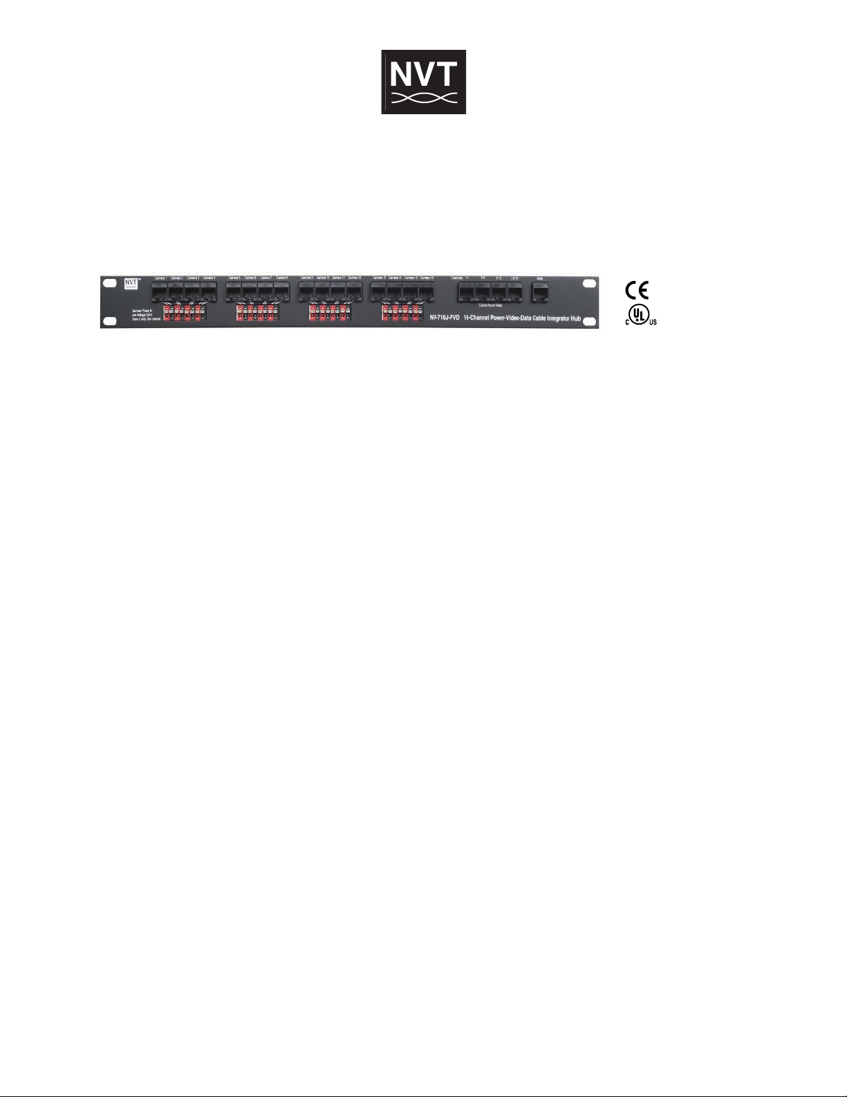
Model NV-716J-PVD
Cable Integrator Hub
Features:
• Connectivity for up to sixteen cameras, each via a single RJ45 4-pair cable
• Use with the NV-216A-PV or NV-218A-PVD transceivers or the NV-226J-PV transmitter at the camera
• Uses any third-party power supply to power cameras via UTP over significant
distances (see Power Distance Chart)
• Cable-management solution from the camera to the Wiring Closet and on to
the Control Room
• 1U high; 1" deep; wall or rack-mountable
• Limited lifetime warranty
Typically installed in the wiring closet or IDF room, the NV-716J-PVD is a passive “pass-through” wiring device that efficiently consolidates camera power, video, and pan/tilt/zoom telemetry data onto a minimum of 4-pair RJ45 cables.
Power, video and data are converted at the camera using a PVDTMtransceiver which utilizes a single 4-pair cable with RJ45
connectors to deliver each camera’s signals to the NV-716J-PVD. Up to sixteen cameras are supported. The NV-716J-PVD
receives low-voltage camera power from any third-party multi-output Class 2 power supply. Control Room connections are
achieved with a single 4-pair RJ45 cable for each group of four cameras. P/T/Z telemetry data, if required, passes through
another 4-pair RJ45 cable. Control Room connections may be made using any multi-channel NVT receiver or hub. All equipment employs industry-standard EIA/TIA 568B pinouts.
Network Video Technologies
4005 Bohannon Drive • Menlo Park, CA 94025 • USA
(+1) 650.462.8100 • FAX (+1) 650.326.1940
nvt.com • www.nvt.com/email
-13-
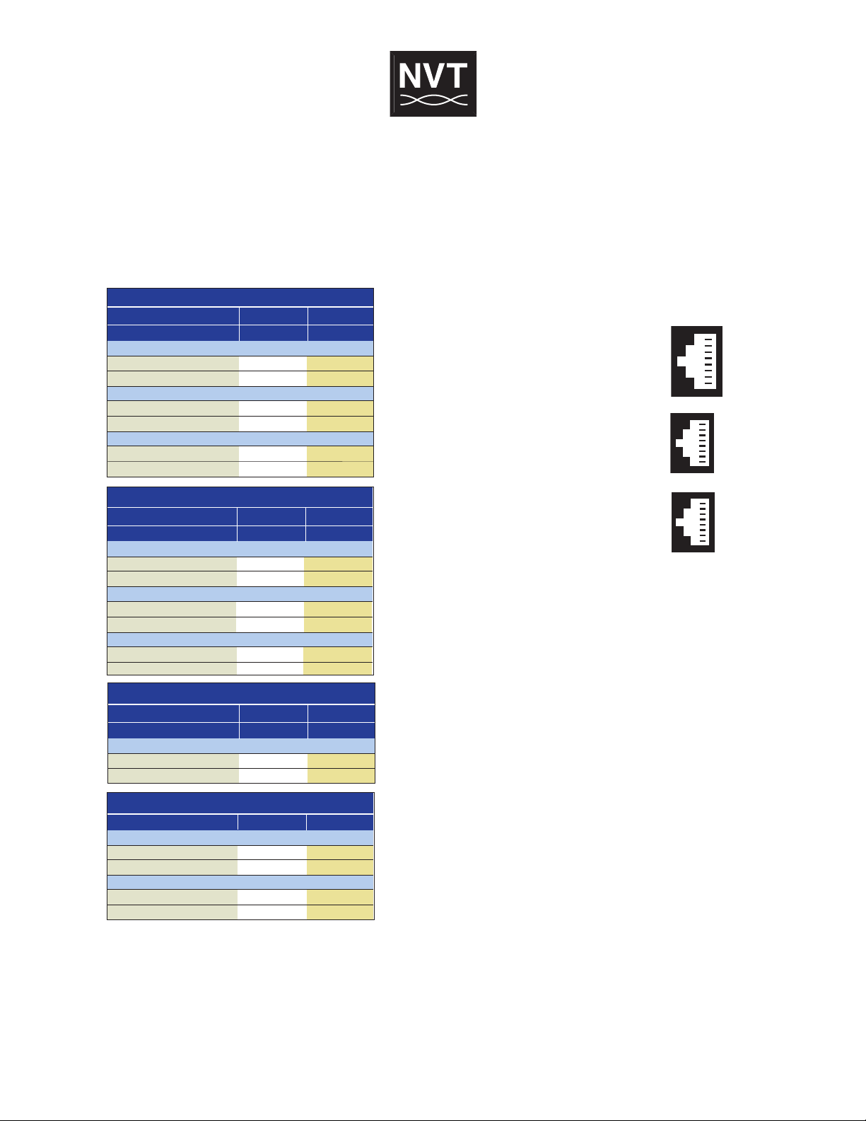
1
2
3
4
5
6
7
8
Video +
Video
Data +
Power
Power +
Data
Power +
Power
-
1
2
3
4
5
6
7
8
V
ideo 2 +
V
ideo 2
-
V
ideo 3 +
V
ideo 1
-
V
ideo 1 +
V
ideo 3
-
V
ideo 4 +
V
ideo 4
-
1
2
3
4
5
6
7
8
D
ata B +
D
ata B
-
D
ata C +
D
ata A
-
D
ata A +
D
ata C
-
D
ata D +
D
ata D
-
Model NV-716J-PVD
Fixed 12VDC Camera used with NV-226J-PV
Power Supply Voltage
1,586ft (482m)
1,999ft (609m)
795ft (242m)
1,002ft (306m)
2,220ft (677m)
2,799ft (853m)
1,113ft (339m)
1,403ft (428m)
B&W Camera, 2.4 W
2-pair 24 AWG
2-pair 23 AWG
Color Camera 4.8 W
2-pair 24 AWG
2-pair 23 AWG
24 VAC
28 VAC
P/T/Z 24VAC Camera
Power Supply Voltage
Minimum Voltage at Camera
90ft (27m)
113ft (35m)
210ft (64m)
265ft (81m)
NV-218A-PVD
P/T/Z Camera 1,000 mA, 21 W
2-pair 24 AWG
2-pair 23 AWG
24 VAC
21 VAC
28 VAC
21 VAC
Fixed Camera 24VAC only, used with NV-216A-PV
P
ower Supply Voltage
Minimum Voltage at Camera
789ft (240m)
994ft (303m)
393ft (120m)
495ft (151m)
262ft (80m)
331ft (101m)
1,840ft (561m)
2,320ft (707m)
916ft (279m)
1,155ft (352m)
612ft (186m)
771ft (235m)
B&W Camera, 2.4 W
2-pair 24 AWG
2-pair 23 AWG
Color Camera, 4.8 W
2-pair 24 AWG
2-pair 23 AWG
Color Camera, 7.2 W
2-pair 24 AWG
2-pair 23 AWG
2
4 VAC
21 VAC
28 VAC
2
1 VAC
Fixed Dual Voltage 24VAC12/VDC Camera with NV-2 16A-PV
Power Supply Voltage
Minimum Voltage at Camera
1,753ft (534m)
2,210ft (674m)
874ft (266m)
1,102ft (336m)
583ft (173m)
735ft (224m)
2,454ft (748m)
3,000ft (915m)
1,223ft (373m)
1,542ft (470m)
815ft (250m)
1,025ft (310m)
B&W Camera 100 mA, 2.4 W
2-pair 24 AWG
2-pair 23 AWG
Color Camera 200 mA, 4.8 W
2-pair 24 AWG
2-pair 23 AWG
Color Camera 300 mA, 7.2 W
2-pair 24 AWG
2-pair 23 AWG
24 VAC
14 VAC
28 VAC
14 VAC
Cable Integrator
Technical Specifications
W I R E D I S T A N C E (Power Distance Charts)
Supply voltage, wire resistance and minimum camera operating
voltage determine the maximum camera distance. Examples
assume a minimum 21 VAC at the 24 VAC camera:
V I D E O
UTP, RJ45 Connectors 100 ohms
P O W E R
16 to 24AWG (0,5mm to 1,3mm)
C A M E R A P V D C O N N E C T I O N S
Four front-panel RJ45 outputs support up to four fixed
or P/T/Z telemetry cameras over 4-pair UTP.
C O N T R O L R O O M V I D E O
UTP video signals are passed through the unit and
delivered to the control/MDF room via rear-panel
RJ45 connectors.
C O N T R O L R O O M DA T A
RS-422 or RS-485 type P/T/Z telemetry/ data signals are
paralleled together in groups of four, and passed through
the unit and delivered to the control room via a rear-panel
RJ45 connector.
C O N T R O L
UTP, RJ45 Connectors 100 ohms
Notes: Actual distance will depend on the camera’s inrush and operating current, minimum
operating voltage, and the wire’s environmental temperature. Please consult NVT Customer
Support for further information.
Wire should be category rated Unshielded Twisted-Pair (UTP) cable, Low voltage camera power,
video, and RS-422 or RS-485 telemetry may be sent within the same wire bundle. Do not run
24VAC or 28VAC in the same wire bundle with analog telecom signals. However you may share
the same wire/cable tray.
An online wire Power Distance Calcula tor is available at www.nvt.com under Product Support.
E N V I R O N M E N T A L
Temperature -22 to +167 °F (-30 °C to +75 °C)
Humidity (non-condensing) 0 to 95%
M E C H A N I C A L
Dimensions, excluding brackets and connectors
19in wide x 1.73in high x .8in deep
(482mm wide x 44mm high x 21mm deep)
Weight 0.94lb (0.43kg)
Mounting Rack mount
Specifications subject to change without notice.
-14-
 Loading...