

NVT NV-214A-M User manual
NV-214A-M
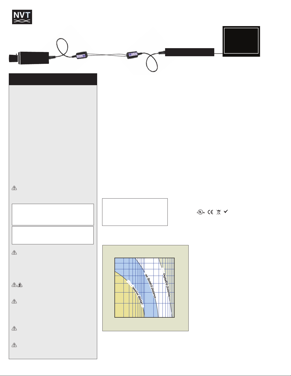
Monitor
DVR
NV-214A-M
Analog
Camera
NV-214-A-M Product Installation Manual
RoHS
235
315
400
475
550
630
700
780
3 MHz
4 MHz
5 MHz
6 MHz
9 MHz
8 MHz
7 MHz
10 MHz
100ft
300ft
1,000ft
1 mile
3,000ft
10,000ft
30m
100m
300m
1,6km
1km
3km
M
a
x
P
a
s
s
i
v
e
D
i
s
t
a
n
c
e
M
a
x
S
t
u
b
E
Q
D
i
s
t
a
n
c
e
M
a
x
D
i
g
i
t
a
l
E
Q
D
i
s
t
a
n
c
e
IMPORTANT SAFETY INSTRUCTIONS
1) Read these instructions.
2) Keep these instructions.
3) Heed all warnings.
4) Follow all instructions.
5) Do not use this apparatus near water.
6) Clean only with a dry cloth.
7) Install in accordance with the manufacturer’s
instructions.
8) Only use attachments/accessories specified by the
manufacturer.
9) Refer all servicing to qualified service personnel.
Servicing is required when the apparatus has
been damaged in any way, such as a power
supply cord or plug is damaged, liquid has been
spilled, or objects have fallen into the apparatus,
the apparatus has been exposed to rain or
moisture, does not operate normally, or has been
dropped.
This installation should be made by a qualified
service person and should conform to all local
codes.
TO REDUCE THE RISK OF ELECTRICAL SHOCK,
DO NOT REMOVE COVER OR BACK. NO USER
SERVICEABLE PARTS INSIDE. REFER SERVICING
TO QUALIFIED SERVICE PERSONNEL.
WARNING: TO REDUCE THE RISK OF ELECTRI
CAL SHOCK, DO NOT EXPOSE THIS APPARATUS
TO RAIN OR MOISTURE.
WARNING Do not install the unit in an environ
ment where the operating ambient temperature ex
ceeds 122°F (50° C). No naked flame sources, such
as lighted candles should be placed on the
apparatus.
WARNING Do not interconnect multiple
outputs.
to dripping or splashing and no objects filled with
liquids, such as vases, shall be placed on the
apparatus.
in the same conduit as highvoltage wiring.
WARNING The apparatus shall not be exposed
WARNING For safety, never put NVT signals
WARNING Do not restrict airflow around any
active powered NVT products.
Wiring Tech Notes
1. Use point-to-point Unshielded Twisted Pair wire, 24-16 AWG
(0,5-1,5mm), stranded or solid, Category rated wire.
2. The video signal may co-exist in the same wire bundle as
other video, telephone, data, control signals, or low-voltage
power. It is also OK to run NVT video signals in or near electromagnetic fields (in accordance with National Electrical
Code, local, or other local safety requirements).
3. Measure the wire distance.
4. DO NOT USE individually shielded twisted pair. Overall
shielded, multi-pair (6pr +) or foiled Cat5 is OK.
5. DO NOT USE UN-TWISTED WIRE.
6. Due to near-end crosstalk, don’t send a transmit and a receive
signal in the same wire bundle over 1000ft (300m). Exceptions:
Category 5 or better cable, up to 2,000 ft (600m) are OK.
7. Passive NVT NV-214A-M will transmit receive “up the coax”
P/T/Z control signals up to 750ft (225m)
8. Unless prohibited by Electrical Code, the camera and NVT
should float, relative to earth ground. This will reduce sensitivity to lightning strikes.
Measure Your Wire Distance
Note: All NVT quoted distance specifications include any coax in
the run. It is recommended that the wire distance be measured
to ensure that the capability of the NVT product is correct.
Wire resistance may be measured with an ohm-meter by
shorting the two conductors together at the far end, and measuring the loop-resistance out and back.
Wire Resistance per 1,000ft (300m)
24 AWG (0,53 mm) = 52 ohms
23 AWG (0,57 mm) = 42 ohms
22 AWG (0,64 mm) = 33 ohms
20 AWG (0,81 mm) = 21 ohms
19 AWG (0,91 mm) = 16 ohms
18 AWG (1,02 mm) = 13 ohms
Use the correct receiver for your wire distance. If your distance
does not exceed the maximum passive distance, use a second
NV-214A-M at the monitor end. Otherwise, visit nvt.com to
select the appropriate active receiver.
on
uti
esol
R
nes of
era Li
am
C
Connecting the Camera End
1. Connect the baseband video signal from the camera to
the NV-214A-M.
2. Connect the UTP output of the NV-214A-M to existing or new
unshielded twisted pair wiring by attaching each conductor of
a twisted pair of wires to each screwless terminal. Note wire
colors so that polarity may be observed at the receiving end.
Connecting the Monitor End
1. Connect the UTP conductors to the screwless terminals of the
NV-214A-M. Observe polarity.
2. Connect the NV-214A-M to the DVR, video monitor, or other
video equipment.
3. Confirm that your monitor or other receiving equipment is
correctly terminated with a single 75W terminator.
Troubleshooting
If you are experiencing problems, attempt to simplify your setup.
Test each cable segment separately. For example, test the camera and monitor together without the other equipment. Then add
in the NVT transceivers, back-to-back. Test each segment of a
long cable-run independently. Attempt to isolate the problem.
Customer Support
NVT customer support is available for consultation from 8:00 AM
to 5:30 PM PST Monday through Friday. In addition, emergency
after-hours callback support is available.
US Office:(+1) (650) 462-8100 Fax:(+1) (650) 326-1940
Email USA: www.nvt.com/email Web: www.nvt.com
UK Office:(+44) (0)20 8977 6614 Fax:(+44) (0)20 8973 1855
Email UK: www.nvt.com/email Web: www.nvt.com
Returns
Please call before returning units to NVT. Returned materials must
have a “Returned Materials Authorization” (RMA) number from
NVT marked on the outside of the shipping carton.
Agency
These NVT products are listed and/or conform to the following
certifications and directives.
UL Listed to UL2044 or UL/IEC 60065.
cUL Listed to CAN/CSA22.2 No. 1 for Canada.
CE Mark under EMC and low voltage Directives for the European
Union. Complies with FCC part 15B limits
Limited Warranty
NVT warrants that the product conforms to NVT’s applicable published specifications and is free of defects and workmanship, for
the life of the product.
There shall be no other warranties, express, statutory or oth-
erwise, including any implied warranty of merchantability of fitness or any other obligation on the part of NVT with respect to any
of the products.
In the event that any product is damaged or altered or modi-
fied without the express written consent of NVT, any warranty for
y
those products will cease and NVT will have no further liability
nc
as it pertains to those products. NVT assumes no responsibility
que
for damages or penalties incurred resulting from the use of this
re
F
product in a manner or location other than for which it is intended.
NVT’s liability under any warranties shall be discharged by
replacing or repairing any part or parts which do not conform to
the applicable warranty under normal and proper use. NVT’s
liability with respect to any product shall not exceed a refund of
the price received by NVT for that product, and in no event shall
NVT have any liability for any incidental, consequential, special,
or indirect damages.
Some states do not allow the exclusion or limitation of special,
incidental or consequential damages, so the above limitation or
exclusion may not apply to you. This warranty gives you specific
legal rights, and you may also have other rights which vary from
state to state.
Specifications subject to change without notice.
Copyright © 2012 NVT, Inc. 451-214-1-A 08/12
 Loading...