

Page 1

Release Note
This document has been modified from the original Nvidia Media Shield User’s Guide.
Some of the Nvidia screen captures may be different than your system.
Please Note: In order to access the RAID utility, press F10 repeatedly once the boot
screen appears.
Press Ctrl-X to exit the RAID utility, it will automatically save any changes.
There is not an option to exit without saving changes.
Windows Vista sees the RAID as a single logical drive, but it does not “color code” it as
a RAID storage solution in Administrative Tools. The RAID logical drive is color coded
the same as a single physical drive.
The RAID utility does not auto-rebuild a defective or replacement RAID HDD. The
rebuild process must be initiated in the RAID utility. The rebuild process may take
several hours depending on the size of the drives.
Here are some additional RAID definitions that may prove useful when configuring the
RAID array.
Striping = RAID 0
Mirroring = RAID 1
Stripe Mirroring = RAID 0+1
RAID 5 = RAID 5
Spanning = JBOD
Page 2

TABLE OF CONTENTS
1.About NVIDIA RAID . . . . . . . . . . . . . . . . . . . . . . . . . . . . . . . . . . . . . . . . . . . . . . . . . 3
RAID Arrays . . . . . . . . . . . . . . . . . . . . . . . . . . . . . . . . . . . . . . . . . . . . . . . . . . . . 3
RAID 0 . . . . . . . . . . . . . . . . . . . . . . . . . . . . . . . . . . . . . . . . . . . . . . . . . . . . . . . . .4
RAID 1 . . . . . . . . . . . . . . . . . . . . . . . . . . . . . . . . . . . . . . . . . . . . . . . . . . . . . . . . .5
RAID 0+1. . . . . . . . . . . . . . . . . . . . . . . . . . . . . . . . . . . . . . . . . . . . . . . . . . . . . . . 6
RAID 5 . . . . . . . . . . . . . . . . . . . . . . . . . . . . . . . . . . . . . . . . . . . . . . . . . . . . . . . . .7
JBOD . . . . . . . . . . . . . . . . . . . . . . . . . . . . . . . . . . . . . . . . . . . . . . . . . . . . . . . . .8
2.Setting Up Your RAID Configuration . . . . . . . . . . . . . . . . . . . . . . . . . . . . . . . . . . . . . .11
Setting Up a Non-Bootable RAID Array . . . . . . . . . . . . . . . . . . . . . . . . . . . . . . .11
Setting Up the BIOS . . . . . . . . . . . . . . . . . . . . . . . . . . . . . . . . . . . . . . . . . . . . . . .11
Setting Up a Bootable RAID Array . .. . . . . . . . . . . . . . . . . . . . . . . . . . . . . . . . . 15
Configuring the NVIDIA RAID BIOS . . . . . . . . . . . . . . . . . . . . . . . . . . . . . . . . .18
3.Rebuilding Your Mirrored RAID . . . . . . . . . . . . . . . . . . . . . . . . . . . . . . . . . . . . . . . . .23
Note pages 9,10, and 14 were removed from this document.
Page 3

NVIDIA Applications MediaShield User’s Guide Version 3.1
Published by
NVIDIA Corporation
2701 San Tomas Expressway
Santa Clara, CA 95050
Notice
ALL NVIDIA DESIGN SPECIFICATIONS, REFERENCE BOARDS, FILES, DRAWINGS, DIAGNOSTICS,
LISTS, AND OTHER DOCUMENTS (TOGETHER AND SEPARATELY, “MATERIALS”) ARE BEING
PROVIDED “AS IS.” NVIDIA MAKES NO WARRANTIES, EXPRESSED, IMPLIED, STATUTORY, OR
OTHERWISE WITH RESPECT TO THE MATERIALS, AND EXPRESSLY DISCLAIMS ALL IMPLIED
WARRANTIES OF NONINFRINGEMENT, MERCHANTABILITY, AND FITNESS FOR A PARTICULAR
PURPOSE.
Information furnished is believed to be accurate and reliable. However, NVIDIA Corporation assumes no
responsibility for the consequences of use of such information or for any infringement of patents or other rights of
third parties that may result from its use. No license is granted by implication or otherwise under any patent or patent
rights of NVIDIA Corporation. Specifications mentioned in this publication are subject to change without notice.
This publication supersedes and replaces all information previously supplied. NVIDIA Corporation products are not
authorized for use as critical components in life support devices or systems without express written approval of
NVIDIA Corporation.
Trademarks
NVIDIA, the NVIDIA logo, MediaShield, 3DFX, 3DFX INTERACTIVE, the 3dfx Logo, STB, STB Systems and
Design, the STB Logo, the StarBox Logo, NVIDIA nForce, GeForce, NVIDIA Quadro, NVDVD, NVIDIA Personal
Cinema, NVIDIA Soundstorm, Vanta, TNT2, TNT, RIVA, RIVA TNT, VOODOO, VOODOO GRAPHICS,
WAVEBAY, Accuview Antialiasing, the Audio & Nth Superscript Design Logo, CineFX, the Communications & Nth
Superscript Design Logo, Detonator, Digital Vibrance Control, DualNet, FlowFX, ForceWare, GIGADUDE, Glide,
GOFORCE, the Graphics & Nth Superscript Design Logo, Intellisample, M-BUFFER, nfiniteFX, NV, NVChess,
nView, NVKeystone, NVOptimizer, NVPinball, NVRotate, NVSensor, NVSync, the Platform & Nth Superscript
Design Logo, PowerMizer, Quincunx Antialiasing, Sceneshare, See What You've Been Missing, StreamThru,
SuperStability, T-BUFFER, The Way It's Meant to be Played Logo, TwinBank, TwinView and the Video & Nth
Superscript Design Logo are registered trademarks or trademarks of NVIDIA Corporation in the United States and/or
other countries. Other company and product names may be trademarks or registered trademarks of the respective
owners with which they are associated.
Intel, Indeo, and Pentium are registered trademarks of Intel Corporation. Microsoft, Windows, Windows NT,
Direct3D, DirectDraw, and DirectX are trademarks or registered trademarks of Microsoft Corporation. OpenGL is a
registered trademark of Silicon Graphics Inc.
Other company and product names may be trademarks or registered trademarks of the respective owners with which
they are associated.
Copyright
© 2004–2005 by NVIDIA Corporation. All rights reserved.
Page 4

C HAPTER
A
BOUT
NVIDIA brings Redundant Array of Independent Disks (RAID) technology—which is
used by the world’s leading businesses—to the common PC desktop. This technology
uses multiple drives to either increase total disk space or to offer data protection.
RAID techniques were first published in 1988 by a multivendor consortium—the RAID
Advisory Board. RAID techniques were divided into different categories or levels.
Originally, RAID levels focused on improving resiliency or data availability. As
additional RAID levels were defined, one was introduced for improving performance. For
all levels, RAID techniques optimize storage solutions by using multiple disks grouped
together and treating them as a single storage resource.
This chapter describes NVIDIA RAID in the following sections:
NVIDIA RAID
• “System Requirements” on page 2.
• “RAID Arrays” on page 3 describes the RAID levels supported by NVIDIA RAID.
• “NVIDIA RAID Features” on page 9 describes additional features offered by NVIDIA
RAID.
NVIDIA Corporation 1
Page 5

RAID Arrays
This section describes the following types of RAID arrays that MediaShield supports:
• RAID 0
• RAID 1
• RAID 0+1
C
About NVIDIA RAID
HAPTER 1
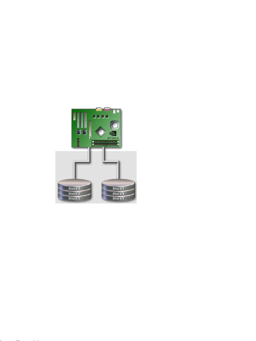
RAID 0 defines a disk striping scheme that improves the disk read and write times for
many applications.
RAID 1 defines techniques for mirroring data.
RAID 0+1 combines the techniques used in RAID 0 and RAID 1 arrays.
• RAID 5
1
RAID 5 provides fault tolerance and better utilization of disk capacity.
• JBOD
JBOD provides a method for combining drives of different sizes into one large disk.
Note: Not all nForce platforms provide support for all the RAID levels listed.
1. RAID 5 is supported on select boards only. Please check with your motherboard manufacturer to determine whether RAID 5 is supported for the type and model of your motherboard.
NVIDIA Corporation 3
Page 6
HAPTER 1
C
About NVIDIA RAID
RAID 0
How RAID 0 Works
In a RAID 0 array, the controller ʺstripesʺ data across multiple drives in the RAID
subsystem. RAID 0 breaks up a large file into smaller blocks and then performs disk reads
and writes across multiple drives in parallel. The size of each block is determined by the
stripe size parameter, which you set during the creation of the RAID 0 set. Performance of
applications running with a RAID 0 can vary greatly depending on the stripe size
configured when creating the array. The default stripe size is 64K, but 32K or 16K may be
more efficient if the application issues many smaller I/O operations. Some amount of trial
and error may be appropriate to find the optimum stripe size.
Figure 1.1
RAID 0 is ideal for applications that require high bandwidth but do not require fault
tolerance. RAID 0 has the best performance and capacity of any RAID level, but the lowest
availability (no fault tolerance). If one drive fails, the entire array fails because part of the
data is missing with no way to recover it other than restoring from a backup.
RAID 0 Array Diagram
Summary of Features and Benefits
• Benefits: Provides increased data throughput, especially for large files.
• Drawbacks: No fault tolerance—all data is lost if any drive in the array fails.
• Uses: Intended for non-critical data requiring high data throughput, or any
environment that does not require fault tolerance.
• Drives: Minimum: 1. Maximum: Up to 8, depending on the platform.
• Fault Tolerance: No.
4 MediaShield User’s Guide – Version 3.1
Page 7
RAID 1
How RAID 1 Works
C
About NVIDIA RAID
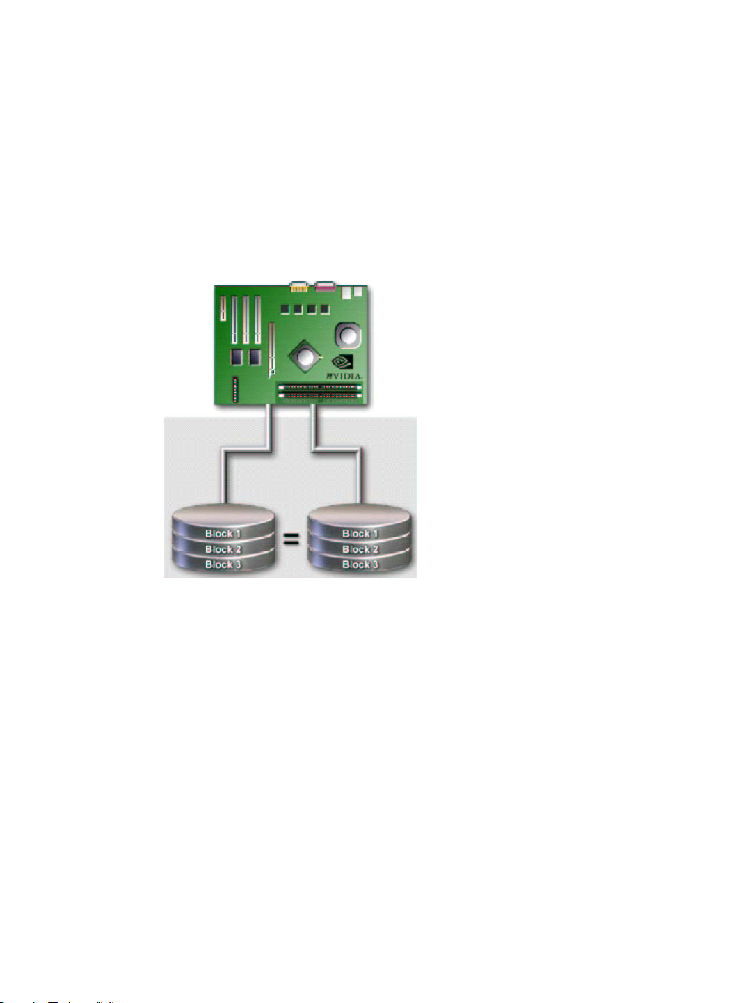
In a RAID 1 array, every read and write is carried out in parallel across two disk drives.
The mirrored—or backup—copy of the data can reside on the same disk or on a second
redundant drive in the array. RAID 1 provides a hot-standby copy of data if the active
volume or drive is corrupted or becomes unavailable due to a hardware failure. RAID 1
techniques can be applied for high-availability solutions, or as a form of automatic backup
that eliminates tedious manual backups to more expensive and less reliable media.
HAPTER 1
Figure 1.2
RAID 1 provides complete data redundancy, but at the cost of doubling the required data
storage capacity, resulting in 50% capacity utilization. Performance is roughly the same as
for a single drive, although in some instances the dual write may be somewhat slower.
RAID 1 Array Diagram
Summary of Features and Benefits
• Benefits: Provides 100% data redundancy. Should one drive fail, the controller
switches to the other drive.
• Drawbacks: Requires two drives for the storage space of one drive. Performance is
impaired during drive rebuilds.
• Uses: RAID 1 is ideal for small databases or any other application that requires fault
tolerance and minimal capacity.
• Drives: Minimum, 2. Maximum, 2.
• Fault Tolerance: Yes
NVIDIA Corporation 5
Page 8

HAPTER 1
C
About NVIDIA RAID
RAID 0+1
How RAID 0+1 Works
RAID 0 drives can be mirrored using RAID 1 techniques, resulting in a RAID 0+1 solution
for improved performance plus resiliency.
Figure 1.3
The controller combines the performance of data striping (RAID 0) and the fault tolerance
of disk mirroring (RAID 1). Data is striped across multiple drives and duplicated on
another set of drives.
RAID 0+1 Array Diagram
Summary of Features and Benefits
• Benefits: Optimizes for both fault tolerance and performance, allowing for automatic
redundancy. May be simultaneously used with other RAID levels in an array, and
allows for spare disks.
• Drawbacks: Requires twice the available disk space for data redundancy, the same as
RAID level 1.
• Drives: Minimum: 4. Maximum: 6 or 8, depending on the platform.
• Fault Tolerance: Yes
6 MediaShield User’s Guide – Version 3.1
Page 9

RAID 5
How RAID 5 Works
C
About NVIDIA RAID
RAID 5 stripes both data and parity information across three or more drives. It writes data
and parity blocks across all the drives in the array. Fault tolerance is maintained by
ensuring that the parity information for any given block of data is placed on a different
drive from those used to store the data itself.
HAPTER 1
Figure 1.4
RAID 5 Array Diagram
Summary of Features and Benefits
• Benefits: An ideal combination of good performance, good fault tolerance, and high
capacity and storage efficiency.
• Drawbacks: Individual block data transfer rate same as a single disk. Write
performance can be CPU intensive.
• Uses: RAID 5 is recommended for transaction processing and general purpose service.
• Drives: Minimum, 3
• Fault Tolerance: Yes
NVIDIA Corporation 7
Page 10

HAPTER 1
C
About NVIDIA RAID
JBOD
How JBOD Works
JBOD stands for “Just a Bunch of Disks”. Each drive is accessed as if it were on a standard
SCSI host bus adapter. This is useful when a single drive configuration is needed, but it
offers no speed improvement or fault tolerance.
Figure 1.5
JBOD Array Diagram
Summary of Features and Benefits
• Benefits: JBOD provides the ability to combine odd size drives using all of the capacity
of the drives.
• Drawbacks: No additional fault tolerance or performance relative to individual disks.
• Uses: JBOD works best if you have odd sized drives and you want to combine them to
make one big drive.
• Fault Tolerance: No
8 MediaShield User’s Guide – Version 3.1
Page 11

S
ETTING
This chapter provides instructions for:
• Setting Up a Non-Bootable RAID Array
• Setting Up a Bootable RAID Array
UP Y
OUR
RAID C
Setting Up a Non-Bootable RAID Array
C HAPTER
ONFIGURATION
RAID arrays can be created/deleted using both MediaShield RAID BIOS and the
MediaShield RAID Manager from Windows. This section only covers basic BIOS setup
required for non-bootable array. See the section ʺSetting Up a Bootable RAID Array” for
instructions on configuring the RAID array in BIOS. See sections on using the
MediaShield RAID Manager for details on configuring non-bootable RAID from
Windows.
Setting Up the BIOS
1 Start your computer, then press Delete to enter the BIOS setup.
NVIDIA Corporation 11
Page 12

HAPTER 2
C
Setting Up Your RAID Configuration
The BIOS CMOS Setup Utility window appears.
Phoenix - Award BIOS CMOS Setup Utility
Standard CMOS Features
Advanced BIOS Features
Advanced Chipset Features
Integrated Peripherals
Power Management Setup
PnP / PCI Configurations
Esc : Quit
F10 : Save & Exit Setup
Figure 2.1
BIOS CMOS Setup Utility Main Window
Onboard IO, IRQ, DMA Assignment ...
Load Fail-Safe Defaults
Load Optimized Defaults
Set Supervisor Password
Set User Password
Save & Exit Setup
Exit Without Saving
: Select Item
^
2 Use the arrow keys to select Integrated Peripherals (see Figure 2.1), then press Enter.
The Integrated Peripherals window appears.
Phoenix - Award BIOS CMOS Setup Utility
Integrated Peripherals
RAID Config
OnChip IDE Channel0
Primary Master PIO
Primary Slave PIO
Primary Master UDMA
Primary Slave UDMA
OnChip IDE Channel1
Secondary Master PIO
Secondary Slave PIO
Secondary Master UDMA
Secondary Slave UDMA
IDE Prefetch Mode
Init Display First
OnChip USB
USB Keyboard Support
USB Mouse Support
Serial - ATA
SATA Spread Spectrum
AC97 Audio
[Press Enter]
[Enabled]
[Auto]
[Auto]
[Auto]
[Auto]
[Enabled]
[Auto]
[Auto]
[Auto]
[Auto]
[Enabled]
[PCI Slot]
[V1.1 - V2.0]
[Disabled]
[Disabled]
[Enabled]
[Disabled]
[Auto]
Item Help
Menu Level
:Move Enter:Select +/-/PU/PD:Value F10:Save ESC:Exit F1:General Help
F5: Previous Values F6: Fail-Safe Defaults F7: Optimized Defaults
Figure 2.2
Integrated Peripherals Window
3 Use the arrow keys to select the RAID Config (see Figure 2.2), then press Enter.
12 MediaShield User’s Guide – Version 3.1
Page 13

The RAID Config window appears.
Phoenix - Award BIOS CMOS Setup Utility
RAID Config
C
Setting Up Your RAID Configuration
HAPTER 2
RAID Enable
SATA 1 Primary
SATA 1 Secondary
SATA 2 Primary
SATA 2 Secondary
:Move Enter:Select +/-/PU/PD:Value F10:Save ESC:Exit F1:General Help
F5: Previous Values F6: Fail-Safe Defaults F7: Optimized Defaults
Figure 2.3
RAID Config Window
[Enable]
RAID [Enabled]
RAID [Enabled]
RAID [Enabled]
RAID [Disabled]
Item Help
Menu Level
4 From the RAID Config window, globally enable RAID, then enable the SATA ports
with disks that you want to use for RAID.
If RAID is enabled globally but not enabled on the individual SATA port, disks on that
port can only be used for non-RAID applications.
In the example in Figure 2.3, three SATA ports are enabled, so the non-bootable RAID
array can include up to 3 SATA disks. If there is a disk Connected to ʺSATA 2
Secondaryʺ, it can not be used for RAID.
5 Press F10 to save the configuration and exit.
The PC reboots.
NVIDIA Corporation 13
Page 14

Setting Up a Bootable RAID Array
This section explains how to configure a bootable NVIDIA RAID array.
Setting Up the BIOS
1 Start your computer, then press Delete to enter the BIOS setup.
The BIOS CMOS Setup Utility screen appears.
Phoenix - Award BIOS CMOS Setup Utility
C
Setting Up Your RAID Configuration
HAPTER 2
Standard CMOS Features
Advanced BIOS Features
Advanced Chipset Features
Integrated Peripherals
Power Management Setup
PnP / PCI Configurations
Esc : Quit
F10 : Save & Exit Setup
Figure 2.5
BIOS CMOS Setup Utility Main Screen
Onboard IO, IRQ, DMA Assignment ...
Load Fail-Safe Defaults
Load Optimized Defaults
Set Supervisor Password
Set User Password
Save & Exit Setup
Exit Without Saving
: Select Item
^
2 Use the arrow keys to select Integrated Peripherals (see Figure 2.5), then press Enter.
NVIDIA Corporation 15
Page 15

HAPTER 2
C
Setting Up Your RAID Configuration
The Integrated Peripherals screen (or a screen similar to it) appears.
Phoenix - Award BIOS CMOS Setup Utility
Integrated Peripherals
RAID Config
OnChip IDE Channel0
Primary Master PIO
Primary Slave PIO
Primary Master UDMA
Primary Slave UDMA
OnChip IDE Channel1
Secondary Master PIO
Secondary Slave PIO
Secondary Master UDMA
Secondary Slave UDMA
IDE Prefetch Mode
Init Display First
OnChip USB
USB Keyboard Support
USB Mouse Support
Serial - ATA
SATA Spread Spectrum
AC97 Audio
:Move Enter:Select +/-/PU/PD:Value F10:Save ESC:Exit F1:General Help
F5: Previous Values F6: Fail-Safe Defaults F7: Optimized Defaults
Figure 2.6
Integrated Peripherals Screen
[Press Enter]
[Enabled]
[Auto]
[Auto]
[Auto]
[Auto]
[Enabled]
[Auto]
[Auto]
[Auto]
[Auto]
[Enabled]
[PCI Slot]
[V1.1 - V2.0]
[Disabled]
[Disabled]
[Enabled]
[Disabled]
[Auto]
Item Help
Menu Level
3 Use the arrow keys to select the RAID Config (see Figure 2.6).
4 Press Enter.
16 MediaShield User’s Guide – Version 3.1
Page 16

The RAID Config screen appears.
Phoenix - Award BIOS CMOS Setup Utility
RAID Config
C
Setting Up Your RAID Configuration
HAPTER 2
RAID Enable
SATA 1 Primary
SATA 1 Secondary
SATA 2 Primary
SATA 2 Secondary
Figure 2.7
[Enable]
RAID [Enabled]
RAID [Enabled]
RAID [Enabled]
RAID [Disabled]
:Move Enter:Select +/-/PU/PD:Value F10:Save ESC:Exit F1:General Help
F5: Previous Values F6: Fail-Safe Defaults F7: Optimized Defaults
RAID Config Screen
Item Help
Menu Level
5 From the RAID Config window, globally enable RAID, then enable the SATA ports
with disks that you want to use for RAID.
If RAID is enabled globally but not enabled on the individual SATA port, disks on that
port can only be used for non-RAID applications.
In the example in Figure 2.7, three SATA ports are enabled, so the non-bootable RAID
array can include up to 3 SATA disks. If there is a disk Connected to ʺSATA 2
Secondaryʺ, it cannot be used for RAID.
6 Press F10 to save the configuration and exit.
The PC reboots.
7 Enter the RAID BIOS Setup by pressing F10 when prompted, and proceed to set up the
NVIDIA RAID BIOS as described in the next section.
NVIDIA Corporation 17
Page 17

HAPTER 2
C
Setting Up Your RAID Configuration
Configuring the NVIDIA RAID BIOS
The NVIDIA RAID BIOS set up lets you choose the RAID type and which hard drives you
want to make part of the array.
Entering the RAID BIOS Setup:
1 Wait until you see the RAID software prompting you to press F10.
The RAID prompt appears as part of the system POST and boot process prior to
loading of the OS. You have a few seconds to press F10 before the screen disappears.
2 Press F10.
The NVIDIA RAID Utility—Define a New Array screen appears (Figure 2.8).
NVIDIA RAID Utility
- Define a New Array -
RAID Mode:
Free Disks
Loc
1.0.M
1.1.M
Disk Model Name
ST380023AS
ST380023AS
Mirroring
[ ] Add
Striping Block:
Array Disks
Loc
Disk Model Name
Optimal
[ ] Del
[F6] Back [F7] Finish [TAB] Navigate [ ] Select [ENTER] Popup
Figure 2.8
NVIDIA RAID Utility
By default, RAID Mode is set to Mirroring and Striping Block is set to Optimal.
18 MediaShield User’s Guide – Version 3.1
Page 18

Understanding the Define a New Array Window
Use the Define a New Array window to
• Select the RAID Mode
• Set up the Striping Block
• Specify which disks to use for the RAID Array
The SATA ports are called channels and they are associated with adapters. The first
digit in the Location field defines the adapter that the port is associated with. The 2nd
digit defines the channel. (The ʺMʺ field,which used to specify Master or Slave, is
obsolete.)
1.0.M
(Obsolete)
Channel
Adapter
Figure 2.9
Loc Column Information
C
Setting Up Your RAID Configuration
HAPTER 2
In Figure 2.9, 1.0. means the hard drive is attached to Adapter 1, Channel 0.
The location, disk model and capacity fields should allow you to identify disks. It may be
useful to try attaching a SATA hard drive to the ports provided with your platform and
determine which location IDs are associated with SATA ports on your motherboard.
Using the Define a New Array Screen
If necessary, press the tab key to move from field to field until the appropriate field is
highlighted.
• Selecting the RAID Mode
By default, this is set to Mirroring. To change to a different RAID mode, press the down
arrow key until the mode that you want appears in the RAID Mode box—either
Mirroring, Striping, Spanning, Stripe Mirroring or RAID 5.
Note: Not all RAID levels are supported on all platforms.
• Selecting the Striping Block Size
Striping block size is given in kilobytes, and affects how data is arranged on the disk. It
is recommended to leave this value at the default Optimal, which is 64KB, but the
values can be between 4 KB and 128 KB (4, 8, 16, 32, 64, and 128 KB)
NVIDIA Corporation 19
Page 19

HAPTER 2
C
Setting Up Your RAID Configuration
Assigning the Disks
The disks that you enabled from the RAID Config BIOS setup page appear in the Free
Disks block. These are the drives that are available for use as RAID array disks.
To designate a free disk to be used as a RAID array disk,
1 Tab to the Free Disks section.
The first disk in the list is selected
2 Move it from the Free Disks block to the Array Disks block by pressing the right-
arrow key (Æ).
The first disk in the list is moved, and the next disk in the list is selected and ready to
be moved.
3 Continue pressing the right-arrow key (Æ) until all the disks that you want to use as
RAID array disks appear in the Array Disks block.
Figure 2.10 illustrates the Define a New Array screen after two disks have been
assigned as RAID1 array disks.
MediaShield Utility
- Define a New Array -
RAID Mode
Free Disks
Loc
[F6] Back [F7] Finish [TAB] Navigate [ ] Select [ENTER] Popup
Figure 2.10
:
Mirroring
Striping Block:
Array Disks
Disk Model Name
[ ] Add
Loc
1.0.M
1.1.M
[ ] Del
MediaShield Utility—Array Disks Assigned
Optimal
Disk Model Name
ST380023AS
ST380023AS
20 MediaShield User’s Guide – Version 3.1
Page 20

Completing the RAID BIOS Setup
1 After assigning your RAID array disks, press F7.
The Clear disk array prompt appears.
MediaShield Utility
- Define a New Array -
C
Setting Up Your RAID Configuration
HAPTER 2
RAID Mode:
Free Disks
Loc
Disk Model Name
Mirroring
Striping Block:
Array Disks
Loc
Clear disk data?
[->] Add
[Y] YES [N] NO
1.0.M
1.1.M
Disk Model Name
ST380023AS
ST380023AS
Optimal
[ ] Del
[F6] Back [F7] Finish [TAB] Navigate [ ] Select [ENTER] Popup
Figure 2.11
Clear Disk Data Prompt
2 Press Y to clear the disk data.
The Array List screen appears, where you can review the RAID arrays that you have
set up.
MediaShield Utility
- Array List -
Boot Id Status Vendor Array Model Name
Yes 2 Healthy NVIDIA MIRROR 74.53G
[Ctrl-X] Exit [ ] Select [B] Set Boot [N] New Array [ENTER] Detail
Figure 2.12
NVIDIA Corporation 21
Array List Window
Page 21

HAPTER 2
C
Setting Up Your RAID Configuration
3 Use the arrow keys to select the array that you want to set up, then press B to specify
the array as bootable.
4 Press Enter to view and verify details.
The Array Detail screen appears.
RAID Mode: Mirroring
Striping Width : 1 Striping Block 32K
Adapt Channel M/S Index Disk Model Name Capacity
1 0 Master 0 ST380023AS 74.56GB
1 1 Master 1 ST380023AS 74.56GB
Array 2 : NVIDIA MIRROR 74.56G
- Array Detail -
[R] Rebuild [D] Delete [C] Clear Disk [Enter] Return
Figure 2.13
Array Detail Screen
The Array Detail screen shows various information about the array that you selected,
such as Striping Block used, RAID Mode, Striping Width, Disk Model Name, and disk
capacity.
5 If you want to mark this disk as empty and wipe out all its contents, press C.
6 At the prompt, press Y to wipe out all the data, otherwise press N.
7 Press Enter again to go back to the previous screen and then press F10 to exit the RAID
setup.
22 MediaShield User’s Guide – Version 3.1
Page 22

____________________________________________________________________________________________________________
Chapter 3
Rebuilding a Mirrored RAID HDD
NOTE: When one of the RAID HDD fails, Windows Vista may not show a change of
status in Disk Management in Administrative Tools.
Below are the steps to rebuild the RAID storage solution.
1. Press F10 during boot up to access the RAID utility.
2. Identify the defective/degraded drive. The utility should only list the good drive.
Once you replace the defective HDD, the RAID utility will mark both drives degraded.
3. If the drive is defective, turn off the computer and replace it with one of identical size.
4. Access the RAID utility again.
5. Make sure the drive that is good is marked as bootable YES.
6. Select the HDD that is defective.
7. Delete the RAID Array.
8. Select the HDD that you wish to make bootable.
9. Select "(R) Rebuild" to Rebuild the RAID Array.
10. Select Add
11. Exit the RAID Utility Screen.
23
 Loading...