

Page 1

User’s Guide
QUADRO SYNC
DU-06574-001_v01 | October 2012
Page 2

DOCUMENT CHANGE HISTORY
DU-06574-001_v01
Version Date Authors Description of Change
01 October 16, 2012 AP, SM Initial Release
Quadro Sync DU-06574-001_v01 | ii
Page 3

TABLE OF CONTENTS
Getting Started .................................................................................... 1
System Requirements .......................................................................... 1
Board Overview ................................................................................. 2
Board Installation ............................................................................... 3
Quadro Display Driver .......................................................................... 4
Working with Quadro Sync ...................................................................... 5
Multi-GPU Mosaic Configuration................................................................ 6
Mosaic Overview ................................................................................ 6
Configuring Mosaic .............................................................................. 7
Frame Lock Configuration ...................................................................... 8
Connecting Nodes in a Visualization Cluster ................................................ 8
Frame Lock Connector LEDs ................................................................... 9
Visualization Cluster Setup Order ........................................................... 10
Restarting a Visualization Cluster ........................................................... 11
Windows Driver Configuration................................................................ 11
Enabling Frame Lock ........................................................................ 13
Configure Frame Lock Clients ............................................................. 15
Linux Driver Configuration .................................................................... 16
Set Driver Security to Allow Remote Management ..................................... 16
Configure Frame Lock ...................................................................... 17
Sync to an External Timing Source ........................................................... 20
External Timing Sources ...................................................................... 20
Synchronize to an External Sync Source for Windows ................................. 21
Synchronize to an External Sync Source for Linux ...................................... 22
Monitoring Display Synchronization .......................................................... 23
Board Level Status Indicatior ................................................................. 23
Frame Lock and Stereo Sync Status LEDs ................................................ 24
System Topology Viewer for Windows ...................................................... 26
Sync Timing Limits .............................................................................. 28
Compliance and Certifications ................................................................ 29
Important Safety Information ................................................................. 30
Quadro Sync DU-06574-001_v01 | iii
Page 4

LIST OF FIGURES
Figure 1. Quadro Sync Board Overview ....................................................... 2
Figure 2. Quadro Drivers Compatible with Quadro Sync ................................... 4
Figure 3. 3 x 3 Mosaic with Quadro Sync ..................................................... 6
Figure 4. NVIDIA Driver Downloads ............................................................ 7
Figure 5. Frame Lock Connections on Timing Server ....................................... 9
Figure 6. Board Level Status Indicators ...................................................... 24
Figure 7. Frame Lock and Stereo Sync Status LEDs ........................................ 25
Figure 8. System Topology Viewer for Windows ............................................ 26
LIST OF TABLES
Table 1. Sync Timing Limits .................................................................. 28
Table 2. Symbols on Equipment .............................................................. 31
Quadro Sync DU-06574-001_v01 | iv
Page 5

GETTING STARTED
The NVIDIA Quadro® Sync board is designed to fit into a free PCI Express slot within
the system. It does not require power from the PCI Express connector on the
motherboard and is designed to be with PCI Express and PCIe connectors.
SYSTEM REQUIREMENTS
NVIDIA
● The Quadro Sync board supports up to 4 matching Quadro graphics processing
● For an up to date list of the Quadro boards compatible with Sync see
Operating Systems
● Windows 7: 64-bit recommended, 32-bit supported
● Linux: 64-bit recommended, 32-bit supported
● Limited support for Windows XP 32-bit and 64-bit: 2 GPUs per Quadro Sync
Driver
● R304 branch display drivers will support Quadro Sync for GPU topologies that do
● R310 branch and newer display drivers support Quadro Sync with Mosaic
Chassis Requirements
®
Quadro® Professional Graphics Boards
units (GPUs) which are compatible with Sync
www.nvidia.com/sync
board, 2 displays per GPU and no support Multi-GPU NVIDA
not use Mosaic
topologies
®
Mosaic features
● Single free PCIe slot
● 6-pin PCI or SATA power connector
Quadro Sync DU-06574-001_v01 | 1
Page 6

Getting Started
Frame-Lock
Connectors
Status LED
SATA Power
GPU Connectors
Hole for cable tie
retention of SATA cable
External Sync
PCI Power
BOARD OVERVIEW
The Quadro Sync board is an accessory board to the Quadro Professional GPU. On the
top edge are four connectors to connect it to the GPUs. The cables are included in the
box.
Figure 1. Quadro Sync Board Overview
For high vibration environments there are cable retention clips, not pictured, which hold
all cables securely in place on both the Quadro Sync board and Quadro GPU. Since the
SATA power connector has no physical retention the board has a hole which can be
used to secure the cable with a cable tie.
Quadro Sync DU-06574-001_v01 | 2
Page 7

Getting Started
or
1
2
3
4
BOARD INSTALLATION
Prior to installing the Quadro Sync board, make sure to power down the machine and
unplug the power connecter.
1. Place the Quadro Sync board in a free slot, note the PCIe edge fingers may not
bottom out in the PCIe slot.
2. Connect the Sync board and up to four Quadro boards with included ribbon cables.
On the Quadro board make sure to connect to the connector labeled
“SYNC | SDI”. There is no need to connect the Quadro boards to the connectors on
the Quadro Sync board in any particular order.
3. Connect a 6-pin PCIe or SATA power connector.
4. Optional: Place the included cable retention clips on both the Quadro Sync board
and Quadro board(s).
Note: When properly installed the PCIe finger on the Quadro Sync board may not
touch the bottom of the PCIe slot.
When using Quadro Sync in a system that supports NVIDIA SLI® an SLI bridge does not
need to be connected unless you are planning to use SLI specific features like SLI Frame
Rendering or SLI Anti-Aliasing. These SLI modes are not compatible with most of the
features of Sync.
Quadro Sync DU-06574-001_v01 | 3
Page 8

Getting Started
QUADRO DISPLAY DRIVER
Quadro Sync does not require a dedicated driver; all the files needed to operate it are
included in the Quadro display driver. Drivers are available on the NVIDIA Web site at
www.nvidia.com/drivers. When choosing the drivers for use with Quadro Sync, make
sure to select the following from the pull down lists:
“Quadro Sync Series” from the Product Series pull down list
“Quadro Sync” from the Product pull down list
Figure 2. Quadro Drivers Compatible with Quadro Sync
Quadro Sync is supported for single GPU operations with the R304 branch driver, multiGPU features are supported in the R310 and newer branch drivers.
Quadro Sync DU-06574-001_v01 | 4
Page 9

WORKING WITH QUADRO SYNC
Whether working with a single node or visualization cluster the Quadro Sync board
provides multiple forms of display synchronization:
Multi-GPU Mosaic: Mosaic is a software technology that abstracts multiple physical
displays into a larger virtual display. When the virtual display spans across multiple
GPUs, the Quadro Sync board synchronizes the GPUs to ensure all the displays stay
aligned.
Frame Lock: Synchronize multiple displays, in one machine or spread across multiple
machines in a cluster. For Frame Lock a single display is chosen as the timing master
and all other displays in the cluster align to it. Frame Lock can be used with
individual physical displays and single or multi-GPU Mosaic displays.
Sync to an External Timing Source: Aligns a selected display to an external timing
generator. The selected display can be a Mosaic or physical and can be used as the
Frame Lock master if desired.
The Quadro Sync board supports mixing and matching the different synchronization
options to build the correct configuration your installation needs. Installations with
Quadro Sync can become complex and architecture decisions can impact performance
and reliability, for questions on how to architect systems with Quadro Sync or Mosaic
contact QuadroSVS@nvidia.com
.
Quadro Sync DU-06574-001_v01 | 5
Page 10

A
A
B
C
B C
D E F
G H I
D
E
F
G
H
I
MULTI-GPU MOSAIC CONFIGURATION
MOSAIC OVERVIEW
Mosaic is a technology that combines multiple displays or projectors into a single virtual
display. It’s cable of creating a projector overlap region or subtracting the area behind
screen bezels to create a single unified display surface. With Quadro Sync and
supported Quadro GPUs up to 16 displays can appear as one to the operating systems
and any application that runs on them. The image in Figure 3 is an example of a 3 × 3
display wall connected to 3 Quadro K5000 graphics boards.
Figure 3. 3 x 3 Mosaic with Quadro Sync
When working with multi-GPU Mosaic, Quadro Sync automatically keeps all the
displays that are part of the Mosaic synchronized.
For more information on Mosaic refer to the NVIDIA Web site at www.nvidia.com/svs
Quadro Sync DU-06574-001_v01 | 6
.
Page 11

Multi-GPU Mosaic Configuration
CONFIGURING MOSAIC
No special configuration is required for Mosaic; configure it either through the control
panel, with the configureMosaic utility or through one of the programmatic interfaces.
The configureMosaic utility is not part of the standard driver download but is easily
downloaded from www.nvidia.com/drivers
.
Figure 4. NVIDIA Driver Downloads
Mosaic is compatible with the other synchronization methods covered in this user’s
guide. When combining Mosaic with other forms of synchronization make sure to
enable Mosaic first then continue with synchronizing.
Quadro Sync DU-06574-001_v01 | 7
Page 12

!
FRAME LOCK CONFIGURATION
Frame Lock synchronizes all the selected displays in a system and across systems in a
cluster. A single display is selected as the timing master and the Quadro Sync boards
will adjust all the other displays to synchronize with it. This operation may take a few
minutes.
CONNECTING NODES IN A VISUALIZATION CLUSTER
If using the multi-node synchronization features of Quadro Sync the nodes in the cluster
will need to be connected together. Connecting the nodes require CAT-5 Ethernet cables
that are not included. It is recommended that you use high quality cables, using the
shortest length possible for your installation. Do NOT use Ethernet hubs or switches to
branch or extend the signal. Quadro Sync is not compatible with TCP/IP protocols and
the board will not operate if it connected to networking equipment.
CAUTION: Do not connect the Quadro Sync board to TCP/IP networking equipment.
Choose one node as the timing master, the machine that will control the timing on all the
others. For clusters using active stereo it is recommended that the timing master also
drive the stereo sync output. From the timing master, connect a CAT 5 cable between the
Frame Lock connectors on the timing master and a client machine, it does not matter
which connector you use. It is recommended to create two signal chains off the timing
master like in the following diagram (Figure 5).
Quadro Sync DU-06574-001_v01 | 8
Page 13

Frame Lock Configuration
FL 0
FL 1
Timing Server
FL 0
FL 1
Client #1 Client #2
Client #3
FL 0
FL 1
FL 0
FL 1
FL 0
FL 1
Client #4
Figure 5. Frame Lock Connections on Timing Server
FRAME LOCK CONNECTOR LEDS
The Frame Lock connector LEDs indicate how the frame lock signal is flowing from one
Quadro Sync board to the next. The light indicates if the port is receiving a Frame Lock
signal or sending a Frame Lock signal. The ports will auto-configure so different nodes
in the cluster may have different LED configurations.
Quadro Sync DU-06574-001_v01 | 9
Page 14

Frame Lock Configuration
Frame Lock LED Status
Port is an output but no signal is present
Port is an input but no signal detected
Port is an output and sending a signal, the frequency
of the blinking is the refresh rate of the signal
Port is an input and receiving a signal, the frequency
of the blinking is the refresh rate of the signal
When connecting the Frame Lock ports, the timing server will send two outputs and all
the other nodes will configure themselves to one output and one input.
VISUALIZATION CLUSTER SETUP ORDER
When configuring a visualization cluster the order of operations for configuration is
important:
1. Start with the Timing Master
a) Enable Sync to Vertical Blank
b) Enable stereo with the correct stereo mode if using stereo
c) Configure and enable the timing master
2. Configure each client machine
a) Enable Sync to Vertical Blank
b) If using stereo set and enable the same stereo type as the timing master
c) Enable Frame Lock on each machine
Quadro Sync DU-06574-001_v01 | 10
Page 15

Frame Lock Configuration
RESTARTING A VISUALIZATION CLUSTER
Similar to configuration a cluster should be re-started in a particular order to minimize
the synchronization time:
1. Start all the client machines
2. Once all client machines are stable start the Timing Master
Depending on the configuration it can take many minutes for a cluster to fully
synchronize.
WINDOWS DRIVER CONFIGURATION
Before configuring any of the synchronization modes verify in the NVIDIA Control
Panel that the Vertical Sync setting is on and if using stereo that the correct Stereo
display mode is selected and enabled. For best performance in a cluster it is
recommended that you select the Workstation App – Dynamic Streaming driver preset
as well.
1. Open the NVIDIA Control Panel and select Manage 3D Settings
2. Select Workstation App-Dynamic Streaming as the Global Preset
Quadro Sync DU-06574-001_v01 | 11
Page 16

3. Enable Vertical Sync
Frame Lock Configuration
4. If using stereo Select the Stereo-Display Mode and enable Stereo with the Stereo-
Enable entry
Quadro Sync DU-06574-001_v01 | 12
Page 17

Frame Lock Configuration
Enabling Frame Lock
When enabling Frame Lock across a cluster you must define a display to be the timing
server which all the clients will then connect to. Following the guidelines in the
“Connecting Nodes in a Visualization Cluster” section of this guide, it is recommended
this node be in the “middle” of the cluster.
For best results synchronizing the cluster configure the Timing Master first, then the
client machines so you can verify each client synchronizes correctly as you add it. After
the cluster is configured it is recommended to re-boot the cluster in the opposite order:
clients then Frame Lock master.
Note: When rebooting the cluster after configuration boot the client nodes first,
then once the clients are stable boot the timing master.
Quadro Sync DU-06574-001_v01 | 13
Page 18

Frame Lock Configuration
Configure Frame Loc k M aster
To enable Frame Lock on the master open the Synchronize Displays tab in the NVIDIA
Control Panel.
1. Open the NVIDIA Control Panel and select Synchronize Displays
2. Select “The timing server is On this system” radio button
Note: Master node refers to the node that is used as the Timing Server. There can
only be one Timing Server in a cluster. All others nodes are commonly referred to
as “clients” or “slaves.”
If the system has multiple displays, the driver automatically selects the primary
display to be the timing server and all other displays are the clients. To change the
configuration, click the icon of the display that you want to be the timing server
3. Press Apply.
Quadro Sync DU-06574-001_v01 | 14
Page 19

Frame Lock Configuration
Configure Frame Lock Clients
The clients machines are also configured through the synchronize displays section of the
NVIDIA Control Panel. Since there is already a timing master on the chain when you
open the control panel it will only offer the option to synchronize to the master.
1. Open the NVIDIA Control Panel and select Synchronize Displays
2. Select the displays to synchronize from the box
3. Press Apply
During the synchronization the displays may blink as they adjust their timing. The
Status LEDs on the Quadro Sync board and the System Topology Viewer in the control
panel will report when the cluster is synchronized.
Note: The Quadro Sync board requires the timings of all displays be within ±20
ppm to properly synchronize. See the “Sync Timing Limits” section for more
information.
To disble Frame Lock reverse the process.
Quadro Sync DU-06574-001_v01 | 15
Page 20

Frame Lock Configuration
LINUX DRIVER CONFIGURATION
The NVIDIA Control Panel on Linux allows one node to manage all nodes in the cluster.
To work properly the security settings need to be set properly or client nodes may not
appear.
Set Driver Security to All o w R emote Management
Any X Server can be added to the frame lock group, provided that
1. The system supporting the X Server is configured to support frame lock and is
connected via RJ45 cable to the other systems in the frame lock group.
2. The system driving nvidia-settings can communicate with the X server that is to be
included for frame lock. This means that either the server must be listening over TCP
and the system's firewall is permissive enough to allow remote X11 display
connections, or that you've configured an alternative mechanism such as ssh(1)
forwarding between the machines.
For the case of listening over TCP, verify that the "-nolisten tcp" commandline option
was not used when starting the X server. You can find the X server commandline
with a command such as
% ps ax | grep X
If "-nolisten tcp" is on the X server commandline, consult your Linux distribution
documentation for details on how to properly remove this option.
For example, distributions configured to use the GDM login manager may need to
set "DisallowTCP=false" in the GDM configuration file (e.g., /etc/gdm/custom.conf,
/etc/X11/gdm/gdm.conf, or /etc/gdb/gdb.conf; the exact configuration file name and
path varies by the distribution). Or, distributions configured to use the KDM login
manager may have the line
ServerArgsLocal=-nolisten tcp
in their kdm file (e.g., /etc/kde3/kdm/kdmrc). This line can be commented out by
prepending with "#".
Quadro Sync DU-06574-001_v01 | 16
Page 21

Frame Lock Configuration
3. The system driving nvidia-settings can locate and has display privileges on the X
server that is to be included for frame lock.
A system can gain display privileges on a remote system by executing
% xhost +
on the remote system. See the xhost(1) man page for details.
Configure Frame Lock
1. On the master machine open the NVIDA X Server Settings and select Frame Lock
Quadro Sync DU-06574-001_v01 | 17
Page 22

Frame Lock Configuration
2. Click Add Devices… and enter the name of the hostname/ip address and XServer ID
of the XServer you want to add. For example localhost:0.0 or in this case our machine
named viz0:0.0.
3. Select the display that is the Server and those that are clients. There can only be on
server per Frame Lock group
Quadro Sync DU-06574-001_v01 | 18
Page 23

Frame Lock Configuration
4. Add the other nodes in the same way as step 2 and then set the Client displays as
desired
Quadro Sync DU-06574-001_v01 | 19
Page 24

!
SYNC TO AN EXTERNAL TIMING SOURCE
EXTERNAL TIMING SOURCES
The Quadro Sync board supports three types of external timing sources through the
BNC connector on the bracket.
TTL: 3.3V, 50% duty cycle, high impedance
Bi-Level Composite (NTSC/PAL): 75 Ω impedance
Tri-Level Composite (HDTV): 75 Ω impedance
● SMPTE Standard 240 compliant
CAUTION: Using timing signal Voltages above specification: +3.3 V for TTL, ±300
mV for Composite will damage the Quadro Sync board.
Note: When using TTL Sync it is important to use a high quality signal generator as
variances in the external sync frequency will cause the displays to blink as they
adjust their timings to follow the wandering input signal.
When a valid signal is connected to the BNC connector, the LED below it will illuminate
solid green. Once the Quadro Sync board is using the external signal the same LED will
flash green at the rate of the incoming sync signal.
When using an external sync both Windows and Linux will identify the incoming sync
type and configure the board to use it at the same refresh rate. There are extra settings
available to adjust how the board converts the external sync to the internal sync:
Select which edge of external sync pulse triggers the internal pule, leading, trailing, or
on TTL both
Quadro Sync DU-06574-001_v01 | 20
Page 25

Sync to an External Timing Source
Identify that the incoming signal is interlaced
Set a Sync Interval defining how many incoming external sync pulses need to be
received before the Quadro Sync board sends an internal pulse
● The default value is 0, meaning every external packet is sent internally
● Setting 1 will cause the Quadro Sync board to send every other received pulse
causing the internal sync pulses to run at half the speed of the external
Define a start Sync Delay in µSeconds between the external signal and internal sync
pulses
Synchronize to an External Sync Source for Windows
1. Open the NVIDIA Control Panel and select Synchronize Displays
2. Select “The timing server is On this
system” radio button
3. Click the Server Settings button
4. Select An external house sync signal
5. Adjust the other options as needed
6. Press OK
Quadro Sync DU-06574-001_v01 | 21
Page 26

Sync to an External Timing Source
Synchronize to an External Sync Source for Linux
1. Open the NVIDIA X Server Settings and select Frame Lock
2. Add Device if needed and configure a display to be the timing server
3. Select Use House Sync If Present and define and other options needed
4. Press Enable Frame Lock
5. Once enabled the UI will reflect the status in the Device list and the House Sync
options will be grayed out until Frame Lock is disabled
Quadro Sync DU-06574-001_v01 | 22
Page 27

MONITORING DISPLAY SYNCHRONIZATION
When working with synchronized displays it can often be difficult to verify that all the
displays are correctly synchronized. Quadro Sync provides both board and driver level
indicators for the synchronization status.
BOARD LEVEL STATUS INDICATIOR
The bracket of the Quadro Sync boards has multiple lights to provide configuration and
status information
At system startup all LED’s will turn and stay on until the graphics driver loads. Once
the driver loads, the LEDs will start to show the status of the board and GPUs.
If the LEDs do not turn on at startup, verify that the external power is correctly
connected and providing power.
Quadro Sync DU-06574-001_v01 | 23
Page 28

Monitoring Display Synchronization
STEREO
SYNC
FL 0
HOUSE
SYNC
FL 1
Frame-Lock 0 Out
Frame-Lock sync status LED
Stereo phase status LED
House sync status LED
Frame-Lock 0 In
Frame-Lock 1 Out
Frame-Lock 1 In
Figure 6. Board Level Status Indicators
Note: : If the LED’s on the bracket do not turn on at system start-up shutdown the
system and verify the external power to the Quadro Sync board is connected and
operating correctly.
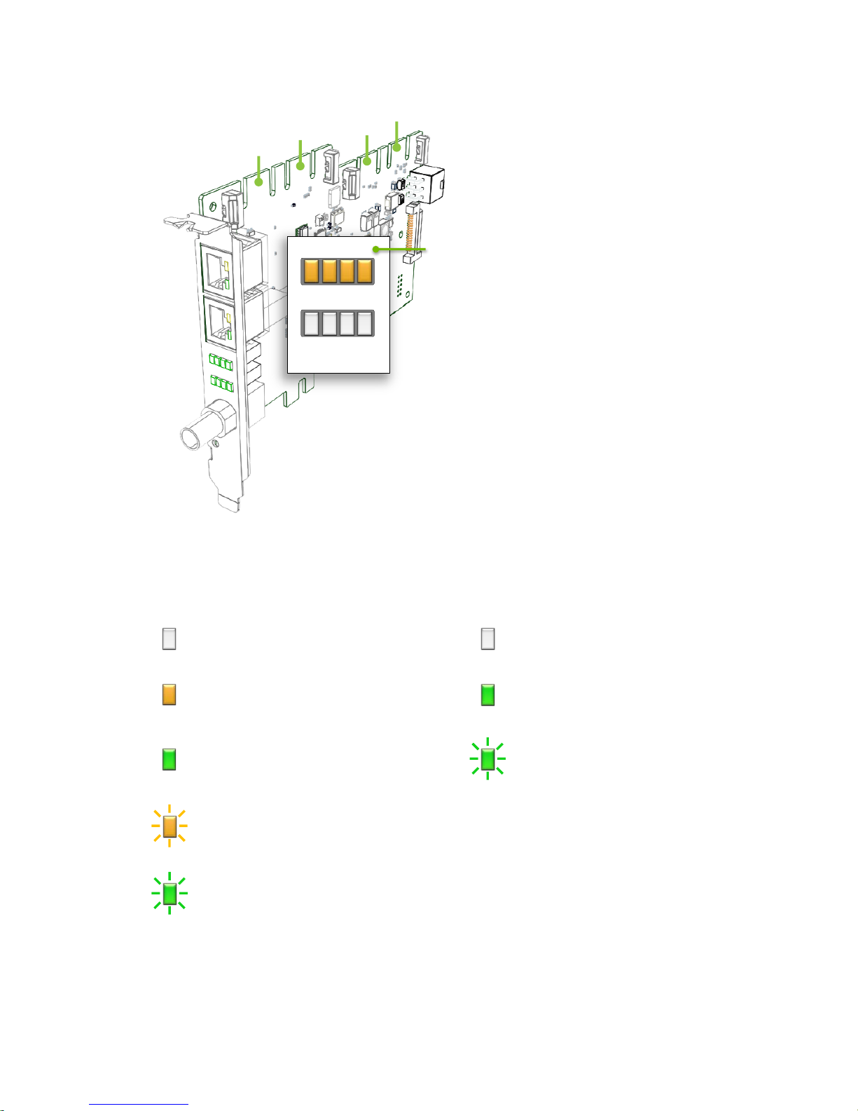
Frame Lock and Stereo Sync Status LEDs
The two rows of status LEDs provide information on the current state of
synchronization of the board. There is one LED for each of the GPUs that can be
connected.
The top row of LED’s shows the synchronization status of the connected GPUs.
Quadro Sync DU-06574-001_v01 | 24
Page 29
Monitoring Display Synchronization
SYNC LED Status
STEREO LED Status
GPU 3
GPU 2
GPU 1
GPU 0
STEREO
SYNC
0123
GPU #
Figure 7. Frame Lock and Stereo Sync Status LEDs
GPU Not connected
GPU present but not
synchronized
GPU synchronized
GPU is synchronized but within
5% of the threshold of losing sync
GPU is synchronizing
Stereo not active/no GPU
Stereo locked
Stereo in process of locking
Quadro Sync DU-06574-001_v01 | 25
Page 30

Monitoring Display Synchronization
SYSTEM TOPOLOGY VIEWER FOR WINDOWS
The System Topology Viewer provides a single screen overview of the GPU, displays
and synchronization status.
Figure 8. System Topology Viewer for Windows
Quadro Sync DU-06574-001_v01 | 26
Page 31

Monitoring Display Synchronization
To use the topology viewer:
1. Open the NVIDIA Control Panel and select View System Topology
2. With multiple GPUs and displays, the Topology Viewer can get large, maximizing
the control panel is recommended.
3. Start at the top and work down the page
a) Sync Board Settings, verify that the Framelock sync pulse and External sync
signal are as expected
b) Scroll down to the individual displays within the GPUs.
c) Verify the Timing entry for the Server is locked to the internal or external timing
d) For the other displays verify they are locked to the sync pulse and that Stereo is
in phase if using stereo
Quadro Sync DU-06574-001_v01 | 27
Page 32

SYNC TIMING LIMITS
The Quadro Sync board has the ability to align displays and sync sources up to ±20 ppm
difference in the display timings. If the timings are outside this range the board will not
be able to synchronize them. The Frame Lock status LEDs on the board will indicate that
the board is approaching these limits as well.
Table 1. Sync Timing Limits
Display Refresh Rate (Hz) Minimum (Hz) Maximum (Hz)
200 199.996 200.004
120 119.9976 120.0024
100 99.998 100.002
60 59.9988 60.0012
50 49.999 50.001
Quadro Sync DU-06574-001_v01 | 28
Page 33

COMPLIANCE AND CERTIFICATIONS
The Quadro Sync board is compliant with the following regulations:
Australian Communications Authority and Radio Spectrum Management Group of
New Zealand (C-Tick)
Bureau of Standards, Metrology and Inspection (BSMI)
China Compulsory Certification (CCC)
Conformité Européenne (CE)
Federal Communications Commission (FCC) – Class B
Interference-Causing Equipment Standard (ICES)
Imaging Science Foundation (ISF)
Korean Communication Commissions (KCC)
Underwriters Laboratories (UL, CUL)
Voluntary Control Council for Interference (VCCI)
Quadro Sync DU-06574-001_v01 | 29
Page 34

!
IMPORTANT SAFETY INFORMATION
NVIDIA products are designed to operate safely when installed and used according to
the product instructions and general safety practices. The guidelines included in this
document explain the potential risks associated with equipment operation and provide
important safety practices designed to minimize these risks. By carefully following the
information contained in this document, and the specific instructions provided with
your product, you can protect yourself from hazards and create a safer environment.
The product is designed and tested to meet IEC-60950-1, the Standard for the Safety of
Information Technology Equipment. This also covers the national implementation of
IEC-60950-1 based safety standards around the world e.g. UL-60950-1. These standards
reduce the risk of injury from the following hazards:
Electric shock: Hazardous voltage levels contained in parts of the product
Fire: Overload, temperature, material flammability
Mechanical: Sharp edges, moving parts, instability
Energy: Circuits with high energy levels (240 volt amperes) or potential as burn
hazards
Heat: Accessible parts of the product at high temperatures
Chemical: Chemical fumes and vapors
Radiation: Noise, ionising, laser, ultrasonic waves
Retain and follow all product safety and operating instructions. Always refer to the
documentation supplied with your equipment. Observe all warnings on the product and
in the operating instructions.
CAUTION: Failure to follow these safety instructions could result in fire, electric
shock, or other injury or damage.
Quadro Sync DU-06574-001_v01 | 30
Page 35

Important Safety Information
To reduce the risk of bodily injury, electric shock, fire, and damage to the equipment
observe the safety labels included on the equipment.
Table 2. Symbols on Equipment
Sign Meaning
This symbol in conjunction with any of the following
symbols indicates the presence of a potential hazard. The
potential for injury exists if warnings are not observed.
Consult your documentation for specific details
This symbol indicates the presence of hazardous energy
circuits or electric shock hazards. Refer all servicing to
qualified personnel.
WARNING: To reduce the risk of injury from electric shock
hazards, do not open this enclosure. Refer all maintenance,
upgrades, and servicing to qualified personnel.
This symbol indicates the presence of electric shock hazards.
The area contains no user or field serviceable parts. Do not
open for any reason.
WARNING: To reduce risk of injury from electric shock
hazards, do not open this enclosure.
Quadro Sync DU-06574-001_v01 | 31
Page 36

Notice
ALL NVIDIA DESIGN SPECIFICATIONS, REFERENCE BOARDS, FILES, DRAWINGS, DIAGNOSTICS, LISTS, AND OTHER
DOCUMENTS (TOGETHER AND SEPARATELY, “MATERIALS”) ARE BEING PROVIDED “AS IS.” NVIDIA MAKES NO
WARRANTIES, EXPRESSED, IMPLIED, STATUTORY, OR OTHERWISE WITH RESPECT TO THE MATERIALS, AND
EXPRESSLY DISCLAIMS ALL IMPLIED WARRANTIES OF NONINFRINGEMENT, MERCHANTABILITY, AND FITNESS FOR
A PARTICULAR PURPOSE.
Information furnished is believed to be accurate and reliable. However, NVIDIA Corporation assumes no
responsibility for the consequences of use of such information or for any infringement of patents or other
rights of third parties that may result from its use. No license is granted by implication of otherwise under
any patent rights of NVIDIA Corporation. Specifications mentioned in this publication are subject to change
without notice. This publication supersedes and replaces all other information previously supplied. NVIDIA
Corporation products are not authorized as critical components in life support devices or systems without
express written appro v al of NVIDIA Corporati on.
Trademarks
NVIDIA, the NVI DIA l ogo, Quadro, and SLI are trademarks and/or registered trademarks of NVIDIA Corporation
in the U.S. and other countries. Other company and product names may be trademarks of the respective
companies with which they are associated.
Copyright
© 2012 NVIDIA Corporation. All rights reserved.
www.nvidia.com
 Loading...