

Page 1
User’User’
User’
User’User’
ManualManual
Manual
ManualManual
ss
s
ss
nVidianVidia
nVidia
nVidianVidia
ff
or or
f
or
ff
or or
TRADEMARK
All products and company names are trademarks or registered trademarks of their
respective holders.
These specifications are subject to change without notice.
nForce 570 SLI nForce 570 SLI
nForce 570 SLI
nForce 570 SLI nForce 570 SLI
AMD SocAMD Soc
AMD Soc
AMD SocAMD Soc
kk
et et
AM2 (940-pin) AM2 (940-pin)
k
et
AM2 (940-pin)
kk
et et
AM2 (940-pin) AM2 (940-pin)
mainboardmainboard
mainboard
mainboardmainboard
prpr
ocessorocessor
pr
ocessor
prpr
ocessorocessor
6000012MF5710
Manual Revision 1.0
May 10, 2006
Page 2
DISCLAIMER OF WARRANTIES:
THERE ARE NO WARRANTIES WHICH EXTEND BEYOND THE
DESCRIPTION ON THE FACE OF THE MANUFACTURER LIMITED
WARRANTY. THE MANUFACTURER EXPRESSLY EXCLUDES ALL
OTHER WARRANTIES, EXPRESS OR IMPLIED, REGARDING ITS
PRODUCTS; INCLUDING ANY IMPLIED WARRANTIES OF
MERCHANTABILITY, FITNESS FOR A PARTICULAR PURPOSE OR
NONINFRINGEMENT. THIS DISCLAIMER OF WARRANTIES SHALL
APPLY TO THE EXTENT ALLOWED UNDER LOCAL LAWS IN THE
COUNTRY PURCHASED IN WHICH LOCAL LAWS DO NOT ALLOW OR
LIMIT THE EXCLUSION OF THE IMPLIED WARRANTIES.
HANDLING PROCEDURES:
Static electricity can severely damage your equipment. Handle the mainboard and
any other device in your system with extreme care and avoid unnecessary contact
with system components on the mainboard. Always work on an antistatic surface
to avoid possible damage to the mainboard from static discharge. Always have
the power supply unplugged and powered off when inserting and removing
devices within the computer chassis. The Manufacturer assumes no responsibility
for any damage to the mainboard that results from failure to follow instruction or
failure to observe safety precautions.
CAUTION
The mainboard is subject to damage by static electricity.
Always observe the handling procedures.
ii
Page 3
Post Port Frequently Asked Questions
Below is a list of some basic POST Codes, possible problems and solutions. For more detailed
information about POST Codes, refer to Appendix in this manual.
Post Code Problem Solution
FFh or CFh
C1h - C5h
2Dh
26h
07h - 12h
1. BI OS chip inser ted incorrectly
2. Incorrect BIOS update version
3. Mainboard problem
4. Add-on card inserted incorrectly
1. Mem o ry modu le in serted incorrec t ly
2. Mem o ry compatibility pro blem
3. Memory module damaged
1. Error occured in VGA BIOS
2. VGA card inserted incorrectly
Overclock error Clear CMOS or press the insert key to
1. Initial Keyboard c o ntroller error
2. RTC error
1. Reinsert the B IOS chip
2. Download the correct BIOS version
update from the manufacturer's
Web site
3. Replace mainboard
4. R em o ve and rep lace the add -on card
1. Reinsert memroy module
2. Replace memory with correct type
3. Replace memory module
1. Replace VGA card
2. Reinsert the VGA card
power on the system
1. Ensure the Keyboard and mouse are
connected correctly
2. Replac e the RTC battery
iii
Page 4

Table of Contents
Page
Section 1--Section 1--
Section 1--
Section 1--Section 1--
Section 2--Section 2--
Section 2--
Section 2--Section 2--
Section 3--Section 3--
Section 3--
Section 3--Section 3--
IntroductionIntroduction
Introduction
IntroductionIntroduction
1-1 Package Contents ................................................................................1
1-2 Mainboard Features .............................................................................. 2
1-3 Mainboard Specification .........................................................................4
1-4 System Block Diagram ........................................................................... 6
InstallationInstallation
Installation
InstallationInstallation
2-1 CPU Installation ....................................................................................7
2-2 Rear I/O Fan Installation ........................................................................8
2-3 Jumper Settings ...................................................................................8
2-4 System Memory Configuration ...............................................................9
2-5 Rear I/O Port........................................................................................ 10
2-6 Internal Connectors ..............................................................................10
BIOS SetupBIOS Setup
BIOS Setup
BIOS SetupBIOS Setup
3-1 Main Menu............................................................................................ 13
3-2 Standard CMOS Setup ..........................................................................14
3-3 Advanced BIOS Features ...................................................................... 14
3-4 Power BIOS Features............................................................................ 16
........................................................................................................................................................
............................................................................
........................................................................................................................................................
..............................................................................................................................................................
...............................................................................
..............................................................................................................................................................
........................................................................................................................................................
............................................................................
........................................................................................................................................................
11
1
11
77
7
77
1313
13
1313
Section 4--Section 4--
Section 4--
Section 4--Section 4--
Section 5--Section 5--
Section 5--
Section 5--Section 5--
Section 6--Section 6--
Section 6--
Section 6--Section 6--
Driver & UtilityDriver & Utility
Driver & Utility
Driver & UtilityDriver & Utility
Ghost BIOSGhost BIOS
Ghost BIOS
Ghost BIOSGhost BIOS
AppendixAppendix
Appendix
AppendixAppendix
6-1 Post Codes...........................................................................................21
..................................................................................................................................................................
.................................................................................
..................................................................................................................................................................
................................................................................................................................................
........................................................................
................................................................................................................................................
........................................................................................................................................................
............................................................................
........................................................................................................................................................
1818
18
1818
1919
19
1919
2121
21
2121
iv
Page 5
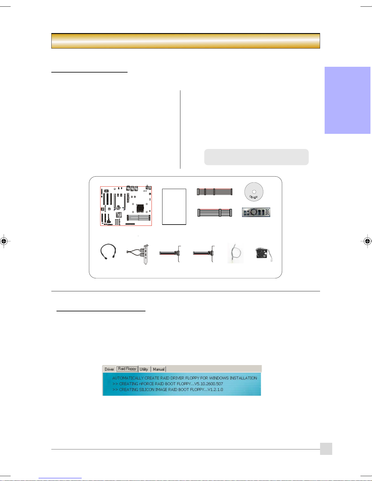
1-1 Package Contents
Introduction
Section 1 -- Introduction
Contents
A. Mainboard
B. User’s manual
C . Floppy drive cable
D. HDD drive cable
E. CD (drivers and utilities)
F. I/O Shield
G. SATA II data cable
Optional items
H. Extra USB2.0 port cable
I. COM port bracket
J . Printer port bracket
K. Thermo Stick cable
L. Rear I/O fan
If you need the optional item, please contact
your dealer for assistance.
USER’S
MANUAL
A
B
C
D
E
F
English
G
If you intend to setup RAID:
When installing Windows XP/2000 into any RAID drive, the O/S setup will require a floppy disk containing the RAID
driver. This step will show you how to prepare this driver floppy.
1. Locate a PC and insert the bundled CD into its CD-ROM drive.
2. A main menu screen will appear (Autorun feature)
3. Select the page “RAID floppy”
4. Insert a blank floppy into the A:drive
5. Click on the required RAID controller driver to begin copy into the floppy
H
I J
K
L
1
Page 6
Introduction
1-2 Mainboard Features
Socket AM2
Socket AM2 (940-pin) based motherboards are designed to provide performance enhancements for AMD Athlon
English
AM2 processor-based systems, and it also expected to be the next-generation of platform innovations.
For more information about all the new features Athlon
http://www.amd.com
at
Chipset
The board is designed with nVidia nForce 570 SLI chipset, featuring performance and stability with the most
innovative technology and features.
For more details about the nVidia chipset, please visit the nVidia Web site at
PCI-Express (PCI-E)
Next generation peripheral interface to succeed to current PCI bus for the next decade. With smaller slot size
and 250MB/sec (PCI-E*1) or 4GB/sec(PCI-E*16) maximum transfer, PCI-Express overcomes PCI bus
bottleneck.
NVIDIA SLI
NVIDIA SLi
and scalable system! Gamers and hardcore enthusiasts know that dual GPUs mean increased, supercharged
3D graphics and performance.
DDRII
DDRII ushers in the new era of DDR memory technology. DDRII memory offers faster speed, higher data
bandwidth and lower power consumption over DDR.
Dual Channel
Supports dual channel of DDRII memory to give you twice the memory bandwidth for greater system
performance.
Hardware Monitoring
Hardware monitoring enables you to monitor various aspects of the system operation and status. This
includes CPU temperature, voltage and fan speed in RPMs.
Dual GbE LAN
Onboard two Gigabit-LAN controllers. This twin set of Gigabit-LAN breaks traditional bandwidth barrier,
delivering maximum 1000Mbps between internal and external network.
Serial ATA II
S-ATA II is the second generation SATA interface with double the transferring speed up to 300MB/sec. It
supports NCQ to provide faster reading speed for your storage devices.
SATA RAID
RAID function available on chipset’s SATA II ports, RAID 0, 1, 0+1, 5 by NV driver support.
TM
technology revolutionizes PC performance by combining multiple PCI Express GPUs in a single
Brief Introduction
TM
AM2 Processor deliver, check out the AMD website
http://www.nVidia.com.
More S-ATA II (Optional)
An extra S-ATA II controller is added to allow for more S-ATA II ports expansion in the form of JMicron’s
JMB363 complete with RAID function.
e-SATA (Optional)
With this new standard, you can now hot-plug external SATA drives to your system similar to USB devices.
With transfer speed up to 6 times faster than USB2.0, RAID capabillity and Port Multiplier function, e-SATA
brings unseen before performance to storage out of the box. This function is available only on S-ATA II ports
from JMicron’s JMB363 controller.
USB2.0
A popular USB standard for plugging in peripherals with up to 480Mbps transfer speed while maintaining
backward compatibility with older USB1.1 device.
8ch
Delivers 8 channel audio to bring you the latest in audio realism from DVD movies and games. Perfect for your
home theatre system.
2
Page 7
Introduction
AMD Cool'n'QuietTM Technology
AMD's Cool'n'Quiet
reduce heat dissipation and in effect lowers the fan speed to noise from your PC.
NVIDIA Firewall (Optional)
An unprecedented addition design for nForce product, provide high performance & enhanced reliability of PC
security solution to the users. The features would be more advanced than many stand-alone firewalls can
provide!
NVIDIA ActiveArmorTM (Optional)
Enhances networks security while delivers the highest system performance by off-loading CPU-intensive
packet filtering tasks in hardware, providing users with a PC networking environment that is both fast and
secure.
TM
Technology lowers CPU operating voltage when the system is in idle mode. This helps to
Special Features
BIOS Features:
Ghost BIOS
No more worries if BIOS gets corrupted causing your system unable to boot. The onboard backup BIOS will
rescue & recover main BIOS in just a few easy steps.
Thunder Probe
A hardware diagnostic software to monitor voltage, temperature and speed of a variety of hardware. It also
includes an ingenious built in fan control feature called Smart Fan.
Thunder Flash
A Windows based innovation tool to provide safe and easy BIOS rescue function, BIOS flash function and
personal start up screen.
Magic Health
Reports your system hardware status for every boot-up to help detect faults early. Monitor hardware status
including CPU temperature, CPU/Memory/Chipset voltage, fan RPM speed for chassis fan, CPU fan & Power
supply fan.
EZ-Boot
Simply press “ESC” to select your bootable device. No more hassle to search the BIOS menu, change and
re-start.
PowerBIOS
Supporting a full range of overclocking setting via BIOS. Various adjustable feature include FSB/Memory/
Chipset voltage tweaking.
English
H/W Features:
Post Port
An onboard LED-display trouble-shooting device, facilitating user to detect boot-up problems.
QuickSPDIF
On board SPDIF-out connector for quick connection to multi-channel speakers. Not only removes cable
cluttering but also delivers loss-free digital audio to let you enjoy DVD movies and games with crystal clear
sound.
EZ-Button
A handy power-on button located onboard to turn on/off the system easily, especially while debugging or
testing the system.
LEDION
Onboard LED indicators to show the power status CPU, Chipset and DRAM. You know immediately where to
look if the system fails to start.
Thermo Stick (Optional)
Flexible thermometer to let you measure any temperature by software. Ideal for monitoring VGA card,
chipset or even disk drives temperatures.
3
Page 8
Introduction
1-3 Mainboard Specification
Processor
Support Socket-AM2 (940-pin) based AMD Athlon-AM2 with 2GTs 16x16 Hyper Transport processors
Support VMM (Virtualization-Machine-Monitoring)
English
Chipset
nVidia nForce 570 SLI
Main Memory
Four 240-pin unbuffered non-ECC DDRII SDRAM DIMM sockets
Support single-sided or double-sided 1.8v DDRII-533/667/800 DIMMs with dual channel architecture in
256Mb/512Mb/1Gb technologies
Supports up to 16GB memory size
Expansion Slots
Three PCI connectors compliant with PCI v2.3
Two PCI-E (x1) connectors compliant with PCI Express 1.0a
Two PCI-E (x16) connectors compliant with PCI Express 1.0a to support SLi technology
USB
Ten USB connectors compliant with USB2.0 from embedded USB controller (4 connectors at rear panel)
LAN
Two Gigabit Ethernet from onboard Marvell 88E1116 Gigabit Ethernet PHY
P-ATA IDE
One IDE interface (up to 2 IDE devices) with UDMA-33/66/100/133 support from embedded IDE controller
S-ATA RAID
Six S-ATA II ports with up to 300MB/s from chipset with RAID 0, 1, 0+1, 5
More S-ATA (Optional)
Two S-ATA II ports and One P-ATA port from JMicron's JMB363 PCI-Express to 2S1P controller and e-SATA
support.
I/O
Onboard EPoX EP1308 LPC bus I/O controller
Legacy peripheral interface for PS/2 keyboard & mouse, FDD, Parallel, Serial, and IrDA (v1.0 compliant)
Support Hardware Monitoring for fan speed monitoring and CPU temperature sensing
Intelligent fan speed control for CPU-fan (PWM) and Chassis-fan for quiet operation
Audio
8 channel audio from onboard Realtek ALC8xx High Definition audio compliant CODEC
- Support CD-In
- Support Jack detection for fool-proof audio device installation
- Rear panel audio jacks configuration:
roloCkcaJenohP lennahc2 lennahc6 lennahc8
eulBthgiLni-eniLni-eniLni-eniL
emiLtuo-eniLtuo-oeretstnorFtuo-oeretstnorF
kniPni-ciMni-ciMni-ciM
yarGtuo-oeretsediS
kcalBtuo-oeretsraeRtuo-oeretsraeR
egnarOrefoowbuS&retneCrefoowbuS&retneC
4
Page 9

BIOS
Flash EEPROM with Award Plug&Play BIOS
Support EZ Boot for fast bootable device selection
Support Magic Health for system hardware status report during system boot-up
Support Ghost BIOS for BIOS Recovery
Peripheral Interfaces
))
) At Rear Panel
))
PS/2 keyboard and mouse ports
One S/PDIF-Out Coaxial jack
One S/PDIF-Out Optical
One RJ45 LAN connector
Four USB2.0 ports
Six Audio jacks
))
) Onboard connector and pin-header
))
One floppy drive connector
One ATA-100/133 IDE connector from nVidia nForce 570 SLI
One ATA-100/133 IDE connector from JMicron’s JMB363 (Optional)
Six extra USB2.0 ports
One CD-IN connector
One IR connector
One Parallel (printer) connector
One Serial port (COM1) connector
Six S-ATA II connectors from nVidia nForce 570 SLI
Two S-ATA II connectors from JMicron’s JMB363 (Optional)
Four Fan connectors
Introduction
English
Front Panel Controller
Supports Reset & Soft-Off switches
Supports HDD & Power LEDs
Supports PC speaker
Supports Front Panel Audio connector
Special Features
Support KBPO function – Keyboard power on, turn on the computer from keyboard
Support Wake-On-LAN by PME
Onboard Post Port LED display for system debugging
PowerBIOS for excellent overclocking features:
- Programmable FSB and PCI-E Clock output frequency with 1MHz fine tuning
- Support BIOS adjustable CPU multiplier, FSB clock, PCI-E x16 clock, DIMM frequency
- Support BIOS adjustable CPU Core voltage, Chipset voltage and DIMM voltage
Support EZ-Button – A handy power-on button onboard to turn on/off the system easily
Support LEDION – onboard LED power indicator for CPU, DDR and chipset
Support Thermo Stick temperature (Optional)
Support Ghost BIOS - Rescue, recover BIOS in an easy step and no more worry of BIOS being corrupted.
Powerful utilities for Windows
Support Thunder Probe - A hardware diagnostic software to monitor voltage, temperature and speed of
a variety of hardware. It also includes an ingenious built in fan control feature called Smart Fan.
Support Thunder Flash - A Windows based innovation tool to provide safe and easy BIOS rescue
function, BIOS flash function and personal start up screen.
5
Page 10
Introduction
Form Factor
305mm x 245 mm A TX size
Depending on the model you purchased, some components are optional and may not be
available.
English
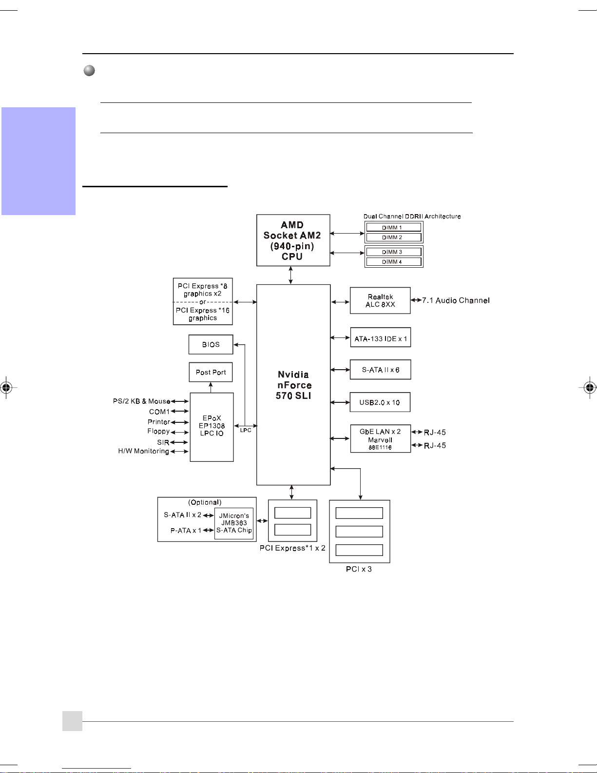
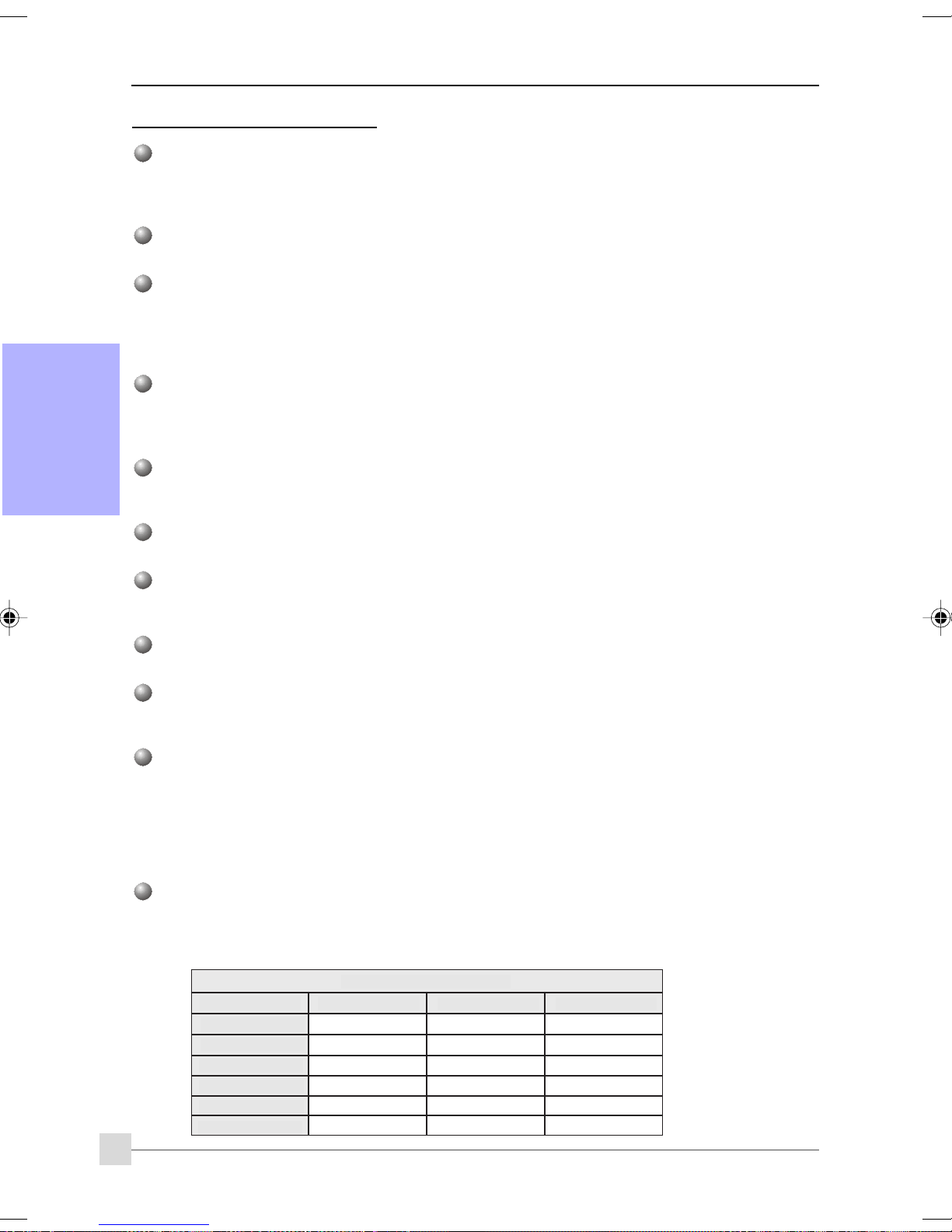
1-4 System Block Diagram
6
Page 11
Always have the power supply unplugged and powered off when
inserting and removing devices within the computer chassis.
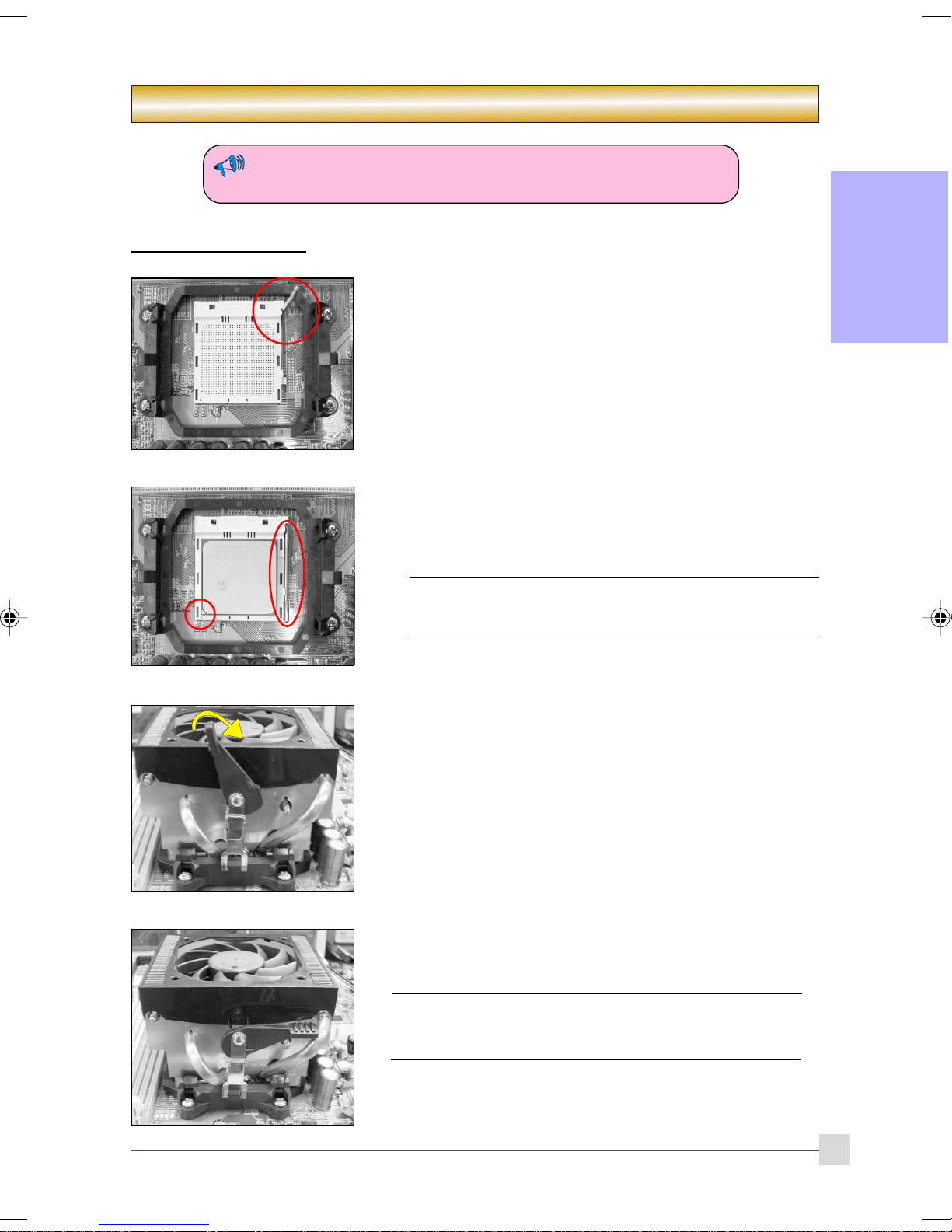
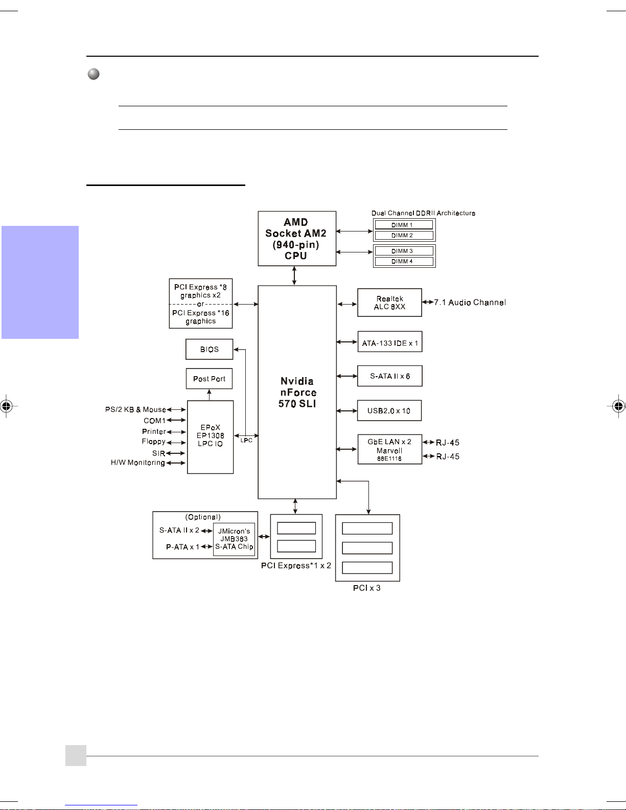
2-1 CPU Installation
Introduction
Section 2 -- Installation
(1)
(2)
Step 1
Open the socket by raising the actuation lever.
Step 2
(1) Align pin 1 on the CPU with pin 1 on the CPU socket as shown.
Insert the CPU and make sure it is fully inserted into the socket.
(2) Close the socket by lowering and locking the actuation lever.
The CPU is keyed to prevent incorrect insertion, do not force
the CPU into the socket. If it does not go in easily, check for
mis-orientation.
Step 3
Insert the heatsink as shown. Press the clips in the direction of the
arrows shown to secure the assembly to the CPU socket.
English
Step 4
Plug the CPU fan power into the mainboard’s CPU fan connector.
The installation is complete.
• Thermal compound and qualified heatsink recommended by
AMD are a must to avoid CPU overheat damage.
• Apply heatsink thermal compound/paste to the CPU.
7
Page 12
Introduction
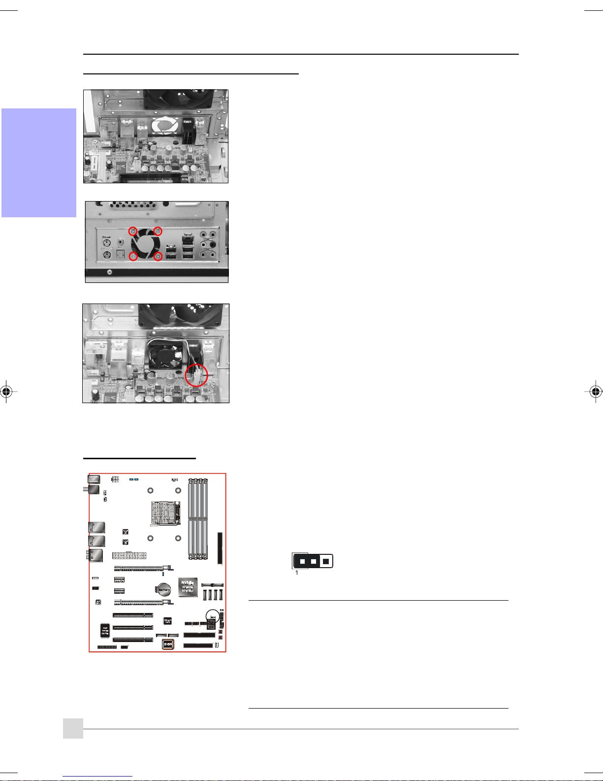
2-2 Rear I/O Fan Installation (Optional)
English
Step 1 :
First install the I/O shield and the mainboard to the computer
case as shown on the left.
Step 2 :
Place the fan behind the I/O shield and tighten it with the 4
screws included in the package.
Step 3 :
Plug the power to the 3-pin header JFAN2. Fan installation is
now complete.
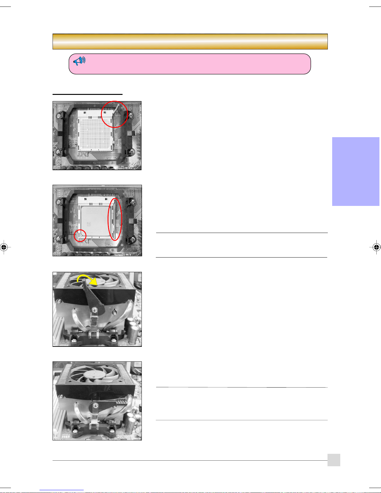
2-3 Jumper Settings
8
JCMOS: Clear CMOS data Jumper
If the CMOS data becomes corrupted or you forgot the supervisor or
user password, clear the CMOS data to reconfigure the system back to
the default values stored in the ROM BIOS.
Settings:
1-2: Normal (Default)
2-3: Clear CMOS
To CMOS Clear data, please follow the steps below.
1. Turn off the system.
2. Change the jumper from “1-2” to “2-3” position for a few
seconds.
3. Replace the jumper back to the “1-2” position.
4. Turn on the system and hold down the <Del> key to enter
BIOS setup.
Page 13

Introduction
2-4 System Memory Configuration
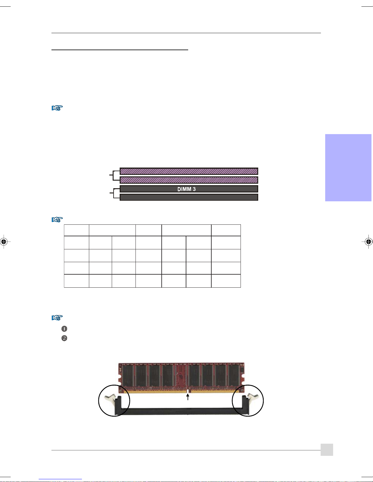
The mainboard accommodates Four 240-pin DIMMs.
• Supports up to 16GB of 533/667/800MHz DDRII SDRAM.
• Supports unbuffered DIMM configurations defined in JEDEC DDRII DIMM specification.
Dual Channel interface:
• Dual channel memory access offers increased system performance.
• For dual channel to operate, both channel must be populated with same amount of memory, preferably
of the same type.
• The four DIMM sockets are divided into two colors to help you identify the channel pairs <Figure 1>. Each
dual channel pair has the same color, e.g. DIMM1 and DIMM2. To obtain best performance, simply
mount DIMM sockets of the same color.
English
Dual Channel 1
DIMM 1
<Figure 1>
DIMM 2
Dual Channel 2
DIMM 4
Memory configurations supported:
MMID1
)tib-46(
1#MMIDSD/SSSD/SSSD/SSSD/SS
2#MMIDSD/SSSD/SS
3#MMIDSD/SSSD
4#MMIDSD/SSSD/SS
MMID2
)tib-46(
/SSSD/SSSD/SS
MMID2
)tib-821(
MMID4
)tib-821(
* SS: Single-Sided DIMM, DS: Double-Sided DIMM
Memory Installation :
To install, align the notch on the DIMM module with the connector.
Press straight down as shown in the figure until the white clips close and the module fits tightly into the
DIMM socket.
Notch
9
Page 14
Introduction
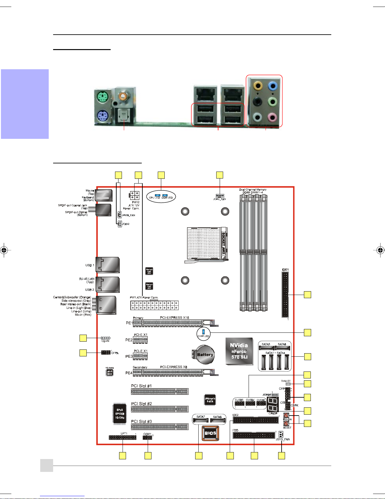
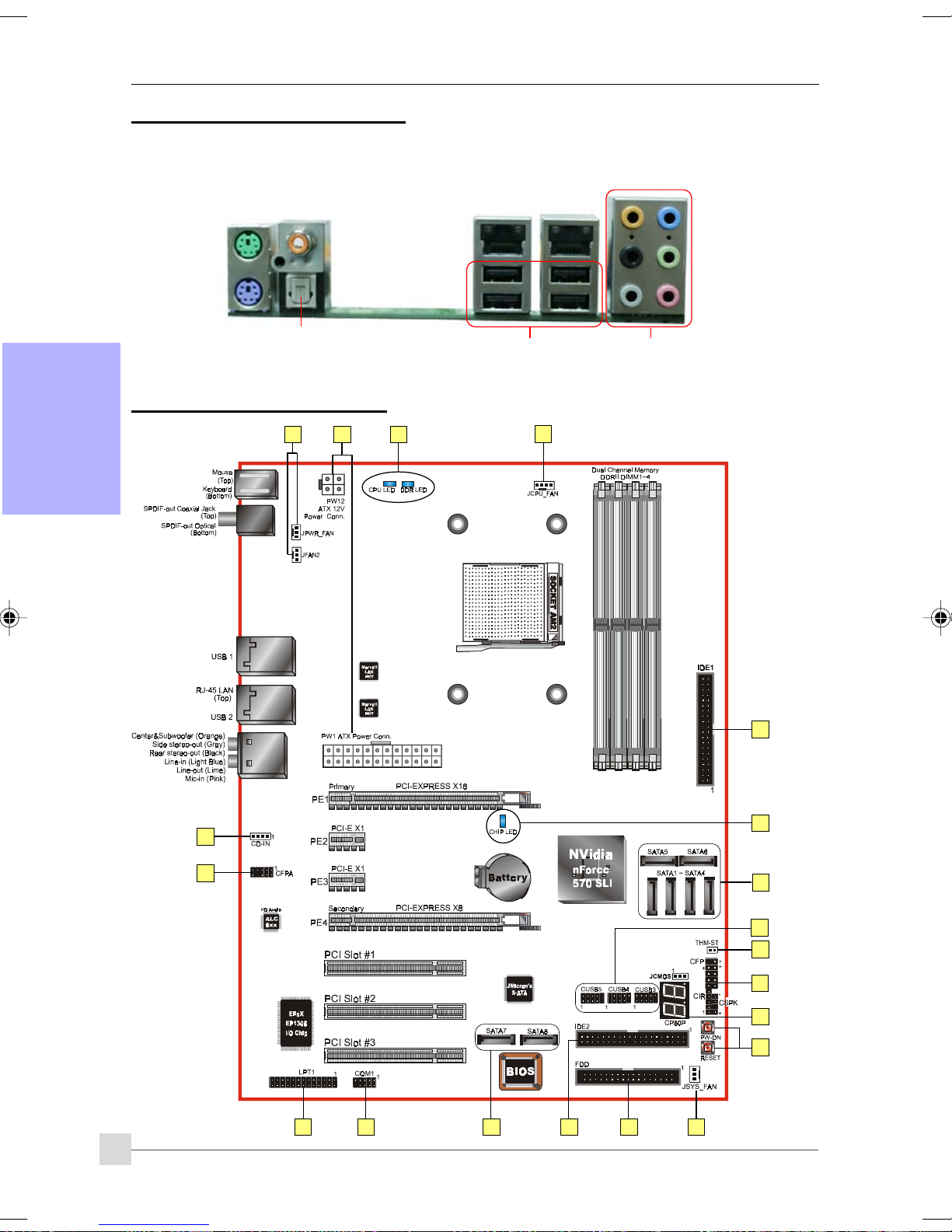
2-5 Rear IO Port
The I/O back panel for this mainboard is shown below. When installing the mainboard into the computer case, use the
bundled I/O shield to protect this back panel.
English
PS/2
Mouse
PS/2
Keyboard
2-6 Internal Connectors
S/PDIF-out
Coaxial Jack
S/PDIF-out Optical
1 4
11
RJ45
LAN
USB2.0 x 4 ports
RJ45
LAN
1
7.1 Audio Channel
10
3
11
6
5
9
7
13
8
14
15
12
1016
3
2
1
Page 15
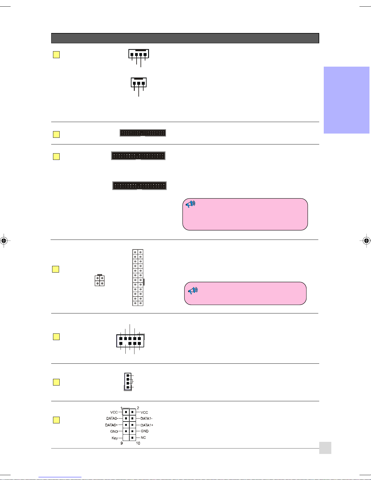
Connectors Figure Descriptions
Introduction
JCPU_FAN
1
JPWR_FAN
JSYS_FAN
JFAN2
FDD
2
IDE1
3
Primary IDE
IDE2
Secondary IDE
(Optional)
CPU / Power / Chassis /IO Fan Power Connectors
Control
Sense
Ground
+12V
JCPU_FAN: Connect the CPU fan to this connector.
JPWR_FAN: Use this connector if you are installing an
additional fan in the unit.
JSYS_FAN: The chassis fan will provide adequate airflow
Ground
Sense
+12V
throughout the chassis to prevent overheating
the CPU.
JFAN2: If you are installing the rear I/O fan in the unit,
connect to this fan connector.
English
Floppy Drive Connector
1
Primary IDE Connector
1
Connects to the IDE device, i.e. HDD and CD-ROM device.
Secondary IDE Connector
1
Connects to the HDD device only.
When using two IDE drives on the same
connector, one must be set to Master mode
and the other to Slave mode. Refer to your
disk drive user’s manual for details.
4
5
6
7
PW1
PW12
CFPA
CD-IN
CUSB3
CUSB4
CUSB5
4
3
+12V+12V
GroundGround
2
1
Front Line-out-L
23
24
3.3V
+12V
+12V
Front Line-out-R
NC
91
10
NC
Key
1
11
1
NC
MIC_ In
NC
GND
+5V
CD_IN_Right
CD_Reference
CD_IN_Left
Ground
+5V
+5V
+5V5VSB
-5VPW-OK
GroundGround
Ground+5V
GroundGround
PS-ON+5V
GroundGround
-12V3.3V
3.3V3.3V
2
PW1: 24-pin ATX Power Connector
PW12: 4-pin ATX12V Power Connector
The plugs of the power cables are designed to fit in only one
orientation.
The PW1 and PW12 Power Connector must
be used simultaneously.
CFPA: Front Panel Audio Connector
This audio connector connects to the audio jacks located on the
front panel. Refer to your case manual to match the pin-out
names.
CD-IN: CD Audio-in connectors
This connector is used to receive audio from a CD-ROM drive,
TV tuner or MPEG card.
CUSB3/CUSB4/CUSB5: Six USB2.0 header
This mainboard includes 6 additional onboard USB ports.
To use these additional USB ports, a USB bracket is required.
Please contact your retailer for details.
11
Page 16
Introduction
8
English
Connectors Figure Descriptions
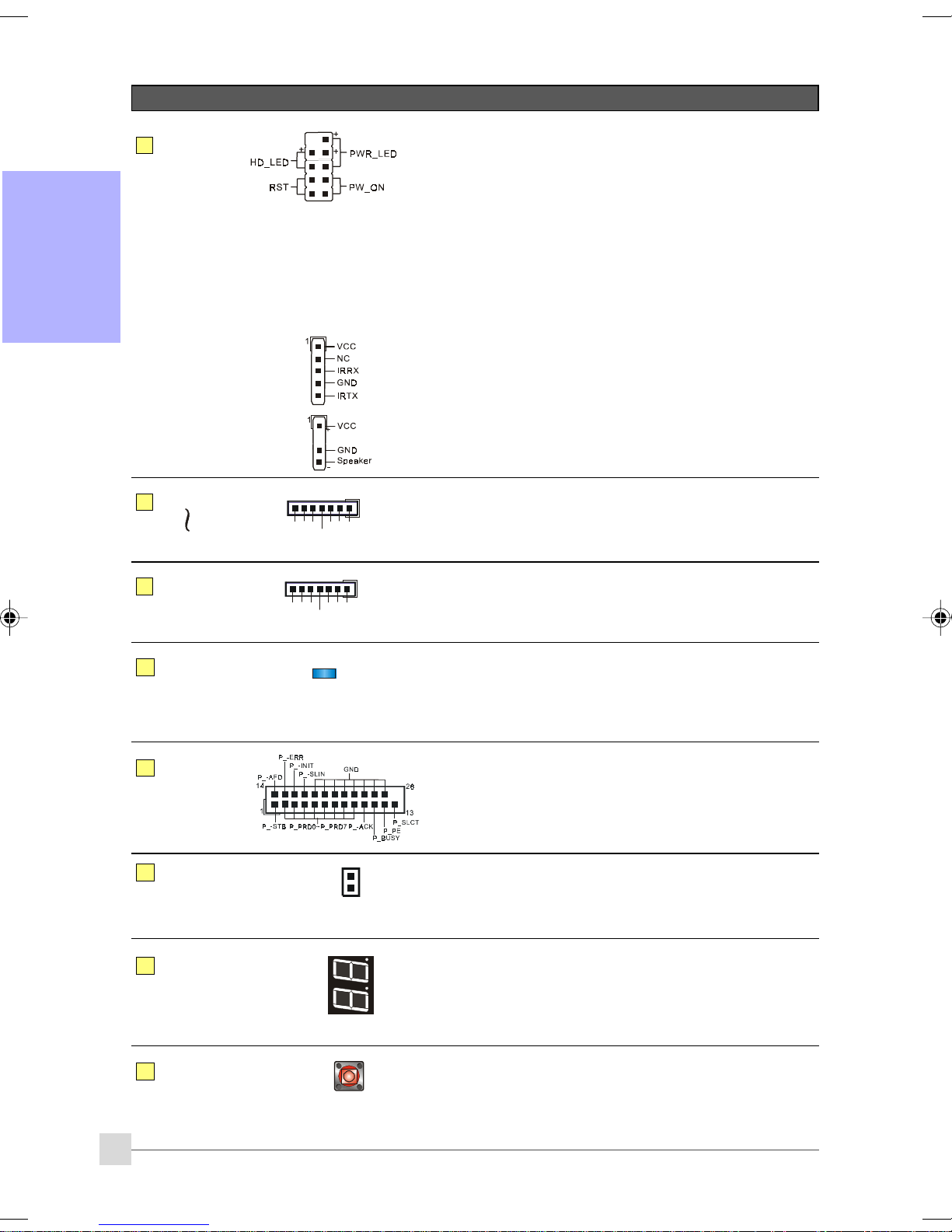
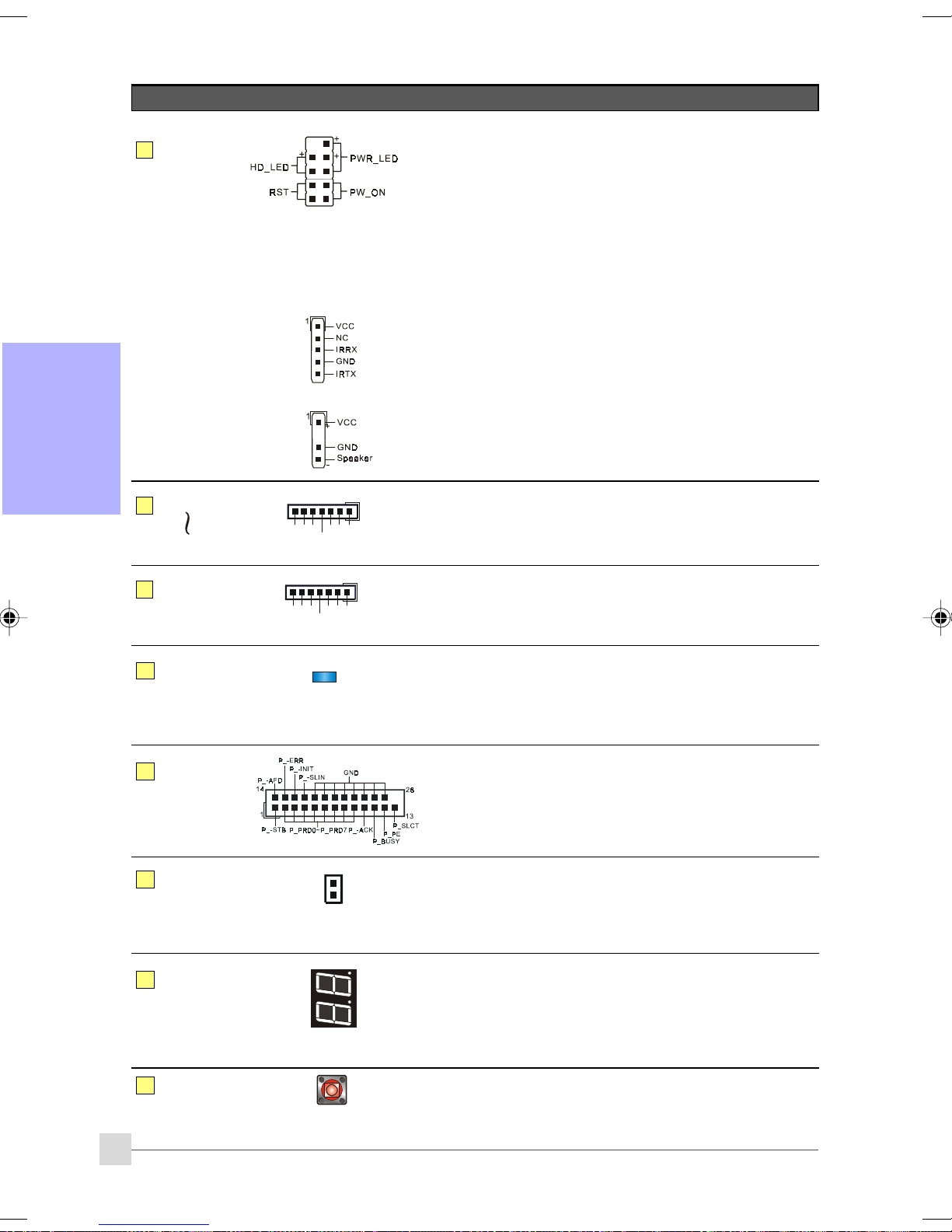
CFP: Case Front Panel Connector
CFP
CIR
HD_LED
This LED indicates hard drive activity.
PWR_LED
Connects to the power indicator on the PC case.
RST
Connects to the RESET switch on the PC case.
PW_ON
Connects to the Power button on the PC case, to turn on
the system. To turn off the system, press the power
button for 4 seconds.
CIR: IR connector
For connection to an IrDA receiver unit.
9
10
11
12
13
CSPK
SATA1
SATA6
SATA7
SATA8
(Optional)
LEDION
LPT1
THM-ST
(Optional)
GND
GND
CSPK: Speaker
Connects to the case’s speaker for PC beeps.
1
A+
GND
B+
A-B-
GND
1
B+
A+
GND
A-B-
GND
SATA1 ~ SATA6: Six S-ATA II Connectors
These connectors enable you to connect Serial ATA HDDs or
optical drives type.
SATA7 ~ SATA8: Two S-ATA II Connectors
These connectors enable you to connect Serial ATA HDDs or
optical drives type with e-SATA.
LEDION:
Onboard LED indicators to show the power status of CPU,
Chipset and DRAM. You know immediately where to look if the
system fails to start.
LPT1: Parallel Port (printer) Connector
The parallel port can be used for printers and other parallel
device.
Thermo Stick:
Flexible thermometer to let you measure any temperature by
software. Ideal for monitoring VGA card, chipset or even disk
drives temperatures.
CP80P
14
EZ-Button
15
12
CP80P: Post Port Debug LED
Provides two-digit POST code to show why the system fail to
boot. Allows quick and easy optimization.
The LED will display the CPU temperature when you run the
bundled Thunder Probe software.
EZ-Button — RESET, PW-ON:
These onboard buttons lets you turn on/off the system
easily, it is especially handy for debugging or testing the
system.
Page 17
Introduction
Connectors Figure Descriptions
16
COM1
RI
DSR
CTS
TXD
DTR
10
9
Ground
2
1
DCD
RXD
COM1: Serial Port Connector
The serial port can be used with modems, serial printers,
remote display terminals, and other serial device.
RTS
Section 3 -- BIOS Setup
3-1 Main Menu
The ROM BIOS contains a built-in Setup program which allows user to modify the basic system configuration and
hardware parameters. The modified data is stored in a battery-backed CMOS, so that data will be retained even
when the power is turned off. In general, the information saved in the CMOS RAM will stay unchanged unless there
is a configuration change in the system, such as hard drive replacement or a device is added.
It is possible for the CMOS battery to fail causing CMOS data loss. If this happens you will need install a new CMOS
battery and reconfigure your BIOS settings.
The BIOS setup screen and description are for reference only, and may not exactly match
what you see on your screen. The contents of BIOS are subject to change without notice.
Please visit our website for BIOS updates.
English
To enter the Setup Program :
Power on the computer and press the <Del> key during the POST (Power On Self Test). The BIOS CMOS SETUP
UTILITY opens.
The main menu displays all the major selection items. Select the item you need to reconfigure. The selection is made
by moving the cursor, press any direction (arrow key ) to the item and pressing the ‘Enter’ key. An on-line help
message is displayed at the bottom of the screen as the cursor is moved to various items which provides a better
understanding of each function. When a selection is made, the menu of the selected item will appear so that the user
can modify associated configuration parameters.
For more information regarding BIOS settings refer to the complete manual in the
bundled CD.
13
Page 18
Introduction
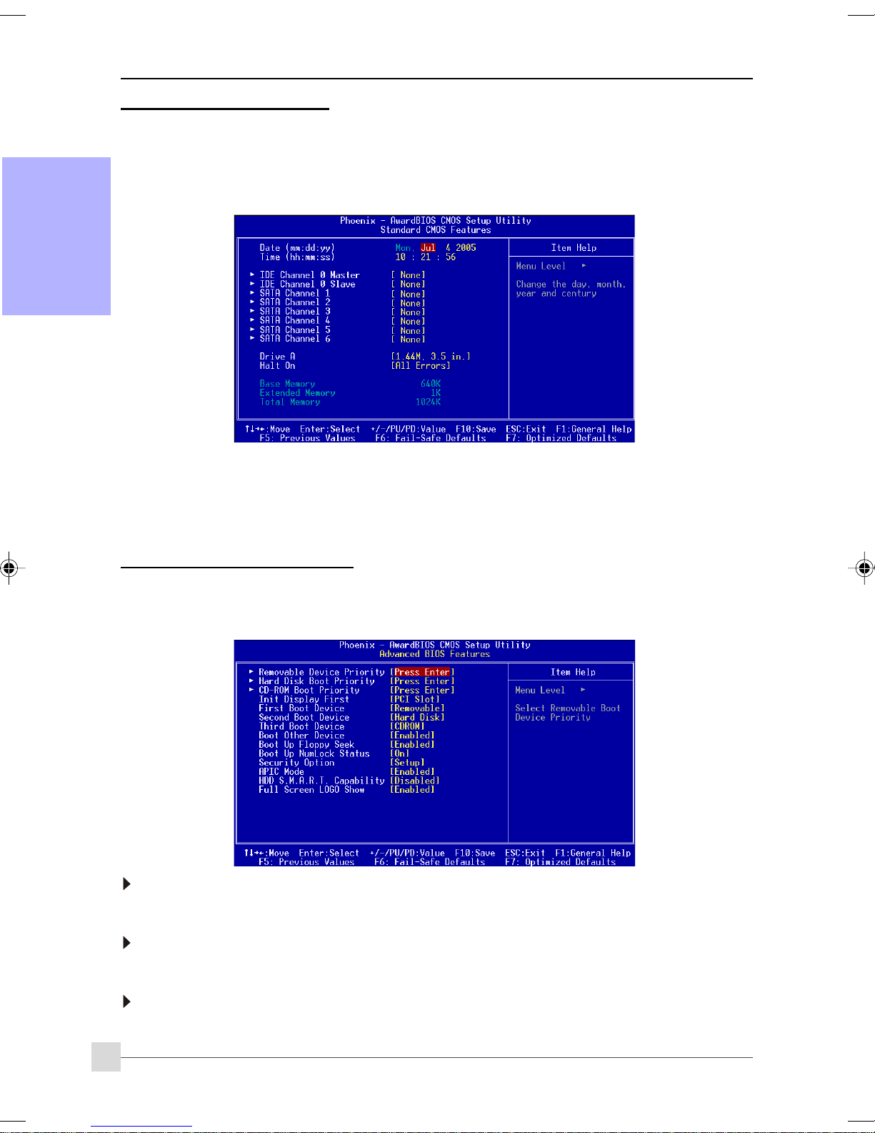
3-2 Standard CMOS Setup
Choose “STANDARD CMOS FEATURES” in the CMOS SETUP UTILITY Menu. Standard CMOS Features Setup allows the
user to configure system settings such as the current date and time, type of hard disk drive installed, floppy drive
type, and display type. Memory size is auto-detected by the BIOS and displayed for your reference. When a field is
highlighted (use direction keys to move the cursor and the <Enter> key to select), the entries in the field can be
changed by pressing the <PgDn> or the <PgUp> key.
English
Notes:
• If the hard disk Primary Master/Slave and Secondary Master/Slave are set to Auto, the hard disk size and
model will be auto-detected.
• The “Halt On:” field is used to determine when the BIOS will halt the system if an error occurs.
3-3 Advanced BIOS Features
Selecting the “ADVANCED BIOS FEATURES” option in the CMOS SETUP UTILITY menu allows users to change system
related parameters in the displayed menu. This menu shows all of the manufacturer’s default values for the board.
Pressing the [F1] key displays a help message for the selected item.
Removable Device Priority
This item allows you to select the hard disk boot priority.
Options: Floppy, LS120, ZIP100, USB-FDD0, USB-FDD1, USB-ZIP0, USB-ZIP1.
Hard Disk Boot Priority
This item allows you to select the hard disk boot priority.
Options: Pri. Master, Pri. Slave, Sec. Master, Sec. Slave, USBHDD0, USBHDD1, USBHDD2, Bootable Add-in cards.
CD-ROM Boot Priority
This item allows you to select the CD-ROM boot priority.
Options: Pri. Master, Pri. Slave, Sec. Master, Sec. Slave, USB-CDROM0, USB-CDROM1.
14
Page 19

Introduction
Init Display First
This item is used to select whether to initialize the PCI-E or PCI first when the system boots.
Options: PCI Slot, PCIEx.
First /Second/Third Boot Device
The BIOS attempts to load the operating system from the devices in the sequence selected in these items.
Options: Floppy, LS120, Hard Disk, CDROM, ZIP100, USB-FDD, USB-ZIP, USB-CDROM, Legacy LAN, Disabled.
Boot Other Device
When enabled, the system searches all other possible locations for an operating system if it fails to find one in the
devices specified under the first, second, and third boot devices.
Options: Enabled, Disabled.
Boot Up Floppy Seek
If this item is enabled, it checks the size of the floppy disk drives at start-up time. You don’t need to enable this item
unless you have a legacy diskette drive with 360K capacity.
Options: Enabled, Disabled.
Boot Up NumLock Status
This controls the state of the NumLock key when the system boots.
On: The keypad acts as a 10-key pad.
Off: The keypad acts like cursor keys.
Security Option
This category allows you to limit access to the System and Setup, or just to Setup.
System: The system will not boot and access to Setup will be denied unless the correct password is
entered at the prompt.
Setup: The system will boot, but access to Setup will be denied unless the correct password is
entered at the prompt.
APIC Mode
This item allows you to enable APIC (Advanced Programmable Interrupt Controller) functionality.
Options: Enabled, Disabled.
HDD S.M.A.R.T. Capability
The S.M.A.R.T. (Self-Monitoring, Analysis, and Reporting Technology) system is a diagnostics technology that
monitors and predicts device performance. S.M.A.R.T. Software resides on both the disk drive and the host
computer. If a device failure is predicted, the host software, through the Client WORKS S.M.A.R.T applet, warns the
user of the impending condition and advises appropriate action to protect the data.
Options: Enabled, Disabled.
Full Screen LOGO Show
This item allows you determine Full Screen LOGO display during POST.
Options: Enabled, Disabled.
English
15
Page 20
Introduction
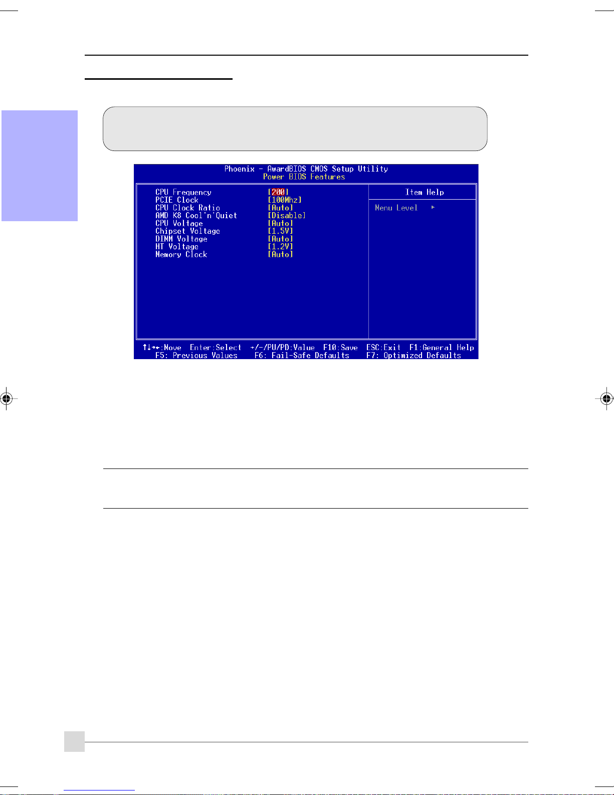
3-4 POWER BIOS Features
This page lets you adjust various parameters to obtain improved performance for overclocking.
Warning:
Overclocking requires expert knowledge and risks permanent damage to system components.
English
We recommend you leave these parameters at their default values for proper operation.
CPU Frequency
Enables you to increment the CPU’s clock generator at 1 MHz step. This works together with CPU Clock Ratio (below)
to set the CPU operating frequency.
CPU Clock Generator x CPU Clock Ratio = CPU Frequency
For example, if you have a processor that is rated at 2.4GHz and the clock generator is 200MHz, then 200MHz x 12
= 2.4GHz
Options: 200 to 450 in 1MHz increments.
Overclocking failure will cause no display on the monitor. To overcome this switch off the power supply
and switch on again. Restart the system, press and hold <
default or initial setting.
PCIE Clock
Enables you to subtle tune the PCIE frequency at increments of 1MHz step.
Options: 100 to 145 in 1MHz increments.
CPU Clock Ratio
Use this item to select a multiplier to set the CPU frequency. See CPU Frequency item above for explanation. If your CPU
multiplier is locked this option will be unavailable.
AMD K8 Cool’n’Quiet
Reduce the noise and heat from you PC when AMD’s Cool’n’Quiet
Options: Auto, Disabled.
CPU Voltage
This item allows you to adjust the CPU Vcore voltage.
Options: Auto, -0.200V to +0.500V in 0.025V increments. We recommend that you leave this at the default value.
Chipset Voltage
This item allows you to adjust the Chipset voltage.
Options: +1.5V to +1.8V in 0.1V increments. We recommend that you leave this at the default value.
DIMM Voltage
This item allows you to adjust the DIMM slot voltage.
Options: Auto, +1.8V to +2.5V in 0.1V increments. We recommend that you leave this at the default value.
Insert>
TM
technology is Auto.
key. This will revert the BIOS to
16
Page 21
HT Voltage
This item allows you to adjust the HT voltage.
Options: 1.2V to 1.5V in 0.1V increments. We recommend that you leave this at the default value.
Memory clock
This item sets the memory clock.
CPU Core Clock Multiplier vs. DRAM Interface Speed
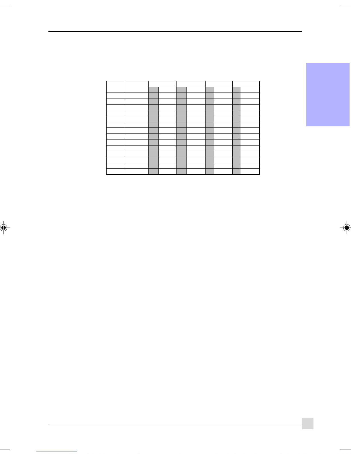
CPU Ratio
CPU Frequency
4 800 MHz 5 160MHz 5 160MHz 5 160MHz 5 160MHz
5 1000 MHz 5 200MHz 5 200MHz 5 200MHz 5 200MHz
6 1200 MHz 6 200MHz 5 240MHz 5 240MHz 5 240MHz
7 1400 MHz 7 200MHz 6 233MHz 5 280MHz 5 280MHz
8 1600 MHz 8 200MHz 6 266MHz 5 320MHz 5 320MHz
9 1800 MHz 9 200MHz 7 257MHz 6 300MHz 5 360MHz
10 2000 MHz 10 200MHz 8 250MHz 6 333MHz 5 400MHz
11 2200 MHz 11 200MHz 9 244MHz 7 314MHz 6 366MHz
12 2400 MHz 12 200MHz 9 266MHz 8 300MHz 6 400MHz
13 2600 MHz 13 200MHz 10 260MHz 8 325MHz 7 371MHz
14 2800 MHz 14 200MHz 11 254MHz 9 311MHz 7 400MHz
15 3000 MHz 15 200MHz 12 250MHz 9 333MHz 8 375MHz
16 3200 MHz 16 200MHz 12 266MHz 10 320MHz 8 400MHz
17 3400 MHz 17 200MHz 13 261MHz 11 309MHz 9 377MHz
100 MHz 133 MHz 166 MHz
DIV Freq. DI V Freq. DIV Freq. DIV Fr eq.
200 MHz
* Memory Frequency = CPU Frequency / Division
Introduction
English
17
Page 22
Introduction
Section 4 -- Driver & Utility
Once the operating system has been installed, you need to install the drivers for the mainboard.
English
Please select:
Method 1
Method 2
Insert the bundled CD into the CD-ROM and the main menu screen will appear. The main menu displays links to
the supported drivers, utilities and software.
Method 1
This item installs all drivers automatically.
Method 2
This item allows you to install the drivers selectively.
Auto Installation
Manual Installation
Please install SP1 for Windows XP before installing nForce driver
>> nVIDIA nForce Driver
>> REALTEK High Definition Audio Driver
>> USB 2.0 Driver
>> JMicron PCI Express SATA II and PATA Controller Driver
>> AMD Cool’n’Quiet Processor Driver
Step 1 : Click “nVIDIA nForce Driver” to install chipset driver.
Step 2 : Click “REALTEK High Definition Audio Driver” to install audio driver.
Step 3 : Click “USB V2.0 Driver” to install USB 2.0 driver.
Step 4 : Click “JMicron PCI Express SATA II and PATA Controller Driver” to install JMicron PCI
Express SATA II and PATA Controller driver.
Step 5 : Click “AMD Cool’n’Quiet Processor Driver” to install AMD series processor driver.
Main menu items may vary depending on model you purchased.
Once the drivers have been successfully installed, you may proceed to install the bundled utility software.
18
Page 23
Introduction
Section 5 -- Ghost BIOS
Ghost BIOS helps you to recover from a corrupted BIOS situation, which normally would leave your system unable to
boot. Ghost BIOS lets you repair the BIOS yourself saving the hassle of returning the mainboard for repair.
Preparing for Ghost BIOS:Preparing for Ghost BIOS:
Preparing for Ghost BIOS:
Preparing for Ghost BIOS:Preparing for Ghost BIOS:
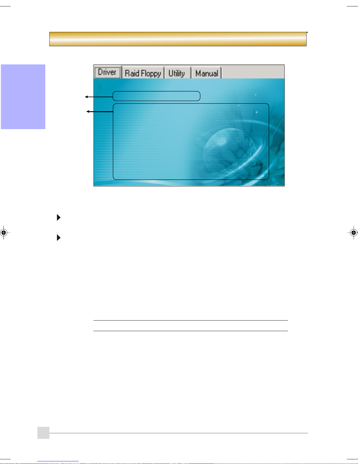
1. Install the Thunder Flash utility found in the bundled CD.
2. Create a BIOS Recovery Disk (BRD) with this utility.
“LOAD”
Making BIOS Recovery Disk:
1. Run the Thunder Flash utility.
2. Connect to the internet.
3. Insert a blank floppy disk into floppy drive and click "LOAD".
4. Keep this floppy in a safe place for future use.
IfIf
BIOS g BIOS g
If
BIOS g
IfIf
BIOS g BIOS g
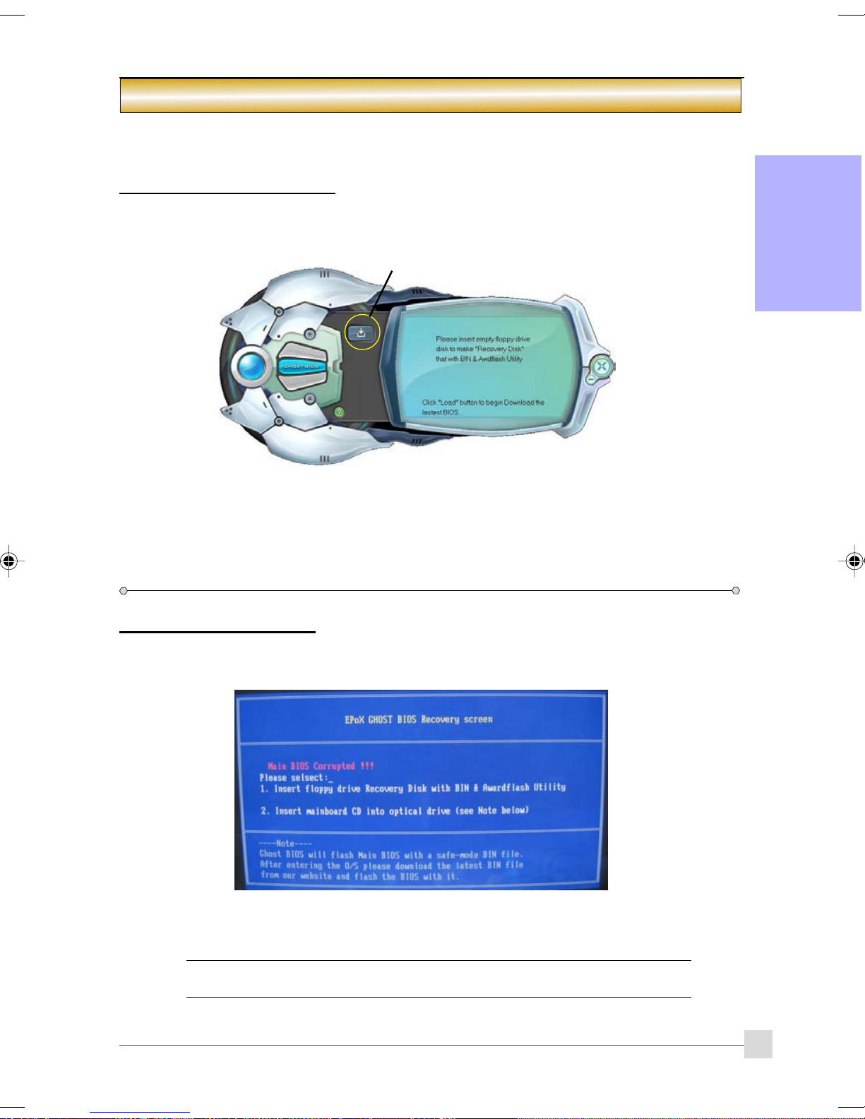
When the BIOS is corrupted or fails, restart the system and this screen will appear. You may chose to recover the
BIOS from BRD Floppy created earlier or from bundled driver CD.
ets corets cor
ets cor
ets corets cor
rr
upted:upted:
r
upted:
rr
upted:upted:
English
1. If recover from BIOS Recovery Disk floppy, insert the floppy disk created earlier and click "1".
2. If recover from mainboard driver CD, insert driver CD into optical drive and click "2".
Note that mainboard driver CD consists only of Safe Mode BIOS. Proper BIOS must be
updated after you enter the O/S.
19
Page 24
Introduction
English
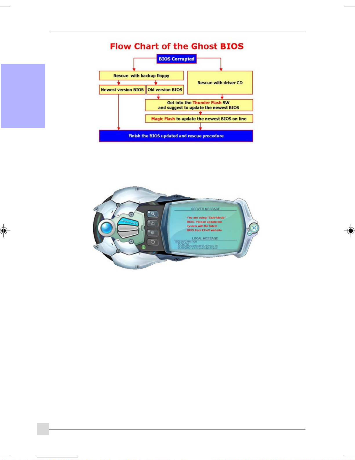
If the screen below is shown, that means your BIOS version is not
updated. Refer to Magic Flash steps to update the BIOS.
20
Page 25

Introduction
Section 6 -- Appendix
6-1 Post Codes6-1 Post Codes
6-1 Post Codes
6-1 Post Codes6-1 Post Codes
POST (hex) DESCRIPTION
CFh Test CMOS R/W functionality.
C0h Early chipset initialization:
- Disable shadow RAM
- Disable L2 cache (socket 7 or below)
- Program basic chipset registers
C1h Detect memory
- Auto-detection of DRAM size, type and ECC.
- Auto-detection of L2 cache (socket 7 or below)
C3h Expand compressed BIOS code to DRAM
C5h Call chipset hook to copy BIOS back to E000 & F000 shadow RAM.
01h Expand the Xgroup codes locating in physical address 1000:0
02h Reserved
03h Initial Superio_Early_Init switch.
04h Reserved
05h 1. Blank out screen
2. Clear CMOS error flag
06h Reserved
07h 1. Clear 8042 interface
2. Initialize 8042 self-test
08h 1. Test special keyboard controller for Winbond 977 series Super I/Ochips.
2. Enable keyboard interface.
09h Reserved
0Ah 1. Disable PS/2 mouse interface (optional).
2. Auto detect ports for keyboard & mouse followed by a port & interface swap
(optional).
3. Reset keyboard for Winbond 977 series Super I/O chips.
0B-0Dh Reserved
0Eh Test F000h segment shadow to see whether it is R/W-able or not. If test fails, keep
beeping the speaker.
0Fh Reserved
10h Auto detect flash type to load appropriate flash R/W codes into the run time area in
F000 for ESCD & DMI support.
11h Reserved
12h Use walking 1’s algorithm to check out interface in CMOS circuitry.
Also set real-time clock power status, and then check for override.
13h Reserved
14h Program chipset default values into chipset. Chipset default values are MODBINable by
OEM customers.
15h Reserved
16h Initial Early_Init_Onboard_Generator switch.
17h Reserved
18h Detect CPU information including brand, SMI type (Cyrix or Intel) and CPU level (586 or
686).
19-1Ah Reserved
1Bh Initial interrupts vector table. If no special specified, all H/W interrupts are directed to
SPURIOUS_INT_HDLR & S/W interrupts to URIOUS_soft_HDLR.
1Ch Reserved
1Dh I nitial EARLY_PM_INIT switch.
1Eh Reserved
1Fh Load keyboard matrix (notebook platform)
20h Reserved
English
21
Page 26

Introduction
21h HPM initialization (notebook platform)
22h Reserved
23h 1. Check validity of RTC value:
e.g. a value of 5Ah is an invalid value for RTC minute.
2. Load CMOS settings into BIOS stack. If CMOS checksum fails, use default value
instead.
English
24-26h Reserved
27h Initialize INT 09 buffer
28h Reserved
29h 1. Program CPU internal MTRR (P6 & PII) for 0-640K memory address.
2A-2Ch Reserved
2Dh 1. Initialize multi-language
2E-32h Reserved
33h Reset keyboard except Winbond 977 series Super I/O chips.
34-3Bh Reserved
3Ch Test 8254
3Dh Reserved
3Eh Test 8259 interrupt mask bits for channel 1.
3Fh Reserved
40h Test 8259 interrupt mask bits for channel 2.
41h Reserved
42h Reserved
43h Test 8259 functionality.
44h Reserved
45-46h Reserved
47h Initialize EISA slot
48h Reserved
49h 1. Calculate total memory by testing the last double word of each 64K page.
4A-4Dh Reserved
4Eh 1. Program MTRR of M1 CPU
4Fh Reserved
50h Initialize USB
51h Reserved
52h Test all memory (clear all extended memory to 0)
53-54h Reserved
55h Display number of processors (multi-processor platform)
56h Reserved
57h 1. Display PnP logo
3. Prepare BIOS resource map for PCI & PnP use. If ESCD is valid,
take into consideration of the ESCD’s legacy information.
4. Onboard clock generator initialization. Disable respective clock
resource to empty PCI & DIMM slots.
5. Early PCI initialization:
-Enumerate PCI bus number
-Assign memory & I/O resource
-Search for a valid VGA device & VGA BIOS, and put it into C000:0.
2. Initialize the APIC for Pentium class CPU.
3. Program early chipset according to CMOS setup. Example: onboard IDE controller.
4. Measure CPU speed.
5. Invoke video BIOS.
2. Put information on screen display, including Award title, CPU type, CPU speed ….
2. Program writes allocation for AMD K5 CPU.
2. Initialize L2 cache for P6 class CPU & program CPU with proper cacheable range.
3. Initialize the APIC for P6 class CPU.
4. On MP platform, adjust the cacheable range to smaller one in case the cacheable
ranges between each CPU are not identical.
2. Early ISA PnP initialization
22
Page 27

Introduction
-Assign CSN to every ISA PnP device.
58h Reserved
59h Initialize the combined Trend Anti-Virus code.
5Ah Reserved
5Bh (Optional Feature) Show message for entering AWDFLASH.EXE from FDD (optional)
5Ch Reserved
5Dh 1. Initialize Init_Onboard_Super_IO switch.
2. Initialize Init_Onbaord_AUDIO switch.
5E-5Fh Reserved
60h Okay to enter Setup utility; i.e. not until this POST stage can users enter the CMOS setup
utility.
61-64h Reserved
65h Initialize PS/2 Mouse
66h Reserved
67h Prepare memory size information for function call: INT 15h ax=E820h
68h Reserved
69h Turn on L2 cache
6Ah Reserved
6Bh Program chipset registers according to items described in Setup & Auto-configuration
table.
6Ch Reserved
6Dh 1. Assign resources to all ISA PnP devices.
2. Auto assign ports to onboard COM ports if the corresponding item in Setup is set to
“AUTO”.
6Eh Reserved
6Fh 1. Initialize floppy controller
2. Set up floppy related fields in 40:hardware.
70-72h Reserved
73h (Optional Feature) Enter AWDFLASH.EXE if :
-AWDFLASH is found in floppy drive.
-ALT+F2 is pressed
74h Reserved
75h Detect & install all IDE devices: HDD, LS120, ZIP, CDROM…..
76h Reserved
77h Detect serial ports & parallel ports.
78h-79h Reserved
7Ah Detect & install co-processor
7B-7Eh Reserved
7Fh 1. Switch back to text mode if full screen logo is supported.
-If errors occur, report errors & wait for keys
-If no errors occur or F1 key is pressed to continue:
Clear EPA or customization logo.
80h-81h Reserved
82h 1. Call chipset power management hook.
2. Recover the text font used by EPA logo (not for full screen logo)
3. If password is set, ask for password.
83h Save all data in stack back to CMOS
84h Initialize ISA PnP boot devices
85h 1. USB final Initialization
2. NET PC: Build SYSID structure
3. Switch screen back to text mode
4. Set up ACPI table at top of memory.
5. Invoke ISA adapter ROMs
6. Assign IRQs to PCI devices
7. Initialize APM
8. Clear noise of IRQs.
86-92h Reserved
English
23
Page 28

Introduction
93h Read HDD boot sector information for Trend Anti-Virus code
94h 1. Enable L2 cache
2. Program boot up speed
3. Chipset final initialization.
4. Power management final initialization
5. Clear screen & display summary table
English
95h 1. Program daylight saving
96h 1. Build MP table
FFh Boot attempt (INT 19h)
6. Program K6 write allocation
7. Program P6 class write combining
2. Update keyboard LED & typematic rate
2. Build & update ESCD
3. Set CMOS century to 20h or 19h
4. Load CMOS time into DOS timer tick
5. Build MSIRQ routing table.
24
Page 29

Abschnitt 1 -- Einführung
1-1 Inhalt des Produktkartons
Introduction
Inhalt
A. Mainboard
B. Benutzerhandbuch
C. Kabel für Diskettenlaufwerk
D. Kabel für Festplatte
E. CD (Treiber und Dienstprogramme)
F. E/A-Abschirmung
G. SATA II-Datenkabel
A
USER’S
MANUAL
B
Optionale Artikel
H. Zusätzliches Kabel für USB 2.0-
Schnittstelle
I. COM-Anschlussblech
J. Druckeranschlussblech
K. Kabel für Thermo-Stick
L. Hinterer E/A-Lüfter
Wenn Sie den optionalen Artikel benötigen,
kontaktieren Sie bitte Ihren Händler.
E
C
D
F
Deutsch
G
Wenn Sie RAID einrichten möchten:
Wenn Sie Windows XP/2000 auf einem RAID-Laufwerk installieren, brauchen Sie eine Diskette mit dem RAID-Treiber,
der vom Betriebssystem benötigt wird. Die folgenden Schritte erklären Ihnen, wie Sie diese Treiberdiskette anlegen:
1. Legen Sie die mitgelieferte CD in das CD-ROM-Laufwerk eines PCs ein.
2. Ein Menübildschirm erscheint (die CD startet automatisch).
3. Wählen Sie die Seite "RAID Floppy".
4. Legen Sie eine leere Diskette in das Laufwerk A: ein.
5. Klicken Sie auf den erforderlichen RAID-Treiber; die nötigen Dateien werden auf die Diskette kopiert.
H
I J
K
L
1
Page 30

Introduction
1-2 Mainboard-Merkmale
Socket AM2
Socket AM2-(940-pol.) basierte Motherboards sind so ausgelegt, dass sie Leistungssteigerungen fur Systeme
auf Basis des AMD Athlon AM2-Prozessors bieten. Zudem wird erwartet, dass sie die Plattform-Innovationen
der nächsten Generation sein werden.
Weitere Informationen über alle neuen Funktionen des Athlon™ AM2-Prozessors finden Sie auf der
AMDWebsite unter
Chipset
Das Mainboard ist mit dem nVidia nForce 570 SLI-Chipset ausgestattet, welches Leistung und Stabilität aufgrund
von innovativster Technologie und Funktionsweise bietet.
Weitere Details über das nVidia-Chipset finden Sie auf der nVidia-Website unter
PCI-Express (PCI-E)
Deutsch
Die Schnittstelle für Peripheriegeräte der nächsten Generation, um den aktuellen PCI-Bus für die nächsten
zehn Jahre abzulösen. Mit einem kleineren Steckplatzformat und einer maximalen Übertragungsrate von 250
MB/s (PCI-E*1) oder 4 GB/s (PCI-E*16) überwindet PCI-Express die PCI-Bus-Engstelle.
NVIDIA SLI
Die NVIDIA SLi
und skalierbares System kombiniert werden! Spieler und unerschütterliche Enthusiasten wissen, dass DualGPUs gesteigerte, turboaufgeladene 3D-Grafiken und Leistung bedeuten.
DDRII
DDRII führt die neue Ära der DDR-Speichertechnologie ein. DDRII-Speicher bieten eine höhere
Geschwindigkeit, eine größere Datenbandbreite und niedrigen Stromverbrauch.y un menor consumo de
alimentacióntion over DDR.
Dual-Kanal
Unterstützt den Dual-Kanal von DDRII-Speicher, um Ihnen zweimal soviel Bandbreite für eine bessere
Systemleistung zu bieten.
Hardware-Überwachung
Mit Hardware-Überwachung können Sie die unterschiedlichen Aspekte des Systembetriebs und-status überwachen.
Dies betrifft CPU-Temperatur, Spannung und Lüftergeschwindigkeit in U/min.
Dual GbE LAN
Zwei Gigabit-LAN-Controller sind integriert. Das Dual-Gigabit-LAN-Set hebt die übliche Bandbreitenschranke
auf und bietet eine Geschwindigkeit von maximal 1000 Mbps zwischen internen und externen Netzwerken.
Serial ATA II
S-ATA II ist die SATA-Schnittstelle der zweiten Generation mit doppelter Übertragungszeit bis 300 MB/s. Sie
unterstützt NCQ für eine schnellere Lesegeschwindigkeit für Ihre Speichergeräte.
SATA RAID
Mittels Unterstützung des NV-Treibers ist die RAID-Funktion auf den SATA II-Schnittstellen, RAID 0, 1, 0+1,
5, JBOD des Chipsets verfügbar.
More S-ATA II (Optional)
Ein zusätzlicher S-ATA II-Controller wird eingebaut, um weitere S-ATA II-Anschlusserweiterungen über
JMB363 von JMicron mit der RAID-Funktion zu ermöglichen.
e-SATA (Optional)
Mit diesem neuen Standard können Sie wie USB-Geräte externe SATA-Geräte an Ihr System anschließen,
ohne vorab das System auszuschalten. Mit einer gegenüber USB 2.0 6fach höheren
Übertragungsgeschwindigkeit, der RAID-Fähigkeit und der Port-Multiplier-Funktion bietet e-SATA eine so
hervorragende Leistung wie noch nie. Diese Funktion ist nur bei S-ATA II-Anschlüssen über den JMB363Controller von JMicron verfügbar.
USB2.0
Ein gebräuchlicher USB-Standard für den Anschluss von Peripheriegeräten mit einer
Übertragungsgeschwindigkeit bis 480 Mbit/s, wobei rückwärtige Kompatibilität mit dem älteren USB 1.1-Gerät
gewahrt bleibt.
8ch
Liefert 8-Kanal-Audio, um Ihnen das Neueste an realistischem Audio aus DVD-Filmen und Spielprogrammen zu
bieten. Perfekt für Ihr Heimkinosystem.
TM
2
Kurze Einführung
http://www.amd.com.
http://www.nVidia.com.
-Technologie revolutioniert die PC-Leistung, indem mehrere PCI Express GPUs in ein einziges
Page 31

Introduction
AMD Cool'n'QuietTM-Technologie
Die AMD Cool'n'Quiet
Weise reduziert sich die Wärmeabgabe und senkt sich die Lüftergeschwindigkeit, so dass Ihr PC weniger
Geräusche erzeugt.
NVIDIA-Firewall (Optional)
Als eine beispiellose Erweiterung im Design von nForce-Produkten bietet sie hohe Leistung & verbesserte
Zuverlässigkeit für PC-Sicherheitlösungen von Benutzern. Ihre Merkmale sind weitaus umfangreicher als viele
alleinstehende Firewalls bieten können!
NVIDIA ActiveArmorTM (Optional)
Steigert die Netzwerksicherheit bei dennoch höchster Systemleistung, indem CPU-intensive
Paketfilteraufgaben in der Hardware herausgeladen werden, so dass Benutzer eine PC-Netzwerkumgebung
erhalten, die nicht nur schnell sondern auch sicher ist.
TM
-Technologie senkt die CPU-Betriebsspannung, wenn das System inaktiv ist. Auf diese
Sondermerkmale
BIOS-Merkmale:
Ghost BIOS
Haben Sie keine Angst mehr vor einem verfälschten BIOS, so dass Ihr System nicht mehr starten kann. Die
BIOS-Datensicherung onboard stellt die BIOS-Hauptdaten mit nur wenigen, einfachen Schritten wieder her.
Thunder Probe
Eine Hardware-Diagnosesoftware zur Überwachung der Spannung, Temperatur und Geschwindigkeit
unterschiedlicher Hardwaregeräte. Hierin enthalten ist auch eine geniale, eingebaute Lüfterkontrollfunktion
namens Smart Fan.
Thunder Flash
Ein Windows-basiertes Innovations-Tool für sichere und einfache BIOS-Rettungsfunktion, BIOS-FlashFunktion und persönlichen Startbildschirm.
Magic Health
Erstellt bei jedem Systemstart einen Bericht über den Hardwarestatus Ihres Systems, um früh Fehler zu
erkennen. Der überwachte Hardwarestatus umfasst die CPU-Temperatur, die CPU-/Speicher-/ChipsetSpannung, die Lüftergeschwindigkeit (in U-min) für den Gehäuselüfter, den CPU-Lüfter & den Netzteillüfter.
EZ-Boot
Drücken Sie einfach "ESC", um Ihr startfähiges Gerät zu wählen. Kein aufwendiges Suchen im BIOS-Menü
mehr, um das Gerät zu ändern und das System neu zu starten.
PowerBIOS
Unterstützt umfassende Overclocking-Einstellungen über das BIOS. Unterschiedliche, einstellbare Funktion
sind Feineinstellung von FSB-/Speicher-/Chipset-Spannung.
Deutsch
H/W-Merkmale:
Post Port
Ein eingebautes LED-Anzeige-Fehlerbehebungsgerät, mit dem Benutzer Probleme beim Systemstart
feststellen können.
QuickSPDIF
Ein integrierter SPDIF-Ausgang für eine schnelle Verbindung mit Mehrkanal-Lautsprechern. Eliminiert nicht nur
ein Kabelgewirr, sondern liefert auch verlustfreies digitales Audio, damit Sie DVD-Filme und Spielprogramme
mit kristallklarem Sound genießen können.
EZ-Button
Eine praktische Einschalttaste onboard, mit der Sie das System müehelos ein-/ausschalten können,
insbesondere während Debug-Vorgängen oder beim Testen des Systems.
LEDION
Die eingebauten LEDs zeigen den Stromversorgungsstatus der CPU, des Chipsatzes und des DRAMs an. Sie
wissen sofort wo Sie nachschauen können, wenn das Starten des Systems fehlschlägt.
Thermo-Stick (Optional)
Flexibler Thermometer, mit dem Sie Temperaturen mit Hilfe von Software messen können. Ideal zur
Überwachung der Temperaturen der Grafikkarte (VGA), des Chipsets oder sogar der Laufwerke.
3
Page 32
Introduction
1-3 Mainboard-Spezifikation
Prozessor
Unterstützt Socket-AM2-(940-pol.) basierten AMD Athlon-AM2 mit 2,0GTs 16x16 Hyper Transport-
Prozessoren
Unterstutzt VMM (Virtualization-Machine-Monitoring)
Chipset
NVIDIA nForce 570 SLI-Chipset
Hauptspeicher
Vier 240-pol. ungepufferte Nicht-ECC DDRII SDRAM DIMM-Steckplätze
Unterstützt einseitige sowie zweiseitige 1,8V DDRII-533/667/800 DIMMs in der Dualkanal-Architektur mit
256MB/512MB/1GB-Modulen
Unterstützt Speichegröße bis 16 GB
Deutsch
Erweiterungsstecklätze
Drei mit PCI V2.3 konforme PCI-Anschlüsse
Zwei mit PCI Express 1.0a konformer PCI-E-Anschlüsse (x1)
Zwei mit PCI Express 1.0a konformer PCI-E-Anschlüsse (x16) zur Unterstützung der SLi-Technologie
USB
Zehn mit USB 2.0 kompatible USB-Anschlüsse vom eingebetten USB-Controller (4 Anschlüsse auf der
Rückseite)
LAN
Zwei Gigabit-Ethernet über integrierte Marvell 88E1116 Gigabit Ethernet PHY
P-ATA IDE
Ein IDE-Schnittstellen (bis zu 2 IDE-Geräte) mit UDMA-33/66/100/133-Unterstützung vom eingebetteten
IDE-Controller
S-ATA RAID
Sechs S-ATA II-Schnittstellen mit einer Bandbreite bis 300 MB/s mit RAID 0, 1, 0+1 ,5
Mehr S-ATA (Optional)
Zwei S-ATA II-Anschlüsse und ein P-ATA-Anschluss über den JMB363 PCI-Express-auf-2S1P-Controller von
JMicron und e-SATA-Unterstützung
E/A
Integrierter EPoX EP1308 LPC-Bus-E/A-Controller
Legacy Peripherie-Schnittstelle für PS/2-Tastatur & -Maus, Diskettenlaufwerk, Parallel, Seriell und IrDA
(V1.0-konform)
Unterstützt Hardware-Überwachung zur Steuerung der Lüftergeschwindigkeit und Erkennung der CPU-
Temperatur
Intelligente Kontrolle der Lüftergeschwindigkeit für CPU-Lüfter (PWM) für ruhigen Betrieb
Audio
8-Kanalaudio vom integrierten Realtek ALC8xx HDA CODEC
- Unterstützt CD-Eingang
- Unterstützt Buchsenerkennung für narrensichere Installation von Audiogeräten
- Konfiguration der Audiobuchsen auf der Rückseite
Buchsenfarbe
Hellblau
Gelbgrün
Pink
Grau
Schwarz
Orange
roloCkcaJenohP lennahc2 lennahc6 lennahc8
eulBthgiLni-eniLni-eniLni-eniL
emiLtuo-eniLtuo-oeretstnorFtuo-oeretstnorF
kniPni-ciMni-ciMni-ciM
yarGtuo-oeretsediS
kcalBtuo-oeretsraeRtuo-oeretsraeR
egnarOrefoowbuS&retneCrefoowbuS&retneC
4
Für 8ch ALC8xx-Konfiguration
2 Kanal
Audioeingang
Audioausgang
Mikrofoneingang
Audioeingang
Stereoausgang Vorderseite
Mikrofoneingang
Stereoausgang Rückseite
Mitte&Subwoofer
6 Kanal
noitarugifnoC058CLAhc8roF
8 Kanal
Audioeingang
Stereoausgang Vorderseite
Mikrofoneingang
Hellblau
Stereoausgang Rückseite
Mitte&Subwoofer
Page 33

Introduction
BIOS
Flash-EEPROM mit Award Plug&Play BIOS
Unterstützt EZ Boot für schnelle Wahl eines startfähigen Geräts
Unterstützt Magic Health für Berichterstellung über den Hardwarestatus des Systems während des
Systemstarts
Unterstützt Ghost BIOS für BIOS-Wiederherstellung
Schnittstellen für Peripheriegeräte
))
) Auf Rückseite
))
PS/2-Tastatur- und -Mausanschlüsse
Ein S/PDIF-Ausgangsbuchse (Koaxial)
Ein S/PDIF-Optischer Ausgangsbuchse
Ein RJ-45-LAN-Anschluss
Vier USB 2.0-Anschlüsse
Sechs Audiobuchsen
))
) Intergrierter Steckeranschluss und Kontaktstift-Header
))
Ein Anschluss für Diskettenlaufwerk
Ein ATA-100/133-IDE-Anschlüsse über nForce 570 SLI von nVidia
Ein ATA-100/133 IDE-Anschluss über JMB363 von JMicron (Optional)
Sechs zusätzliche USB 2.0-Anschlüsse
Ein Anschluss für CD-Eingang
Ein IR-Anschluss
Ein paralleler (Drucker-)Anschluss
Ein serieller (COM1-)Anschluss
Sechs S-ATA II-Anschlüsse über nForce 570 SLI von nVidia
Zwei S-ATA II-Anschlüsse über JMB363 von JMicron (Optional)
Vier Lüfteranschlüsse
Deutsch
Frontleisten-Controller
Unterstützt Reset- & Soft-Off-Schalter
Unterstützt Festplatten-Aktivitäts-LED & Betriebsanzeige (LED)
Unterstützt PC-Lautsprecher
Unterstützt Audioanschluss (Frontleiste)
Sondermerkmale
Unterstützt KBPO-Funktion - Tastatur-Einschaltvorgang, schaltet den Computer über die Tastatur ein
Unterstützt Wake-On-LAN durch PME
Integrierte Post-Port-LED-Anzeige für System-Debug-Vorgänge
PowerBIOS für ausgezeichnete Overclocking-Funktionen:
-Programmierbare FSB-und PCI-E Taktausgangsfrequenz mit 1 MHz Feineinstellung
-Unterstützt BIOS-einstellbaren CPU-Multiplier, FSB-Takt, PCI-E x16-Takt, DIMM-Frequenz
-Unterstützt BIOS-einstellbare CPU-Kernspannung, Chipset-Spannung und DIMM-Spannung
Unterstützt EZ-Button - Eine praktische Einschalttaste onboard, mit der Sie das System müehelos ein-/
ausschalten können
Unterstützt LEDION - integrierte LED-Stromanzeigen für die CPU, das DDR und den Chipsatz
Unterstützt Thermo-Stick-Temperatur (optional)
Unterstützt Ghost BIOS - Rettung, Wiederherstellung des BIOS auf einfache Weise und keine Angst mehr
vor einem verfälschten BIOS.
Leistungsstarke Programme für Windows
Unterstützt Thunder Probe - Eine Hardware-Diagnosesoftware zur Überwachung der Spannung,
Temperatur und Geschwindigkeit unterschiedlicher Hardwaregeräte. Hierin enthalten ist auch eine geniale,
eingebaute Lüfterkontrollfunktion namens Smart Fan.
Unterstützt Thunder Flash - Ein Windows-basiertes Innovations-Tool für sichere und einfache BIOS-
Rettungsfunktion, BIOS-Flash-Funktion und persönlichen Startbildschirm.
Formfaktor
305mm x 245 mm A TX-Größe
5
Page 34
Introduction
Unterstütztes Betriebssystem
Windows 2000, Windows XP
Je nach Modell sind einige Komponenten optional und sind eventuell nicht verfügbar.
1-4 System-Blockdiagramm
Deutsch
6
Page 35
Schalten Sie immer den Computer aus und trennen das Netzkabel vom Netz,
bevor Sie Geräte in den Computer einbauen oder davon entfernen.
2-1 CPU-Installation
Installation
Abschnitt 2 -- Installation
Schritt 1
Heben Sie den Hebel, um den Sockel zu öffnen.
(1)
(2)
Schritt 2
(1) Richten Sie wie abgebildet den Pol 1 der CPU auf den Pol 1 am CPU-
Sockel aus. Stecken Sie die CPU ein. Stellen Sie sicher, dass sie richtig
im Sockel sitzt.
(2) Arretieren Sie die CPU, indem Sie den Hebel nach unten drücken und
einrasten.
Die CPU ist eingekerbt, um eine falsche Installationsrichtung
vorzubeugen. Erzwingen Sie die CPU nicht in den Sockel. Prüfen Sie
die Ausrichtung, wenn sie sich nicht leicht einstecken lässt.
Schritt 3
Installieren Sie wie abgebildet den Kühlkörper. Drücken Sie die
Klammern in die Pfeilrichtung, um diese Einheit an dem CPU-Sockel zu
befestigen.
Schritt 4
Verbinden Sie das CPU-Lüfter-Stromkabel mit dem CPU-Lüfteranschluss
am Mainboard. Die Installation ist damit abgeschlossen.
Deutsch
• Es muss ein von AMD empfohlenes Wärmeleitmaterial und ein
qualifizierter Kühlkörper verwendet werden, um einen CPUSchaden durch Überhitzung zu vermeiden.
• Tragen Sie Wärmeleitmaterial/-Paste auf die CPU.
7
Page 36
Installation
2-2 Jumper-Einstellungen
Deutsch
JCMOS: Jumper zum Löschen der CMOS-Daten
Sind die CMOS-Daten verfälscht oder Sie haben das Supervisor- oder das
User-Kennwort vergessen, löschen Sie die CMOS-Daten, um das System
wieder mit den im ROM BIOS gespeicherten Standardwerten zu
konfigurieren.
Einstellungen:
1-2: Normal (Standard)
2-3: CMOS löschen
Löschen Sie die CMOS-Daten anhand folgender Schritte.
1. Schalten Sie das System aus.
2. Setzen Sie den Jumper für ein paar Sekunden von “1-2” auf die
Position “2-3”.
3. Setzen Sie den Jumper wieder zurück auf die Position “1-2”.
4. Schalten Sie das System ein und halten Sie die <Del>-Taste
gedrückt, um das BIOS-Setup aufzurufen.
8
Page 37
Installation
2-3 Konfiguration des Systemspeichers
Das Mainboard besitzt vier 240-pol. DDRII DIMMs.
• Unterstützt 533/667/800MHz DDRII SDRAM-Module bis 16 GB.
• Unterstützt ungepufferte DIMM-Konfigurationen, die in der JEDEC DDRII DIMM-Spezifikation definiert
sind.
Dual-Kanal-Schnittstelle:
• Der Speicherzugriff über Dual-Kanal steigert die Systemleistung.
• Für einen funktionstüchtigen Dual-Kanal müssen beide Kanäle mit derselben Menge an Speicher,
vorzugsweise vom gleichen Typ, bestückt sein.
• Die vier DIMM-Sockel sind in zwei Farben unterteilt, damit sie die Kanalpaare besser erkennen können
<Abbildung 1>. Jedes Dual-Kanalpaar hat dieselbe Farbe, z.B. DIMM1 und DIMM2. Für eine optimale
Leistung bestücken Sie einfach DIMM-Sockel derselben Farbe.
Dual Channel 1
DIMM 1
DIMM 2
<Abbildung 1>
Dual Channel 2
DIMM 4
Unterstützte Speicherkonfigurationen:
MMID1
)tib-46(
1#MMIDSD/SSSD/SSSD/SSSD/SS
2#MMIDSD/SSSD/SS
3#MMIDSD/SSSD
4#MMIDSD/SSSD/SS
MMID2
)tib-46(
/SSSD/SSSD/SS
MMID2
)tib-821(
MMID4
)tib-821(
* SS: Einseitiges DIMM, DS: Doppelseitiges DIMM
Speicherinstallation :
Richten Sie für eine Installation die Kerbe am DIMM-Modul mit dem Stecker aus.
Drücken Sie das Modul gerade nach unten, siehe Abbildung, bis sich die weißen Klemmen schließen und das
Modul fest im DIMM-Sockel sitzt.
Deutsch
Kerbe
9
Page 38
Installation
2-4 E/A-Schnittstelle Rückseite
Die rückseitige E/A-Leiste für dieses Mainboard ist nachstehend abgebildet. Verwenden Sie beim Einbau des Mainboards
im Computergehäuse die beigelegte E/A-Abschirmung, um diese rückseitige Leiste zu schützen.
S/PDIF-Ausgangsbuchse
(Koaxial)
PS/2
Maus
PS/2
Tastatur
S/PDIF-Optischer
Ausgangsbuchse
Deutsch
2-5 Interne Steckanschlüsse
1 4
11
RJ45
LAN
USB2.0 x 4 Schnittstellen
RJ45
LAN
1
7.1 Audiokanal
10
3
11
6
5
9
7
13
8
14
15
12
1016
3
2
1
Page 39

Steckanschlüsse Abbildungen Beschreibung
Installation
JCPU_FAN
1
JPWR_FAN
JSYS_FAN
JFAN2
FDD
2
IDE1
3
Primäres IDE
IDE2
Sekundäres IDE
(Optional)
Anschlüsse für CPU-/ Netzteil-/ Gehäuse-/ E/A-Lüfter
JCPU_FAN: Schließen Sie den CPU-Lüfter an diesen Stecker
Control
Sense
+12V
Ground
JPWR_FAN: Verwenden Sie diesen Stecker, wenn Sie einen
an.
zusätzlichen Lüfter im System installieren.
JSYS_FAN: Der Gehäuselüfter sorgt für einen angemessenen
Luftstrom durch das Gehäuse, um den CPU vor
Ground
+12V
Sense
JFAN2: Möchten Sie einen hinteren E/A-Lüfter einbauen,
Überhitzung zu schützen.
dann verbinden Sie bitte dessen Stromanschluss
mit diesem Lüfteranschluss.
Anschluss für Diskettenlaufwerk
1
Primärer IDE-Anschluss
1
Anschluss für das IDE-Gerät, d.h. Festplatte und CD-ROMGerät.
Deutsch
Sekundärer IDE-Anschluss
1
Nur mit der Festplatte zu verbinden.
Werden zwei IDE-Laufwerke am selben
Anschluss verwendet, muss eines auf
Master-Modus und das andere auf SlaveModus gesetzt werden. Details hierzu sind
im Handbuch Ihres Laufwerks angegeben.
4
5
6
7
PW1
PW12
CFPA
CD-IN
CUSB3
CUSB4
CUSB5
23
24
3.3V
+12V
+12V
4
3
+12V+12V
GroundGrou nd
2
1
1
11
Front Line-out-R
NC
NC
NC
Key
+5V
CD_IN_Right
CD_Reference
CD_IN_Left
MIC_In
GND
Front Line-out-L
91
10
NC
1
Ground
+5V
+5V
+5V5V SB
-5VPW-OK
GroundGrou nd
Ground+5V
GroundGrou nd
PS-ON+5V
GroundGrou nd
-12V3. 3V
3.3V3.3V
2
PW1: 24-pol. ATX-Netzanschluss
PW12: 4-pol. ATX-12V-Netzanschluss
Die Stecker der Netzkabel sind so ausgelegt, dass sie nur in eine
Richtung angeschlossen werden können.
Die Netzanschlüsse PW1 und PW12 müssen
gleichzeitig verwendet werden.
CFPA: Audioanschluss auf der Frontleiste
Dieser Audiostecker kommt in die Audiobuchsen auf der
Vorderseite. In Ihrem Handbuch sind die Namen der
Kontaktausgange angegeben.
CD-IN: CD Audioeingänge
Über diese Anschlüsse wird Audio vom CD-ROM-Laufwerk, TVTuner oder der MPEG-Karte empfangen.
CUSB3/CUSB4/CUSB5: Sechs USB 2.0-Header
Es befinden sich 6 zusätzliche USB-Anschlüsse onboard auf dem
Mainboard. Zur Verwendung dieser zusätzlichen USB-Anschlüsse
ist eine USB-Halterung erforderlich. Details teilt Ihnen gerne
Ihre Verkaufsstelle mit.
11
Page 40
Installation
Steckanschlüsse Abbildungen Beschreibung
CFP: Anschluss für Gehäuse-Frontleiste
CFP
8
CIR
CIR: IR Anschluss
Anschluss für ein IrDA-Empfangsgerät.
Deutsch
HD_LED
Diese LED zeigt die Festplattenaktivität an.
PWR_LED
Anschluss für die Betriebsanzeige am PC-Gehäuse.
RST
Anschluss für den RESET-Schalter am PC-Gehäus.
PW_ON
nschluss für die Netztaste am PC-Gehäuse, um das System
einzuschalten. Um das System auszuschalten, halten Sie die
Netztaste 4 Sekunden lang gedrückt.
9
10
11
12
CSPK
SATA1
SATA6
SATA7
SATA8
(Optional)
LEDION
LPT1
GND
GND
CSPK: Lautsprecher
Anschluss für den Lautsprecher des Gehäuses, der die PCPieptöne ausgibt.
1
B+
A+
GND
A-B-
GND
1
A+
GND
B+
A-B-
GND
SATA1 ~ SATA6: Sechs S-ATA II Anschlüsse
Diese Anschlüsse erlauben Ihnen Serial ATA-Festplatten oder
optische Laufwerktypen vorgesehen.
SATA7 ~ SATA8: Zwei S-ATA II Anschlüsse
Diese Anschlüsse erlauben Ihnen Serial ATA-Festplatten oder
optische e-SATA-Laufwerke anzuschließen.
LEDION:
Die eingebauten LEDs zeigen den Stromversorgungsstatus der
CPU, des Chipsatzes und des DRAMs an. Sie wissen sofort wo
Sie nachschauen können, wenn das Starten des Systems
fehlschlägt.
LPT1: Paralleler (Drucker-)Anschluss
Der parallele Anschluss kann Drucker und sonstige parallele
Geräte aufnehmen.
THM-ST
13
(Optional)
CP80P
14
EZ-Button
15
12
THM-ST: Thermo Stick
Flexibler Thermometer, mit dem Sie Temperaturen mit Hilfe
von Software messen können. Ideal zur Überwachung der
Temperaturen der Grafikkarte (VGA), des Chipsets oder sogar
der Laufwerke.
CP80P: Post-Port-Debug-LED
Zeigt anhand eines zweistelligen POST-Codes an, warum das
System nicht starten konnte. Ermöglicht eine schnelle und
problemlose Optimierung. Die LED zeigt die CPU-Temperatur
an, wenn Sie die beigelegte Thunder Probe-Software
ausführen.
EZ-Button — RESET, PW-ON:
Diese Tasten onboard dienen zum bequemen Ein-/Ausschalten
des Systems, was besonders praktisch für einen Debug-Vorgang
oder zum Testen des Systems ist.
Page 41

Installation
Steckanschlüsse Abbildungen Beschreibung
RTS
16
COM1
RI
DSR
CTS
TXD
DTR
10
9
Ground
2
1
DCD
RXD
COM1: Serieller Anschluss
Der serielle Anschluss kann Modems, serielle Drucker,
Remote-Anzeigeendgeräte und sonstige serielle Geräte
aufnehmen.
Abschnitt 3 -- BIOS Setup
BIOS Setup
Beim erstmaligen Start Ihres Computers müssen Sie das BIOS CMOS-Setup-Dienstprogramm aufrufen. Schalten Sie
den Computer ein und drücken Sie die <Del>-Taste während des POST-Vorgangs (Einschaltselbsttest). Das
Dienstprogramm BIOS CMOS SETUP UTILITY, siehe unten, öffnet sich:
Deutsch
< CMOS-Setup-Dienstprogramm>
Wählen Sie die Seite "Load Optimized Defaults". um sie aufzurufen. Diese Seite lädt die werkseitigen Einstellungen, die
für eine optimale Systemleistung ausgelegt sind. Stellen Sie diesen Vorgang anhand der einfachen Anweisungen auf
dem Bildschirm fertig. Drücken Sie "ESC", um die Seite zu schließen, und wählen Sie "Save & Exit Setup", um den
Startvorgang fortzusetzen.
Weitere Informationen über die BIOS-Einstellungen sind im ausführlichen Handbuch
auf der beigelegten CD angegeben.
13
Page 42

Installation
Abschnitt 4 -- Treiber & Dienstprogramme
Sobald das Betriebssystem installiert ist, müssen Sie die T reiber für das Mainboar d installieren.
Please Select:
Methode 1
Methode 2
Deutsch
Legen Sie die beigelegte CD in das CD-ROM-Laufwerk, woraufhin der Bildschirm mit dem Hauptmenü erscheint. Im
Hauptmenü sehen Sie Links zu den unterstützten Treibern, Dienstprogrammmen und Software.
Methode 1
Diese Methode installiert alle Treiber automatisch.
Methode 2
Diese Methode installiert ausgewählte Treiber.
Schritt 1 : Klicken Sie auf “nVIDIA nForce Driver”, um den Chipset-Treiber zu installieren.
Auto Installation
Manual Installation
Please install SP1 for Windows XP before installing nForce driver
>> nVIDIA nForce Driver
>> REALTEK High Definition Audio Driver
>> USB 2.0 Driver
>> JMicron PCI Express SATA II and PATA Controller Driver
>> AMD Cool’n’Quiet Processor Driver
Schritt 2 : Klicken Sie auf “REALTEK High Definition Audio Driver”, um den Audiotreiber zu
installieren.
Schritt 3 : Klicken Sie auf “USB 2.0 Driver”, um den USB 2.0-Treiber zu installieren.
Schritt 4 : Klicken Sie auf “JMicron PCI Express SATA II and PATA Controller Driver”, um den
JMicron PCI Express SATA II- und PATA Controller-Treiber zu installieren.
Schritt 5 : Klicken Sie auf “AMD Cool’n’Quiet Processor Driver”, um den Prozessortreiber aus der
AMD-Serie zu installieren.
Die Elemente im Hauptmenü sind je nach Modell unterschiedlich.
Sobald die Treiber erfolgreich installiert wurden, können Sie mit der Installation der beigefügten Dienstprogrammen
fortfahren.
14
Page 43

Installation
Abschnitt 5 -- Ghost BIOS
Ghost BIOS hilft Ihnen das Problem mit einem fehlerhaften BIOS, das normalerweise das System nicht mehr starten
lässt, zu beheben. Ghost BIOS erlaubt Ihnen in eigener Regie das BIOS zu reparieren. Damit umgehen Sie es, dass
Sie das Motherboard zur Reparatur zurückschicken müssen.
VV
orberorber
V
orber
VV
orberorber
1. Installieren Sie das Thunder Flash-Dienstprogramm von der beigefügten CD.
2. Erstellen Sie mit Hilfe dieses Programms eine BIOS-Wiederherstellungsdiskette.
eitung für Ghost BIOS:eitung für Ghost BIOS:
eitung für Ghost BIOS:
eitung für Ghost BIOS:eitung für Ghost BIOS:
“LOAD”
Deutsch
Erstellen einer BIOS-Wiederherstellungsdiskette:
1. Führen Sie das Thunder Flash-Dienstprogramm aus.
2. Stellen Sie eine Verbindung mit dem Internet her.
3. Stecken Sie eine leere Diskette in das Diskettenlaufwerk ein und klicken dann auf "LOAD" .
4. Bewahren Sie die Diskette für einen späteren Gebrauch an einer sicheren Stelle auf.
Wenn das BIOS fehlerhaft ist:Wenn das BIOS fehlerhaft ist:
Wenn das BIOS fehlerhaft ist:
Wenn das BIOS fehlerhaft ist:Wenn das BIOS fehlerhaft ist:
Falls das BIOS fehlerhaft geworden ist, starten Sie das System neu. Ein Fenster wird geöffnet, auf dem Sie wählen
können, ob Sie das BIOS von der zuvor erstellten BIOS-Wieherherstellungsdiskette (BRD, Abk. für BIOS Recovery
Disk) oder von der beigefügten Treiber-CD wiederherstellen möchten.
1. Wählen Sie die Wiederherstellung von der BIOS-Wiederherstellungsdiskette, stecken Ihre zuvor erstellte
Diskette ein und klicken dann auf "1".
2. Wählen Sie die Wiederherstellung von der Motherboard-Treiber-CD, legen die Treiber-CD in das optische
Laufwerk ein und klicken dann auf "2".
Nehmen Sie bitte zur Kenntnis, dass die System-Treiber-CD nur das BIOS im abgesicherten
Modus enthält. Nach der Wiederherstellung sollten Sie gegebenenfalls die Einstellungen im
BIOS erneut anpassen.
15
Page 44

Installation
Deutsch
Wird dieser Bildschirm angezeigt, bedeutet dies, dass Ihre BIOS-Version nicht aktualisert
ist. Aktualisieren Sie das BIOS anhand der Magic Flash-Schritte.
16
Page 45

Capítulo 1 — Instalación
1-1 Contenidos de la caja
Introducción
Contenidos
A . Placa base
B. Manual del usuario
C. Cable de unidad de disco flexible
D. Cable de unidad de disco duro
E. CD (controladores y utilidades)
F. Blindaje de E/S
G. Cable de datos SATA II
A
USER’S
MANUAL
B
Accesorios opcionales
H. Cable de puerto USB2.0 adicional
I. Soporte para puerto COM
J. Soporte para puerto de impresora
K. Cable de Thermo Stick
L. Ventilador de E/S posterior
Si necesita el accesorio opcional,
póngase en contacto con si distribuidor
para obtener ayuda.
E
C
D
F
Español
G
Si pretende configurar RAID:
Cuando instale Windows XP/2000 en cualquier unidad RAID, el programa de instalación del sistema
operativo necesitará un disquete con el controlador RAID. Este procedimiento le muestra cómo
preparar esta unidad de disquete con el controlador.
1 . En su PC inserte el CD incluido en la unidad de CD-ROM
2. Aparecerá una pantalla con el menú principal (función de ejecución automática)
3 . Seleccione la página "RAID floppy" (disquete RAID)
4. Inserte un disquete virgen en la unidad A:
5 . Haga clic en el controlador RAID necesario para iniciar la copia en el disquete
H
I J
K
L
1
Page 46

Introducción
1-2 Funciones de la placa base
Socket AM2
Las placas base Socket AM2 (940 patillas) se diseñan para aprovechar al máximo el rendimiento de los
sistemas basados en procesadores AMD Athlon AM2. En la actualidad representan la próxima generación de
innovación en plataformas.
Para más información acerca de todas las nuevas características que ofrece el Procesador Athlon
consulte la página web de AMD en
Chipset
La placa ha sido diseñada con el conjunto de chips nVidia nForce 570 SLI, que ofrece un alto rendimiento y
estabilidad con las tecnologías y características más innovadoras.
Para más datos acerca del conjunto de chips nVidia, visite la página web de nVidia en
PCI-Express (PCI-E)
Es la nueva generación de interfaces periféricas que sucederá al actual bus PCI durante la próxima década. Con un
menor tamaño de ranura y un ancho de banda de 250MB/seg (PCI-E*1) o 4GB/seg(PCI-E*16) máximo, PCIExpress soluciona el cuello de botella que crea el bus PCI.
Español
2
NVIDIA SLI
La tecnología SLi
GPU PCI Express en un solo sistema ampliable. Los aficionados a los juegos y los desarrolladores de software
saben positivamente que hablar de unidades GPU duales equivale a decir mayor rendimiento y funciones
gráficas 3D más versátiles y potentes.
DDRII
DDRII representa la nueva era de la tecnología de memoria DDR. La memoria DDRII ofrece mayor velocidad, un
mayor ancho de banda de datos y un menor consumo de alimentacióntion over DDR.
Doble canal
Soporta canal doble de memoria DDRII para ofrecerle dos veces el ancho de banda de la memoria para así
conseguir un mayor rendimiento del sistema.
Monitorización de hardware
La función de monitorización de hardware le permite monitorizar varios aspectos del funcionamiento y estado de
su sistema. Entre ellos se incluye la temperatura de la CPU, la tensión y la velocidad del ventilador en RPM.
LAN GbE dual
Integra dos controladores LAN Gigabit. Este conjunto doble de LAN Gigabit rompe la barrera tradicional del
ancho de banda, proporcionando un máximo de 1000 Mbps entre las redes interna y externa.
Serie ATA II
S-ATA II es la segunda generación de interfaz SATA. Consigue doblar la velocidad de transferencia hasta
300MB/seg. Soporta NCQ para ofrecer una mayor velocidad de lectura para sus dispositivos de
almacenamiento.
SATA RAID
Función RAID disponible en los puertos SATA II del conjunto de chips, admite RAID 0, 1, 0+1, 5 y JBOD por
medio del controlador NV.
Más S-ATA II (opcional)
Se agrega un controlador S-ATA II para permitir una expansión con más puertos S-ATA II de la forma
completa JMB363 de JMicron con la función RAID.
e-SATA (opcional)
Con este nuevo estándar, ahora puede conectar en caliente controladores SATA externos al sistema similares
a los dispositivos USB. Con velocidades de transferencia hasta 6 veces superiores a la interfaz USB2.0, la
tecnología RAID y la función Multiplicador de puertos, e-SATA proporciona un rendimiento nunca visto para
almacenar información fuera de la caja. Esta función solamente está disponible en puertos S-ATA II del
controlador JMB363 de JMicron.
USB2.0
Un popular estándar USB para conectar periféricos, que alcanza una velocidad de transferencia de hasta
480Mbps manteniendo la compatibilidad con el antiguo estándar USB1.1.
8 canales
Ofrece 8 canales que le permitirán experimentar el mayor realismo sonoro al ver películas o juegos en DVD.
Perfecto para su sistema de cine en casa.
TM
ha revolucionado el rendimiento de los equipos personales combinando varias unidades
Breve introducción
http://www.amd.com
TM
AM2,
http://www.nVidia.com.
Page 47

Introducción
Tecnología AMD Cool’n’Quiet
La tecnología AMD’s Cool’n’QuietTM reduce la tensión de funcionamiento de la CPU si el sistema se encuentra
en suspensión. Esto permite reducir la disipación de calor y por tanto reducir la velocidad del ventilador y, en
último caso, el ruido que emite su PC.
CORTAFUEGOS NVIDIA (Opcional)
Un diseño sin precedentes para un producto nForce. Ofrece un alto rendimiento y una mayor fiabilidad como
solución de seguridad de PC para los usuarios. ¡Sus características son más avanzadas de lo que muchos
cortafuegos independientes pueden ofrecer!
NVIDIA ActiveArmorTM (Opcional)
Mejora la seguridad de las redes y aumenta su rendimiento, realizando en hardware las tareas de filtrado de
paquetes que más cargan a la CPU, creando un entorno de red rápido y seguro para los usuarios.
TM
Funciones especiales
Funciones BIOS:
Ghost BIOS
Ya no tendrá que preocuparse si su BIOS se corrompe y no puede iniciar el sistema. La función de copia de
seguridad BIOS en placa rescatará y recuperará su BIOS en unos pocos pasos.
Thunder Probe
Un programa de diagnóstico hardware para monitorizar la tensión, temperatura y velocidad de varios
componentes de hardware. También incluye una ingeniosa función de control de ventilador integrada llamada
Smart Fan.
Thunder Flash
Una innovadora herramienta para Windows que permite rescatar de forma segura y sencilla los datos de la
BIOS, grabar la BIOS y personalizar la pantalla de inicio.
Magic Health
Informa acerca del estado del hardware de su sistema después de cada inicio para detectar los fallos antes
de que se produzcan. Monitoriza el estado de su hardware, incluyendo la temperatura de su CPU, la tensión
de la CPU/Memoria/Chipset, la velocidad del ventilador del chasis, de la CPU y de la fuente de alimentación en
RPM.
EZ-Boot
Sólo tiene que presionar “ESC” para seleccionar su dispositivo de inicio. Ya no tendrá que buscar en el menú
de la BIOS, cambiar el dispositivo y reiniciar.
PowerBIOS
Soporta toda la gama de funciones de aceleración por medio de BIOS. Entre las funciones de ajuste se
encuentra el aumento de tensión de FSB/Memoria/Chipset.
Español
Características Hardware:
Post Port
Un dispositivo de resolución de problemas con pantalla LED que facilita al usuario detectar problemas de inicio.
QuickSPDIF
Conector de salida SPDIF para conectar rápidamente altavoces multicanal. No sólo elimina la molestia de
gestionar varios cables sino que ofrece sonido digital sin pérdidas y le permite disfrutar de películas en DVD y
juegos con un sonido claro y cristalino.
EZ-Button
Un botón de encendido localizado en la placa para encender/apagar el sistema fácilmente, especialmente útil
para depurar o probar el sistema.
LEDION
Indicadores LED integrados que muestran el estado de alimentación del procesador, del conjunto de chips y
de la memoria DRAM. Sabrá inmediatamente dónde buscar si el sistema no arranca.
Thermo Stick (Opcional)
Termómetro flexible que le permite medir cualquier temperatura por software. Ideal para monitorizar una
tarjeta VGA, un chipset o incluso la temperatura de unidades de disco.
3
Page 48

Introducción
1-3 Especificación de placa base
Procesador
Admite procesadores Hyper Transport AMD Athlon-AM2 basado en Socket-AM2 (940 patillas) con 2,0GTs
16x16
Admite VMM (Monitorización de virtualización de máquina)
Chipset
Conjunto de chips nVidia nForce 570 SLI
Memoria principal
Cuatro zócalos DIMM SDRAM DDRII no ECC de 240 patillas
Soporta módulos DIMM DDRII-533/667/800 de 1,8 V de una sola cara o de doble cara con arquitectura
dual en las tecnologías de 256 Mb, 512 Mb y 1 Gb
Soporta hasta 16GB de memoria
Ranuras de expansión
Tres conectores PCI compatibles con PCI v2.3
Dos conector PCI-E (x1) compatible con PCI Express 1.0a
Dos conectores PCI-E (x16) compatibles con PCI Express 1.0a que admiten la tecnología SLi
USB
Diez conectores USB compatibles con USB2.0 desde controladores USB integrados (4 conectores
en el panel posterior)
LAN
Dos Gigabit Ethernet de Marvell 88E1116 Gigabit Ethernet PHY integrado
Español
P-ATA IDE
Un interfaces IDE (hasta 2 dispositivos IDE) con UDMA-33/66/100/133 con soporte para controlador IDE
integrado
S-ATA II
Seis puertos S-ATA II con un ancho de banda de hasta 300MB/s con RAID 0, 1, 0+1, 5
Más S-ATA (opcional)
Dos puertos S-ATA II y un puerto P-ATA de PCI-Express JMB363 de JMicron para el controlador 2S1P y
compatibilidad e-SATA.
E/S
Controlador de bus de E/S EPoX EP1308 LPC en placa
Interfaz de periféricos compatibles para ratón y teclado PS/2, FDD, Paralelo, Serie e IrDA (compatible con
v1.0)
Soporte de monitorización hardware para velocidad de ventilador y sensor de temperatura de CPU
Control de velocidad de ventilador inteligente para ventilador de CPU (PWM) silencioso
Sonido
8 canales de audio del CÓDEC compatible con audio de alta definición Realtek ALC8xx integrado
- Soporte CD-In
- Soporte Detección de conector para instalar dispositivos de sonido
- Configuración de conectores de sonido de panel posterior
Color de conector de sonido
Azul claro
eulBthgiLni-eniLni-eniLni-eniL
Verde
emiLtuo-eniLtuo-oeretstnorFtuo-oeretstnorF
Rosa
kniPni-ciMni-ciMni-ciM
Gris
yarGtuo-oeretsediS
Negro
kcalBtuo-oeretsraeRtuo-oeretsraeR
Naranja
egnarOrefoowbuS&retneCrefoowbuS&retneC
Para configuracion de ALC8xx canales
roloCkcaJenohP lennahc2 lennahc6 lennahc8
2 Canales
Entrada de linea
Salida de linea
Entrada de microfono
Entrada de linea
Salida estereo frontal
Entrada de microfono
Salida estereo posterior
Central y subwoofer
6 Canales
noitarugifnoC058CLAhc8roF
8 Canales
Entrada de linea
Salida estereo frontal
Entrada de microfono
Salida estereo lateral
Salida estereo posterior
Central y subwoofer
4
Page 49
Introducción
BIOS
Flash EEPROM con BIOS Award Plug&Play
Soporte EZ Boot para selección rápida de dispositivos
Soporte Magic Health para informe de estado hardware durante inicio de sistema
Soporte Ghost BIOS para Recuperación de BIOS
Interfaces periféricos
))
)
En panel posterior
))
Puertos de teclado y ratón PS/2
Un conector de salida coaxial S/PDIF
Un conector de salida óptica S/PDIF
Un conector LAN RJ45
Cuatro puertos USB2.0
Seis conectores de sonido
))
) Conector en placa y cabecera
))
Un conector de unidad de disco flexible
Un conectores IDE ATA-100/133 de nForce 570 SLI de Nvidia
Un conector IDE ATA-100/133 de JMB363 de JMicron (opcional)
Seis puertos USB2.0 adicionales
Un conector CD-IN
Un conector IR
Un conector paralelo (impresora)
Un conector de puerto serie (COM1)
Seis conectores S-ATA II de nForce 570 SLI de Nvidia
Dos conectores S-ATA II de JMB363 de JMicron (opcional)
Cuatro conectores de ventilador
Controlador de panel frontal
Soporte para conmutador de reinicio y apagado software
Soporta LEDs de disco HDD y Alimentación
Soporte para altavoz PC
Soporta conector de sonido de panel frontal
Funciones especiales
Soporta función KBPO - Encendido por teclado, encienda el ordenador desde el teclado
Soporta Wake-On-LAN por PME
Pantalla LED en placa para depurar el sistema
PowerBIOS para conseguir excelentes funciones de aceleración:
- Salida de Reloj FSB programable con ajuste de 1MHz
- Soporta multiplicador de CPU ajustable en BIOS, reloj FSB, reloj PCI-E x16 y frecuencia DIMM
- Soporta voltaje de núcleo de CPU ajustable en BIOS, voltaje de Chipset y voltaje de DIMM
Soporta EZ-Button - Un útil botón de encendido en placa para encender/apagar el sistema fácilmente
Soporta LEDION - indicador LED de alimentación para el procesador, la memoria DDR y el conjunto de
chips
Soporta Thermo Stick (Opcional)
Soporta Ghost BIOS - Rescate y recupere su BIOS en un sencillo paso y no vuelva a preocupares de que
se corrompa su BIOS.
Español
Potentes utilidades para Windows
Soporta Thunder Probe - Un programa de diagnóstico hardware para monitorizar la tensión, temperatura
y velocidad de varios componentes de hardware. También incluye una ingeniosa función de control de
ventilador integrada llamada Smart Fan.
Soporta Thunder Flash - Una innovadora herramienta para Windows que permite rescatar de forma
segura y sencilla los datos de la BIOS, grabar la BIOS y personalizar la pantalla de inicio.
Factor de forma
ATX tamaño 305mm x 245 mm
5
Page 50
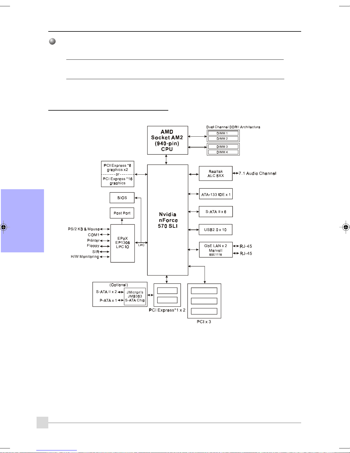
Introducción
Sistemas operativos soportados
Windows 2000, Windows XP
Dependiendo del modelo que haya adquirido, algunos componentes son opcionales
y pueden no estar disponibles.
1-4 Diagrama de bloques del sistema
Español
6
Page 51

Sección 2 — Instalación
Desactive siempre el sistema de alimentación al insertar o retirar
dispositivos del bastidor del ordenador.
2-1 Instalación de procesador
(2)
(1)
Introducción
Paso 1
Abra el zócalo levantando la palanca de actuación.
Paso 2
(1) ) Alinee el contacto 1 del procesador con el contacto 1 del zócalo del
procesador tal y como se muestra. Introduzca el procesador y
asegúrese de que está completamente insertado en el zócalo.
(2) Cierre el zócalo bajando y bloqueando la palanca de actuación.
El procesador tiene un código clave para evitar que se inserte de
forma incorrecta. No fuerce el procesador en el zócalo. Si no entra
fácilmente, compruebe la mala colocación.
Español
Paso 3
Inserte el disipador tal y como se muestra. Presione las abrazaderas en
la dirección de las flechas mostrada para asegurar el montaje al zócalo
del procesador.
Paso 4
Enchufe la alimentación del ventilador del procesador al conector del
ventilador del procesador de la placa base. La instalación ha finalizado.
• El compuesto térmico y el disipador adecuado recomendados por
AMD son indispensables para evitar daños por calentamiento en
el procesador.
• Aplique el compuesto o la pasta térmica del disipador al
procesador.
7
Page 52
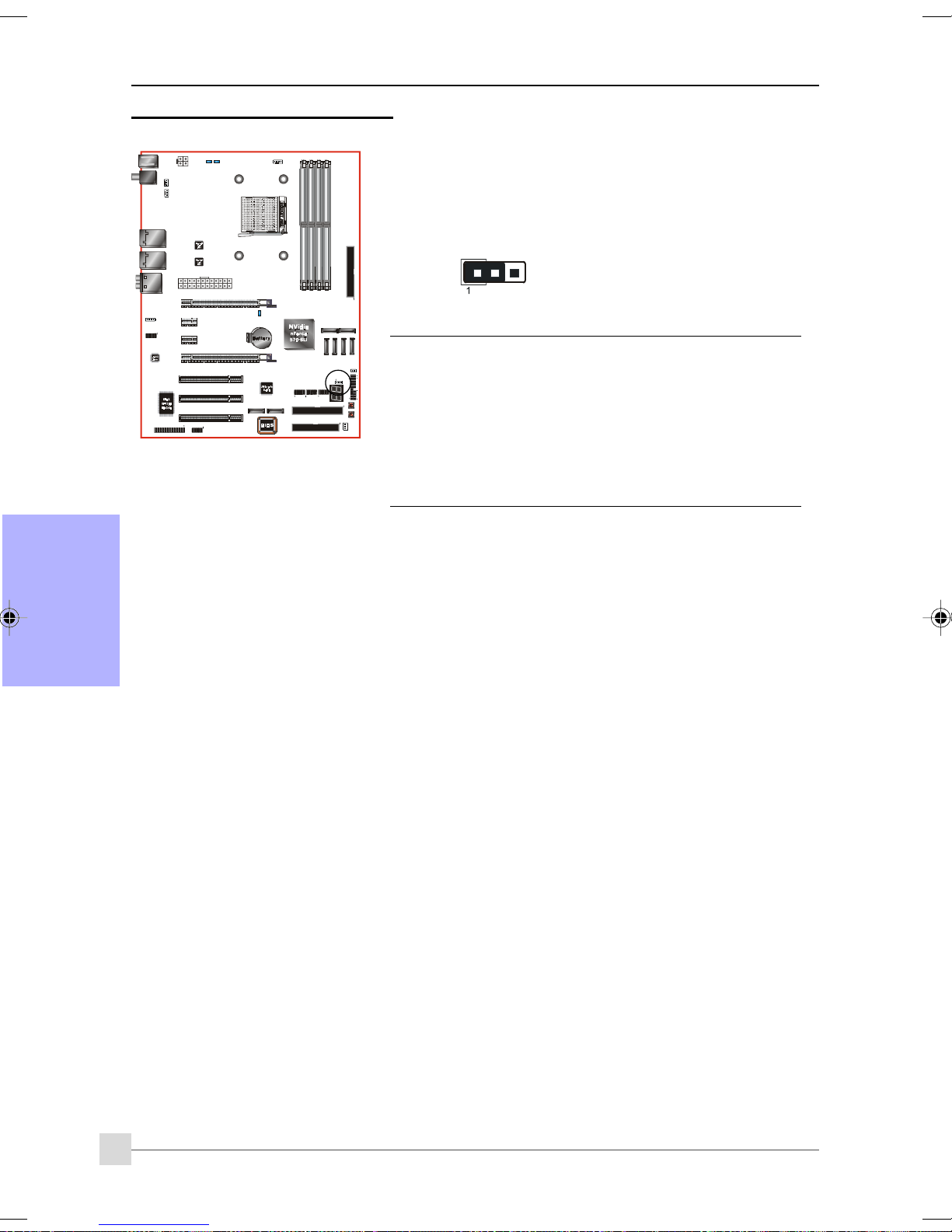
Introducción
2-2 Configuración de puentes
JCMOS: Puente de borrado de datos CMOS
Si se corrompen los datos CMOS u olvida la contraseña de usuario o
supervisor, borre los datos CMOS para volver a configurar el sistema
con los valores predeterminados almacenados en la ROM BIOS.
Configuración:
1-2: Normal (Predeterminado)
2-3: Borrar CMOS
Para borrar los datos CMOS, siga los pasos siguientes.
1. Apague el sistema.
2. Cambie el puente de la posición “1-2” a “2-3” durante
algunos segundos.
3. Coloque de nuevo el puente en la posición “1-2”.
4. Encienda el sistema y mantenga pulsada la tecla <Del>
para entrar en la configuración BIOS.
Español
8
Page 53
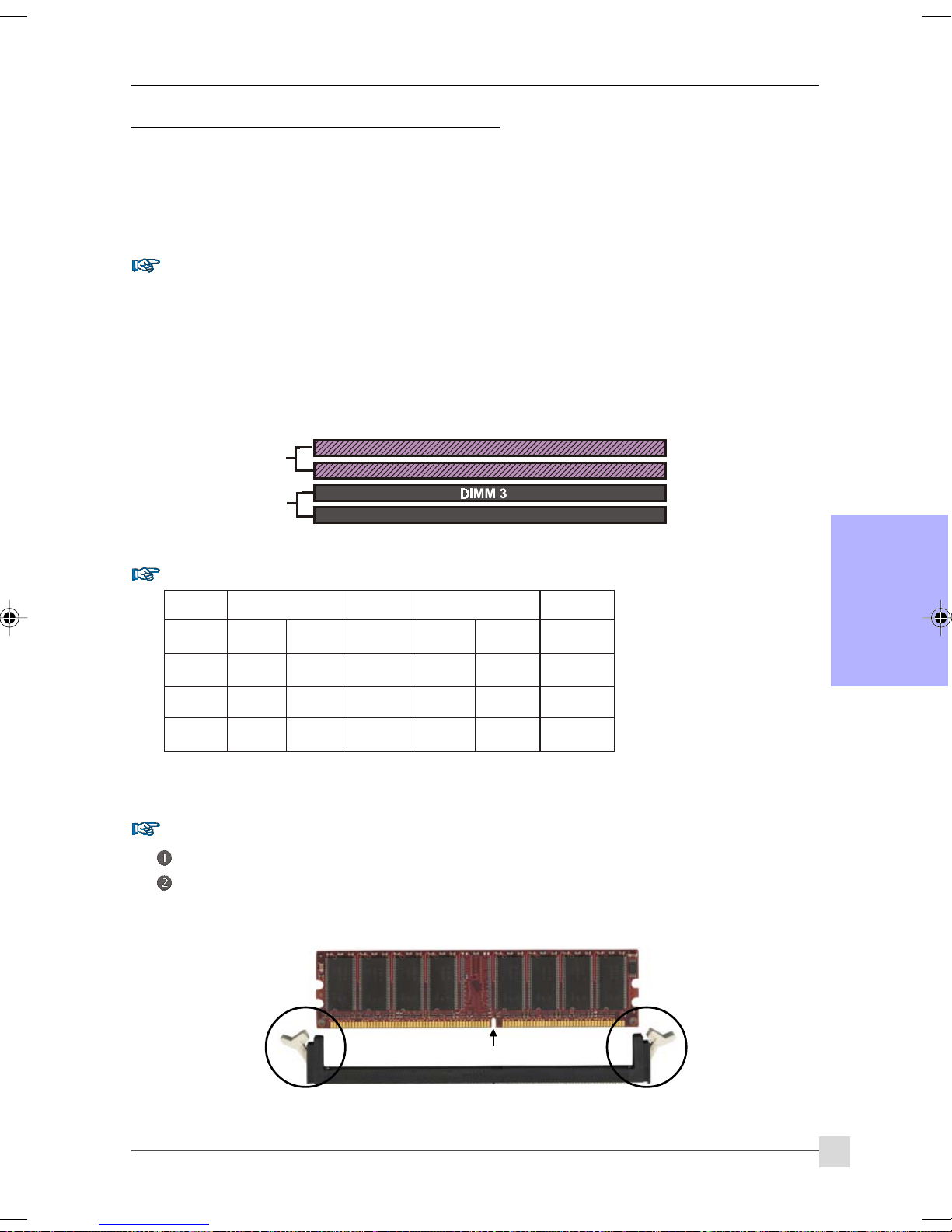
Introducción
2-3 Configuración de memoria de sistema
La placa base puede alojar Cuatro DDRII DIMM de 240 patillas.
• Soporta hasta 16GB de SDRAM DDRII 533/667/800MHz.
• Soporta configuraciones DIMM sin búfer definidas en la especificacione JEDEC DDRII DIMM.
Interfaz de canal doble:
• El acceso doble a memoria de canal ofrece un mayor rendimiento de sistema.
• Para que funcione el canal doble, ambos canales deben tener la misma cantidad de memoria,
preferiblemente del mismo tipo.
• Las cuatro ranuras DIMM se dividen en dos colores para ayudarle a identificar los pares de canales <Figura
1>. Cada par de canales doble tiene el mismo color, por ejemplo el DIMM 1 y el DIMM2. Para conseguir
el mejor rendimiento, monte los DIMM en ranuras del mismo color.
Dual Channel 1
DIMM 1
DIMM 2
<Figura 1>
Dual Channel 2
DIMM 4
Configuraciones de memoria soportadas:
MMID1
)tib-46(
1#MMIDSD/SSSD/SSSD/SSSD/SS
2#MMIDSD/SSSD/SS
3#MMIDSD/SSSD
4#MMIDSD/SSSD/SS
MMID2
)tib-46(
/SSSD/SSSD/SS
MMID2
)tib-821(
MMID4
)tib-821(
* SS: DIMM de una cara, DS: DIMM de doble cara
Instalación de memoria:
Para instalarlo, alinee la muesca del módulo DIMM con el conector.
Presione hacia abajo, como se muestra en la figura, hasta que las pestañas blancas se cierren y el módulo
encaje perfectamente en la ranura DIMM.
Español
Muesca
9
Page 54
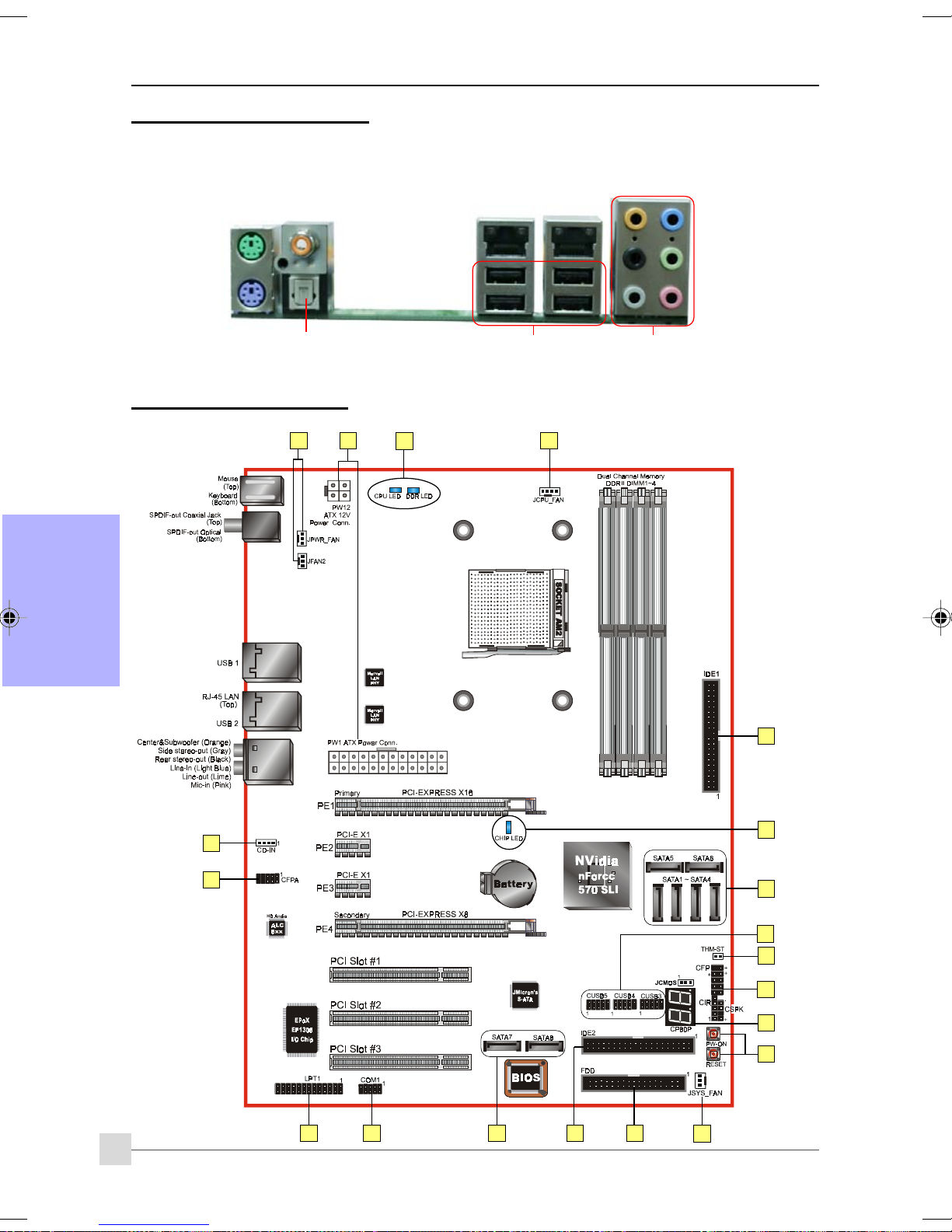
Introducción
2-4 Puerto de E/S posterior
El panel posterior de E/S de esta placa base se muestra a continuación. Para instalar la placa base en la carcasa del
ordenador, utilice el blindaje de E/S suministrado para proteger este panel posterior.
PS/2
Ratón
PS/2
Teclado
2-5 Conectores Internos
Español
Salida S/PDIF
Conector Coaxial
Salida S/PDIF Óptica
1
4
11
RJ45
LAN
Puertos
USB2.0 x 4
RJ45
LAN
7.1 Canales de sonido
1
10
3
11
6
5
9
7
13
8
14
15
12
1016
3
2
1
Page 55

Conector Figura Descripciones
Introducción
JCPU_FAN
1
JPWR_FAN
JSYS_FAN
JFAN2
FDD
2
IDE1
3
IDE Primario
IDE2
IDE Secundario
(Opcional)
Conectores de procesador, alimentación, chasis y
alimentación del ventilador de E/S
Control
Sense
Ground
+12V
JCPU_FAN: Conecte el ventilador de la CPU a este
conector.
JPWR_FAN: Utilice este conector si está instalando un
ventilador adicional en la unidad.
Ground
Sense
+12V
JSYS_FAN: El ventilador del chasis ofrece un flujo de aire
adecuado en todo el chasis para evitar que se
caliente la CPU.
JFAN2: Si instala el ventilador de E/S posterior en la
unidad, enchúfelo a este conector de
ventilador.
1
Conector de unidad de disco flexible
Conector IDE Primario
Conecta un dispositivo IDE, como un disco duro o unidad de
1
CD-ROM.
Conector IDE Secundario
1
Solamente se conecta al dispositivo de la unidad de disco duro.
Si utiliza dos unidades IDE en el mismo
conector, una de ellas debe configurarse en
modo Maestro y la otra en modo Esclavo.
Consulte el manual de usuario de su unidad
de disco para más detalles.
4
5
6
7
PW1
PW12
CFPA
CD-IN
CUSB3
CUSB4
CUSB5
23
3.3V
+12V
+12V
4
3
+12V+12 V
GroundGr ound
2
1
1
Front L ine-out-R
NC
NC
NC
Key
+5V
CD_IN_Right
CD_Reference
CD_IN_Left
MIC_In
GND
Front L ine-out-L
91
10
NC
1
24
Ground
+5V
+5V
+5V5VSB
-5VPW-OK
GroundGround
Ground+5V
GroundGround
PS-ON+5V
GroundGround
-12V3.3V
3.3V3.3V
11
PW1: Conector de alimentación ATX de 24 patillas
PW12: Conector de alimentación ATX12V de 4 patillas
Los conectores de los cables de alimetnación han sido
diseñados para encajar únicamente en una posición.
Los conectores de alimentación PW1 y PW12
deben ser utilizados simultáneamente.
Español
CFPA: Conector de sonido de panel frontal
Este conector de audio se enchufa a las tomas de audio situadas
en el panel frontal. Consulte el manual del dispositivo para hacer
coincidir los nombres de las salidas de los contactos.
2
CD-IN: Conectores de entrada de sonido de CD
Estos conectores se utilizan para recibir sonido desde una unidad
de CD-ROM, sintonizador de TV o tarjeta MPEG.
CUSB3/CUSB4/CUSB5: Cabecera para Seis USB2.0
Estea placa base incluye 6 puertos USB adicionales en placa.
Para utilizar estos puertos adicionales, es necesario utilizar
una placa USB. Póngase en contacto con su distribuidor para
más detalles.
11
Page 56
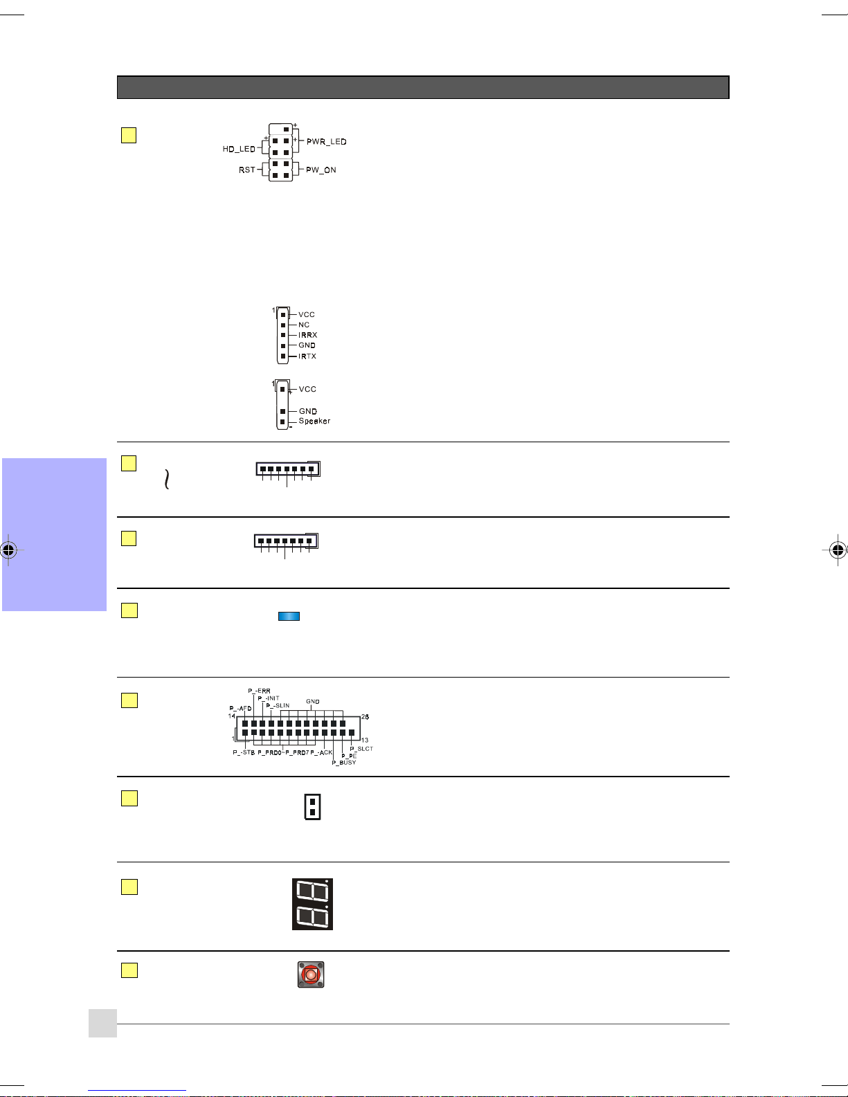
Introducción
Conector Figura Descripciones
CFP: Conector de panel frontal de chasis
CFP
8
HD_LED
Este led indica la actividad del disco duro.
PWR_LED
Conecte este LED al indicador de alimentación del chasis.
RST
Conecte este cable al conmutador RESET del chasis.
PW_ON
Conecte el botón de Encendedido del chasis para
encender el sistema. Para apagar el sistema, mantenga
presionado el botón de encendido durante 4 segundos.
9
Español
10
11
12
CIR
CSPK
SATA1
SATA6
SATA7
SATA8
(Opcional)
LEDION
LPT1
GND
GND
CIR: Conector de IR
Para conectar una unidad receptora de IrDA.
CSPK: Altavoz
Conecte aquí el altavoz del chasis.
1
A+
GND
B+
A-B-
GND
1
A+
GND
B+
A-B-
GND
SATA1 ~ SATA6: Seis conectores SATA II
Estos conectores le permiten conectar discos duros Serie ATA o
unidades ópticas.
SATA7 ~ SATA8: Dos conectores SATA II
Estos conectores permiten conectar unidades de disco duro
Serial ATA o unidades ópticas con e-SATA.
LEDION:
indicadores LED integrados que muestran el estado de
alimentación del procesador, del conjunto de chips y de la
memoria DRAM. Sabrá inmediatamente dónde buscar si el
sistema no arranca.
LPT1: conector de puerto paralelo (impresora)
El puerto paralelo se puede utilizar para impresoras y otros
dispositivos paralelo.
THM-ST
13
(Opcional)
CP80P
14
EZ-Button
15
12
Thermo Stick:
Termómetro flexible que le permite medir cualquier
temperatura por software. Ideal para monitorizar una tarjeta
VGA, un chipset o incluso la temperatura de unidades de
disco.
CP80P: LED de Depuración de puerto post
Ofrece un código POST de dos dígitos que muestra por qué no
se inicia el sistema. Permite una rápida y sencilla optimización.
El LED mostrará la temperatura de la CPU cuando ejecute el
programa Thunder Probe, suministrado.
EZ-Button - RESET, PW-ON:
Estos botones en placa le permiten encender o apagar el
sistema fácilmente. Especialmente indicado para depurar o
comprobar el sistema.
Page 57
Introducción
Conector Figura Descripciones
16
COM1
RI
DSR
CTS
TXD
DTR
10
9
Ground
2
1
DCD
RXD
COM1: conector de puerto serie
El puerto serie se puede utilizar con módems, impresoras
serie, terminales de visualización remotos y otros dispositivos
serie.
RTS
Sección 3 — Configuración BIOS
Configuración BIOS
Al iniciar su ordenador por primera vez, necesitará acceder a la Utilidad de Configuración BIOS CMOS. Encienda el
ordenador y presione la tecla <Del> durante el proceso POST (Prueba automática de arranque). Se mostrará la BIOS
CMOS SETUP UTILITY como en la siguiente ilustración:
< Utilidad de configuración CMOS >
Seleccione y entre en la página “Load Optimized Defaults”. Esta página carga la configuración de fábrica para obtener
un rendimiento óptimo del sistema. Siga sus sencillas instrucciones en pantala para completar este procedimiento.
Presione “ESC” para salir y seleccione “Save & Exit Setup” para reiniciar.
Para más información acerca de la configuración BIOS, consulte el manual completo
en el CD suministrado.
Español
13
Page 58

Introducción
Sección 4 — Controlador y utilidades
Una vez que haya sido instalado el sistema operativo, necesitará instalar los controladores de la placa base.
Please Select:
Método 1
Método 2
Inserte el CD suministrado en la unidad de CD-ROM. Aparecerá la pantalla de menú principal. El menú
principal muestra enlaces a los controladores, utilidades y programas soporteados.
Español
Método 1
Este elemento instala todos los controladores automáticamente.
Método 2
Este elemento le permite instalar los controladores de forma selectiva.
Paso 1: Haga clic en “ nVIDIA nForce Driver” para instalar el controlador de sonido.
Paso 2: Haga clic en “REALTEK High Definition Audio Driver” para instalar el controlador de sonido.
Auto Installation
Manual Installation
Please install SP1 for Windows XP before installing nForce driver
>> nVIDIA nForce Driver
>> REALTEK High Definition Audio Driver
>> USB 2.0 Driver
>> JMicron PCI Express SATA II and PATA Controller Driver
>> AMD Cool’n’Quiet Processor Driver
Paso 3: Haga clic en “USB 2.0 Driver” para instalar el controlador de USB 2.0.
Paso 4: Haga clic en “ JMicron PCI Express SATA II and PATA Controller Driver” para instalar el
controlador de JMicron PCI Express SATA II y PATA.
Paso 5: Haga clic en “AMD Cool’n’Quiet Processor Driver” para instalar el controlador de procesadores
de la gama AMD.
Los elementos del menú principal podrían variar dependiend del
modelo adquirido.
Una vez instalados correctamente el controlador, puede proceder a la instalación el programa de utilidades
incluido.
14
Page 59

Introducción
Sección 5 — Ghost BIOS
Ghost BIOS le permite recuperar una BIOS dañada, que normalmente impediría iniciar su sistema. Ghost BIOS le
permite reparar la BIOS usted mismo, eliminando el problema de devolver la placa base para su reparación.
Preparación para Ghost BIOS:Preparación para Ghost BIOS:
Preparación para Ghost BIOS:
Preparación para Ghost BIOS:Preparación para Ghost BIOS:
1. Instalar la utilidad Thunder Flash que se encuentra en el CD.
2. Crear un Disco de Recuperación de BIOS (BRD) utilizando esta utilidad.
“LOAD”
Crear un Disco de Recuperación de BIOS:
1. Ejecute la utilidad Thunder Flash.
2. Conéctese a Internet.
3. Inserte un disco flexible vacío en la unidad de disco y haga clic en "LOAD".
4. Conserve este disco flexible en un lugar seguro para uso futuro.
Si la BIOS resulta dañada:Si la BIOS resulta dañada:
Si la BIOS resulta dañada:
Si la BIOS resulta dañada:Si la BIOS resulta dañada:
Si la BIOS está corrupta o falla, reinicie el sistema. Aparecerá esta pantalla. Puede elegir entre recuperar la BIOS
desde el disco BRD creado anteriormente o desde el CD de controladores.
1. Seleccione si desea recuperar desde un disco de copia de seguridad de BIOS, inserte el disco flexible y
haga clic en "1".
2. Seleccione si desea recuperar desde el CD de controladores del sistema de placa base, inserte el CD en
la unidad óptica y haga clic en "2".
Español
Recuerde que el CD de controladores se compone únicamente de BIOS de Modo Seguro.
La BIOS debe ser actualizada después de ser recuperada.
15
Page 60

Introducción
Si se muestra esta pantalla, significará que su versión de BIOS no está actualizada.
Consulte los pasos de Magic Flash para actualizar la BIOS.
Español
16
Page 61

1-1 Contenu du paquet
Introduction
Section 1 — Introduction
Table des matières
A . Carte-mère
B. Manuel de l’utilisateur
C. Câble pour lecteur de disquettes
D. Câble pour disque dur
E. CD (pilotes et utilitaires)
F Plaque E/S
G Câble données SATA II
A
USER’S
MANUAL
B
Accessoires optionnels
H. Câble pour port USB2.0 supplémentaire
I. Console de port COM
J. Console de port d'imprimante
K. Câble Thermo Stick
L. Ventilateur à E /S à l'arrière
Si vous voulez acquérir un élément
optionnel, veuillez demander de l’aide à
votre distributeur.
E
C
D
F
G
Si vous avez l'intention d'installer RAID:
Lors de l'installation de Windows XP/2000 dans n'importe quel lecteur RAID, la configuration du S/E requiert une
disquette contenant le pilote RAID. Cette étape vous montrera comment préparer cette disquette.
1. Localiser un PC et insérez le CD groupé dans son lecteur de CD-ROM
2. L'écran du menu principal apparaîtra (fonctionnalité Autorun)
3. Sélectionnez la page de disquette RAID
4. Insérez une disquette vierge dans le lecteur A:
5. Cliquez sur le contrôleur du pilote RAID requis pour commencer à le copier sur la disquette
H
I J
K
L
Français
1
Page 62

Introduction
1-2 Caractéristiques de la carte-mère
Socket AM2
Les cartes-mères sur base Socket AM2 (940 broches) ont été conçues de façon à profiter pleinement des
améliorations des performances des systèmes à processeurs AMD Athlon AM2, et de façon à constituer une
plate-forme de nouvelle génération pour les innovations futures.
Pour de plus amples informations concernant les processeurs Athlon™ AM2, veuillez visiter le site AMD sur
http://www.amd.com.
Chipset
La carte a été conçue avec le chipset nVidia nForce 570 SLI, qui garantit performances et stabilité avec la
technologie et les fonctions les plus innovantes.
Pour plus détails concernant le chipset nVidia, veuillez visiter le site web nVidia sur
PCI-Express (PCI-E)
Interface périphérique de nouvelle génération pour adapter le bus PCI courant à la prochaine génération. Avec
une taille de slot plus petite et des transferts maximum de 250 Mo/sec (PCI-E*1) ou 4 Go/sec(PCI-E*16), PCIExpress aide à résoudre les problèmes d’engorgement du bus PCI.
NVIDIA SLI
La technologie NVIDIA SLi
système extensible ! Les joueurs et les passionnés de cœur matériel savent que les GPU duels signifient des
graphiques 3D super chargés et une performance accrue.
DDRII
Les ushers DDRII dans la nouvelle ère de la technologie de mémoires DDR. Les mémoires DDRII offrent de
plus grandes vitesses, une bande passante plus étendue et une consommation électrique réduite.
Double canal
Prise en charge des canaux doubles de mémoire DDRII afin d’avoir le double de bande passante mémoire pour
de meilleures performances système.
Contrôle du matériel
Le contrôle du matériel vous permet de contrôler différents aspects de l’état et du fonctionnement du système.
Cela comprend la température du processeur, la tension et la vitesse du ventilateur en tours par minute.
LAN GbE duel
Français
Deux contrôleurs Gigabit LAN intégrés. Cette paire identique de Gigabit LAN dépasse la barrière de largeur de
bande traditionnelle, livrant un maximum de 1000 Mbps entre un réseau interne et externe
S-ATA II
S-ATA II est la seconde génération d’interface SATA ; elle double la vitesse de transfert qui atteint les 300
Mo/sec. Elle prend en charge le NCQ pour permettre une lecture plus rapide des périphériques de stockage.
SATA RAID
Fonction RAID disponible sur les ports SA TA II du chipset, prise en charge RAID 0, 1, 0+1, 5, JBOD par pilote NV.
Plus de S-ATA II (En option)
Un contrôleur S-ATA II supplémentaire est ajouté pour permettre plus d'extension de ports S-ATA II dans la
forme de JMB363 de JMicron complet avec fonction RAID.
e-SATA (En option)
Avec cette nouvelle norme, vous pouvez brancher à chaud des lecteurs SATA externes à votre système
identique aux périphériques USB. Avec une vitesse de transfert jusqu'à 6 fois plus rapide que la capacité
USB2.0, RAID et la fonction de multiplicateurs de port, e-SATA offre une performance encore jamais vue au
stockage prêt à utiliser. Cette fonction est disponible uniquement sur les ports S-ATA II de contrôleur JMB363
de JMicron.
USB2.0
Norme USB populaire pour le branchement des périphériques avec une vitesse de transfert maximum de
480Mbps avec rétrocompatibilité avec les anciens périphériques USB1.1.
8ch
Apporte une audio 8 voies pour que vous ayez accès au réalisme audio de dernière génération pour les jeux
et films DVD. L’idéal pour votre système de home cinéma.
TM
révolutionne la performance PC en combinant des GPU PCI Express dans un seul
2
Brève présentation
http://www.nvidia.com.
Page 63

Introduction
Technologie AMD Cool’n’Quiet
La technologie Cool’n’QuietTM d’AMD permet d’abaisser la tension de fonctionnement du processeur lorsque le
système est en mode attente. Cela aide à réduire la dissipation thermique et de réduire efficacement la vitesse
de rotation du processeur et donc le bruit produit par le PC.
Pare-feu NVIDIA (En option)
Une addition nouvelle pour les produits nForce, apporte des performances supérieures et une plus grande
fiabilité de solution de sécurité PC aux utilisateurs. Les fonctions sont plus évoluées que celles que de
nombreux pare-feux autonomes sont capables d’offrir.
NVIDIA ActiveArmor
Permet d’améliorer la sécurité des réseaux tout en optimisant les performances système en déchargeant sur
le matériel les tâches de filtrage des paquets qui recourent au processeur, ce qui apporte aux utilisateurs un
environnement PC à la fois sécurisé et rapide.
TM
(En option)
TM
Fonctions spéciales
Fonctions BIOS :
Ghost BIOS
Plus d’inquiétude en cas de corruption du BIOS empêchant le démarrage de votre système. Le BIOS de
sauvegarde sur carte permet de récupérer le BIOS principal en seulement quelques étapes simples.
Thunder Probe
Logiciel de diagnostic du matériel pour contrôler la tension, la température et la vitesse de divers éléments
matériels. Comprend aussi une très ingénieuse fonction intégrée de contrôle de ventilateur appelée Smart Fan.
Thunder Flash
Outil innovant de base Windows apportant une fonction de récupératiion du BIOS sûre et facile, une fonction
de flashage du BIOS, et un écran de démarrage personnalisé.
Magic Health
Donne un compte-rendu de l’état matériel du système à chaque démarrage afin de vous aider à détecter assez
tôt les défaillances. Contrôle des éléments matériels dont T empér ature processeur, T ension ékectrique processeur/
mémoire/chipset, vitesse de rotation du ventilateur pour le ventilateur du châssis, le ventilateur du processeur
et le ventilateur de l’unité d’alimentation électrique.
EZ-Boot
Il suffit d’appuyer sur “ESC” pour sélectionner votre périphérique d’amorçage. Plus besoin de chercher dans le
menu du BIOS, de modifier et de redémarrer.
PowerBIOS
Prise en charge de toute une gamme de paramètres d’overclocking via le BIOS. Diverses fonctions de réglage
dont réglage tension FSB/Mémoire/Chipset.
Fonctions matérielles :
Port Post
Périphérique de dépannage à indicateurs lumineux sur carte, aide l’utilisateur à détecter les problèmes au
démarrage.
QuickSPDIF
Connecteur de sortie SPDIF sur carte pour connexion rapide de haut-parleurs multivoies. Non seulement
permet de supprimer l’encombrement des câbles, mais aussi apporte une audio numérique sans déperdition
pour vous permettre de profiter de vos jeux et de vos films DVD avec un son d’une clarté cristalline.
EZ-Button
Bouton d’alimentation très pratique placé sur la carte pour allumer et éteindre facilement le système, en
particulier lors des opérations de débogage ou de test du système.
LEDION
Les indicateurs DEL intégrés indiquent le statut d'alimentation de l'UC, du chipset et de la DRAM. Vous savez
immédiatement où chercher si le système ne démarre pas.
Thermo Stick (En option)
Thermomètre souple qui vous permet de mesurer toute température par le biais d’un logiciel. Idéal pour
surveiller les températures de la carte VGA, du chipset ou même des disques durs.
Français
3
Page 64

Introduction
1-3 Spécifications de la carte-mère
Processeur
Prise en charge des processeur Hyper Transport AMD Athlon-AM2 with 2,0GTs 16x16 de base Socket-
AM2 (940 broches)
Prise en charge VMM (Virtualization-Machine-Monitoring)
Chipset
Chipset nVidia nForce 570 SLI
Mémoire principale
Quatre supports non-ECC DIMM DDRII SDRAM sans tampon de 240 broches
Prise en charge de DIMM DDRII-533/667/800 de 1,8 V une face ou double face à double voie
architecture dans des technologies 256Mo/512Mo/1Go
Prise en charge de 16 Go de mémoire maximum
Emplacements d’extension
Trois connecteurs PCI compatibles PCI v2.3
Deux connecteur PCI-E (x1) compatible PCI Express 1.0a
Deux connecteurs PCI-E (x16) compatible PCI Express 1.0a pour prendre en charge la technologie SLi
USB
Dix connecteurs USB compatibles USB2.0 à partir du contrôleur USB incorporé (4 connecteurs sur le panneau
arrière)
LAN
Deux Gigabit Ethernet du Marvell 88E1116 Gigabit Ethernet PHY intégré
P-ATA IDE
Un interfaces IDE (jusqu’à 2 périphériques IDE) avec prise en charge UDMA-33/66/100/133 à partir du
contrôleur IDE incorporé
S-ATA RAID
Quatre ports S-ATA II avec bande passante de 300 Mo/s maximum avec RAID 0, 1, 0+1, 5
Plus de S-ATA (En option)
Deux ports S-ATA II et un port P-ATA du JMB363 PCI-Express de JMicron au contrôleur 2S1P et prise en
Français
E/S
Contrôleur E/S bus EPoX EP1308 LPC sur carte
Interface périphériques anciens pour souris et clavier PS/2, lecteur de disquettes, Parallèle, Série et IrDA
Prise en charge de la surveillance matérielle pour surveillance de la vitesse de ventilateur et détecteur de
Contrôle intelligent de la vitesse ventilateur pour ventilateur du processeur (PWM) pour fonctionnement
Audio
Audio à 8 voies du CODEC conforme à l'audio haute définition Realtek ALC8xx
charge e-SATA.
(compatible v1.0)
la température du processeur
silencieux
- Prise en charge CD-In
- Prise en charge Détection de prise pour l’installation sans problème des périphériques audio
- Configuration des prises audio du panneau arrière
Couleur prise téléphone
Bleu clair
eulBthgiLni-eniLni-eniLni-eniL
Citron
emiLtuo-eniLtuo-oeretstnorFtuo-oeretstnorF
Rose
kniPni-ciMni-ciMni-ciM
Gris
yarGtuo-oeretsediS
Noir
kcalBtuo-oeretsraeRtuo-oeretsraeR
Orange
egnarOrefoowbuS&retneCrefoowbuS&retneC
Pour configuration ALC8xx 8 voies
roloCkcaJenohP lennahc2 lennahc6 lennahc8
2 voies
Entrée de ligne
Sortie de ligne
Entrée micro
Entrée de ligne
Sortie de ligne
Entrée micro
Sortie stéréo arrière
Centre et subwoofer
6 voies
noitarugifnoC058CLAhc8roF
8 voies
Entrée de ligne
Sortie de ligne
Entrée micro
Sortie stéréo latérale
Sortie stéréo arrière
Centre et subwoofer
4
Page 65

Introduction
BIOS
Flash EEPROM avec BIOS Award Plug&Play
Prise en charge EZ Boot pour sélection rapide du périphérique d’amorçage
Prise en charge Magic Health pour compte-rendu de l’état des éléments matériels du système pendant
l’amorçage
Prise en charge Ghost BIOS pour récupération du BIOS
Interfaces périphériques
))
) Sur le panneau arrière
))
Ports souris et clavier PS/2
Un prise coaxiale pour sortie S/PDIF
Un prise optique pour sortie S/PDIF
Un connecteur LAN RJ45
Quatre ports USB2.0
Six prises audio
))
) Barrettes pin et connecteurs sur carte
))
Un connecteur lecteur de disquettes
Un connecteur IDE ATA-100/133 du nForce 570 SLI de nVidia
Un connecteur IDE ATA-100/133 du JMB363 de JMicron (En option)
Six ports USB2.0 supplémentaires
Connecteur CD-IN
Un connecteur IR
Un connecteur parallèle (imprimante)
Un connecteur de port série (COM1)
Six connecteurs S-ATA II du nForce 570 SLI de nVidia
Deux connecteurs S-ATA II du JMB363 de JMicron (En option)
Quatre connecteurs ventilateur
Contrôleur panneau avant
Prend en charge les interrupteurs réinitialisation et arrêt logiciel
Prise en charge indicateurs disque dur et alimentation
Prise en charge haut-parleur PC
Prise en charge connecteur audio de panneau avant
Fonctions spéciales
Prise en charge fonction KBPO – Alimentation clavier, pour mettre l’ordinateur sous tension à partir du
clavier
Prise en charge Wake-On-LAN par PME
Affichage DEL port Post sur carte pour débogage du système
PowerBIOS pour excellentes fonctions d’overclocking :
- Fréquence de sortie horloge FSB et fréquence de sortie Horloge PCI-E programmable par pas de 1MHz
- Prise en charge multiplicateur de processeur réglable par BIOS, horloge FSB, horloge PCI-E x16,
fréquence DIMM
- Prise en charge tension tore processeur réglable par BIOS, tension Chipset et tension DIMM
Prise en charge EZ-Button – Bouton d’alimentation sur carte très pratique permettant d’allumer ou
d’éteindre le système facilement
Prise en charge LEDION - indicateurs DEL intégrés pour l'UC, la DDR et le chipset.
Prise en charge température Thermo Stick (En option)
Prise en charge Ghost BIOS - Secours et récupération du BIOS en une étape facile, plus d’inquiétude
concernant l’endommagement du BIOS.
Puissants utilitaires pour Windows
Prise en charge Thunder Probe - Logiciel de diagnostic du matériel pour contrôler la tension, la
température et la vitesse de divers éléments matériels. Comprend aussi une très ingénieuse fonction
intégrée de contrôle de ventilateur appelée Smart Fan.
Prise en charge Thunder Flash - Outil innovant de base Windows apportant une fonction de
récupératiion du BIOS sûre et facile, une fonction de flashage du BIOS, et un écran de démarrage
personnalisé.
Facteur de forme
F ormat A TX 305mm x 245 mm
Français
5
Page 66

Introduction
Système d'exploitation supporté
Windows 2000, Windows XP
Selon le modèle que vous achetez, il se peut que certains éléments soient en
option ou non disponibles.
1-4 Diagramme bloc système
Français
6
Page 67
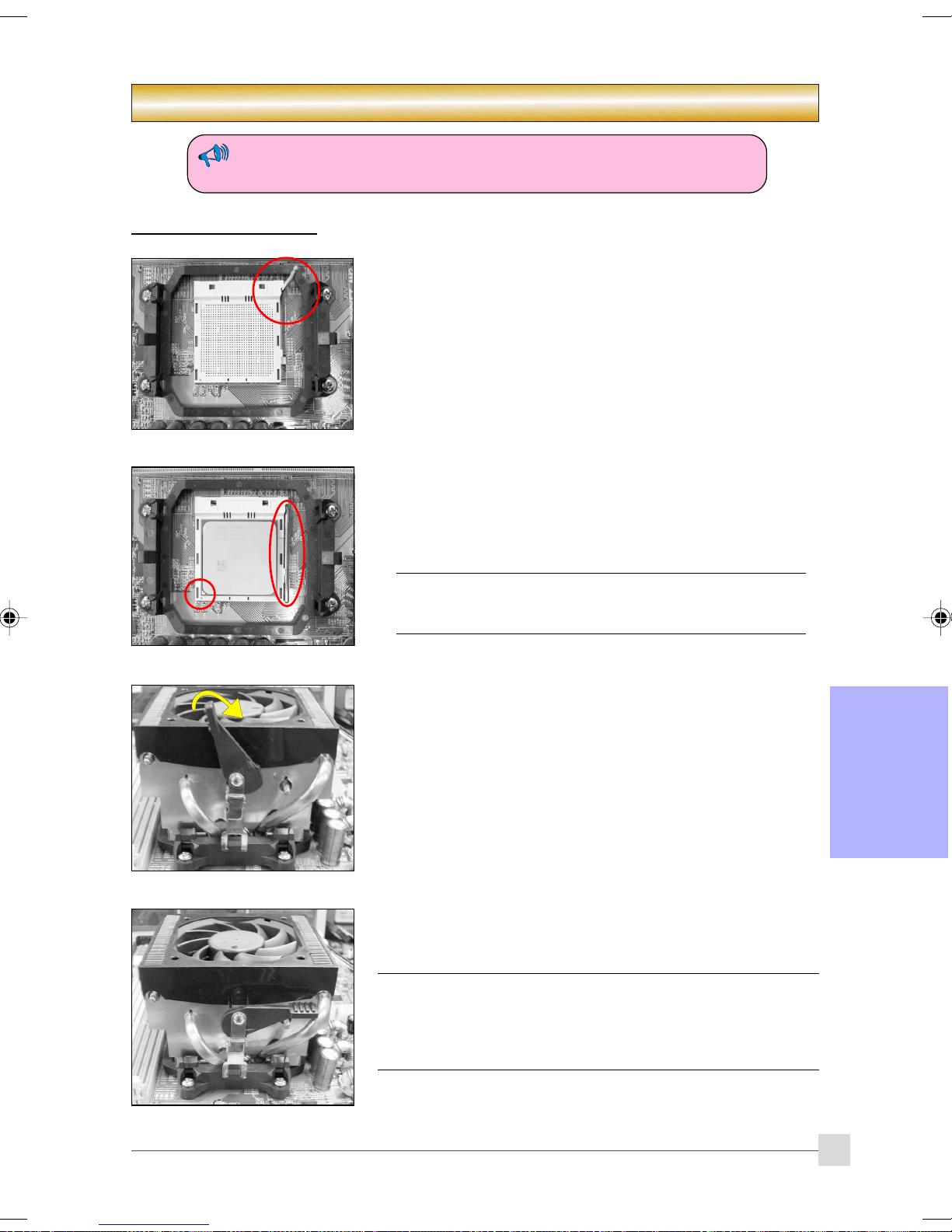
Veillez à ce que l'alimentation soit coupée et débranchée lorsque vous insérez
ou retirez des éléments à l'intérieur du châssis de l'ordinateur.
2-1 Installation du CPU
(2)
(1)
Section 2 — Installation
Etape 1
Ouvrez le support en soulevant le levier.
Etape 2
(1) Alignez la broche 1 sur le CPU avec la broche 1 sur le support de l'US
comme illustré. Insérez le CPU et assurez-vous qu'il est entièrement
inséré dans le support.
(2) Fermez le support en abaissant et verrouillant le levier.
Le CPU est adapté pour empêcher une insertion incorrecte, ne
le forcez pas dans le support. S'il ne s'insère pas facilement,
vérifiez la mauvaise orientation.
Installation
Etape 3
Insérez le dissipateur thermique comme illustré. Appuyez sur les attaches
dans le sens des flèches illustrées afin de sécuriser l'assemblage au
support du CPU.
Etape 4
Branchez l'alimentation du ventilateur du CPU dans le connecteur du
ventilateur du CPU de la carte mère. L'installation est terminée.
• Le composé thermique et le dissipateur de chaleur adéquate
recommandés par AMD sont indispensables pour éviter les
dommages de surchauffe du CPU.
• Appliquez la pâte/composé thermique de dissipateur de chaleur au
CPU.
Français
7
Page 68
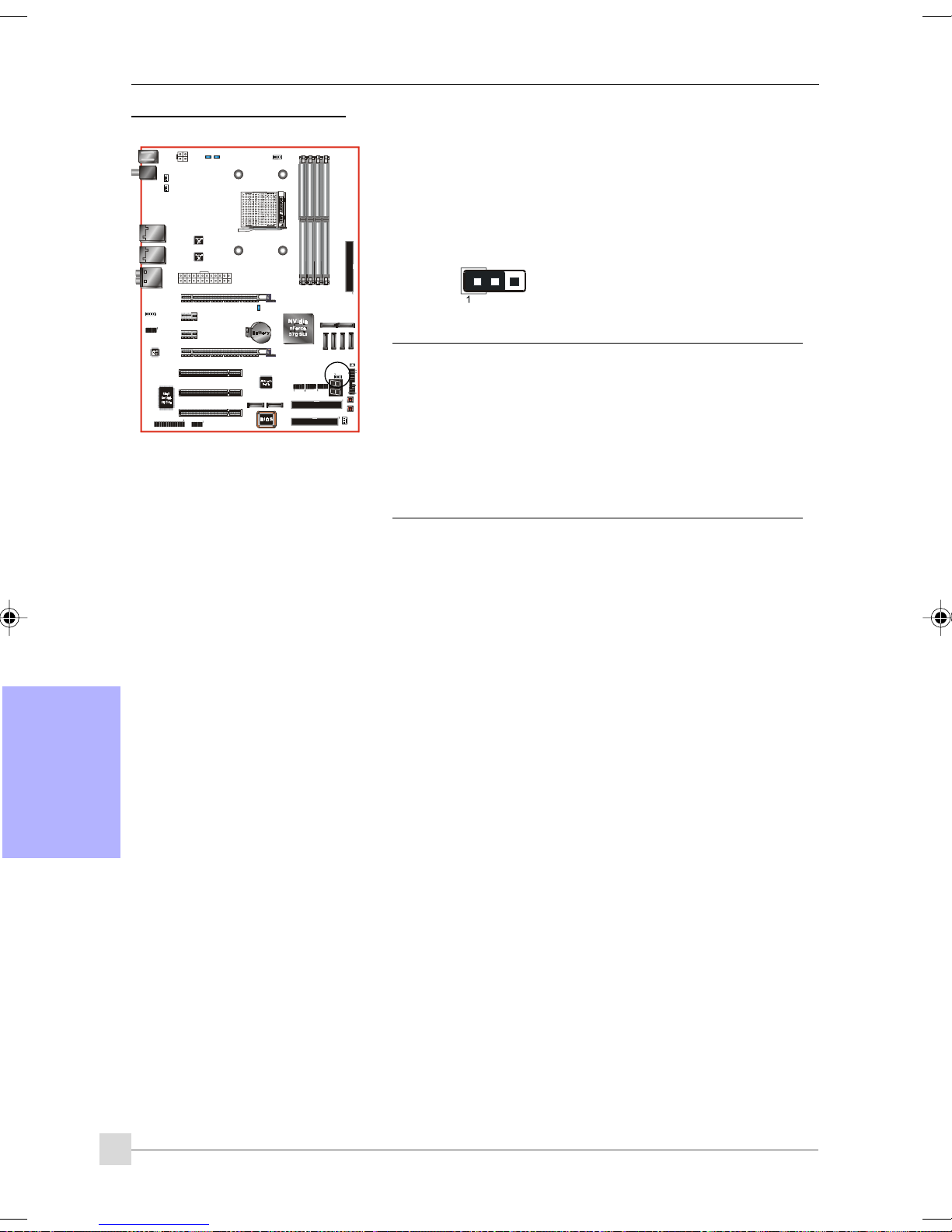
Installation
2-2 Réglages des cavaliers
JCMOS: Cavalier d’effacement des données de la CMOS
Si les données de la CMOS sont endommagées ou si vous avez oublié le
mot de passe superviseur ou utilisateur, effacez les données de la
CMOS pour redonner au système ses valeurs par défaut stockées dans
la ROM BIOS.
Réglages :
1-2 : Normal (Défaut)
2-3 : Effacer la CMOS
Pour effacer les données de la CMOS, veuillez procéder la
façon expliquée ci-dessous.
1. Mettez le système hors tension.
2. Déplacez le cavalier de la position “1-2” sur la position “2-3”
pendant quelques secondes.
3. Remettez le cavalier en place sur la position “1-2”.
4. Mettez le système sous tension et maintenez la touche
<Del> enfoncée pour accéder au setup BIOS.
Français
8
Page 69
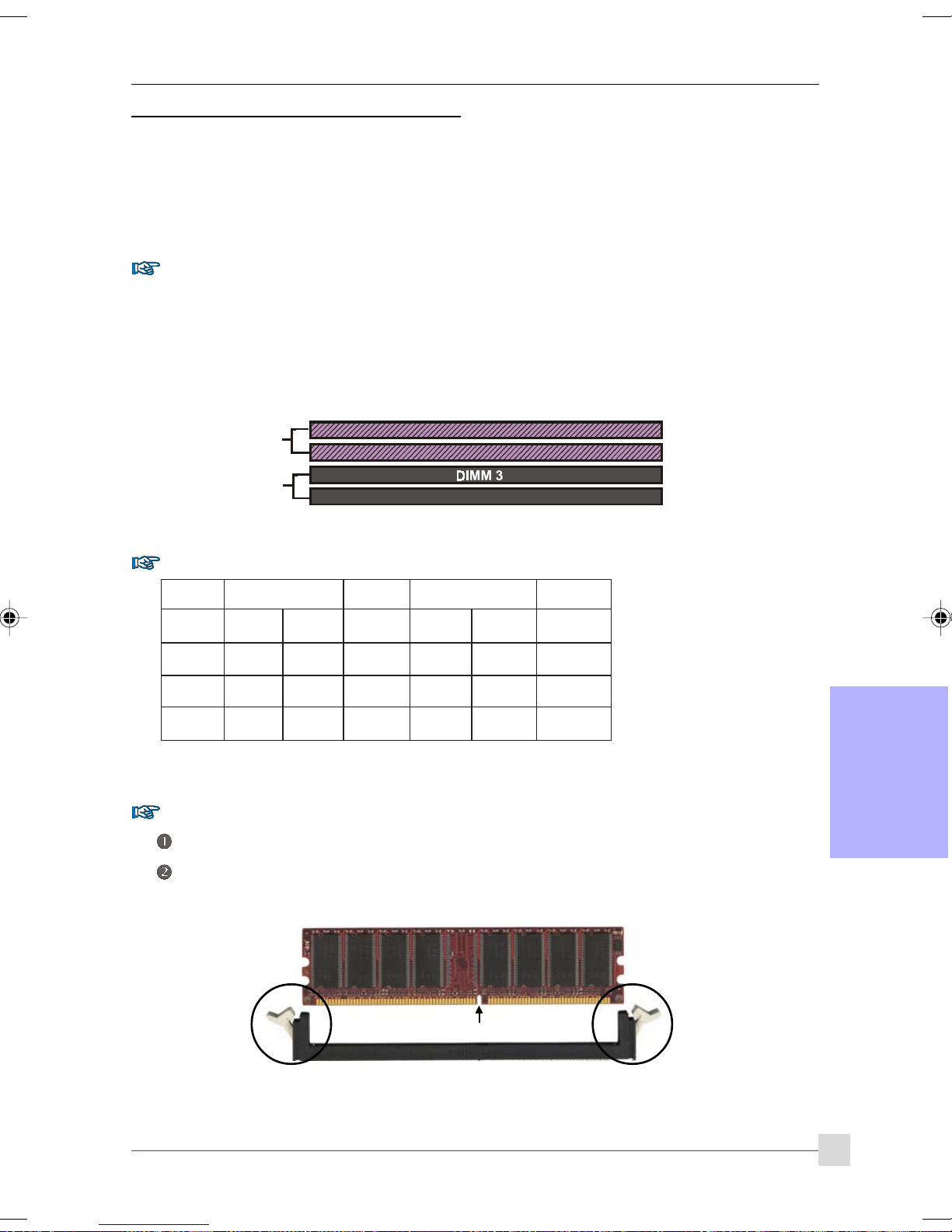
Installation
2-3 Configuration de la mémoire système
La carte-mère peut recevoir quatre modules DIMM 240 broches.
• Prise en charge de 16 Go de modules DDRII SDRAM 533/667/800MHz maximum.
• Prise en charge des configurations DIMM non tamponnées définies dans les spécifications JEDEC DDRII
DIMM.
Interface double canal :
• Accès mémoire double canal pour de meilleures performances système.
• Pour que la fonction double canal puisse fonctionner, les deux canaux doivent avoir la même quantité
de mémoire, les modules devant être de préférence du même type.
• Les quatre sockets DIMM sont répartis en deux couleurs pour voir aider à mieux identifier les paires de
canaux <Figure 1>. Chaque paire de canaux est identifiée par une couleur, p.ex. DIMM1 et DIMM2. Pour
des performances optimales, il suffit de monter les sockets DIMM de la même couleur.
Dual Channel 1
DIMM 1
DIMM 2
<Figure 1>
Dual Channel 2
DIMM 4
Configurations mémoire prises en charge :
MMID1
)tib-46(
1#MMIDSD/SSSD/SSSD/SSSD/SS
2#MMIDSD/SSSD/SS
3#MMIDSD/SSSD
4#MMIDSD/SSSD/SS
MMID2
)tib-46(
/SSSD/SSSD/SS
MMID2
)tib-821(
MMID4
)tib-821(
* SS : DIMM Single-Sided (Une face), DS : DIMM Double-Sided (Double face)
Installation de la mémoire :
Pour installer un module, alignez l’encoche du module DIMM avec le connecteur.
Enfoncez le module à la verticale ainsi qu’illustré dans la figure jusqu’à ce que les clips se referment et que
le module soit fermement enfoncé dans le socle DIMM.
Français
Encoche
9
Page 70
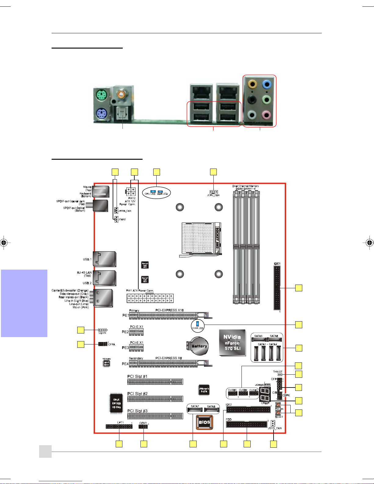
Installation
2-4 P2-4 P
2-4 P
2-4 P2-4 P
Le panneau arrière des E/S de cette carte mère est reproduit ci-dessous. Lorsque vous installez la carte-mère dans
le boîtier de l’ordinateur, utilisez le bouclier E/S fourni pour protéger ce panneau arrière.
2-5 Connecteur2-5 Connecteur
2-5 Connecteur
2-5 Connecteur2-5 Connecteur
oror
t E/S art E/S ar
or
t E/S ar
oror
t E/S art E/S ar
PS/2
Souris
PS/2
Clavier
rièrrièr
ee
rièr
e
rièrrièr
ee
Fiche de sortie S/PDIF
coaxiale
Sortie S/PDIF optique
s inters inter
s inter
s inters inter
nesnes
nes
nesnes
1
4
11
RJ45
LAN
USB2.0 x 4 ports
RJ45
LAN
1
7.1 voies audio
Français
10
3
11
6
5
9
7
13
8
14
15
12
1016
3
2
1
Page 71
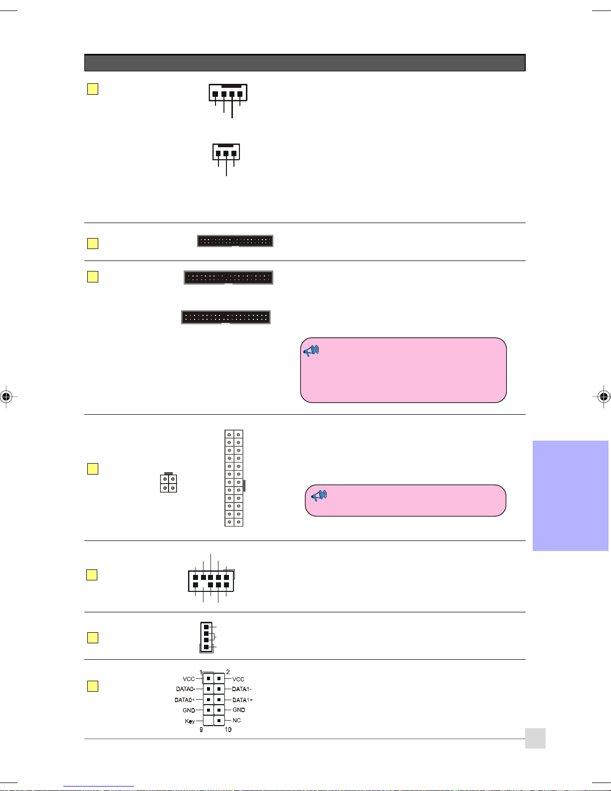
Connecteurs Figure Descriptions
Installation
JCPU_FAN
1
JPWR_FAN
JSYS_FAN
JFAN2
FDD
2
IDE1
3
IDE primaire
IDE2
IDE secondaire
(En option)
Connecteurs du CPU / de l'alimentation / du Châssis /
l'alimentation du ventilateur ES
Control
Sense
Ground
+12V
JCPU_FAN : Connectez le ventilateur du processeur sur ce
connecteur.
JPWR_FAN : Utilisez ce connecteur si vous installez un
ventilateur supplémentaire dans l’unité.
JSYS_FAN : Le ventilateur de châssis apportera une
Ground
Sense
+12V
ventilation suffisante dans le châssis pour
empêcher la surchauffe du processeur.
JFAN2 : Si vous installez le ventilateur à E /S à l'arrière
dans l'unité, connectez à ce connecteur de
ventilateur.
Connecteur pour lecteur de disquette
1
Connecteur IDE primaire
1
Permet de connecter un périphérique IDE, p. ex disque dur et
unité CD-ROM.
Connecteur IDE secondaire
1
Se connecte au disque dur uniquement.
Lorsque deux unités IDE sont utilisées sur le
même connecteur, l’une doit être configurée
en mode Maître et l’autre en mode Esclave.
Pour les détails, veuillez vous reporter au
manuel de l’utilisateur de votre unité.
4
5
6
7
PW1
PW12
CFPA
CD-IN
CUSB3
CUSB4
CUSB5
23
3.3V
+12V
+12V
4
3
+12V+12V
GroundGr ound
2
1
1
11
Front Line-out- R
NC
NC
Key
1
MIC_In
NC
GND
+5V
CD_IN_Right
CD_Reference
CD_IN_Left
2
Front Line-out- L
91
10
NC
24
Ground
+5V
+5V
+5V5VSB
-5VPW-OK
GroundGround
Ground+5V
GroundGround
PS-ON+5V
GroundGround
-12V3.3V
3.3V3. 3V
PW1 : Connecteur d’alimentation ATX 24 broches
PW12 : Connecteur d’alimentation ATX12V 4 broches
Les fiches des câbles ont été conçues de façon à ne pouvoir
entrer que dans un sens.
Les connecteurs d’alimentation PW1 et
PW12 doivent être utilisés simultanément.
Français
CFPA : Connecteur audio du panneau avant
Ce connecteur audio se branche aux fiches audio situées sur le
panneau avant. Reportez-vous au manuel utilisateur pour
connaître le branchement correct.
CD-IN: Connecteurs d’entrée audio CD
Ces connecteurs sont utilisés pour recevoir l’audio venant d’une
unité CD-ROM, d’un tuner TV ou d’une carte MPEG.
CUSB3/CUSB4/CUSB5 : Six barrettes USB2.0
Cette carte-mère comporte six ports USB sur carte
supplémentaires.
Pour pouvoir utiliser ces ports USB supplémentaires, une
barrette USB est requise. Contactez votre revendeur pour
obtenir plus de détails.
11
Page 72
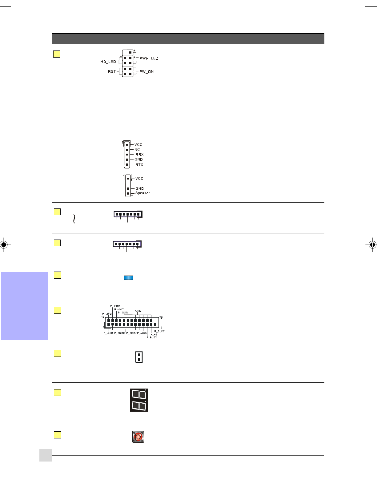
Installation
Connecteurs Figure Descriptions
8
9
CFP
CIR
CSPK
SATA1
SATA6
GND
CFP : Connecteur du panneau avant du boîtier
HD_LED
Ce voyant LED indique l’activité du disque dur.
PWR_LED
Permet de connecter l’indicateur d’alimentation au boîtier du PC.
RST
Permet de connecter l’interrupteur RESET (réinitialisation)
au boîtier du PC.
PW_ON
Permet de connecter le bouton Alimentation au boîtier du PC,
pour allumer le système. Pour éteindre le système, appuyez sur
le bouton alimentation pendant 4 secondes.
CIR : Connecteur IR
Pour la connexion d’un récepteur IrDA.
CSPK : Haut-parleur
Permet de connecter le haut-parleur du boîtier pour les bips du
PC.
1
A+
GND
GND
A-B-
B+
SATA1 ~ SATA6 : Six connecteurs S-ATA II
Ces connecteurs vous permettent de connecter des disques
durs ou des unités optique Série ATA.
10
11
Français
12
13
14
SATA7
SATA8
(En option)
LEDION
LPT1
THM-ST
(En option)
CP80P
GND
1
A+
GND
B+
A-B-
GND
SATA7 ~ SATA8: Deux connecteurs S-ATA II
Ces connecteurs vous permettent de connecter des disques
dur Serial ATA ou des lecteur optiques avec e-SATA.
LEDION:
Les indicateurs DEL intégrés indiquent le statut d'alimentation
du CPU, du chipset et de la DRAM. Vous savez immédiatement
où chercher si le système ne démarre pas.
LPT1: Connecteur de port parallèle (imprimante)
Le port parallèle peut être utilisé pour les imprimantes et autres
périphériques parallèles.
Thermo Stick :
Thermomètre souple qui vous permet de mesurer toute
température par le biais d’un logiciel. Idéal pour surveiller les
températures de la carte VGA, du chipset ou même des
disques durs.
CP80P : LED de débogage port post
Apporte un code POST à deux chiffres montrant pourquoi le
système ne démarre pas. Permet une optimisation rapide et
facile.
Le voyant LED affiche la température du processeur lorsque
vous exécutez le logiciel d’accompagnement Thunder Probe.
EZ-Button
15
12
EZ-Button — RESET, PW-ON :
Ces boutons sur carte vous permettent d’allumer et
d’éteindre facilement le système, ce qui est particulièrement
utile pour déboguer ou tester le système.
Page 73
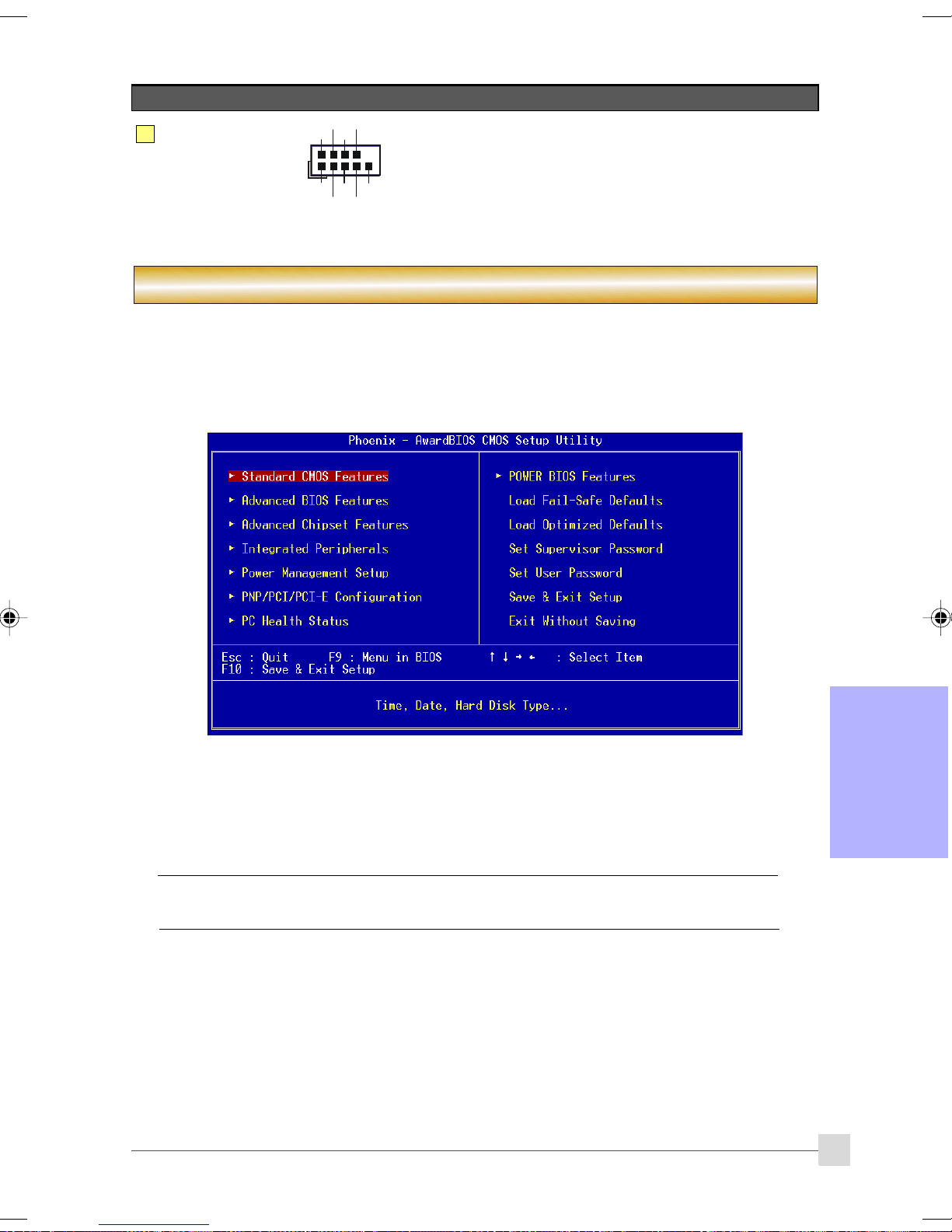
Installation
Connecteurs Figure Descriptions
16
COM1
RI
DSR
CTS
TXD
DTR
10
9
Ground
2
1
DCD
RXD
COM1: Connecteur de port série
Le port série peut être utilisé avec les modems, imprimantes
séries, terminaux d'affichage à distance, et autres
périphériques séries.
RTS
Section 3 -- BIOS Setup
BIOS Setup
Lorsque vous démarrez votre ordinateur pour la première fois, vous devez accéder à l’utilitaire BIOS CMOS Setup.
Allumez l’ordinateur puis appuyez sur la touche <Del> pendant le POST (Test de mise sous tension). L’utilitaire BIOS
CMOS SETUP UTILITY s’ouvre ainsi qu’illustré ci-dessous :
< l’utilitaire CMOS Setup Utility>
Sélectionnez et accédez à la page "Load Optimized Defaults" (Changer les paramètres par défaut optimisés). Cette
page charge les paramètres usine par défaut pour permettre des performances système optimales. Suivez les
instructions simples à l’écran pour mener cette procédure à bien. Appuyez sur "ECHAP" pour quitter et sélectionnez
"Save & Exit Setup" (Enregistrer et quitter le Setup) pour poursuivre l’amorçage.
Pour de plus amples informations concernant les paramètres du BIOS, veuillez vous
reporter au manuel complet sur le CD d’accompagnement.
Français
13
Page 74

Installation
Section 4 -- Pilotes et Utilitaires
Une fois le système d’exploitation installé, vous devez installer les pilotes pour cla arte mère.
Please Select :
Méthode 1
Méthode 2
Insérez le CD d’accompagnement dans le lecteur de CD-ROM et l’écran du menu principal s’affiche. Le menu
principale affiche les liens vers les pilotes, utilitaires et logiciels pris en charge.
Méthode 1
Cette option permet d’installer automatiquement tous les pilotes.
Méthode 2
Cette option permet d’installer les pilotes de façon sélective.
Français
Etape 1 : Cliquez sur “nVIDIA nForce Driver” pour installer le pilote du chipset.
Etape 2 : Cliquez sur “REALTEK High Definition Audio Driver” pour installer le pilote audio.
Auto Installation
Manual Installation
Please install SP1 for Windows XP before installing nForce driver
>> nVIDIA nForce Driver
>> REALTEK High Definition Audio Driver
>> USB 2.0 Driver
>> JMicron PCI Express SATA II and PATA Controller Driver
>> AMD Cool’n’Quiet Processor Driver
Etape 3 : Cliquez sur “USB 2.0 Driver” pour installer le pilote USB 2.0.
Etape 4 : Cliquez sur “JMicron PCI Express SATA II and PATA Controller Driver” Pour installer
le pilote du contrôleur JMicron PCI Express SATA II et PATA.
Etape 5 : Cliquez sur “AMD Cool’n’Quiet Processor Driver” pour installer le pilote des processeurs
de la série AMD.
Les éléments du menu principal sont susceptibles de varier en
fonction du modèle que vous avez acheté.
Lorsque les pilotes ont été installés avec succès, vous pouvez installer la suite logicielle d'utilitaires.
14
Page 75

Installation
Section 5 -- Ghost BIOS
Ghost BIOS vous permet de redémarrer suite à une corruption du BIOS, alors qu'habituellement il serait impossible de
redémarrer. Ghost BIOS vous permet de réparer le BIOS vous-même sans avoir à retourner la carte mère en
réparation.
Préparation pour pouvoir utiliser Ghost BIOS :Préparation pour pouvoir utiliser Ghost BIOS :
Préparation pour pouvoir utiliser Ghost BIOS :
Préparation pour pouvoir utiliser Ghost BIOS :Préparation pour pouvoir utiliser Ghost BIOS :
1. Installez l'utilitaire Thunder Flash qui se trouve sur le CD de la suite logicielle.
2. Créez une disquette de récupération du BIOS (BRD) avec cet utilitaire.
“LOAD”
Création d'une disquette de récupération du BIOS :
1. Lancez l'utilitaire Thunder Flash.
2. Connectez-vous à Internet.
3. Insérez une disquette vierge dans le lecteur de disquettes puis cliquez sur "LOAD".
4. Conservez cette disquette en lieu sûr pour une utilisation future.
Si le BIOS se rSi le BIOS se r
Si le BIOS se r
Si le BIOS se rSi le BIOS se r
Lorsque le BIOS est corrompu ou défaillant, redémarrez le système et l'écran suivant apparaîtra. Vous avez le choix
de récupérer le BIOS à partir de la disquette BRD créée précédemment ou à partir du CD contenant les pilotes.
etretr
etr
etretr
ouvouv
ouv
ouvouv
e core cor
e cor
e core cor
rr
ompu :ompu :
r
ompu :
rr
ompu :ompu :
Français
1. Si vous choisissez la récupération à partir de la disquette de récupération du BIOS (BRD), insérez la
disquette créée précédemment puis cliquez sur "1".
2. Si vous choisissez la récupération à partir du CD contenant les pilotes de la carte mère, insérez ce CD
dans le lecteur puis cliquez sur "2".
Remarquez que le CD des pilotes système permet uniquement une restauration du BIOS en
mode sécuritaire. Le BIOS adéquat doit être mis à jour après la restauration.
15
Page 76

Installation
Si cet écran s’affiche, cela signifie que la version du BIOS n’est pas à jour. Veuillez vous
reporter à la procédure Magic Flash pour mettre à jour le BIOS.
Français
16
Page 77

Introduction
1-1
目次目次
目次
目次目次
パッケージの内容パッケージの内容
パッケージの内容
パッケージの内容パッケージの内容
A. メインボード
B. ユーザーズマニュアル
C. フロッピードライブケーブル
D. HDDドライブケーブル
E. CD (ドライバとユーティリティ)
F. I/Oシールド
G. SATA II データケーブル
セクションセクション
セクション1 --
セクションセクション
オプションのアイテムオプションのアイテム
オプションのアイテム
オプションのアイテムオプションのアイテム
USER’S
MANUAL
はじめにはじめに
はじめに
はじめにはじめに
H. Extra USB2.0ポートケーブル
I. COMポートブラケット
J. プリンタポートブラケット
K. サーモスティックケーブル
L. リアI/Oファン
オプションのアイテムを選択する場合、販売
店に連絡してその方法をお尋ねください。
E
C
D
A
G
RAIDRAID
RAIDドライブにWindows XP/2000をインストールしているとき、O /SセットアップではRAIDドライバを含むフ
ロッピーディスクが要求されます。このセットアップは、このドライバフロッピーの作成方法を示します。
1. PCにバンドルされたCDをCD-ROMドライブに挿入します
2. メインメニュー画面が表示されます (自動実行機能)
3. 「Raid Floppy」ページを選択します
をセットアップする場合をセットアップする場合
RAID
をセットアップする場合
RAIDRAID
をセットアップする場合をセットアップする場合
H
B
I J
K
F
L
日本語日本語
日本語日本語
日本語
4. 空のフロッピーをA : ドライブに挿入します
5.必須RAIDコントローラドライバをクリックして、フロッピーへのコピーを開始します
1
Page 78

Introduction
1-2
日本語
日本語日本語
日本語日本語
2
メインボードの機能メインボードの機能
メインボードの機能
メインボードの機能メインボードの機能
簡単な概要簡単な概要
簡単な概要
簡単な概要簡単な概要
Socket AM2
Socket AM2(940ピン)ベースのマザーボードはAMD AthlonTM AM2プロセッサベースシステムのパフォーマン
スを向上させており、次世代のプラットフォームとして期待されています。
TM
Athlon
をチェックしてください。
チップセットチップセット
チップセット
チップセットチップセット
ボードはnVidia nForce 570 SLIチップセットで設計され、ほとんどの革新的テクノロジと機能を搭載したパ
フォーマンスと安定性を特徴としています。
nVidiaチップセットの詳細については、nVidiaのWebサイト:http://www.nVidia.comにアクセスしてください。
AM2プロセッサが提供するすべての新機能については、AMDのWebサイト:http://www.amd.com
DDRII
DDRIIはDDRメモリ・テクノロジーの新しい時代の到来を告げます。DDRIIメモリは高速、広いデータ帯域
幅、低電力消費を実現します。
PCI-Express (PCI-E)
現在のPCIバスを継承する次世代の周辺インターフェイス。小さなスロットサイズと250MB/秒 (PCI-E*1)ま
たは4GB/秒(PCI-E*16)の最大転送、PCI-ExpressがPCIボトルネックを克服しています。
NVIDIA SLI
NVIDIA SLiTMテクノロジは複数のPCI Express GPUを1つの拡張可能なシステムに結合することによっ
て、PCパフォーマンスを革命的に向上させています。ゲーマーやオーバークロッカーは、デュアルGPU
が3Dグラフィックスとパフォーマンスの大幅なアップにつながることを知っています。
デュアルチャンネルデュアルチャンネル
デュアルチャンネル
デュアルチャンネルデュアルチャンネル
DDRIIメモリのデュアルチャンネルをサポートしてメモリバンド幅を2倍に拡張し、システムパフォーマン
スを大幅に向上させています。
ハードウェアモニタリングハードウェアモニタリング
ハードウェアモニタリング
ハードウェアモニタリングハードウェアモニタリング
ハードウェアモニタリングでは、システム操作とステータスのさまざまな側面をモニタします。これに
は、CPU温度、電圧、ファン速度(RPM)が含まれます。
デュアルデュアル
デュアルGbE LAN
デュアルデュアル
2つのオンボードGigabit-LANコントローラGigabit-LANのこのツインセットは従来のバンド幅の障壁を打
ち破り、内部ネットワークと外部ネットワークの間で最大1000Mbpsのバンド幅を利用できるようになっ
ています。
S-ATA II
S-ATA IIは第二世代のSATAインターフェイスで、転送速度を300MB/秒まで2倍の高めています。NCQをサ
ポートして、ストレージデバイス用に高速な読み取り速度を実現しています。
SATA RAID
NVドライバのサポートにより、チップセットのSATA IIポート、RAID 0、1、0+1、5、JBODで使用できる
RAID機能。
その他のその他の
その他のS-ATA II
その他のその他の
S-ATA IIコントローラを特別に追加して、RAID機能を搭載したJMicronのJMB363の形式でさらに多くの
S-ATA IIポートを拡張することができます。
((
e-SATA
この新しい標準により、外部SATAドライブをUSBデバイスに似たシステムにホットプラグできます。
USB2.0、RAID機能、ポートマルチプライヤ機能より6倍の転送速度を実現するe-SATAは、難しい設定な
ど一切なしで目に見えないほどの早いパフォーマンスを達成します。この機能は、JMicronのJMB363コ
ントローラからS-ATAポートでのみ使用できます。
オプションオプション
(
オプション
((
オプションオプション
((
オプションオプション
(
オプション
((
オプションオプション
))
)
))
))
)
))
USB2.0
一般のUSB標準では、最大480Mbpsの転送速度を持つ周辺機器を差し込みながら、一方で旧式のUSB1.1デ
バイスと下位互換性も維持しています。
8ch
8チャンネルオーディオを実現してDVDムービーやゲームから最新のオーディオリアリズムがもたらされま
す。ホームシアターシステムに最適。
Page 79

Introduction
AMD Cool'n'QuietTM Technology
システムが活動停止モードに入ると、AMDのCool'n'QuietTM TechnologyはCPUの動作電圧を下げます。これ
により、熱放散が削減されてファン速度を効率的に落とし、PCのノイズを抑えます。
NVIDIA
nForce製品のかつて例を見ないほど多くの設計を新しく取り込んで、PCセキュリティソリューションの高
いパフォーマンスと強化された信頼性を実現。機能は多くのスタンドアロンファイアウォールに比べ格段
に向上しています。
NVIDIA ActiveArmorTM
ハードウェアのCPUを大量に消費するパケットフィルタリングタスクをオフロードすることによって、最
高のシステムパフォーマンスを実現する一方でネットワークセキュリティを強化し、ユーザーに高速で
安全性の高いP C ネットワーキング環境を提供しています。
ファイアウォール(オプション)ファイアウォール(オプション)
ファイアウォール(オプション)
ファイアウォール(オプション)ファイアウォール(オプション)
(オプション)(オプション)
(オプション)
(オプション)(オプション)
特殊機能特殊機能
特殊機能
特殊機能特殊機能
BIOS
H/W
機能機能
機能:
機能機能
Ghost BIOS
BIOSが損傷してシステムを起動できなくなっても心配はいりません。オンボードのバックアップBIOSがい
くつかの簡単なステップでメインBIOSを救出し回復します。
Thunder Probe
ハードウェア診断ソフトウェアで、さまざまなハードウェアの電圧、温度、速度をモニタします。スマー
トファンと呼ばれる、独創的なファンコントロール機能も内蔵されています。
Thunder Flash
Windowsベースの革新的なツールで、安全で簡単なBIOSレスキュー機能、BIOSフラッシュ機能、パーソナ
ル起動画面が用意されています。
Magic Health
起動ごとにシステムハードウェアステータスを報告し、障害をいち早く検出します。ハードウェアステー
タスのモニタには、CPU温度、CPU/メモリ/チップセット電圧、シャーシファンのファンRPM速度、CPU
ファンと電源装置ファンが含まれます。
EZ-Boot
「ESC」を押すと、起動可能がデバイスが選択されます。BIOSメニューを検索し、変更して再起動する煩
わしさから開放されます。
PowerBIOS
BIOSを通して、幅広いオーバークロック設定をサポートします。さまざまな調整可能機能にはFSB/メモリ/
チップセット電圧微調整が含まれます。
機能機能
機能:
機能機能
Post Port
オンボードのLEDディスプレイトラブルシューティングデバイスで、起動問題を容易に検出できるようにします。
QuickSPDIF
オンボードのSPDIFアウトコネクタで、マルチチャンネルスピーカーに素早く接続します。ケーブル回りを
すっきりさせるだけでなく、ロスのないロスフリーディジタルオーディオが提供されて、明晰なサウンド
でDVDムービーやゲームをお楽しみいただけます。
EZ-Button
オンボードに配置された役に立つ電源オンボタンで、特にシステムをデバッグまたはテストしている間
に、システムの電源のオン/オフを簡単に切り替えます。
LEDION
CPU、チップセット、DRAMの電源ステータスを表示するオンボードLEDインジケータ。システムが起動
できなかった場合、どこを調べればいいかすぐに分かります。
Thermo Stick (
柔軟性に富むサーモメーターで、ソフトウェアにより温度を測定します。VGAカード、チップセット、また
はディスクドライバの温度のモニタに適しています。
オプションオプション
オプション)
オプションオプション
3
日本語日本語
日本語日本語
日本語
Page 80

Introduction
1-3
メインボード仕様メインボード仕様
メインボード仕様
メインボード仕様メインボード仕様
プロセッサプロセッサ
プロセッサ
プロセッサプロセッサ
Socket-AM2( 940ピン) ベースの2.0GTs 16x16ハイパートランスポートプロセッサを搭載した、AMD
Athlon-AM2をサポート
VMM(仮想マシンモニタリング)をサポート
チップセットチップセット
チップセット
チップセットチップセット
nVidia nForce 570 SLIチップセット
メインメモリメインメモリ
メインメモリ
メインメモリメインメモリ
4つの240ピンバッファなし非ECC DDRII SDRAM DIMMソケット
256Mb/512Mb/1Gbテクノロジにデュアルチャンネルアーキテクチャを組み込んだ、片面または両面
1.8v DDRII-533/667/800 DIMMをサポート。
最大16GBのメモリサイズをサポート
拡張スロット拡張スロット
拡張スロット
拡張スロット拡張スロット
3つのPCIコネクタがPCI v2.3に準拠
2つのPCI-E (x1)コネクタがPCI Express 1.0aに準拠
2つのPCI-E (x16)コネクタがPCI Express 1.0aに準拠でSLiテクノロジをサポート
USB
10つのUSBコネクタが埋め込まれたUSBコントローラ(背面パネルに4つのコネクタ)によるUSB2.0に準拠
LAN
オンボードMarvell 88E1116 GigabitイーサネットPHYから2つのGigabitイーサネット
日本語
日本語日本語
日本語日本語
P-ATA IDE
埋め込まれたIDEコントローラによる、UDMA-33/66/100/133をサポートする1つのIDEインターフェイス
(最大2つのIDEデバイス)
S-ATA RAID
RAID 0、1、0+1、5で最高300MB/秒を実現する4つのS-ATA IIポート
その他のその他の
その他のS-ATA II
その他のその他の
JMicronのJMB363 PCI-Expressから2S1P コントローラとe-SATAサポートまで、2つのS-ATA IIポート
と1つのP-ATAポート。
I/O
オンボードのEPoX EP1308 LPCバスI/Oコントローラ
PS/2キーボードとマウス、FDD、パラレル、シリアル、IrDA用古いタイプの周辺機器インターフェイス
(v1.0準拠)。
ハードウェアモニタリングをサポートして、ファン速度モニタリングとCPU温度検知を実行
インテリジェントなCPUファン(PWM)のファン速度コントロールで、静かな操作を実現
BIOS
AwardプラグアンドプレイBIOSを搭載したFlash EEPROM
EZ Bootをサポートして高速起動可能デバイスを選択
Magic Healthをサポートしてシステム起動時にシステムハードウェアステータスを報告
Ghost BIOSをサポートしてBIOSの回復
オーディオオーディオ
オーディオ
オーディオオーディオ
オンボードRealtek ALC8xxハイディフィニションオーディオ準拠CODECによる8チャンネル
オーディオ
- CD-Inのサポート
- Jack detectionをサポートして簡単なオーディオデバイスのインストール
((
オプションオプション
(
オプション
((
オプションオプション
))
)
))
4
Page 81

- 背面パネルオーディオジャック設定
8チャンネルALC8xx設定の場合
モジュラージャックの色
ライトブルー
周辺機器のインターフェイス周辺機器のインターフェイス
周辺機器のインターフェイス
周辺機器のインターフェイス周辺機器のインターフェイス
))
背面パネルで背面パネルで
)
背面パネルで
背面パネルで背面パネルで
))
PS/2キーボードとマウスポート
1つのS/PDIFアウト同軸ジャック
1つのS/PDIFアウト光学
1つのRJ45 LANコネクタ
4つのUSB2.0ポート
6つのオーディオジャック
))
オンボードコネクタとピンヘッダオンボードコネクタとピンヘッダ
)
オンボードコネクタとピンヘッダ
オンボードコネクタとピンヘッダオンボードコネクタとピンヘッダ
))
1つのフロッピードライブコネクタ
1つのATA-100/133 IDEコネクタ
1つのATA-100/133 IDEコネクタ(オプション)
6つの予備のUSB2.0ポート
1つのCD-INコネクタ
1つのIRコネクタ
1つのパラレル(プリンタ)コネクタ
1つのシリアルポート(COM1)コネクタ
6つのS-ATA IIコネクタ
2つのS-ATA IIコネクタ(オプション)
4つのファンコネクタ
eulBthgiLni-eniLni-eniLni-eniL
ライム
emiLtuo-eniLtuo-oeretstnorFtuo-oeretstnorF
ピンク
kniPni-ciMni-ciMni-ciM
グレー
yarGtuo-oeretsediS
黒
kcalBtuo-oeretsraeRtuo-oeretsraeR
オレンジ
egnarOrefoowbuS&retneCrefoowbuS&retneC
2 チャンネル
roloCkcaJenohP lennahc2 lennahc6 lennahc8
ラインイン
ラインアウト
マイクイン
フロントステレオアウト
センター& サブウーファ
noitarugifnoC058CLAhc8roF
6 チャンネル
ラインイン
マイクイン
リアステレオアウト
Introduction
8 チャンネル
ラインイン
フロントステレオアウト
マイクイン
サイドステレオアウト
リアステレオアウト
センター& サブウーファ
フロントパネルコントローラフロントパネルコントローラ
フロントパネルコントローラ
フロントパネルコントローラフロントパネルコントローラ
リセットとソフトオフスイッチのサポート
HDD & 電源LEDのサポート
PCスピーカーをサポート
フロントパネルオーディオコネクタのサポート
特殊機能特殊機能
特殊機能
特殊機能特殊機能
KBPO機能をサポート -– キーボードの電源オン、キーボードからコンピュータの電源オン
PMEによる呼び起こしLANのサポート
オンボードポストポートLEDディスプレイでシステムのデバッグ
PowerBIOSで、優れたオーバークロック機能:
- プログラマブルFSBクロック出力周波数(1MHz微調整)
- BIOS調整可能CPUマルチプライヤ、FSBクロック、DIMM周波数のサポート
- BIOS調整可能CPUコア電圧、チップセット電圧、DIMM電圧のサポート
EZ-Buttonのサポート -– オンボードの使いやすい電源オンボタンでシステムの電源のオン/オフを簡単
に切り替え
LEDION
Thermo Stick温度をサポート(オプション)
Ghost BIOSのサポート -- 簡単なステップで、BIOSを救出、回復し、BIOSが損傷する心配をしなくても
済みます。
のサポートのサポート
のサポート
のサポートのサポート
-– CPU、 DDR、チップセット用のオンボードLED電源インジケータ
5
日本語日本語
日本語日本語
日本語
Page 82
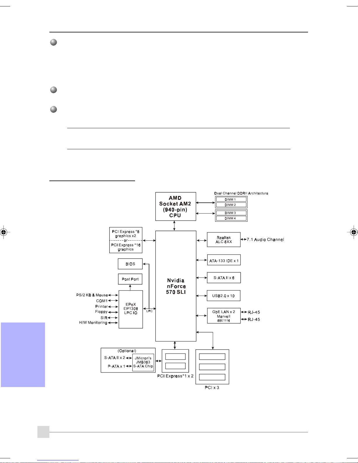
Introduction
Windows
Thunder Probeのサポート -- ハードウェア診断ソフトウェアがさまざまなハードウェアの電圧、温
度、速度をモニタします。このサポートには、スマートファンと呼ばれる独創的なファンコントロール
機能も組み込まれています。
Thunder Flashのサポート -- Windowsベースの革新的なツールで、安全で簡単なBIOS救出機能、BIOS
フラッシュ機能、パーソナル起動画面が用意されています。
フォームファクタフォームファクタ
フォームファクタ
フォームファクタフォームファクタ
305mm x 245 mm ATXサイズ
対応対応
OSOS
対応
OS
対応対応
OSOS
Windows 2000, Windows XP
ご購入いただいたモデルによっては、コンポートネントがオプションになっておりご
1-4
システムブロック図システムブロック図
システムブロック図
システムブロック図システムブロック図
用の強力なユーティリティ用の強力なユーティリティ
用の強力なユーティリティ
用の強力なユーティリティ用の強力なユーティリティ
利用いただけない場合もあります。
日本語
日本語日本語
日本語日本語
6
Page 83
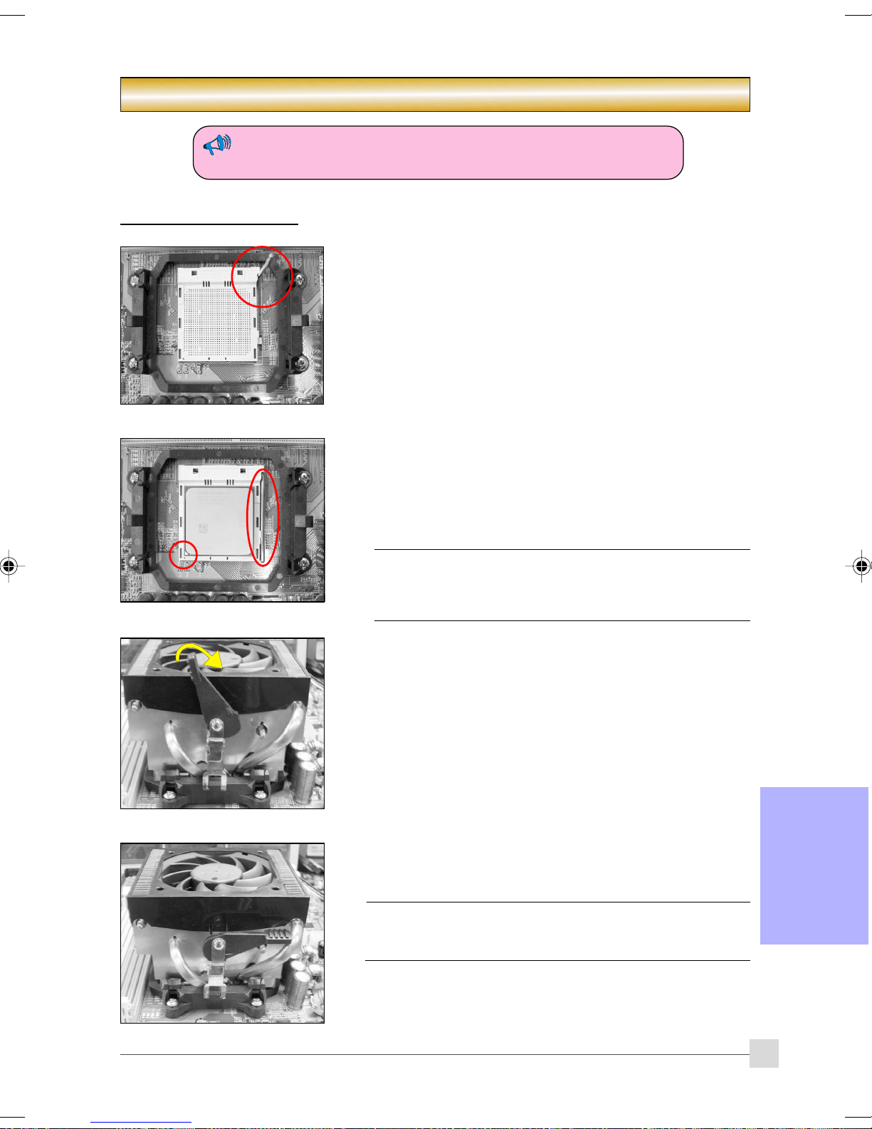
Installation
2-1
CPUCPU
インストールインストール
CPU
インストール
CPUCPU
インストールインストール
(1)
セクションセクション
セクション2 --
セクションセクション
コンピュータ・シャーシ内のデバイスを着脱する場合は、必ず電源を
切ってから行ってください。
ステップステップ
ステップ
ステップステップ
作動レバーを持ち上げてソケットを開きます。
ステップステップ
ステップ
ステップステップ
(1) 図に示すように、CP Uのピン1をCP Uソケットのピン1に合わせま
す。CPUを挿入し、ソケットに完全にセットされていることを確
認します。
(2)
(2) 作動レバーを下げ、ロックすることによってソケットを閉じま
す。
インストールインストール
インストール
インストールインストール
11
1
11
22
2
22
C P U は間違った方向への挿入を防ぐためにキーが付いていま
す。C P U をソケットに無理に押し込まないでください。楽に
入らない場合、方向が間違っていないかチェックしてくださ
い。
ステップステップ
ステップ
ステップステップ
図に示すようにヒートシンクを挿入します。 矢印の方向にクリッ
プを押して、アセンブリをCPUソケットに固定します。
ステップステップ
ステップ
ステップステップ
CPUファンの電源をメインボードのCPUファンコネクタに差し込みま
す。取り付けが完了しました。
• C P Uの過熱による損傷を避けるには、A M Dが推奨する熱コ
33
3
33
44
4
44
ンポウンドと正規のヒートシンクが必要となります。
• ヒートシンクの熱コンポウンド/ 接着剤をC P U に塗布します。
日本語日本語
日本語日本語
日本語
7
Page 84
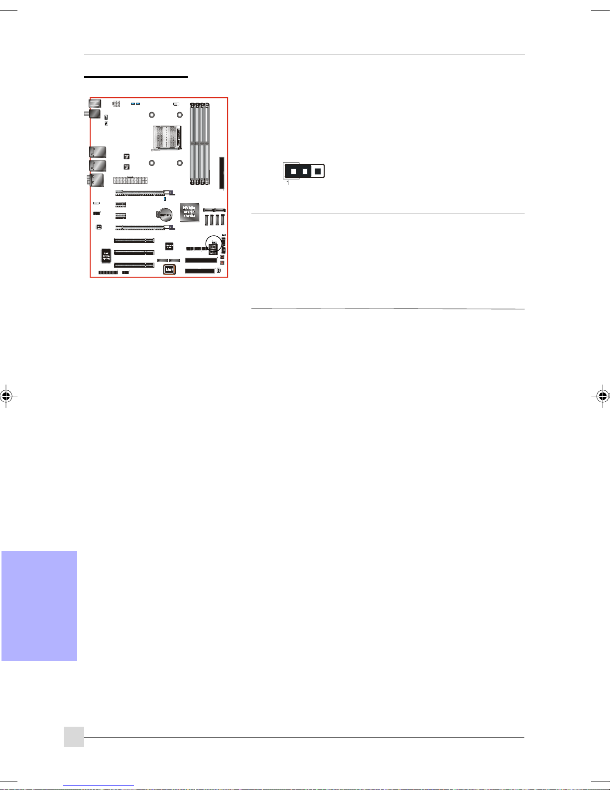
Installation
2-2
ジャンパ設定ジャンパ設定
ジャンパ設定
ジャンパ設定ジャンパ設定
JCMOS: クリアCMOSデータジャンパ
CMOSデータが破損した場合、または管理者またはユーザーパスワー
ドを忘れた場合、CMOSデータを消去してシステムを再設定し、ROM
BIOSに保存されたデフォルト値に戻してください。
設定:
1-2: 標準(デフォルト)
2-3: クリアCMOS
CMOSデータをクリアするには、以下のステップに従ってくださ
い。
1. システムの電源をオフにします。
2. ジャンパの位置を「1-2」から「2-3」に数秒間変えます。
3. ジャンパの位置を「1-2」に戻します。
4. システムの電源をオンにし、<Del>キーを押し下げてBIOS
セットアップに入ります。
日本語
日本語日本語
日本語日本語
8
Page 85
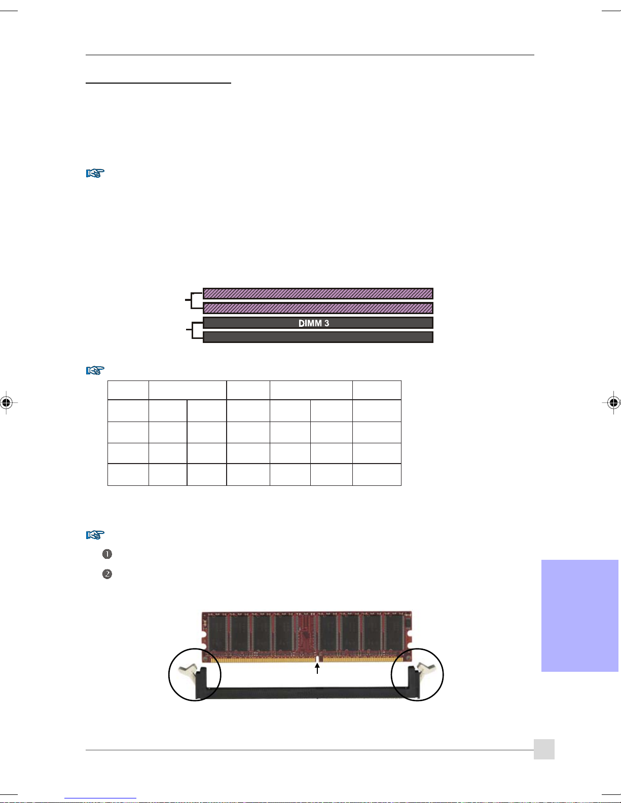
Installation
アルチャンネル
アルチャンネル
2-3
システムメモリ設定システムメモリ設定
システムメモリ設定
システムメモリ設定システムメモリ設定
メインボードは4つの 240ピンDIMMに対応しています。
• 最大16GBの533/667/800MHz DDRII SDRAMをサポートします。
• JEDEC DDRII DIMM仕様で定義されたバッファなしDIMM設定をサポートします。
デュアルチャンネルインターフェイスデュアルチャンネルインターフェイス
デュアルチャンネルインターフェイス:
デュアルチャンネルインターフェイスデュアルチャンネルインターフェイス
• デュアルチャンネルメモリアクセスでは、システムパフォーマンスが向上します。
• デュアルチャンネルで操作するには、両方のチャンネルを同じ容量の、できれば同じタイプのメモリ
を取り付ける必要があります。
•4つのDIMMソケットはチャンネルペアを識別しやすいように2色に分けられています<図1>。それぞれ
のデュアルチャンネルペアには、同じ色、例えばDIMM1とDIMM2があります。
スを達成するには、同じ色のスを達成するには、同じ色の
スを達成するには、同じ色のDIMM
スを達成するには、同じ色のスを達成するには、同じ色の
Dual Channel 1
ソケットをマウントします。ソケットをマウントします。
ソケットをマウントします。
ソケットをマウントします。ソケットをマウントします。
DIMM 1
DIMM 2
DIMM 2 DIMM 4 デュ
1 DIMM 1 デュ
2
最高のパフォーマン最高のパフォーマン
最高のパフォーマン
最高のパフォーマン最高のパフォーマン
<図1>
Dual Channel 2
DIMM 4
サポートされるメモリ設定サポートされるメモリ設定
サポートされるメモリ設定:
サポートされるメモリ設定サポートされるメモリ設定
MMID1
)tib-46(
1#MMIDSD/SSSD/SSSD/SSSD/SS
2#MMIDSD/SSSD/SS
3#MMIDSD/SSSD
4#MMIDSD/SSSD/SS
* SS: 片面DIMM、DS: 両面DIMM
メモリの取り付けメモリの取り付け
メモリの取り付け :
メモリの取り付けメモリの取り付け
MMID2
)tib-46(
/SSSD/SSSD/SS
MMID2
)tib-821(
MMID4
)tib-821(
取り付けるには、DIMMモジュールの切り込みをコネクタに合わせます。
図に示すように、白いクリップが閉じてモジュールがDIMMソケットにぴったり適合するまで下にまっす
ぐ押します。
日本語日本語
日本語日本語
日本語
切り込み
9
Page 86
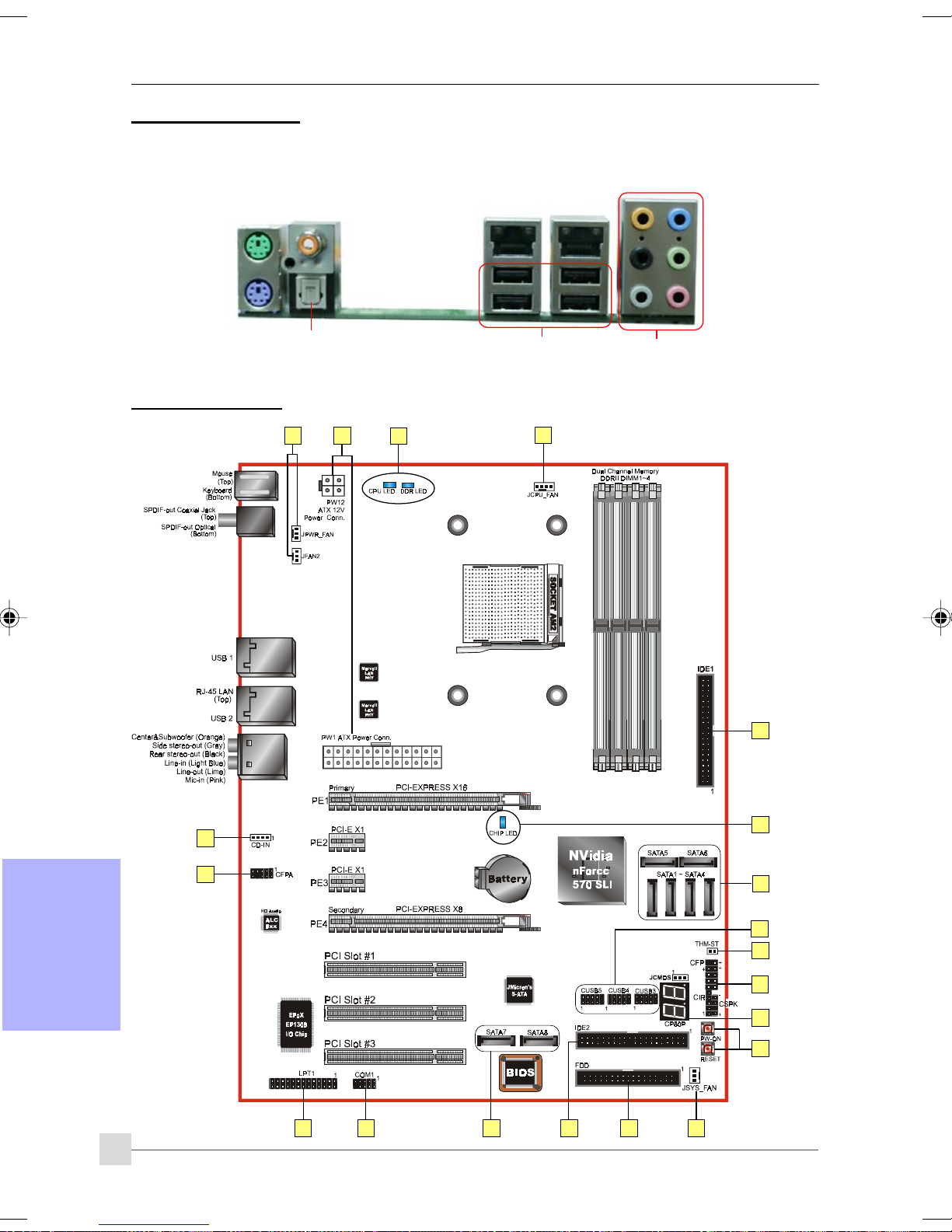
Installation
背面背面
2-4
背面IO
背面背面
このマザーボードのI/O背面パネルを以下に示します。メインボードをコンピュータケースに取り付けるとき、バ
ンドルされたI/Oシールドを使用してこの背面パネルを保護します。
マウス
キーボード
PS/2
PS/2
ポートポート
ポート
ポートポート
S/PDIFアウト
同軸ジャック
S/PDIFアウト光学
RJ45
LAN
USB2.0 x 4 ports
RJ45
LAN
7.1 オーディオチャンネル
2-5 内部コネクタ
1 4
11
1
日本語
日本語日本語
日本語日本語
10
3
6
11
5
9
7
13
8
14
15
12
1016
3
2
1
Page 87
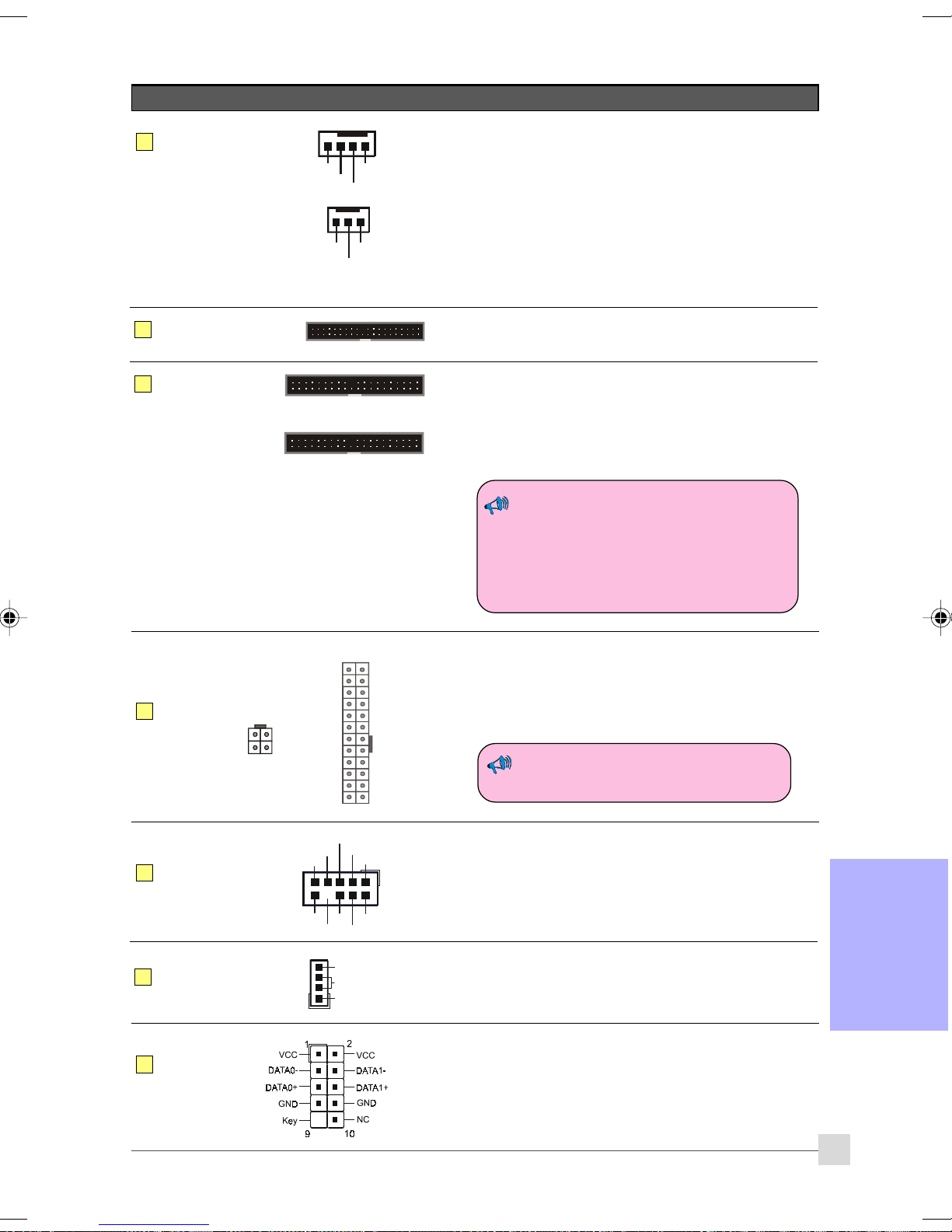
コネクタコネクタ
コネクタ
コネクタコネクタ
図図
図
図図
説明説明
説明
説明説明
Installation
JCPU_FAN
1
JPWR_FAN
JSYS_FAN
JFAN2
FDD
2
IDE1
3
プライマリIDE
IDE2
セカンダリIDE
(オプション)
1
1
Control
Sense
Ground
1
+12V
+12V
Ground
Sense
CPU / 電源 / シャーシ / IOファン電源コネクタ
JCPU_FAN: CPUファンをこのコネクタに接続します。
JPWR_FAN: 装置に追加ファンを取り付ける場合、このコ
ネクタを使用します。
JSYS_FAN: シャーシファンはシャーシに適切な空気を流
して、CPUの過熱を防いでいます。
JFAN2: 装置にリアI/Oファンを取り付けている場合、
このファンコネクタに接続します。
フロッピードライブコネクタ
プライマリIDEコネクタ
IDEデバイス、つまりHDDやCD-ROMデバイスに接続します。
セカンダリIDEコネクタ
HDDデバイスのミニ接続します。
同じコネクタで2つのIDEドライブを使用し
ているとき、1つをマスタモードに、もう1
つをスレーブモードに設定する必要があり
ます。詳細については、ディスクドライブ
のユーザーズマニュアルを参照してくださ
い。
4
5
6
7
PW1
PW12
CFPA
CD-IN
CUSB3
CUSB4
CUSB5
23
24
3.3V
+12V
+12V
4
3
+12V+12V
GroundGround
2
1
11
1
Front Line-ou t-R
NC
NC
NC
Key
+5V
CD_IN_Right
CD_Reference
CD_IN_Left
MIC_In
GND
Front Line-ou t-L
91
10
NC
1
Ground
+5V
+5V
+5V5VSB
-5VPW-OK
GroundGround
Ground+5 V
Groun dGround
PS-ON+5 V
Groun dGround
-12V3.3V
3.3V3.3V
2
PW1: 24ピンATX電源コネクタ
PW12: 4ピンATX12V電源コネクタ
電源ケーブルのプラグは一方向にしかフィットしないように
設計されています。
PW1とPW12電源コネクタは同時に使用す
る必要があります。
CFPA: 前面パネルオーディオコネクタ
このオーディオコネクタはフロントパネルのオーディオ
ジャックに接続します。
ケースのマニュアルを参照して、ピンアウト名を確認してく
ださい。
CD-IN: CDオーディオインコネクタ
これらのコネクタはCD-ROMドライブ、TVチューナー、MPEG
カードからオーディオを受信するために使用されます。
CUSB3/CUSB4/CUSB5: 6つのUSB2.0ヘッダ
このメインボードには、6つの追加オンボードUSBポートが組
み込まれています。
これらの追加AUSBポートを使用するには、USBブラケットが
必要です。詳細については、販売店にお問い合わせくださ
い。
11
日本語日本語
日本語日本語
日本語
Page 88
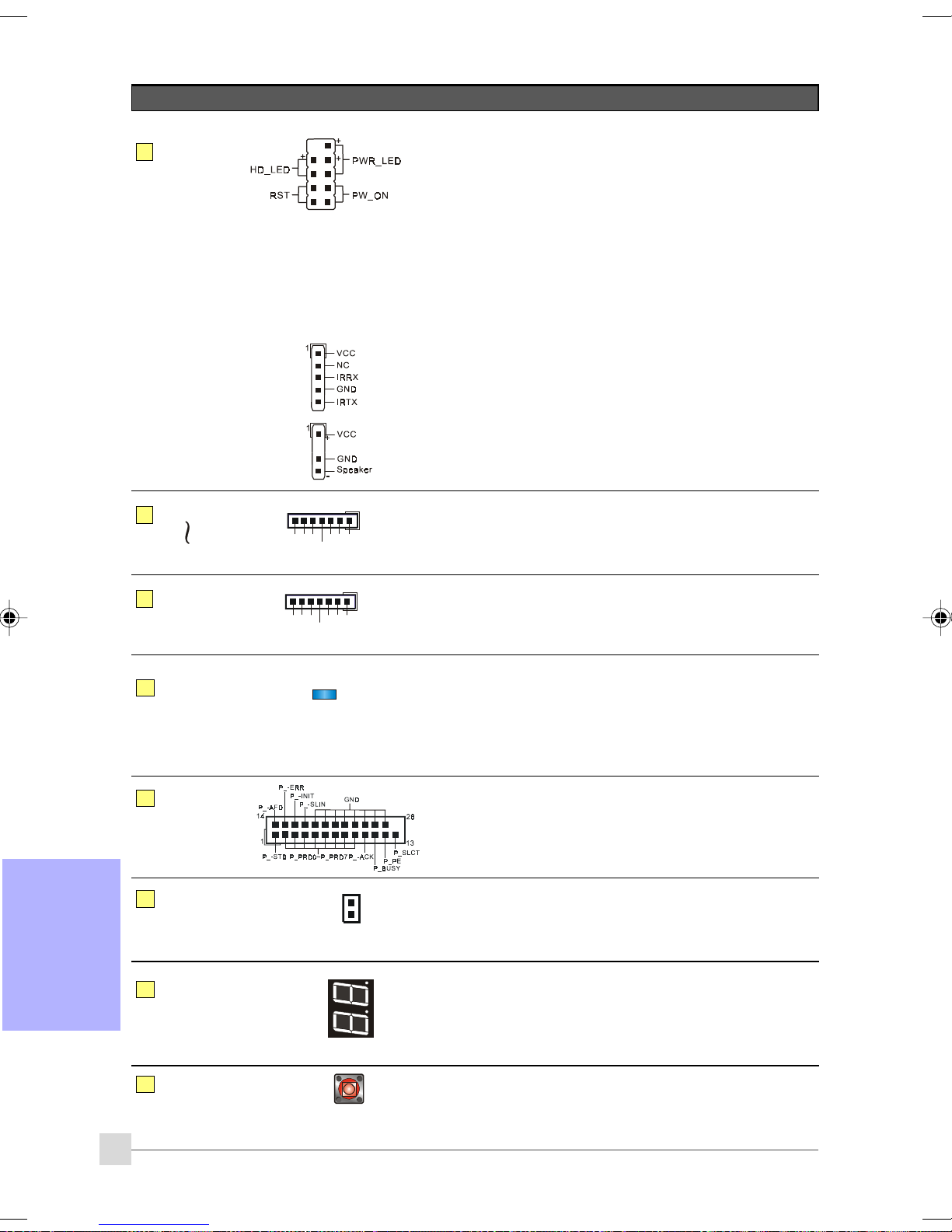
Installation
コネクタコネクタ
コネクタ
コネクタコネクタ
CFP
8
図図
図
図図
説明説明
説明
説明説明
CFP: ケース 前面パネルコネクタ
HD_LED
This LEDはハードドライブの動作を示します。
PWR_LED
電源インジケータをPCケースに接続します。
RST
RESETスイッチをPCケースに接続します。
PW_ON
電源ボタンをPCケースの電源ボタンに接続し、システム
の電源をオンにします。システムの電源をオフにするに
は、電源ボタンを4秒間押します。
CIR
CSPK
SATA1
9
SATA6
SATA7
10
SATA8
(オプション)
11
LEDION
LPT1
12
GND
GND
CIR: IRコネクタ
IrDAレシーバー装置への接続用です。
CSPK: スピーカー
PCのビープ音を出すためにケースのスピーカーに接続しま
す。
1
A+
GND
GND
GND
A-B-
1
A+
GND
A-B-
B+
B+
SATA1 ~ SATA6: 6つのS-ATA IIコネクタ
これらのコネクタにより、シリアルATA HDDまたは光ドライ
ブタイプに接続できます。
SATA7 ~ SATA8: 2つのS-ATA IIコネクタ
これらのコネクタにより、シリアルATA HDDまたは光ド
ライブタイプをe-SATAに接続できます。
LEDION:
CPU、チップセット、DRAMの電源ステータスを表示
するオンボードLEDインジケータ。システムが起動で
きなかった場合、どこを調べればいいかすぐに分かり
ます。
LPT1:パラレルポート(プリンタ)コネクタ
パラレルポートはプリンタとその他のパラレルデバイスに対
して使用できます。
日本語日本語
(オプション)
CP80P
14
EZ-Button
15
THM-ST
13
日本語
日本語日本語
12
Thermo Stick:
柔軟性の高いサーモメーターでは、ソフトウェアにより温
度を測定できます。VGAカード、チップセットまたはディス
クドライブ温度のモニタに適しています。
CP80P: ポストポートデバッグLED
2桁のPOSTコードを使用して、システムが起動できない理由
を示します。素早く、簡単に最適化できます。
バンドルされたThunder Probeソフトウェアを実行すると
き、LEDはCPU温度を表示します。
EZ-Button — RESET、PW-ON:
これらのオンボードボタンでは、システムの電源のオン/オ
フを簡単に切り替えます。システムをデバッグしたりテス
トしたりする際にはきわめて便利です。
Page 89
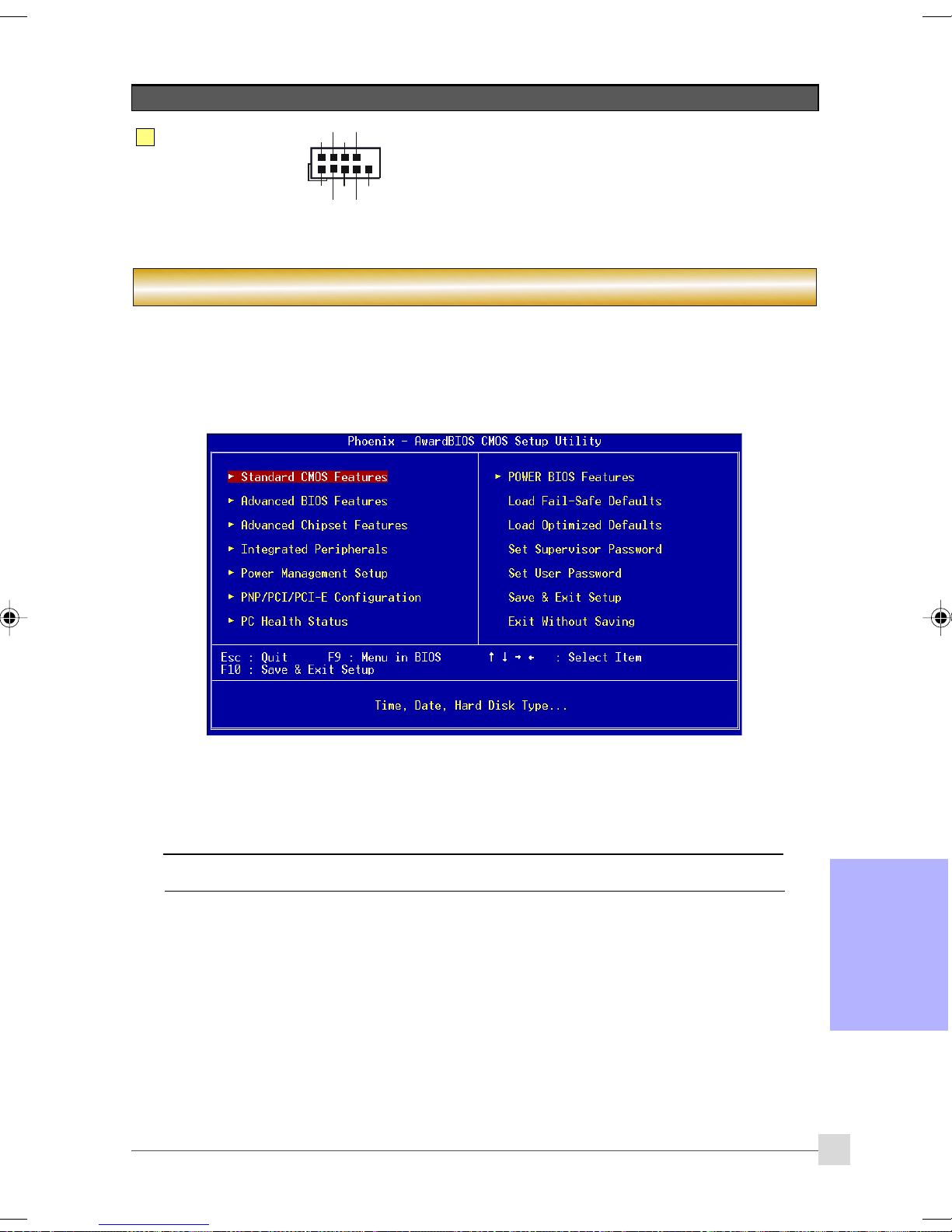
16
コネクタコネクタ
コネクタ
コネクタコネクタ
COM1
Installation
図図
図
図図
RTS
RI
DSR
CTS
TXD
DTR
10
9
Ground
2
1
DCD
RXD
説明説明
説明
説明説明
COM1:シリアルポートコネクタ
シリアルポートはモデム、シリアルプリンタ、リモート
ディスプレイ端末、その他のシリアルデバイスと共に使用
できます。
セクションセクション
セクション 3 -- BIOS
セクションセクション
セットアップセットアップ
BIOS
セットアップ
セットアップセットアップ
初めてコンピュータを起動するとき、BIOS CMOSセットアップユーティリティに入る必要があります。コン
ピュータの電源をオンにし、パワーオンセルフテスト(POST)の間に<Del>キーを押します。BIOS CMOSセット
アップユーティリティが図のように開きます。
セットアップセットアップ
セットアップ
セットアップセットアップ
< CMOS セットアップユーティリティ>
「ロード最適化デフォルト」ページを選択して、そのページに入ります。このページは出荷時設定をロードし
て、システムパフォーマンスを最適化します。簡単なオンスクリーンの指示に従って、この手順を完了してく
ださい。「ESC」を押すと終了し、「セットアップを保存して終了」を選択すると起動が続行されます。
BIOS
設定に関する詳細は、付属設定に関する詳細は、付属
設定に関する詳細は、付属
設定に関する詳細は、付属設定に関する詳細は、付属
CDCD
のマニュアル完全版を参照してください。のマニュアル完全版を参照してください。
CD
のマニュアル完全版を参照してください。
CDCD
のマニュアル完全版を参照してください。のマニュアル完全版を参照してください。
13
日本語日本語
日本語日本語
日本語
Page 90

Installation
セクションセクション
セクション4 --
セクションセクション
オペレーティングシステムがインストールされたら、メインボードのドライバをインストールする必要があり
ます。
Please Select:
方式1
方式2
付属のCDをCD-ROMにセットすると、メインメニュー画面が表示されます。メインメニューには、サポートされ
るドライバ、ユーティリティ、ソフトウェアへのリンクが表示されます。
Auto Installation
Manual Installation
Please install SP1 for Windows XP before installing nForce driver
>> nVIDIA nForce Driver
>> REALTEK High Definition Audio Driver
>> USB 2.0 Driver
>> JMicron PCI Express SATA II and PATA Controller Driver
>> AMD Cool’n’Quiet Processor Driver
ドライバおよびユーティリティドライバおよびユーティリティ
ドライバおよびユーティリティ
ドライバおよびユーティリティドライバおよびユーティリティ
方式方式
11
方式
1
方式方式
11
このアイテムは、すべてのドライバを自動的にインストールします。
方式方式
22
方式
2
方式方式
22
このアイテムでは、ドライバを選択してインストールできます。
ステップステップ
ステップ
ステップステップ
ステップステップ
ステップ
ステップステップ
ステップステップ
ステップ
ステップステップ
ステップステップ
ステップ
ステップステップ
ステップステップ
ステップ
ステップステップ
日本語
日本語日本語
日本語日本語
ドライバのインストールに成功すると、付属のユーティリティ・ソフトウェアのインストールに進めます。
1 :1 :
「「
1 :
「nVIDIA nForce Driver
1 :1 :
「「
2 :2 :
「「
2 :
「REALTEK High Definition Audio Driver
2 :2 :
「「
トールします。
3 :3 :
「「
3 :
「USB 2.0 Driver
3 :3 :
「「
44
「「
4 :
「JMicron PCI Express SATA II and PATA Controller Driver
44
「「
SATA IIとPATAコントローラドライバをインストールします。
55
「「
5 :
「AMD Cool’n’Quiet Processor Driver
5
5
「「
をインストールします。
メインメニューアイテムは購入したモデルによって異なることがあメインメニューアイテムは購入したモデルによって異なることがあ
メインメニューアイテムは購入したモデルによって異なることがあ
メインメニューアイテムは購入したモデルによって異なることがあメインメニューアイテムは購入したモデルによって異なることがあ
ります。ります。
ります。
ります。ります。
」」
」をクリックしてUSB 2.0ドライバをインストールします。
」」
」」
」をクリックしてチップセットドライバをインストールします。
」」
」」
」をクリックしてオーディオドライバをインス
」」
」」
」をクリックしてAMDシリーズプロセッサドライバ
」」
」」
」JMicron PCI Express
」」
14
Page 91

Installation
セクションセクション
セクション5 -- Ghost BIOS
セクションセクション
Ghost BIOSを使うと、通常はシステムが起動できないBIOSの破損状態から復帰できます。Ghost BIOSはBIOSを自
分で修理できるので、メインボードの修理を依頼する手間が省けます。
Ghost BIOSGhost BIOS
Ghost BIOS
Ghost BIOSGhost BIOS
1. 付属CDのThunder Flashユーティリティをインストールします。
2. このユーティリティを使ってBIOSリカバリー・ディスク (BRD) を作成します。
の準備の準備
の準備
の準備の準備
BIOS
1.Thunder Flash ユーティリティを実行します。
2. インターネットに接続します。
3. 空のフロッピー・ディスクをフロッピー・ドライブに入れて、「ロード(LOAD)」をクリックします。
4. 後で使用する場合に備えて、このフロッピーを安全な場所に保管します。
::
:
::
“LOAD”
リカバリー・ディスクの作成方法リカバリー・ディスクの作成方法
リカバリー・ディスクの作成方法
リカバリー・ディスクの作成方法リカバリー・ディスクの作成方法
::
:
::
BIOSBIOS
が破損した場合が破損した場合
BIOS
が破損した場合
BIOSBIOS
が破損した場合が破損した場合
BIOSに破損などの問題がある場合、システムを再起動すると、この画面が表示されます。作成済みのBRDフロッ
ピーまたは付属のドライバCDからBIOSを復元するよう選択できます。
1.BIOSリカバリー・ディスクのフロッピーから復元する場合は、作成済みのフロッピー・ディスクを挿
入して、「1」をクリックします。
2. メインボード・システムのドライバCDから復元する場合は、光学ドライブにドライバCDを挿入して、
「2」をクリックします。
システムのドライバCDを構成しているのはセーフ・モードのBIOSだけであることに注意
してください。復元後に正規のBIOSを更新してください。
::
:
::
日本語日本語
日本語日本語
日本語
15
Page 92

Installation
この画面が表示されると、BIOSバージョンが更新されていないことを意味します。BIOSの
更新については、Magic Flashステップを参照してください。
日本語
日本語日本語
日本語日本語
16
 Loading...