


FCC Information
This equipment has been tested and found to comply with the limits for a Class B digital device, pursuant to Part 15 of the FCC
Rules. These limits are designed to provide reasonable protection against harmful interference in a residential installation. This equipment
generates radio frequency energy, and if not installed and used in accordance with the instructions, may cause harmful interference to radio
or television reception, which can be determined by turning the equipment off and on. The user is encouraged to try to correct the
interference by one or more of the following measures:
• Reorient the receiving antenna.
• Increase the separation between the equipment and receiver.
• Connecting the equipment to an outlet on a circuit different from that to which the receiver is connected.
• Consult the dealer or an experienced radio/TV technician for help.
This device complies with Part 15 of FCC Rules. Operation is subject to the following two conditions:
(1) This device may not cause harmful interference and
(2) This device must accept any interference received, including interference that may cause undesired operation.
Notice to user: Changes or modifications to this product not approved by the party responsible for FCC compliance could void your
authority to operate this equipment.
In order for an installation of this product to maintain compliance with the limits for a Class B device, shielded cables must be used for the
connection of any devices external to this product.
To the judgment of the products with regard to electromagnetic compatibility according following regulations:
EN 50081-1 (EN55022 class B)
EN 50082-1 (IEC 801 Part 2, 4 / ENV 50140 / ENV 50141)
91004099 1
Macrovision Information
This product incorporates copyright protection technology that is protected by U.S. patents and other intellectual
property rights. Use of this copyright protection technology must be authorized by Macrovision, and is intended
for home and other limited viewing uses only unless otherwise authorized by Macrovision. Reverse engineering
or disassembly is prohibited.
PNY Verto Graphic Card Warranty
Please refer to our website at www.pny.com or write to PNY Customer Service, 299 Webro Rd.
Parsippany, NJ 07054 for complete Warranty information.
The information in this document is subject to change without notice
2 91004099

Contents
CHAPTER 1 - INTRODUCTION.....................................................................................................................................4
CHAPTER 2 - HARDWARE INSTALLATIO N................................ ...........................................................................6
CHAPTER 3 - SOFTWARE INSTALLATION ..........................................................................................................16
CHAPTER 4 - DISPLAY PROPERTIES ......................................................................................................................22
CHAPTER 5 - NVIDIA® GPU PROPERTIES ...........................................................................................................24
CHAPTER 6 - NVIDIA® NVIEW™ INSTALLATION...........................................................................................39
CHAPTER 7 - TECHNICAL SUPPORT......................................................................................................................49
Limited Liability
The information contained in this manual has been validated at the time of manual production. The
manufacturer reserves the right to make any changes, additions and revisions to the product described in this
manual at any time and without notice. Consequently, PNY Technologies, Inc. assumes no liability for damages
incurred directly or indirectly from errors, omissions or discrepancies between the product and the manual.
Copyright
Copyright 2002-200 4 All rights reserved. No reproduction of this document in any form is permitted without
prior written authorization from PNY Technologies , Inc.
Trademarks
All registered trademarks are the property of their respective owners.
91004099 3
Chapter 1 - Introduction
Congratulations on the purchase of your graphics accelerator card by PNY Technologies Inc. You are now the
owner of a state-of-the-art video adapter that offers features and functionality beyond any other graphics card in
its class. We recommend that you read through the Installation Guide before installing your video card to
ensure that the installation process goes smoothly.
Package Contents:
Please check your VGA package, which contains the items below. If you find any damaged or missing items,
please contact your dealer.
• PNY GeForce™ graphics card
• This Installation Guide
• CD-ROM: nVidia® GeForce™ drivers for Microsoft® Windows® 98/Me/2000/XP/NT4.0, Microsoft®
DirectX® 8 and DirectX® 9, nVidia® demos, desktop wallpapers
• S-Video cable (If required by your PNY GeForce™ graphics card)
• HDTV-out breakout pod (If required by your PNY GeForce™ graphics card)
• Y power cable (If required by your PNY GeForce™ graphics card)
• DVI to VGA adapter (If required by your PNY GeForce™ graphics card)
4 91004099

Before You Begin
• Before installing the Display driver, make sure your Windows® 98/2000/ME/XP or NT was installed in
VGA mode and functions properly.
• To use an AGP graphics card with Windows® NT4.0, you may need to re-install NT with Service Pack 6
(SP6) before installing the AGP card.
• If you are running Windows® NT4.0, please note that some drivers are not compatible with earlier releases
of Windows® NT. Consult your dealer or local support to ensure you have the most recent releases for
Windows® NT and the drivers.
91004099 5
Chapter 2 - Hardware Installation
Static electricity can severely damage electronic parts. Take these precautions prior to beginning the
graphics card installation:
• Before touching any electronic parts, drain the static electricity from your body . You can do this by
touching the internal metal frame of your computer while it's unplugged.
• Don't remove a card from the anti-static container it shipped in until you're ready to install it . Whenever
you remove a card from your computer, always make sure to place it back in its container.
• Don't let your clothes touch any electronic parts.
• When handling a card, hold it by its edges, and avoid touching its circuitry.
Preparing Your Computer for Installation
Prior to working on your computer, make sure the power of the computer and any attached equipment such as a
monitor or printer is turned off. Unplug your computer and remove the cover. Remove your current graphics
card. For systems with ‘On-Board 3D Graphics’, there is no graphics card to remove. Some systems may
require you to disable your ‘On -Board 3D Graphics’. Consult your PC users’ manual or vendor manual on how
to properly do this.
6 91004099
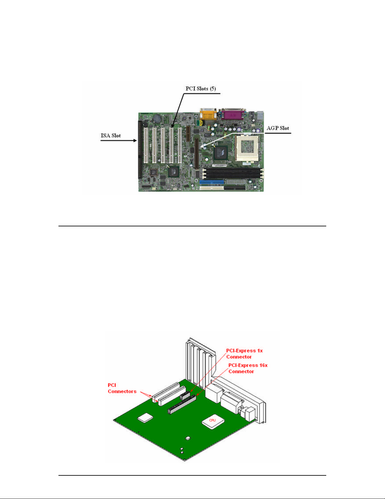
Selecting the Proper Expansion Slot
Most computers have a combination of AGP, PCI and ISA expansion slots. All these slots may look similar at
first; however you will notice their differences once you examine them more closely. The ISA connectors are
black and are the largest of the three types. The AGP slot on your computer motherboard is usually the closest
connector to the CPU and is made from a plastic of a contrasting brown color. The PCI connectors are usually
located between the AGP and ISA connectors, are made from a white plastic and are the same connector type
that most Sound or Modem Cards are connected. If you are still unsure which connectors are AGP and PCI,
consult your system manual to help you identify them. Plugging your graphics card into an i ncorrect slot could
damage the card, your computer, or both. Do not try to force a card into a slot that does not accommodate it, as
it is probably the wrong slot. The diagram below should help you in identifying the proper slot.
Figure 1: Motherboard Example
91004099 7
PCI Express (PCI-E) Expansion Slot
Most PCI Express motherboards have a combination of PCI-E and regular PCI expansion slots. The PCI
connectors are usually located at the bottom of the motherboard and are usually made from a white plastic. This
is the same connector type where most Sound or Modem Cards are connected. The PCI-E connectors are the
next set of connectors adjacent to the PCI. Typically, motherboards have one or more of PCI-E 1x and PCI-E
16x slots. Your GeForce PCI Express graphics card will fit in the PCI-E 16x slot. If you are still unsure which
connectors are PCI-E and PCI, consult your system manual to help you identify them. Plugging your graphics
card into an incorrect slot could damage the card, your computer, or both. Do not try to force a card into a slot
that does not accommodate it, as it is probably the wrong slot. The diagram below should help you in
identifying the proper slot.
Figure 2: PCI-E Motherboard Example
8 91004099

Recognizing Your Graphics Card’s Connector Type
The following picture shows the three current available connectors for your graphics cards. You can see the
AGP, PCI and PCI-Express 16x connectors. Make note of the position of their notches as well as the connector
position relative to the bracket.
Figure 3: AGP vs. PCI vs. PCI-Express
91004099 9
Inserting Your Graphics Card
Remove the cover for the slot you intend to use and save the screw for the mounting bracket of your new PNY
graphics card. Then, position the PNY graphics card over the expansion slot that coincides with the type (AGP,
PCI, or PCI-Express 16x) of card purchased. Push the card firmly and evenly until it’s fully seated into the slot.
Replace the screw to secure the bracket of the graphics card to the computer chassis. Replace the cover of your
computer.
Figure 4: Inserting your graphics card.
10 91004099
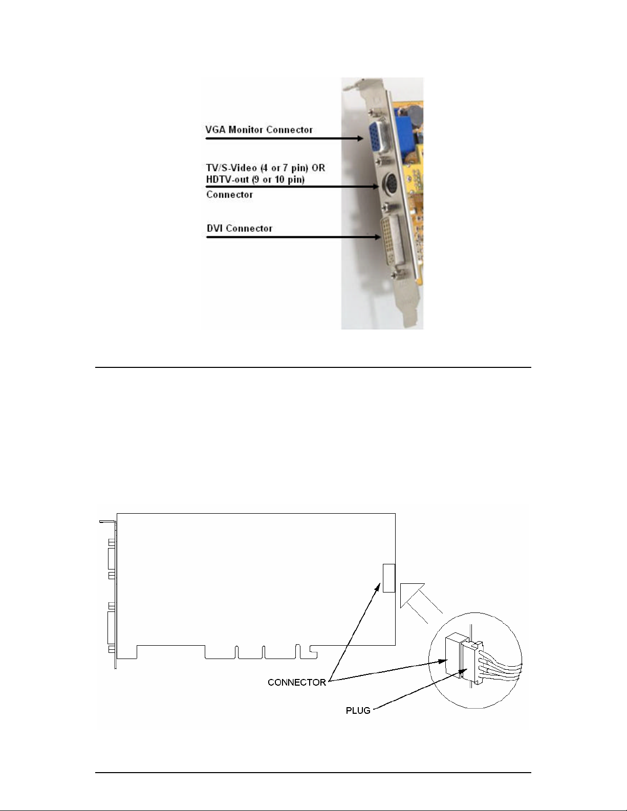
Connecting Your Display
Plug your Monitor, Flat Panel Display, or your S-Video (TV) cable into the appropriate connector on your
graphics card. Please note that if your card is equipped with HDTV-out, there is a 10pin connector instead of
the 4 or 7 pin connector for S-Video. All cables MUST be connected before your computer is powered on.
Figure 5: Possible graphics card connectors
91004099 11
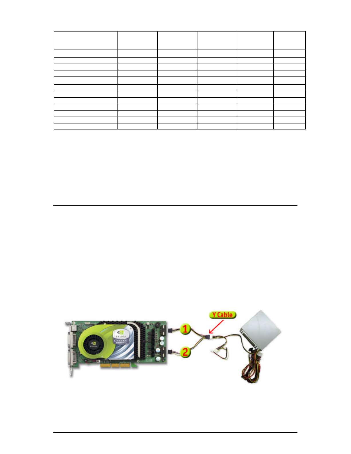
Additional Power Requirements (Single Additional Power Connector)
If your PNY GeForce™ graphics card is equipped with a single additional power connector, your system’s
power supply must be connected to it for the graphics card to work optimally. Locate an unused 4-pin (6-pin
for PCI-E cards) power plug inside your computer system and plug it into the card connector as shown below.
The power connector is keyed so that it can only be inserted one way. Please verify the orientation of the plug
before insertion. DO NOT FORCE THE POWER PLUG INTO THE CONNECTOR.
Figure 6: Additional power requirements for cards with one additional power connector
12 91004099
Minimum System Requirements
The following table outlines the minimum system requirements for your PNY GeForce™ graphics card.
Graphics
Card
System Power
Supply
AGP
Compliant 1
Motherboard
GF 6800 Ultra PCI-E 350W No
PCI-E
Compliant
Motherboard
Yes
Number of
Slots 2
2 Yes
Power
Dongle 3
GF 6800 GT PCI-E 350W No Yes 1 Yes
GF 6600 GT 350W No Yes 1 No
GF 6600 350W No Yes 1 No
GF 6800 Ultra AGP 4 350W Yes 5
No
2 Yes 6
GF 6800 GT AGP 350W Yes 5 No 1 Yes
GF 6800 300W Yes 5 No 1 Yes
GF 6600 GT AGP 350W Yes No 1 Yes
FX 5500 AGP 250W Yes No 1 No
FX 5500 PCI 250W No No 1 No
All Other AGP 250W Yes No 1 No
All Other PCI 250W No No 1 No
Notes:
1. An AGP compliant motherboard. Some motherboards violate the AGP specification and therefore this card may not physically fit in
some systems.
2. If two (2), a vacant PCI slot adjacent to the AGP slot is required . This board occupies two slots: one AGP and one PCI.
3. An available hard disk drive power dongle (smaller floppy disk drive connector is not sufficient).
4. This card has special power enhancements. See the following section for details.
5. These cards do not support AGP 1X or 2X.
6. These cards require two power dongles.
91004099 13
Connecting GeForce™ 6800 Ultra AGP to a Power Supply
The GeForce™ 6800 Ultra AGP requires a stable, 12-volt power source for best performance, reliability, and
enjoyment. For GeForce™ 6800-based graphics cards, NVIDIA recommends a power supply with a rating of
350W or higher. To automatically enhance your GeForce™ 6800 Ultra AGP for maximum performance,
NVIDIA recommends a higher rated power supply.
GeForce™ 6800 Ultra AGP boards will have two standard disk drive power plugs on the back end of the card.
Both power connectors must be connected for normal use. You may use a Y-cable (see Figure 7) or connect
two dongles off of the same power cable if plugs are short for normal use (see Figure 8). To automatically
enhance your card’s performance, you should attach two independent (not shared or split with a y-cable) hard
disk drive power dongles from the system’s power supply to these plugs (see Figure 9).
Figure 7: Power configurations for normal use of the GeForce™ 6800 Ultra AGP (Using Y Cable).
14 91004099
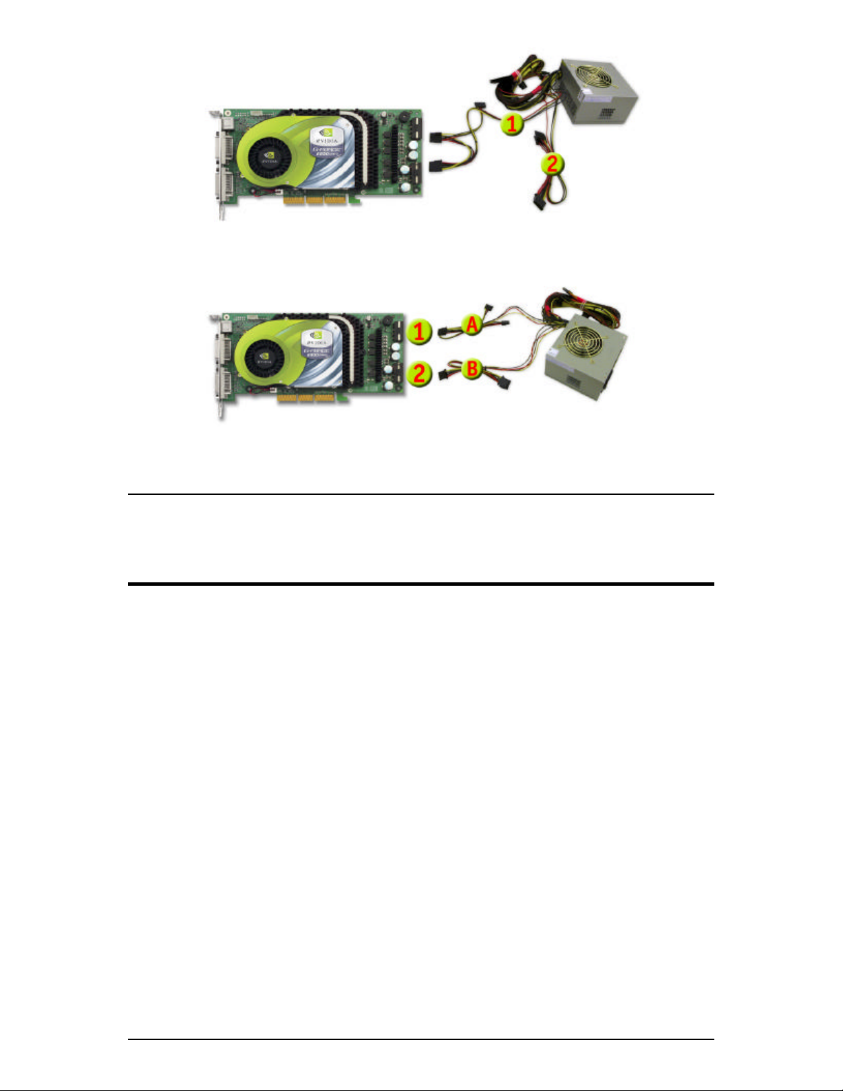
Figure 8: Power configurations for normal use of the GeForce™ 6800 Ultra AGP (Using 2 dongles of f of
same power cable).
Figure 9: Recommended power configurations for automatically enhance the GeForce™ 6800 Ultra AGP
(Using two separate power cables).
91004099 15
Chapter 3 - Software Installation
Installing the Standard Graphics Adapter (VGA) Driver
• Power up you computer and launch Windows® 98/2000/Me/XP/NT
• The Building Driver Database dialog box will appear as the Windows® operating system builds the driver
database
• When the Add New Hardware Wizard appears, click Next
• Choose Search For The Best Driver For Your Device, and click Next
• Make sure that all of the four choices are left blank. If not, un-check the applicable box. Then click Next
• Windows® is now ready to install the Standard Graphics Adapter driver. Click Next to continue
• Click Finish. Windows® will install the Standard Graphics Adapter driver
• You will now be prompted to re-start your computer. Click Yes
You are now ready to install the required drivers for your new graphics card
Installing DirectX® 9
GeForce™ FX graphics cards have been designed with full support for Microsoft® DirectX® 9. In order to
take advantage of these new capabilities and enhancements, you need to install DirectX® 9 before installing the
drivers for your graphics card.
Note: Some games may not be compatible with DirectX® 9. Please verify your games’ manuals for
compatibility or go to the games manufacturers’ website for any upgrades or patches. If your
game is not compatible, you may need to install DirectX® 8.1. See Installing DirectX® 8.1.
16 91004099

Steps to follow:
1. Turn on your computer and start Windows®
98/2000/Me/XP/NT.
2. Insert the Driver CD into your CD-ROM drive.
3. The ‘Auto-load’ install shield will appear as
shown in Figure 10, click on the Install
DirectX® 9 button.
a. If your CD-ROM drive is not auto-detect
enabled, click the Start button on the task
bar and then select the Run button.
b. Type “D:\launch.exe” in the dialog box
and hit enter (where D:\ is the location of
your CD-ROM drive).
c. The install shield will now appear.
Proceed with step 3 above.
4. DirectX® 9 will now be installed in your
system, follow the instructions on the screen to
complete installation.
5. Your system will restart to complete the
installation.
6. You may now proceed to Installing
GeForce™ Drivers.
Figure 10: PNY Software Installation CD
91004099 17
Installing GeForce™ Drivers
After installing DirectX® 9 (or DirectX® 8.1), the
drivers for your graphics card must be installed. To
install the drivers follow these steps:
1. When your system restarts, the ‘Auto-load’
install shield will appear, click on the Install
Drivers button.
a. If your CD-ROM drive is not auto-detect
enabled, click the Start button on the task
bar and then select the Run button.
b. Type “D:\launch.exe” in the dialog box
and hit enter ( where D:\ is the location of
your CD-ROM drive).
c. The install shield will now appear.
Proceed with step 1 above.
2. The VGA Installation dialog box will appear on
the screen, follow the instructions on the screen
to complete installation.
a. If you have upgraded your graphics
card from another nVidia® based card,
your system will have older nVidia®
drivers installed and you will get the
splash screen as shown in Figure 11.
b. It is recommended that you
Figure 11: Uninstall Existing Drivers Splash Screen
uninstall the nVidia® drivers in
your system in order for the new
drivers to install properly.
18 91004099

c. To do this, click the Uninstall
Existing Drivers button.
d. The existing drivers will be uninstalled
and your system will be rebooted.
e. Once your system reboots, proceed
with step 1 above.
3. At the time of shipment, the compatibility
testing of the graphics card drivers may not
have completed. If this is the case, you will get
a warning as in Figure 12. Please click
Continue anyway.
a. To check for the latest drivers, go to
our website at:
http://www.pny.com/support
4. Once the drivers are installed, the InstallShield
Wizard Complete window will appear as shown
in Figure 13.
5. Verify that Yes is selected and then click on
Finish to restart your system for the changes to
take effect.
Figure 12: WHQL warning
Figure 13: Restart your system
91004099 19
Installing DirectX® 8.1
If your games do not support DirectX® 9, you may install DirectX® 8.1.
To install follow these steps:
1. Turn on your computer and start Windows® 98/2000/Me/XP/NT
2. Insert the Driver CD into your CD-ROM drive
3. The ‘Auto-load’ install shield will appear as shown in Figure 10, click on the Install DirectX® 8.1 button.
a. If your CD -ROM drive is not auto-detect enabled, click the Start button on the task bar and
then select the Run button.
b. Type “D:\launch.exe” in the dialog box and hit enter (where D:\ is the location of your CD-
ROM drive).
c. The install shield will now appear. Proceed with step 3 above.
4. DirectX® 8.1 will now be installed in your system, follow the instructions on the screen to complete
installation.
5. Your system will restart to complete the installation.
6. You may now proceed to Installing GeForce™ Drivers.
20 91004099

Installing nVidia® WDM Drivers
If your PNY GeForce™ graphics card is equipped with Video-In -Video-Out (VIVO) functionality, you must
install the nVidia® WDM drivers for proper operation.
To install follow these steps:
1. Make sure that the GeForce™ Drivers have been already
installed. If not, proceed to Installing GeForce™
Drivers.
2. Turn on your computer and start Windows® 2000/XP
3. Insert the Driver CD into your CD-ROM drive
4. The ‘Auto-load’ install shield will appear as shown in
Figure 10, click on the Bonus Software button.
a. If your CD-ROM drive is not auto-detect
enabled, click the Start button on the task
bar and then select the Run button.
b. Type “D:\launch.exe” in the dialog box
and hit enter (where D:\ is the location of
your CD-ROM drive).
c. The install shield will now appear. Proceed
with step 4 above.
5. Click on the nVidia® WDM Drivers button and follow
the instructions on the screen to complete installation.
6. At the time of shipment, the compatibility testing of the
WDM drivers may not have completed. If this is the
case, you will get a warning similar to Figure 12. Please
click Continue anyway.
a. To check for the latest drivers, go to our
website at: http://www.pny.com/support
7. You will need to restart your system to complete the
installation.
Figure 14: WDM Installation
91004099 21
Chapter 4 - Display Properties
Color Quality and Screen Resolution
After completion of the display drivers, you are now ready to configure the display properties of your PNY
graphics card . To open the “Display Properties” window of your computer, you may simply right -click the
Windows® 98/2000/M e/XP or NT desktop wallpaper area and click on the “Properties” item to open it as
shown on Figure 15.
Figure 15: Opening the Display Properties Window
22 91004099

The Display Properties w indow will appear on your screen. Click on the settings tab to see your current screen
resolution and color quality as shown on Figure 16.
Screen resolution: Displays the current screen
resolution settings for the monitor that appears in
Display. Drag the slider to specify the screen
resolution you want. As you increase the number of
pixels, you display more information on your screen,
but the information decreases in size. Verify your
monitor’s capabilities before changing.
Color Quality: Displays the current color quality for
the monitor. To use a different color setting, click the
arrow, and then click the setting y ou want.
Advanced: Click on this button to open up the video
card’s advanced options window where you can
“tweak” the performance of your video card. See
Chapter 5 - NVIDIA® GPU Properties for more
information.
Figure 16: Display Properties Window
91004099 23
Chapter 5 - NVIDIA® GPU Properties
New exciting technologies are here. The combination of the following two technologies will greatly improve
your system’s graphics performance. Please visit www.pny.com for the latest SLI ready PNY GeForce™ PCI
Express offerings.
Figure 17: PCI Express
PCI Express is a brand new high -performance technology for PCs. With double the bandwidth of the AGP 8X
graphics bus, PNY GeForce™ PCI Express solutions deliver a new level of PC performance for graphics. PCI
Express solutions provide something for every type of PC user; delivering faster graphics and system
performance for your PC.
24 91004099

Figure 18: SLI™ Technology
NVIDIA® SLI™ (Scalable Link Interface) is a revolutionary approach to combining multiple GPUs in a single
system to scale performance. This multi-GPU technology takes advantage of the increased bandwidth of the
PCI Express™ bus architecture and features intelligent hardware and software solutions that allow multiple
GPUs to efficiently work together to deliver earth-shattering performance.
91004099 25
In this section we will briefly go over the different capabilities th at you may find on your new graphics card.
The following screen shots were taken using a GeForce™ 6800 Ultra AGP graphics card in Windows® XP using two
DFPs (Digital Flat Panels) and nVidia driver release 61.34.
Graphics Card Information
Once the Advanced button is clicked on the Display
Properties window (see Figure 16), the advanced
features window opens. Click on the tab with the
graphics card name and you will see the information
as shown on Figure 19. Notice the small list that
opens up to the left of the window. You can click on
any one of the items to view its settings.
This screen displays graphics card adapter
information, system information and driver version
information.
Figure 19: Graphics Card Information
26 91004099

nView™ Display Mode
nView™ allows you to connect separate displays to a
single graphics card (if supported).
If you have a single monitor connected to the graphics
card, the Single display mode will be selected.
If you have multiple displays connected to the
graphics card, you will see multiple displays in the
middle of the window. From here you will be able to
select your preferred nView™ display mode.
The nView™ display modes available for multiple
monitor connections are Clone, Horizontal Span,
Vertical Span and Dualview
Figure 20: nView™ Display Mode
91004099 27
Performance and Quality Settings
This tab allows you to select the performance setting
for quality enhancements in Direct3D and OpenGL
applications.
The performance and quality settings can be
performed for individual applications (use the
Application profiles drop-down menu) or globally
for all applications (default).
Figure 21: Performance and Quality Settings
28 91004099

Color Correction
This tab allows you to modify the colors as displayed
by your PNY Graphics Card. You can choose one of
the available color profiles to best meet your
requirements.
• Standard Mode: Allows you to specify color
correction settings using the Brightness, Contrast
and Gamma sliders
• Advanced Mode: Allows you to specify color
correction settings by manually inserting,
dragging and removing control points along the
curve shown in the graph
• ICC Profile Mode: Uses the color correction
curves imported from the specified ICC profile
Figure 22: Color Correction
91004099 29
Overlay Controls
Use these controls to adjust the q uality of video or
DVD playback on your monitor.
• Select screen region to zoom: To select the area
of the video screen that you want to zoom, click
the center or arrow icons. Once selected, you can
zoom to that portion of the screen by moving the
zoom slider.
• Zoom control: This lets you scale the rendered
video. The Video Overlay option sets the zoom
selection to the primary display on which the
overlay video is rendered.
• Overlay color controls : Use these control to
adjust the quality of video or DVD playback on
your monitor. Pressing the Adjust Colors button
will bring you to the Color Correction tab.
Figure 23: Overlay Controls
30 91004099

Full Screen Video
This tab allows you to set your video overlay controls.
• Select screen region to zoom: To select the area
of the video screen that you want to zoom, click
the center or arrow icons. Once selected, you can
zoom to that portion of the screen by moving the
zoom slider.
• Zoom control lets you zoom into the rendered
video. Click the drop-down menu button to select
the display zoom (Full screen video controls
must be in Auto-select mode)
o Video Mirror sets the zoom selection to
the secondary display on which the
video mirror is rendered.
o Both applies to the zoom selection to
both the primary and secondary display
on which the video is rendered.
• Full screen video controls : Use the Auto-select
option to automatically select any monitor, which
is not currently playing video in a window
(hardware overlay), to play video in full-screen
mode. To disable full-screen mode, select
Disable.
Figure 24: Full Screen Video
91004099 31
Troubleshooting
• Display the nVidia Settings icon to the
Windows taskbar
o Lets you apply any of the custom
Direct3D, OpenGL or color settings “on
the fly” from a convenient pop -up menu.
o The menu also contains items for
restoring default settings and accessing
the Display Properties dialog box.
• My connected TV is not being detected
o Forces the detection of a TV connected
to the graphics card, even thought he
control panel does not show that one is
currently connected.
o To enable TV settings
§ Select the check box and click
Apply
§ Restart your computer when
prompted. Once you log back
in, you can use the TV controls.
Figure 25: Troubleshooting
32 91004099

Temperature Settings
If your graphics card is equipped with a temperature
sensor, you will be able to see the current temperature
of the nVidia® GPU based graphics card installed in
your system.
This window also displays the ambient temperature of
surrounding the GPU in your system. This
temperature varies with other heat sources located
near the GPU.
Core Slowdown Threshold: This is the value at
which the nVidia GPU will slow itself down to
prevent overheating.
When this value matches the nVidia GPU Core
Temperature value and the Enable Heat Indicator
warning… option is enabled on this panel, a dialog
box will automatically appear warning of the
condition and the actions that have been taken to
prevent possible overheating and damage to any
particular GPUs in your system.
Figure 26: Temperature Settings
91004099 33
Refresh Rate Overrides
Allows the application to select its own refresh rate.
The list box is disab led when this option is enabled.
Click ‘Override refresh rates’ to select refresh rate
overrides to be used in your applications. Once that is
done, the list box will enable you to individually
override refresh rates for each resolution.
Default means that the application’s refresh rat is
used. Any other value means to set the refresh rate to
the value for full-screen applications.
To override a refresh rate:
1. From the Refresh Rate column, click the word
Default on the line that contains the Resolution
for which you want to change the refresh rate. A
list of values appears.
2. Select a refresh rate and click Apply.
Figure 27: Refresh Rate Overrides
34 91004099

Change Resolution
Use this tab to change the Screen resolution, the
Color quality and Monitor settings for your graphics
card and your monitor from a single location. It is
recommended that the "Hide modes that this
monitor cannot support" option is checked.
From this location, you can also create and use
Custom resolutions and refresh rates.
Figure 28: Change Resolution
91004099 35
Desktop Management
The Desktop Manager allows you to load or unload
the nView™ Desktop Manager as well as controlling
whether or not it loads automatically at system
startup.
The nView™ Desktop Manager wizard helps set up
the most commonly used nView™ display settings
including window management, desktop management
and “transparency” effects.
The Display wizard helps set up the most commonly
used nView™ display modes including screen
resolution and output type.
By clicking on the plus sign next to the Desktop
Management you can individually set the items
highlighted by the r ed square. The nView™ Desktop
Manager must be enabled.
36 91004099
Figure 29: Desktop Management

NVRotate
This utility lets you rotate the desktop:
• Landscape is the default
• Portrait rotates the desktop 90 degrees
• Invert ed Landscape rotates the desktop 180
degrees
• Inverted Portrait rotates the desktop 270 degrees
Single display mode is required.
Figure 30: NVRotate
91004099 37
Screen Menus
This tab allows you to customize the menu options
available on the nVidia driver options highlighted in
the red box.
Just drag the menu options you do not want to use into
the blue box. Enable screen menu editing must be
checked.
Figure 31: Screen Menus
38 91004099

Chapter 6 - nVidia® nView™ Installation
What is NVidia® nView ™?
NVidia’s nView™ is a desktop utility designed to give you an easier way of managing multiple displays and
enhancing your desktop. Once you install the nVidia® drivers and reboot, the follow ing nVidia® nView™
wizard will come up. You can either choose to configure it or cancel the nView™ setup. Follow the
instructions on the screen to complete installation.
For a full description of nView’s features and capabilities, go to http://www.pny.com/support/ and
download the nView™ Users Guide
Over the next few pages we will display the different screenshots of enabling nView™ in your system.
91004099 39
Figure 32: Enable Desktop Manager
Figure 33: nView™ Desktop Manager Setup Wizard
Click the Enable button and then click on the Setup
Wizard… button.
40 91004099
Read the welcome screen and click on Next to continue the
configuration or Cancel to exit.

Figure 34: nView™ Profiles
Figure 35: nView™ Window Management
Read about how to load and use a profile. If you wish,
choose a profile to load every time Windows® starts by
clicking on a profile from the list. Click on Next to
continue the configuration or Cancel to exit.
91004099 41
Read about customizing your windows and taskbar. If you
wish, enable this option by clicking on the radio buttons.
Click on Next to continue the configuration or Cancel to
exit. Horizontal Span setup required.
Figure 36: nView™ Window Management continued
Read about repositioning dialog boxes. If you wish,
enable repositioning by clicking on the radio button.
Click on Next to continue the configuration or Cancel
Figure 37: nView™ Desktop Management
Read about enabling nView™ menus. If you wish, enable
this option by clicking on the radio buttons. Click on Next
to continue the configuration or Cancel to exit.
to exit. Horizontal Span setup required.
42 91004099

Figure 38: nView™ Transparency
Figure 39: nView™ Finish
Read about enabling transparency. If you wish, enable
transparency by clicking on the radio button. Click on
Click on Finish to finalize the configuration or Cancel to
exit.
Next to continue the configuration or Cancel to exit.
91004099 43
Additional nView™ Settings:
Figure 40: Loading and Saving Profiles
In this area you can Load, Edit, Save, Delete or Create
new profiles to fit your needs.
Figure 41: Multi-Display Window Control
In this area you can configure the way your
application windows behave if you have multiple
monitors connected to your system.
44 91004099

Figure 42: nView™ Custom Application Settings
Figure 43: Setting Additional Desktops
In this area you can configure the nView™ behaves
In this area you can configure additional desktops.
with your applications.
91004099 45
Figure 44: Setting Window Effects
In this area you can configure the way your windows
behave.
46 91004099
In this area you can configure the way your windows
behave.
Figure 45: Setting Window Effects

Figure 46: Setting Zoom Functions
Figure 47: Setting Hot Keys
In this area you can configure the way the system
zooms into objects or text.
91004099 47
In this area you can configure the way the system
zooms into objects or text.
Figure 48: Mouse Settings
Figure 49: Enabling Tools
In this area you can configure special mouse abilities. In this area you can enable nVidia provided tools.
48 91004099

Chapter 7 - Technical Support
PNY Technologies provides ‘Live Technical Support’ 5 days a week from 9am to 8pm Monday thru Friday
Eastern Standard Time. Our Automated Technical Support System is designed to provide help with common
day-to-day graphics card issues . It is available 24 hours a day, 7 days a week at 1-888-316-1193.
For additional help you may visit the PNY Technical Support website http://www.pny.com/support/
91004099 49
 Loading...