

Page 1

QuicQuic
Quic
QuicQuic
QuicQuic
Quic
QuicQuic
nVnV
idia GeFidia GeF
nV
idia GeF
nVnV
idia GeFidia GeF
ff
or or
AMD SocAMD Soc
f
or
AMD Soc
ff
or or
AMD SocAMD Soc
TRADEMARK
All products and company names are trademarks or registered
trademarks of their respective holders.
k User’k User’
k User’
k User’k User’
k User’k User’
k User’
k User’k User’
GuideGuide
Guide
GuideGuide
GuideGuide
Guide
GuideGuide
oror
ce 6100 mainboarce 6100 mainboar
or
ce 6100 mainboar
oror
ce 6100 mainboarce 6100 mainboar
kk
et 754 pret 754 pr
k
et 754 pr
kk
et 754 pret 754 pr
ocessorocessor
ocessor
ocessorocessor
ss
s
ss
ss
s
ss
dd
d
dd
These specifications are subject to change without notice.
60000028GF610
Manual Revision 1.0
December 30, 2005
Page 2
English
DISCLAIMER OF WARRANTIES:
THERE ARE NO WARRANTIES WHICH EXTEND BEYOND THE
DESCRIPTION ON THE FACE OF THE MANUFACTURER LIMITED
WARRANTY. THE MANUFACTURER EXPRESSLY EXCLUDES ALL
OTHER WARRANTIES, EXPRESS OR IMPLIED, REGARDING ITS
PRODUCTS; INCLUDING ANY IMPLIED WARRANTIES OF
MERCHANTABILITY, FITNESS FOR A PARTICULAR PURPOSE OR
NONINFRINGEMENT. THIS DISCLAIMER OF WARRANTIES SHALL
APPLY TO THE EXTENT ALLOWED UNDER LOCAL LAWS IN THE
COUNTRY PURCHASED IN WHICH LOCAL LAWS DO NOT ALLOW OR
LIMIT THE EXCLUSION OF THE IMPLIED WARRANTIES.
HANDLING PROCEDURES:
Static electricity can severely damage your equipment. Handle the mainboard and
any other device in your system with extreme care and avoid unnecessary contact
with system components on the mainboard. Always work on an antistatic surface
to avoid possible damage to the mainboard from static discharge. Always have the
power supply unplugged and powered off when inserting and removing devices
within the computer chassis. The Manufacturer assumes no responsibility for any
damage to the mainboard that results from failure to follow instruction or failure to
observe safety precautions.
CAUTION
The mainboard is subject to damage by static
electricity. Always observe the handling procedures.
2
Page 3

1. Specification
Processor Support
Support Socket-754 based AMD Sempron/Athlon-64 up to 3700+ with 1.6GTs
Hyper Transport processors
Chipset
nVidia GeForce 6100 Chipset (GeForce 6100 + nForce 410)
Integrate GeForce6-class Texture engine, Support Microsoft DirectX 9.0c, Shader
Model 3.0 Graphics Processing Unit, 300MHz RAMDAC for display resolutions up
to and including 1920 x 1440 at 75 Hz
Main Memory
Two 184-pin DDR SDRAM DIMM sockets
Support single-sided or double-sided 2.5v DDR-266/333/400 DIMMs in 128/256/
512Mb technologies
Support up to 2GB memory size
Expansion Slots
Two PCI connectors compliant with PCI v2.3
One PCI-E (x1) connectors compliant with PCI Express 1.0a
One PCI-E (x16) connectors compliant with PCI Express 1.0a
USB
Eight USB connectors compliant with USB2.0 from embedded USB controller
(4 connectors at rear panel)
English
P-ATA IDE
Two IDE interface (up to 4 IDE devices) with UDMA-33/66/100/133 support
from embedded IDE controller
S-ATA II RAID
Two S-ATA II ports with up to 300MB/s bandwidth, support RAID 0, 1
LAN
One 10/100 Ethernet from onboard Realtek RTL8201 LAN PHY
I/O
Fintek LPC IO controller with PS/2 keyboard&mouse, floppy, printer, serial and
IrDA (v1.0 compliant)
Support Hardware Monitoring for fan speed monitoring, CPU/System temperature
IIntelligent fan speed control for CPU-fan (PWM) for quiet operation
3
Page 4

English
Audio
Onboard Realtek ALC-655 selectable 2 or 6-CH audio CODEC
- AC’97 v2.3 compliant
- Supports CD-In, Aux-In
- Supports automatic “jack-sensing”
- Rear panel audio jacks configuration:
roloCkcaJoiduA
eulBthgiLni-eniLtuo-oeretsraeR
emiLtuo-eniLtuo-oeretstnorF
kniPni-ciMrefoowbuS&retneC
BIOS
Flash EEPROM with Award Plug & Play BIOS
Support ACPI S3 (Suspend To RAM) mode in ACPI compliant O/S
Support EZ Boot for fast bootable device selection
Support Magic Health for system hardware status report during system boot-up
Special Features
Support KBPO function – Keyboard power on, turn on the computer from keyboard
Support Wake-On-LAN by PME
lennahc2 lennahc6
Support USB resume in S3
PowerBIOS for excellent overclocking features:
- Programmable FSB and PCI-E Clock output frequency with 1MHz fine tuning
- Support BIOS adjustable CPU multiplier, FSB clock, PCI-E x16 clock, DIMM
frequency
- Support BIOS adjustable CPU Core voltage, Chipset voltage, DIMM voltage
settings
Form Factor
245mm x 225mm Micro-ATX size
4
Page 5
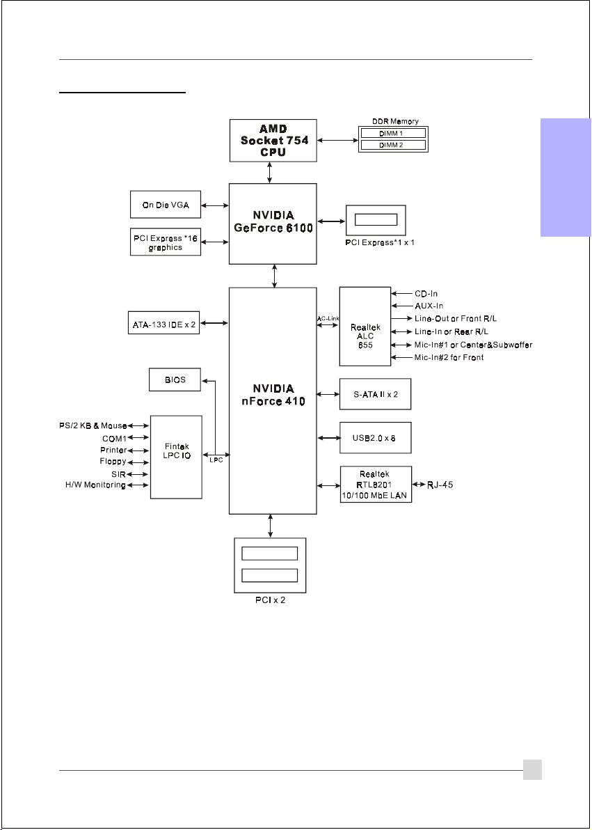
1.2 Block Diagram
English
5
Page 6

2. Setting up the mainbaord
Before assembling the mainboard into the PC case we recommend you to do the following:
1. CPU Installation
English
2. DDR Memory Insertion
After the mainboard is fitted into the case, you may
3. Install Add-on VGA or PCI cards
4. Connect the internal cables and wires
5. Connect your external peripherals to the rear I/O port
3. Installation
3.1 CPU Installation
Step 1
Open the socket by raising the actuation
lever.
The CPU is keyed to prevent incorrect insertion, do not
force the CPU into the socket. If it does not go in easily,
check for mis-orientation.
6
Step 2
1) Align pin 1 on the CPU with pin 1 on the
CPU socket as shown above. Insert the
CPU and make sure it is fully inserted into
the socket.
2) Close the socket by lowering and locking
the actuation lever.
Page 7

English
Step 3
Insert the heatsink as shown above.
Press the clips in the direction of the
arrows shown above to secure the
assembly to the CPU socket.
• Thermal compound and qualified heatsink recommended by AMD are a must to
avoid CPU overheat damage.
• Apply heatsink thermal compound/paste to the CPU.
Step 4
Plug the CPU fan power into the
mainboard’s CPU fan connector.
The installation is complete.
7
Page 8

3.2 DDR Memory Inser tion
The mainboard accommodates two 184-pin DIMMs (Dual In-line Memory Modules):
• Supports up to 2.0GB of 266/333/400MHz DDR SDRAM.
English
• Supports DRAM configurations defined in the JEDEC DDR DIMM specification.
Memory configurations supported:
oNtolSMMID1sMMID2
1#MMIDSS/SDSS/SD
2#MMIDSS/SDSS/SD
* SS: Single-Sided DIMM, DS: Double-Sided DIMM
Memory Installation :
To install, align the notch on the DIMM module with the connector.
Press straight down as shown in the figure until the white clips close and the
module fits tightly into the DIMM socket.
Notch
8
Page 9

3.3 VGA and PCI card installation
This mainboard is equipped with on-chip graphics engine, you may connect a VGA monitor
directly to its rear port. However, if you need to install VGA card follow the steps below.
To install a VGA card into the VGA slot or a PCI expansion card:
1. Remove the bracket (on the PC case) for the slot you intend to use.
2. Firmly press down the card into the slot until it is completely seated. For an VGA card
ensure the VGA slot clicker is locked as shown in the picture below.
3. Secure the card's bracket to the PC case with a screw.
English
9
Page 10

3.4 Rear IO Port
PS/2
English
Mouse
PS/2
Keyboard
3.5 Internal Connectors
Parallel Port
COM1
1
4
VGA1
RJ-45
LAN
USB2.0 ports
Line-in/Rear out (Light blue)
Line-out/Front out (Lime)
Mic-in/Center&Subwoofer (Pink)
1
10
3
11
6
5
1
7
8
9
2
10
Page 11

Connectors Figure Descriptions
JCPU_FAN
1
JPWR_FAN
JSYS_FAN
FDD
2
IDE1
3
Primary IDE
IDE2
Secondary IDE
PW1
4
PW12
CPU / Power Fan Power Connectors
Control
Sense
Ground
+12V
JCPU_FAN: Connect the CPU fan to this
connector.
JPWR_FAN: Use this connector if you are installing
Ground
+12V
Sense
an additional fan in the unit.
English
JSYS_FAN: The chassis fan will provide adequate
airflow throughout the chassis to
prevent overheating the CPU.
Floppy Drive Connector
1
1
Primary/Secondary IDE Connector
Connects to the IDE device, i.e. HDD and CD-
ROM device.
When using two IDE drives on the
same connector, one must be set to
Master mode and the other to Slave
mode. Refer to your disk drive user’s
manual for details.
23
24
3.3V
+12V
+12V
4
3
+12V+12V
GroundGround
2
1
11
1
PW1: 24-pin ATX Power Connector
Ground
+5V
PW12: 4-pin ATX12V Power Connector
+5V
+5V5VSB
-5VPW-OK
The plugs of the power cables are designed to fit
GroundGround
Ground+5V
in only one orientation.
GroundGround
PS-ON+5V
GroundGround
-12V3.3V
3.3V3.3V
The PW1 and PW12 Power Connector
must be used simultaneously.
2
1
MIC_In
NC
Front Line-out-R
CFPA
5
Front Line-out-L
GND
+5V
Rear Line-out-FR
Key
Rear Line-out-FL
9
10
CFPA: Front Panel Audio Connector
This connector is used only if the speaker and
microphone needs to be plugged at the front of
the PC case. Otherwise, leave the jumpers at the
default position.
11
Page 12

Connectors Figure Descriptions
6
English
7
8
CD-IN
AUX-IN
CUSB3
CUSB4
CFP
CIR
1
CD_IN_Right
CD_Reference
CD_IN_Left
1
AUX_IN_Right
GND
AUX_IN_Left
CD-IN/AUX-IN: CD Audio-in connectors
These connectors are used to receive audio from a
CD-ROM drive, TV tuner or MPEG card.
CUSB3/CUSB4: Four USB2.0 header
This mainboard includes 4 additional onboard USB
ports.
To use these additional USB ports, a USB bracket
is required. Please contact your retailer for details.
CFP: Case Front Panel Connector
HD_LED
This LED indicates hard drive activity.
PWR_LED
Connects to the power indicator on the PC case.
RST
Connects to the RESET switch on the PC case.
PW_ON
Connects to the Power button on the PC case, to
turn on the system. To turn off the system,
press the power button for 4 seconds.
CIR: IR connector
For connection to an IrDA receiver unit.
12
9
10
CSPK
SATA1
SATA2
JCMOS
GND
B+
A+
GND
A-B-
GND
Settings:
1-2: Normal (Default)
2-3: Clear CMOS
CSPK: Speaker
Connects to the case’s speaker for PC beeps.
1
SATA1 ~ SATA2: Two Serial ATA II Connectors
These connectors enable you to connect Serial ATA
HDDs or optical drives type.
JCMOS: Clear CMOS data Jumper
This resets the BIOS CMOS data back to the
factory default values. Recommend to leave at
Normal (default) postion.
Page 13

Connectors Figure Descriptions
11
JUSB
Settings:
1-2: Enabled
2-3: Disabled
JUSB: USB S3 Wake up Jumper
This jumper disconnects 5V standby voltage to
USB devices. This means USB devices will not
be able to wake-up the system from S3 (Suspend
to RAM) power saving mode.
4. BIOS
BIOS Setup
When you start up the computer for the first time you need to enter the BIOS CMOS Setup
Utility. Power on the computer and press <Del> key during POST (Power On Self Test). The
BIOS CMOS SETUP UTILITY opens as shown below:
English
< CMOS Setup Utility>
Select and enter "Load Optimized Defaults" page. This page loads the factory settings for
optimal system performance. Follow the simple on-screen instructions to complete this
procedure. Press "ESC" to exit and select "Save & Exit Setup" to continue to boot.
For more information regarding BIOS settings refer to the complete manual in the
bundled CD.
13
Page 14

5. Driver Installation
Once the operating system has been installed, you need to install the drivers for the mainboard.
English
Please select:
Method 1
Method 2
Insert the bundled CD into the CD-ROM and the main menu screen will appear. The main
menu displays links to the supported drivers, utilities and software.
Method 1
This item installs all drivers automatically.
Auto Installation
Manual Installation
Please install SP1 for Windows XP before installing nForce driver
>> nVIDIA nForce Driver
>> nVIDIA DISPLAY Driver
>> AC’97 AUDIO Driver
>> USB 2.0 Driver
>> AMD Athlon 64 / AMD Sempron Series Processor Driver
Method 2
This item allows you to install the drivers selectively.
Step 1 : Click “nVIDIA nForce Driver” to install chipset driver.
Step 2 : Click “nVIDIA DISPLAY Driver” to install onboard graphics driver.
Step 3 : Click “AC’97 AUDIO Driver” to install audio driver.
Step 4 : Click “USB V2.0 Driver” to install USB 2.0 driver.
Step 5 : Click “AMD Athlon 64 / AMD Sempron Series Processor Driver” to
install AMD series processor driver.
14
Page 15

6. Flashing the BIOS
Do NOT flash the system BIOS unless it is really necessary.
Updating and flashing the BIOS content risks BIOS data corruption which may
cause system unable to power-on.
Download the xxxxx.EXE file corresponding to your model from our website to an empty direc-
tory on your hard disk or floppy. Run the downloaded xxxxx.EXE file and it will self extract.
Copy these extracted files to a bootable floppy disk.
Note: The floppy disk should contain NO device drivers or other programs.
1. Type “A:\AWDFLASH and press <Enter> Key.
2. You will see the following setup screen.
3. Please key in the xxxxx.bin BIOS file
name.
4. If you want to save the previous BIOS
data to the diskette, please key in [Y],
otherwise please key in [N].
XXXX
5. Key in File Name to save previous BIOS
to file.
XXXX
XXXXX
xxxxx.bin
xxxxx.bin
XXXX
XXXXX
xxxxx.bin
6. To confirm and proceed, please key in
[Y] to start the programming.
XXXX
XXXXX
xxxxx.bin
xxxxx.bin
English
7. The BIOS update is finished.
XXXX
F1 : Reset
XXXXX
xxxxx.bin
F10 : Exit
8. Keep this BIOS floppy disk for future use.
15
Page 16

English
16
 Loading...