

Page 1

User Guide
DGX-2 SYSTEM
DU-09130-001_v03 | November 2018
Page 2
TABLE OF CONTENTS
Introduction to the NVIDIA DGX-2 System .............................. 5
About this Document ................................................................................. 6
Hardware Overview .................................................................................. 6
Network Ports ....................................................................................... 11
Recommended Ports to Use for External Storage .............................................. 12
DGX OS Software ................................................................................... 13
Additional Documentation ......................................................................... 13
Customer Support .................................................................................. 14
Connecting to the DGX-2 Console ......................................... 15
Direct Connection ................................................................................... 16
Remote Connection through the BMC ........................................................... 17
SSH Connection ..................................................................................... 19
Setting Up the DGX-2 System ............................................... 20
Quick Start Instructions ...................................................... 24
Registration .......................................................................................... 24
Installation and Configuration..................................................................... 25
Obtaining an NVIDIA GPU Cloud Account ....................................................... 25
Getting Your NGC API Key and Selecting Container Tags for the Verification Examples . 25
Verifying Basic Functionality....................................................................... 26
Network Configuration ........................................................ 28
BMC Security ........................................................................................ 28
Configuring Network Proxies ...................................................................... 28
Configuring Docker IP Addresses ................................................................. 29
Opening Ports ....................................................................................... 31
Connectivity Requirements ........................................................................ 31
Configuring Static IP Address for the BMC ...................................................... 32
Configuring Static IP Addresses for the Network Ports ........................................ 36
Switching Between InfiniBand and Ethernet .................................................... 38
Configuring Storage – NFS Mount and Cache .......................... 44
Restoring the DGX-2 Software Image .................................... 46
Obtaining the DGX-2 Software ISO Image and Checksum File .............................. 47
Re-Imaging the System Remotely ................................................................ 47
Creating a Bootable Installation Medium ........................................................ 48
Re-Imaging the System From a USB Flash Drive............................................... 51
Retaining the RAID Partition While Installing the OS .......................................... 52
Updating the DGX OS Software ............................................. 54
Connectivity Requirements For Software Updates ............................................. 54
Update Instructions ................................................................................ 55
Updating Firmware ............................................................. 56
General Firmware Update Guidelines ............................................................ 56
Obtaining the Firmware Update Container ...................................................... 57
DGX-2 System User Guide ii
Page 3
Querying the Firmware Manifest ................................................................. 57
Querying the Currently Installed Firmware Versions .......................................... 57
Updating the Firmware ............................................................................. 58
Additional Options .................................................................................. 60
Command Summary ................................................................................ 61
Removing the Container ........................................................................... 61
Using the BMC ................................................................ 62
Connecting to the BMC .......................................................................... 62
Overview of BMC Controls ....................................................................... 63
Using DGX-2 System in KVM Mode ...................................... 66
Overview ........................................................................................... 66
Preliminary Setup - Converting the DGX-2 System to a DGX-2 KVM Host ............... 69
Launching a Guest GPU VM Instance .......................................................... 70
Stopping, Restarting, and Deleting a Guest GPU VM ........................................ 72
Connecting to Your Guest GPU VM ............................................................. 74
Managing Images ................................................................................. 76
Using the Guest OS Drives and Data Drives .................................................. 77
Updating the Software ........................................................................... 80
Supplemental Information ....................................................................... 82
Appendix A. Installing Software on Air-gapped DGX-2 Systems ................ 86
A.1. Installing NVIDIA DGX-2 Software ............................................................. 86
A.2. Re-Imaging the System .......................................................................... 87
A.3. Creating a Local Mirror of the NVIDIA and Canonical Repositories ........................ 87
A.4. Installing Docker Containers .................................................................... 88
Appendix B. Safety ............................................................................ 89
B.1. Safety Information ............................................................................... 89
B.2. Safety Warnings and Cautions .................................................................. 90
B.3.
B.4. Site
B.5.
B.6. Electrical Precautions ............................................................................. 92
B.7. System Access Warnings ........................................................................ 93
B.8. Rack Mount Warnings ............................................................................ 94
B.9. Electrostatic Discharge (ESD) .................................................................. 95
B.10. Other
Intended Application
Selection
Equipment Handling Practices
..................................................................................... 91
Hazards
Uses ..................................................................... 91
................................................................................. 95
................................................................ 91
Appendix C. Compliance ..................................................................... 97
C.1. United States ...................................................................................... 97
C.2. United States / Canada .......................................................................... 98
C.3. Canada ............................................................................................. 98
C.4. CE ................................................................................................... 98
C.5. Japan ............................................................................................... 99
C.6. Australia and New Zealand ..................................................................... 101
C.7. China .............................................................................................. 102
C.8. Israel .............................................................................................. 103
C.9. Russia/Kazakhstan/Belarus ..................................................................... 103
DGX-2 System User Guide iii
Page 4

C.10. Vietnam ........................................................................................ 103
C.11. South Korea ................................................................................... 104
C.12. Taiwan ......................................................................................... 107
DGX-2 System User Guide iv
Page 5
INTRODUCTION TO THE NVIDIA DGX-2
SYSTEM
The NVIDIA® DGX-2™ System is the world’s first two-petaFLOPS system that engages
16 fully interconnected GPUs for accelerated deep learning performance. The DGX-2
System is powered by NVIDIA® DGX™ software stack and an architecture designed for
Deep Learning, and High-Performance Computing and analytics.
DGX-2 System User Guide
5
Page 6
Introduction to the NVIDIA DGX-2 System
ID
Component
Qty
Description
ABOUT THIS DOCUMENT
This document is for users and administrators of the DGX-2 System. It is organized as
follows:
Chapters 1-4: Overview of the DGX-2 System, including basic first-time setup and
operation
Chapters 5-6: Network and storage configuration instructions.
Chapters 7-9: Software and firmware update instructions
Chapters 9: How to use the BMC
Chapter 10: How to configure and use the DGX-2 System as a Kernel Virtual Machine
host
HARDWARE OVERVIEW
1.2.1 Major Components
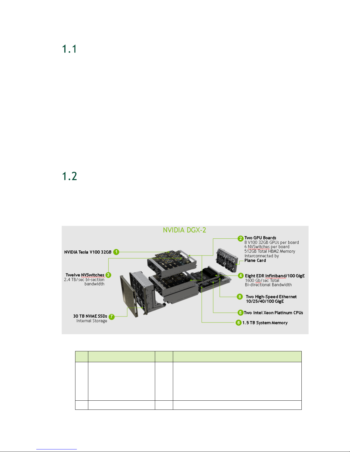
The following diagram shows the major components of the DGX-2 System.
1 GPU 16 NVIDIA® Tesla V100
- 2 petaFLOPS
- 512GB total GPU memory
- 81920 NVIDIA CUDA® Cores
- 10240 NVIDIA Tensor Cores
2 GPU Boards 2 Each board consists of
DGX-2 System User Guide
6
Page 7
Introduction to the NVIDIA DGX-2 System
8x NVIDIA® Tesla V100
Feature
Description
Each Power Supply
ID Component Qty Description
6x NVSwitches
512GB total HBM2 memory
3 NVSwitch 12 2.4 TB/s bi-section bandwidth
4 Network (cluster) 8 EDR Infiniband or 100 GbE
(1600 Gb/s total bi-directional bandwidth)
5 CPU 2 Dual Intel Xeon Platinum 8168, 2.7 GHz, 24-cores
6 System Memory 1.5 TB
7 Storage (RAID 0) (Cache) 8 3.84TB each (30TB total) NVMe SSDs
8 Network (storage) 2 High speed Ethernet 10/25/40/100 GbE
Can be expanded with the purchase and
installation of a second dual-port network
adapter.
1.2.2 Other Components not in Exploded View
Component Qty Description
Power Supply 6 3000 W each
Storage (RAID 1)
(OS)
2 960GB NVMe SSDs
1.2.3 Mechanical Specifications
Form Factor 10U Rackmount
Height 17.32” (440 mm)
Width 19" (482.6 mm)
Depth 31.3" (795 mm)
Gross Weight 360 lbs (163.29 kg)
1.2.4 Power Specifications
Input Specification for
200-240
volts AC
10 kW max. 3000 W @ 200-240 V,
16 A, 50-60 Hz
Comments
The DGX-2 System contains six loadbalancing power supplies.
DGX-2 System User Guide
7
Page 8
Introduction to the NVIDIA DGX-2 System
Feature
Description
1.2.5 Environmental Specifications
Operating Temperature
Relative Humidity
Airflow
Heat Output 34122 BTU/hr
5
◦ C to 35 ◦ C (41 ◦ F to 95 ◦ F)
20% to 85% noncondensing
1000 CFM @ 35
◦
C
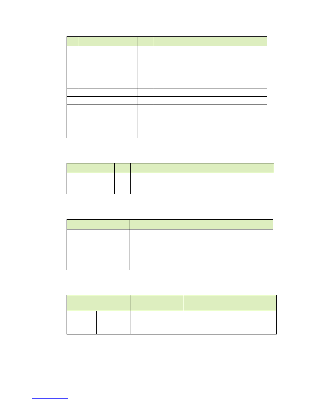
1.2.6 Front Panel Connections and Controls
ID Qty Description
1 4 Upper GPU tray fans
2 4 Lower GPU tray fans
3
4 2 Motherboard tray fans
5 1 Front console board:
6 1
DGX-2 System User Guide
8
(default)
Solid State Drives.
Additional SSDs available for purchase to expand to 16.
USB 3.0 (2x)
VGA (1x)
Power and ID buttons:
Top: Power button and LED
Press to turn the DGX-2 System on or off.
8
Page 9
Introduction to the NVIDIA DGX-2 System
Green steady: Power is On
ID Qty Description
Red steady: Power is Off
Red blinking: Status warning/error
Bottom: ID button
Press to cause an LED on the back of the unit to flash as an
identifier during servicing.
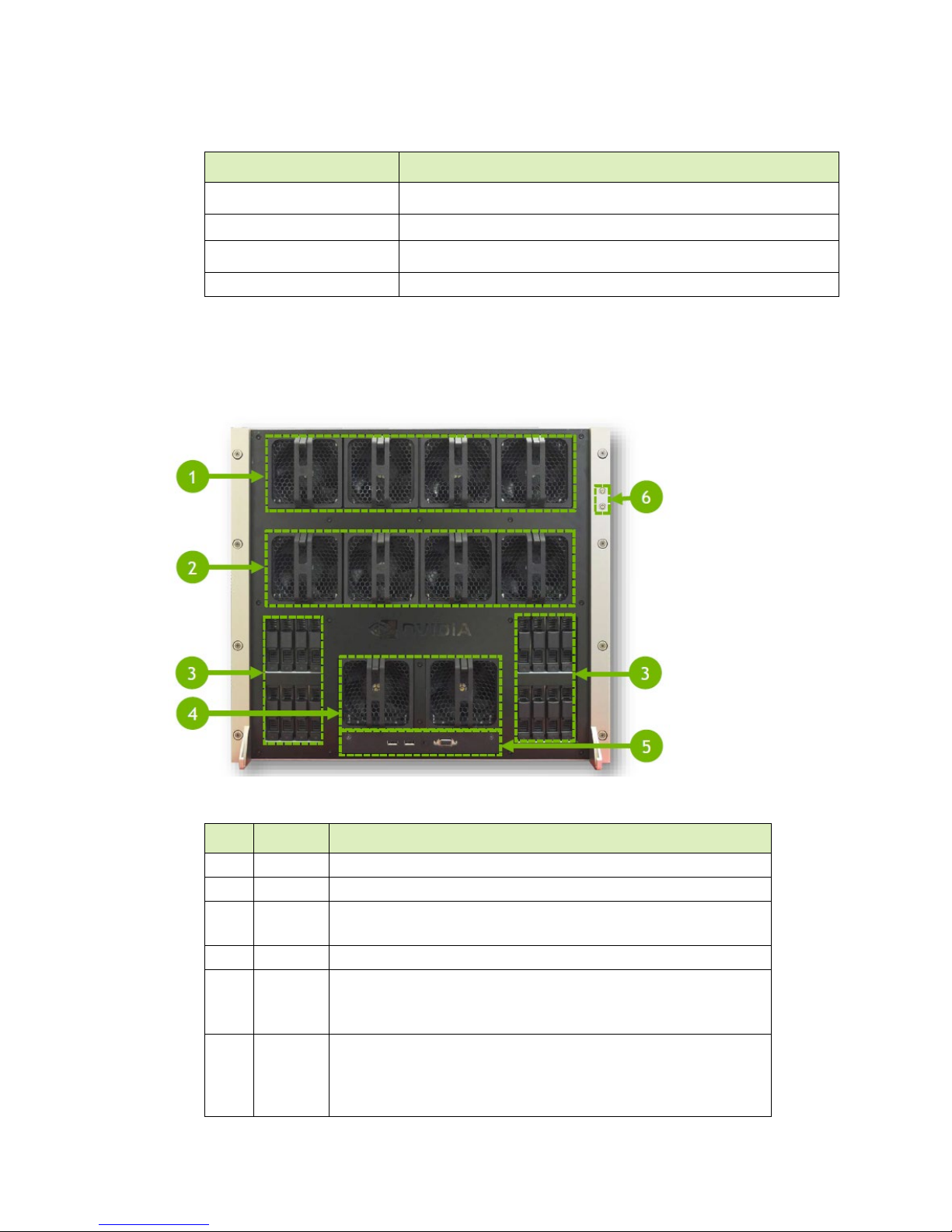
1.2.7 Rear Panel Connections and Controls
With EMI Shield Installed
ID Qty Description
1 1 EMI shield
2 6 Power supplies and connectors
3 1 I/O tray
4 1 Motherboard tray
5 2 Handles to pull power supply carrier
DGX-2 System User Guide
9
Page 10
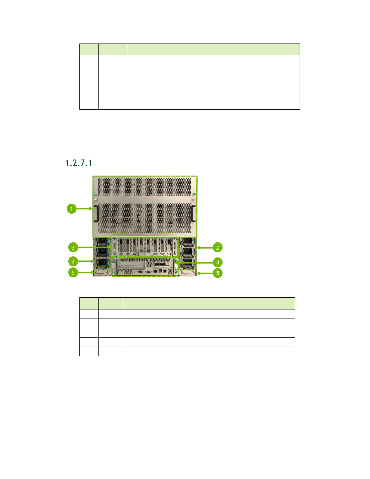
With EMI Shield Removed
ID
Qty
Description
ID
Qty
Description
enp134s0f1
1 2 NVIDIA NVLink™ plane card
Introduction to the NVIDIA DGX-2 System
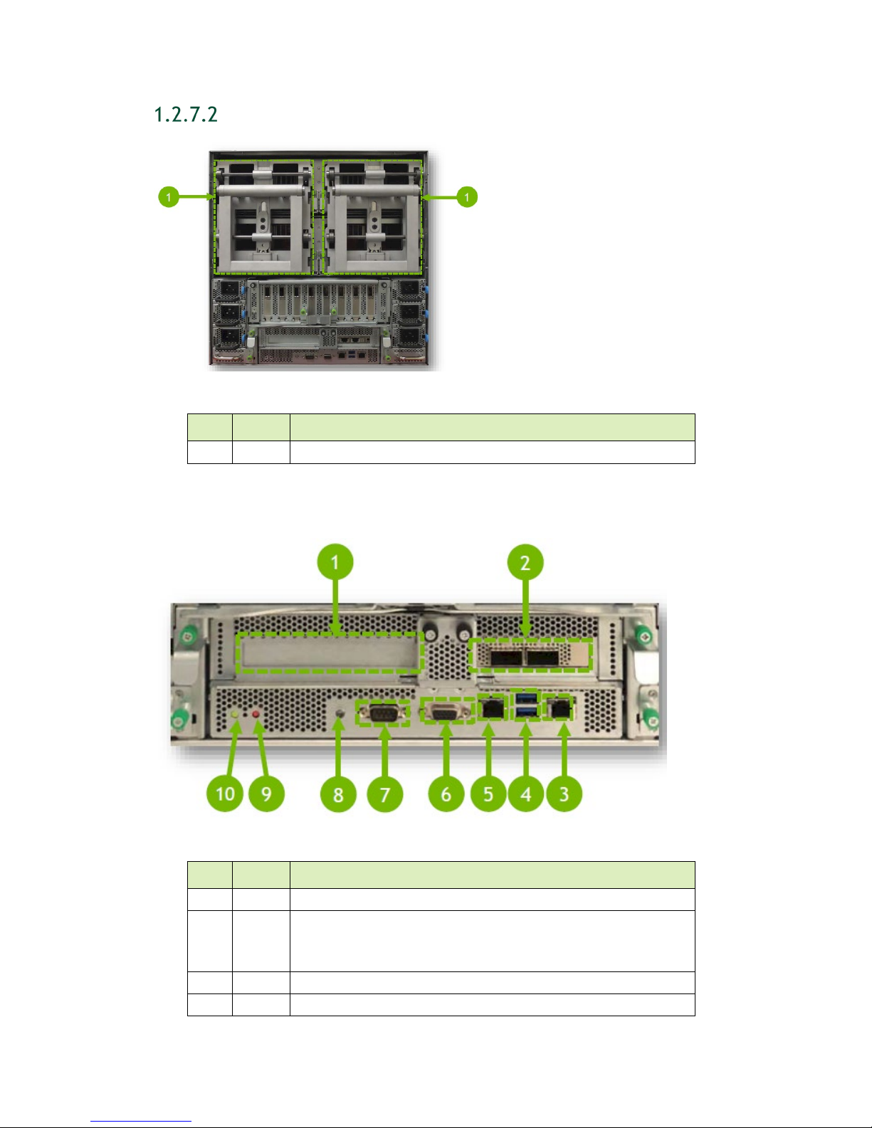
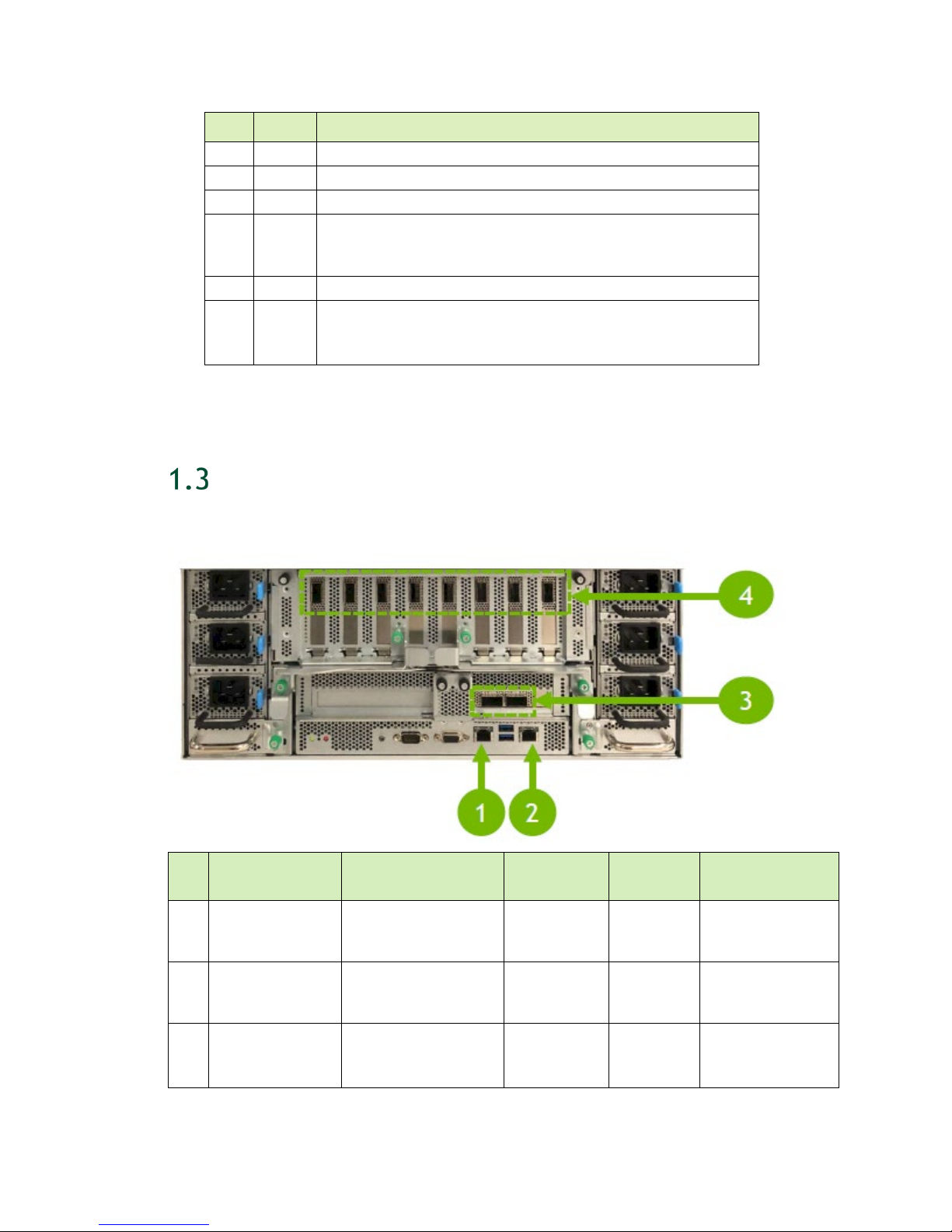
1.2.8 Motherboard Tray Ports and Controls
1 1 (Optional) High profile PCI card slot (for network storage)
2 2 (Default) QSFP28 network ports (for network storage)
Left side port designation: enp134s0f0
Right side port designation:
3 1 RJ45 network port (for in-band management)
4 2 USB 3.0 ports
DGX-2 System User Guide
10
Page 11
ID Qty Description
Ports
5 1 IPMI port (for out-of-band management (BMC))
6 1 VGA port
7 1 Serial port (DB-9)
8 1 System ID LED
Blinks blue when ID button is pressed from the front of the unit
as an aid in identifying the unit needing servicing
9 1 BMC reset button
10 1 Power and BMC heartbeat LED
On/Off – BMC is not ready
Blinking – BMC is ready
NETWORK PORTS
Introduction to the NVIDIA DGX-2 System
The following figure highlights the available network ports and their purpose.
ID Connectivity Uses
BMC (remote
1
management and
monitoring)
Motherboard
2
RJ45
3 ConnectX-5 (LP)
Ethernet mode
Out-of-band
management
In-band
management,
administration
Storage (NFS)
System
communication
Number of
1
1
2
(Left):
enp134s0f0
Port Type Cable Type
100/1000
RJ45
RJ45
QSFP28
Ethernet
Cat5E/6 Ethernet
100/1000
Ethernet
Cat5E/6 Ethernet
100 GbE (QSFP28)
10/25/40 GbE
DGX-2 System User Guide
11
Page 12
Introduction to the NVIDIA DGX-2 System
Ports
(Right):
enp134s0f1
(QSFP28 to SFP28
Ports
Type
enp134s0f1
ID Connectivity Uses
4 ConnectX-5
InfiniBand mode
Ethernet mode
Clustering
Storage
Number of
8
Port Type Cable Type
QSFP28
or SFP+)
InfiniBand EDR
100
Ethernet 100GbE
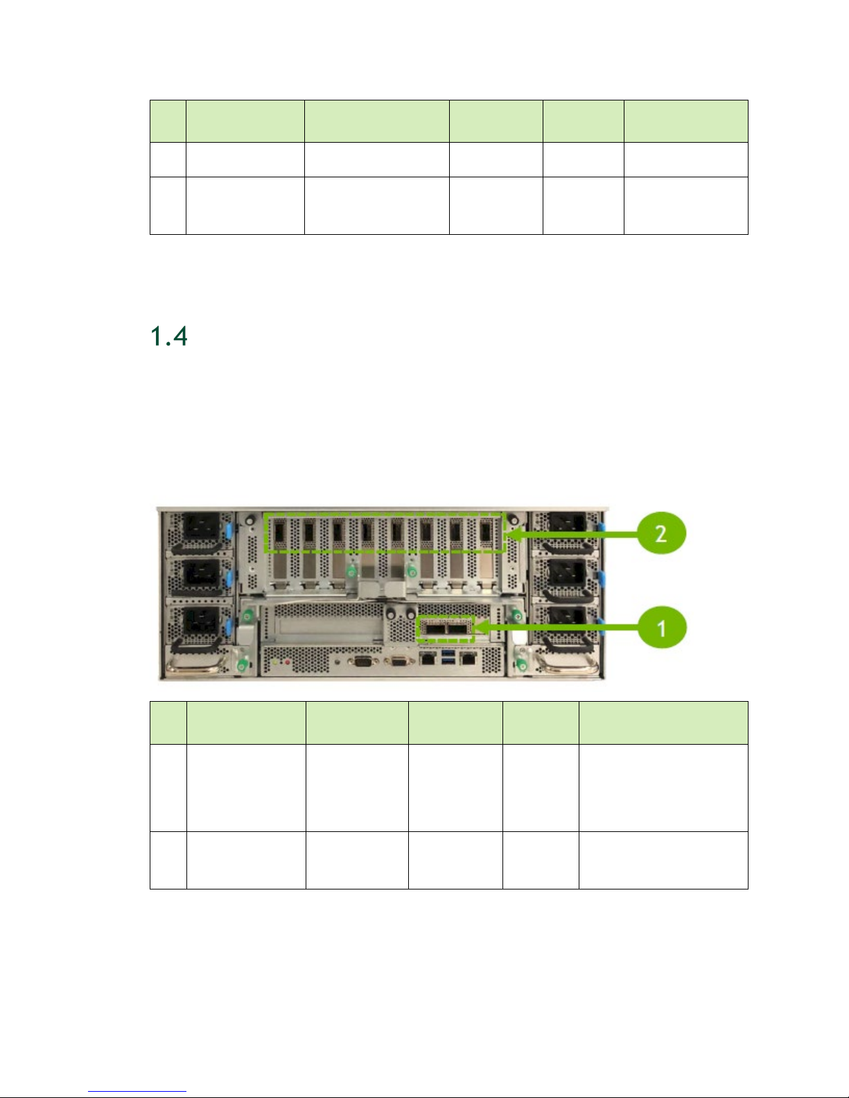
RECOMMENDED PORTS TO USE FOR EXTERNAL
STORAGE
For clarity, the following figure reiterates the recommended ports to use for external
storage. In most configurations, the storage ports (ID 1 below) should be used for
connecting to high-speed NAS storage, while the cluster ports (ID 2 below) should be
used for communication between nodes.
ID Connectivity Uses Number of
1 ConnectX-5 (LP) Storage (NFS) 2
2 ConnectX-5
InfiniBand mode
Ethernet mode
DGX-2 System User Guide
Port
(Left):
enp134s0f0
(Right):
Cluster
12
8
QSFP28 1/10/25/40/100 GbE
QSFP28
Cable Type
EDR InfiniBand or 100
GbE
Page 13
Introduction to the NVIDIA DGX-2 System
DGX OS SOFTWARE
The DGX-2 System comes installed with a base OS incorporating
An Ubuntu server distribution with supporting packages
The NVIDIA driver
Docker CE
NVIDIA Container Runtime for Docker
The following health monitoring software
● NVIDIA System Management (NVSM)
Provides active health monitoring and system alerts for NVIDIA DGX nodes in a
data center. It also provides simple commands for checking the health of the
DGX-2 SYSTEM from the command line.
● Data Center GPU Management (DCGM)
This software enables node-wide administration of GPUs, and can be used for
cluster and data-center level management.
ADDITIONAL DOCUMENTATION
Note: Some of the documentation listed below are not available at the time of
publication. See https://docs.nvidia.com/dgx/ for the latest status.
DGX-2 System Service Manual
Instructions for servicing the DGX-2 System, including how to replace select
components.
DGX OS Server Release Notes
Provides software component versions as well as a list of changes and known issues
in the installed OS software.
NGC Container Registry for DGX
How to access the NGC container registry for using containerized deep learning
GPU-accelerated applications on your DGX-2 System.
NVSM Software User Guide
Contains instructions for using the NVIDIA System Management software.
DCGM Software User Guide
Contains instructions for using the Data Center GPU Management software.
DGX-2 System User Guide
13
Page 14

Introduction to the NVIDIA DGX-2 System
CUSTOMER SUPPORT
Contact NVIDIA Enterprise Support for assistance in reporting, troubleshooting, or
diagnosing problems with your
Support for assistance in installing or moving the DGX-2 System. You can contact
NVIDIA Enterprise Support in the following ways.
1.7.1 NVIDIA Enterprise Support Portal
The best way to file an incident is to log on to the NVIDIA Enterprise Support portal.
1.7.2 NVIDIA Enterprise Support Email
You can also send an email to enterprisesupport@nvidia.com.
DGX-2 System. Also contact NVIDIA Enterprise
1.7.3 NVIDIA Enterprise Support - Local Time Zone
Phone Numbers
Visit the NVIDIA Enterprise Support page.
DGX-2 System User Guide
14
Page 15

CONNECTING TO THE DGX-2 CONSOLE
Connect to the DGX-2 console using either a direct connection, a remote connection
through the BMC, or through an SSH connection.
CAUTION: Connect directly to the DGX-2 console if the DGX-2 System is connected
to a 172.17.xx.xx subnet.
DGX OS Server software installs Docker CE which uses the 172.17.xx.xx subnet by
default for Docker containers. If the DGX-2 System is on the same subnet, you will not
be able to establish a network connection to the DGX-2 System.
Refer to the section Configuring Docker IP Addresses for instructions on how to change
the default Docker network settings.
DGX-2 System User Guide
15
Page 16
Connecting to the DGX-2 Console
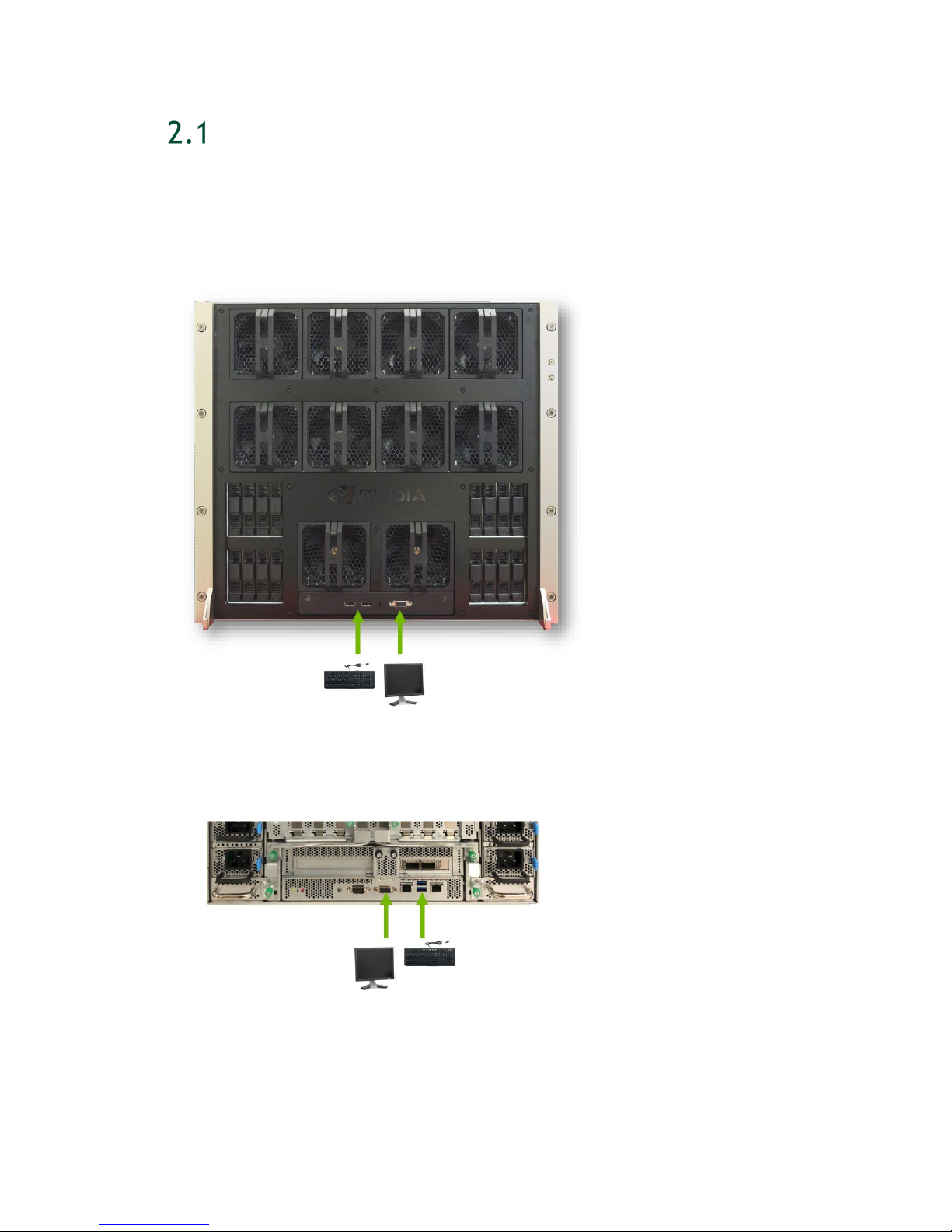
DIRECT CONNECTION
At either the front or the back of the DGX-2 System, connect a display to the VGA
connector, and a keyboard to any of the USB ports.
DGX-2 Server Front
DGX-2 Server Back
DGX-2 System User Guide
16
Page 17
Connecting to the DGX-2 Console
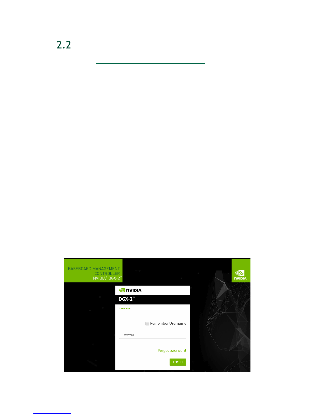
REMOTE CONNECTION THROUGH THE BMC
See the section Configuring Static IP Address for the BMC if you need to configure a
static IP address for the BMC.
This method requires that you have the BMC login credentials. These credentials
depend on the following conditions:
Prior to first time boot: The default credentials are
Username: admin
Password: admin
After first boot setup: The administrative user username that was set up during the
initial boot is used for both the BMC username and BMC password.
Username: <administrator-username>
Password: <administrator-username>
After first boot setup with changed password: The BMC password can be changed
from “<system-username>”, in which case the credentials are
Username: <administrator-username>
Password: <new-bmc-password>
1. Make sure you have connected the BMC port on the DGX-2 System to your LAN.
2. Open a browser within your LAN and go to:
https://<ipmi-ip-address>/
Make sure popups are allowed for the BMC address.
3. Log in.
DGX-2 System User Guide
17
Page 18
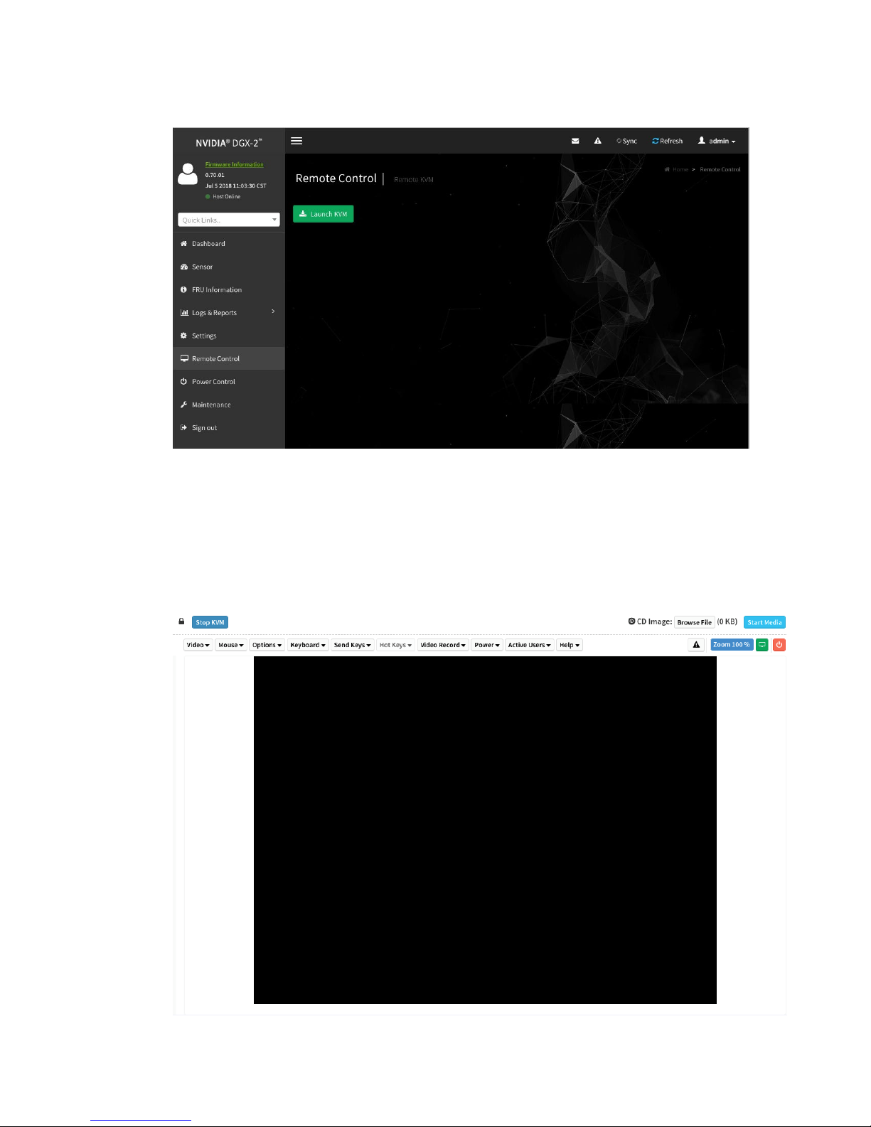
4. From the left-side navigation menu, click Remote Control.
Connecting to the DGX-2 Console
The Remote Control page allows you to open a virtual Keyboard/Video/Mouse
(KVM) on the DGX-2 System, as if you were using a physical monitor and keyboard
connected to the front of the system.
5. Click Launch KVM.
The DGX-2 console appears in your browser.
DGX-2 System User Guide
18
Page 19

Connecting to the DGX-2 Console
SSH CONNECTION
You can also establish an SSH connection to the DGX-2 System through the network
port. See the section Network Ports
Configuring Static IP Addresses for the Network Ports if you need to configure a static
IP address.
to identify the port to use, and the section
DGX-2 System User Guide
19
Page 20

SETTING UP THE DGX-2 SYSTEM
While NVIDIA service personnel will install the DGX-2 System at the site and perform
the first boot setup, the first boot setup instructions are provided here for reference and
to support any re-imaging of the server.
These instructions describe the setup process that occurs the first time the DGX-2 System
is powered on after delivery or after the server is re-imaged.
Be prepared to accept all End User License Agreements (EULAs) and to set up your
username and password.
1. Connect to the DGX-2 console as explained in Connecting to the DGX-2 Console.
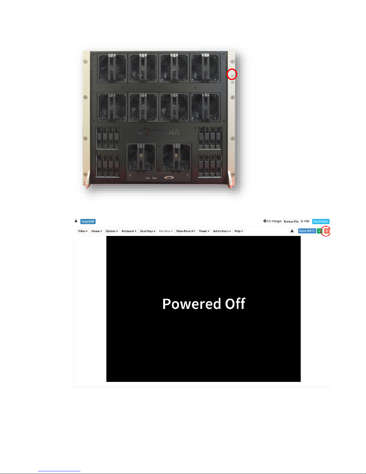
2. Power on the DGX-2 System.
● Using the physical power button
DGX-2 System User Guide
20
Page 21
Setting Up the DGX-2 System
● Using the Remote BMC
The system will take a few minutes to boot.
You are presented with end user license agreements (EULAs) for the NVIDIA
software.
DGX-2 System User Guide
21
Page 22

Setting Up the DGX-2 System
!
3. Accept all EULAs to proceed with the installation.
The system boots and you are prompted to configure the DGX-2 software.
4. Perform the steps to configure the DGX-2 software.
● Select your language and location.
● Create a user account with your name, username, and password.
You will need these credentials to log in to the DGX-2 System as well as to log in to
the BMC remotely. When logging in to the BMC, enter your username for both the
User ID as well as the password. Be sure to create a unique BMC password at the
first opportunity.
CAUTION: Once you create your login credentials, the default admin/admin login will
no longer work.
Note: The BMC software will not accept "sysadmin" for a user name. If you create this
user name for the system log in, "sysadmin" will not be available for logging in to the
BMC.
● Choose a primary network interface for the DGX-2 System; for example, enp6s0.
This should typically be the interface that you will use for subsequent system
configuration or in-band management.
Note: After you select the primary network interface, the system attempts to configure
the interface for DHCP and then asks you to enter a hostname for the system. If DHCP
is not available, you will have the option to configure the network manually. If you
need to configure a static IP address on a network interface connected to a DHCP
network, select Cancel at the Network configuration – Please enter the
hostname for the system screen. The system will then present a screen with the
option to configure the network manually.
● Choose a host name for the DGX-2 System.
After completing the setup process, the DGX-2 System reboots automatically and
then presents the login prompt.
5. Update the software to ensure you are running the latest version.
Updating the software ensures your DGX-2 System contains important updates,
including security updates. The Ubuntu Security Notice site (https://usn.ubuntu.com/
lists known Common Vulnerabilities and Exposures (CVEs), including those that can be
resolved by updating the DGX OS software.
)
a) Run the package manager.
DGX-2 System User Guide
22
Page 23

$ sudo apt update
b) Upgrade to the latest version.
$ sudo apt full-upgrade
Note: RAID 1 Rebuild in Progress - When the system is booted after restoring the
image, software RAID begins the process of rebuilding the RAID 1 array - creating a
mirror of (or resynchronizing) the drive containing the software. System performance
may be affected during the RAID 1 rebuild process, which can take an hour to
complete.
During this time, the command “nvsm show health” will report a warning that the RAID
volume is resyncing.
You can check the status of the RAID 1 rebuild process using “sudo mdadm -D
/dev/md0”.
Setting Up the DGX-2 System
DGX-2 System User Guide
23
Page 24

QUICK START INSTRUCTIONS
This chapter provides basic requirements and instructions for using the DGX-2 System,
including how to perform a preliminary health check and how to prepare for running
containers. Be sure to visit the DGX documentation website at
https://docs.nvidia.com/dgx/
for additional product documentation.
REGISTRATION
Be sure to register your DGX-2 System with NVIDIA as soon as you receive your
purchase confirmation e-mail. Registration enables your hardware warranty and allows
you to set up an NVIDIA GPU Cloud for DGX account.
To register your DGX-2 System, you will need information provided in your purchase
confirmation e-mail. If you do not have the information, send an e-mail to NVIDIA
Enterprise Support at enterprisesupport@nvidia.com.
1. From a browser, go to the NVIDIA DGX Product Registration page
(https://www.nvidia.com/object/dgx-product-registration
2. Enter all required information and then click SUBMIT to complete the registration
process and receive all warranty entitlements and DGX-2 support services
entitlements.
).
DGX-2 System User Guide
24
Page 25

Quick Start Instructions
INSTALLATION AND CONFIGURATION
Your DGX-2 System will be installed by NVIDIA service personnel or an authorized
installation partner.
Before installation, make sure you have completed the Site Survey and have given all
relevant site information to your Installation Partner.
OBTAINING AN NVIDIA GPU CLOUD ACCOUNT
NVIDIA GPU Cloud (NGC) provides simple access to GPU-optimized software tools for
deep learning and high-performance computing (HPC) that take full advantage of
NVIDIA GPUs. An NGC account grants you access to these tools as well as the ability to
set up a private registry to manage your customized tools.
Work with NVIDIA Enterprise Support to set up an NGC enterprise account if you are
the organization administrator for your DGX-2 purchase. See the NGC Container
Registry for DGX User Guide (
guide/) for detailed instructions on getting an NGC enterprise account.
https://docs.nvidia.com/dgx/ngc-registry-for-dgx-user-
GETTING YOUR NGC API KEY AND SELECTING
CONTAINER TAGS FOR THE VERIFICATION
EXAMPLES
Before using the DGX-2 System to run containers from the NGC container registry, you
must visit the NGC web site to obtain your NGC API Key and to determine which
containers are available to run.
4.4.1 Getting Your NGC API Key
Your NGC API Key authenticates your access to the NGC container registry with its
NVIDIA tuned, tested, certified, and maintained containers for the top deep learning
frameworks.
You only need to generate an API Key once. Should you lose your API Key, you can
generate a new one from the NGC website. When you generate a new API Key, the old
one is invalidated.
Perform the following instructions from any system with internet access and a browser.
DGX-2 System User Guide
25
Page 26

Quick Start Instructions
1. Log in to the NGC website (https://ngc.nvidia.com).
2. Click Get API Key from the Registry page.
3. Click Generate API Key from the Configuration->API Key page.
4. Click Confirm at the Generate a New API Key dialog.
Your NGC API Key is displayed at the bottom of the Configuration->API Key page
with examples of how to use it.
NGC does not save your key, so store it in a secure place. You can copy your API Key
to the clipboard by clicking the copy icon to the right of the API key.
4.4.2 Selecting CUDA Container Tags for Verification
Examples
While you are logged in to the web site, select a CUDA container tag to use for the
verification procedure in the next section.
1. Select Registry from the left side menu.
2. Select a CUDA container tag.
c) Click the cuda repository (under the nvidia registry space).
d) In the Tag section, scroll down to find the latest ‘-runtime’ version. For example,
‘10.0-runtime’.
Note this tag as you will need to specify it when running the CUDA container in the
next section.
VERIFYING BASIC FUNCTIONALITY
This section walks you through the steps of performing a health check on the DGX-2
System, and verifying the Docker and NVIDIA driver installation.
1. Establish an SSH connection to the DGX-2 System.
2. Run a basic system check.
sudo nvsm show health
Verify that the output summary shows that all checks are Healthy and that the overall
system status is Healthy.
3. Verify that Docker is installed by viewing the installed Docker version.
sudo docker --version
This should return the version as “Docker version 18.03-ce”, where the actual
version may differ depending on the specific release of the DGX OS Server software.
DGX-2 System User Guide
26
Page 27

Quick Start Instructions
4. Verify connection to the NVIDIA repository and that the NVIDIA Driver is installed.
sudo docker container run --runtime=nvidia --rm
nvcr.io/nvidia/cuda:<cuda-tag-obtained-from-previous-
section> nvidia-smi
Docker pulls the nvidia/cuda container image layer by layer, then runs nvidia-smi.
When completed, the output should show the NVIDIA Driver version and a
description of each installed GPU.
See the NVIDIA Containers and Deep Learning Frameworks User Guide at
https://docs.nvidia.com/deeplearning/dgx/user-guide/index.html
for further
instructions, including an example of logging into the NGC container registry and
launching a deep learning container.
DGX-2 System User Guide
27
Page 28
NETWORK CONFIGURATION
This chapter describes key network considerations and instructions for the DGX-2
System.
BMC SECURITY
NVIDIA recommends that customers follow best security practices for BMC
management (IPMI port). These include, but are not limited to, such measures as:
Restricting the DGX-2 IPMI port to an isolated, dedicated, management network
Using a separate, firewalled subnet
Configuring a separate VLAN for BMC traffic if a dedicated network is not available
CONFIGURING NETWORK PROXIES
If your network requires use of a proxy server, you will need to set up configuration
files to ensure the DGX-2 System communicates through the proxy.
5.2.1 For the OS and Most Applications
Edit the file /etc/environment and add the following proxy addresses to the file,
below the PATH line.
http_proxy="http://<username>:<password>@<host>:<port>/"
ftp_proxy="ftp://<username>:<password>@<host>:<port>/";
DGX-2 System User Guide
28
Page 29
Network Configuration
https_proxy="https://<username>:<password>@<host>:<port>/";
no_proxy="localhost,127.0.0.1,localaddress,.localdomain.com"
HTTP_PROXY="http://<username>:<password>@<host>:<port>/"
FTP_PROXY="ftp://<username>:<password>@<host>:<port>/";
HTTPS_PROXY="https://<username>:<password>@<host>:<port>/";
NO_PROXY="localhost,127.0.0.1,localaddress,.localdomain.com"
Where username and password are optional.
Example:
http_proxy="http://myproxy.server.com:8080/"
ftp_proxy="ftp://myproxy.server.com:8080/";
https_proxy="https://myproxy.server.com:8080/";
5.2.2 For apt
Edit (or create) a proxy config file /etc/apt/apt.conf.d/myproxy and include the
following lines
Acquire::http::proxy "http://<username>:<password>@<host>:<port>/";
Acquire::ftp::proxy "ftp://<username>:<password>@<host>:<port>/";
Acquire::https::proxy "https://<username>:<password>@<host>:<port>/";
Where username and password are optional.
Example:
Acquire::http::proxy "http://myproxy.server.com:8080/";
Acquire::ftp::proxy "ftp://myproxy.server.com:8080>/";
Acquire::https::proxy "https://myproxy.server.com:8080/";
5.2.3 For Docker
To ensure that Docker can access the NGC container registry through a proxy, Docker
uses environment variables. For best practice recommendations on configuring proxy
environment variables for Docker,
see https://docs.docker.com/engine/admin/systemd/#http-proxy.
CONFIGURING DOCKER IP ADDRESSES
To ensure that the DGX-2 System can access the network interfaces for Docker
containers, Docker should be configured to use a subnet distinct from other network
resources used by the DGX-2 System.
DGX-2 System User Guide
29
Page 30

Network Configuration
By default, Docker uses the 172.17.0.0/16 subnet. Consult your network administrator
to find out which IP addresses are used by your network.
If your network does not
conflict with the default Docker IP address range, then no changes are needed and
you can skip this section.
However, if your network uses the addresses within this range for the DGX-2 System,
you should change the default Docker network addresses.
You can change the default Docker network addresses by either modifying
/etc/docker/daemon.json file or modifying the /etc/systemd/
the
system/docker.service.d/docker-override.conf
file. These instructions provide
an example of modifying the/etc/systemd/system/docker.service.d/docker-
override.conf to override the default Docker network addresses.
1. Open the docker-override.conf file for editing.
$ sudo vi /etc/systemd/system/docker.service.d/docker-override.conf
[Service]
ExecStart=
ExecStart=/usr/bin/dockerd -H fd:// -s overlay2
LimitMEMLOCK=infinity
LimitSTACK=67108864
2. Make the changes indicated in bold below, setting the correct bridge IP address and
IP address ranges for your network. Consult your IT administrator for the correct
addresses.
[Service]
ExecStart=
ExecStart=/usr/bin/dockerd -H fd:// -s overlay2 --bip=192.168.127.1/24
--fixed-cidr=192.168.127.128/25
LimitMEMLOCK=infinity
LimitSTACK=67108864
Save and close the /etc/systemd/system/docker.service.d/dockeroverride.conf file when done.
3. Reload the systemctl daemon.
$ sudo systemctl daemon-reload
4. Restart Docker.
$ sudo systemctl restart docker
DGX-2 System User Guide
30
Page 31

Network Configuration
Port (Protocol)
Direction
Use
OPENING PORTS
Make sure that the ports listed in the following table are open and available on
your firewall to the DGX-2 System:
22 (TCP) Inbound SSH
53 (UDP) Outbound DNS
80 (TCP) Outbound HTTP, package updates
443 (TCP) Outbound
443 (TCP) Inbound
For internet (HTTP/HTTPS) connection to
NVIDIA GPU Cloud
If port 443 is proxied through a corporate
firewall, then WebSocket protocol traffic
must be supported
For BMC web services, remote console
services, and cd-media service.
If port 443 is proxied through a corporate
firewall, then WebSocket protocol traffic
must be supported
CONNECTIVITY REQUIREMENTS
To run NVIDIA NGC containers from the NGC container registry, your network must
be able to access the following URLs:
http://archive.ubuntu.com/ubuntu/
http://security.ubuntu.com/ubuntu/
http://international.download.nvidia.com/dgx/repos/
https://apt.dockerproject.org/repo/
https://download.docker.com/linux/ubuntu/
https://nvcr.io/
To verify connection to nvcr.io, run
$ wget https://nvcr.io/v2
You should see connecting verification followed by a 401 error.
--2018-08-01 19:42:58-- https://nvcr.io/v2
Resolving nvcr.io (nvcr.io)... 52.8.131.152, 52.9.8.8
Connecting to nvcr.io (nvcr.io)|52.8.131.152|:443... connected.
HTTP request sent, awaiting response... 401 Unauthorized
DGX-2 System User Guide
31
Page 32
Network Configuration
CONFIGURING STATIC IP ADDRESS FOR THE
BMC
This section explains how to set a static IP address for the BMC. You will need to do this
if your network does not support DHCP.
Use one of the methods described in the following sections:
Configuring a BMC Static IP Address Using ipmitool
Configuring a BMC Static IP Address Using the System BIOS
Configuring a BMC Static IP Address Using the BMC Dashboard
5.6.1 Configuring a BMC Static IP Address Using
ipmitool
This section describes how to set a static IP address for the BMC from the Ubuntu
command line.
Note: If you cannot access the DGX-2 System remotely, then connect a display
(1440x900 or lower resolution) and keyboard directly to the DGX-2 System.
To view the current settings, enter the following command.
$ sudo ipmitool lan print 1
To set a static IP address for the BMC, do the following.
1. Set the IP address source to static.
$ sudo ipmitool lan set 1 ipsrc static
2. Set the appropriate address information.
● To set the IP address (“Station IP address” in the BIOS settings), enter the
following and replace the italicized text with your information.
$ sudo ipmitool lan set 1 ipaddr 10.31.241.190
● To set the subnet mask, enter the following and replace the italicized text with
your information.
$ sudo ipmitool lan set 1 netmask 255.255.255.0
DGX-2 System User Guide
32
Page 33
Network Configuration
● To set the default gateway IP (“Router IP address” in the BIOS settings), enter the
following and replace the italicized text with your information.
$ sudo ipmitool lan set 1 defgw ipaddr 10.31.241.1
5.6.2 Configuring a BMC Static IP Address Using the
System BIOS
This section describes how to set a static IP address for the BMC when you cannot access
the DGX-2 System remotely. This process involves setting the BMC IP address during
system boot.
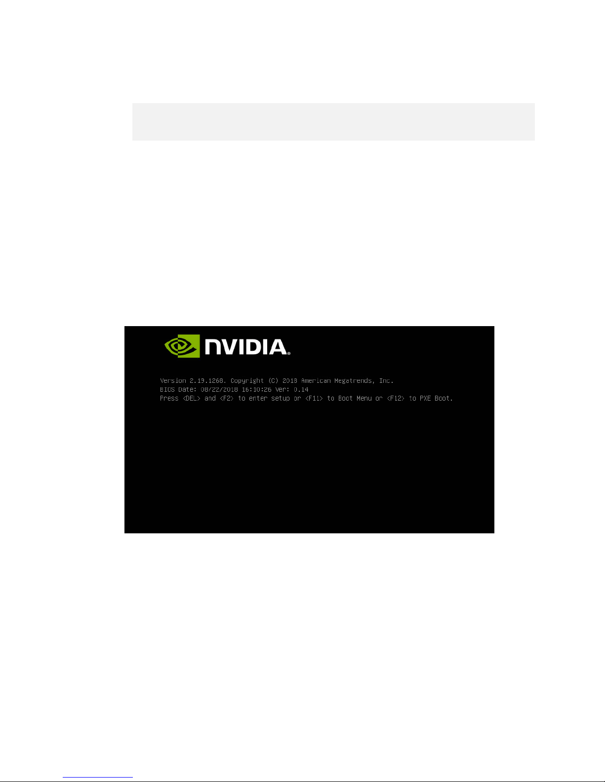
1. Connect a keyboard and display (1440 x 900 maximum resolution) to the DGX-2
System, then turn on the DGX-2 System.
2. When you see the SBIOS version screen, press Del or F2 to enter the BIOS Setup
Utility screen.
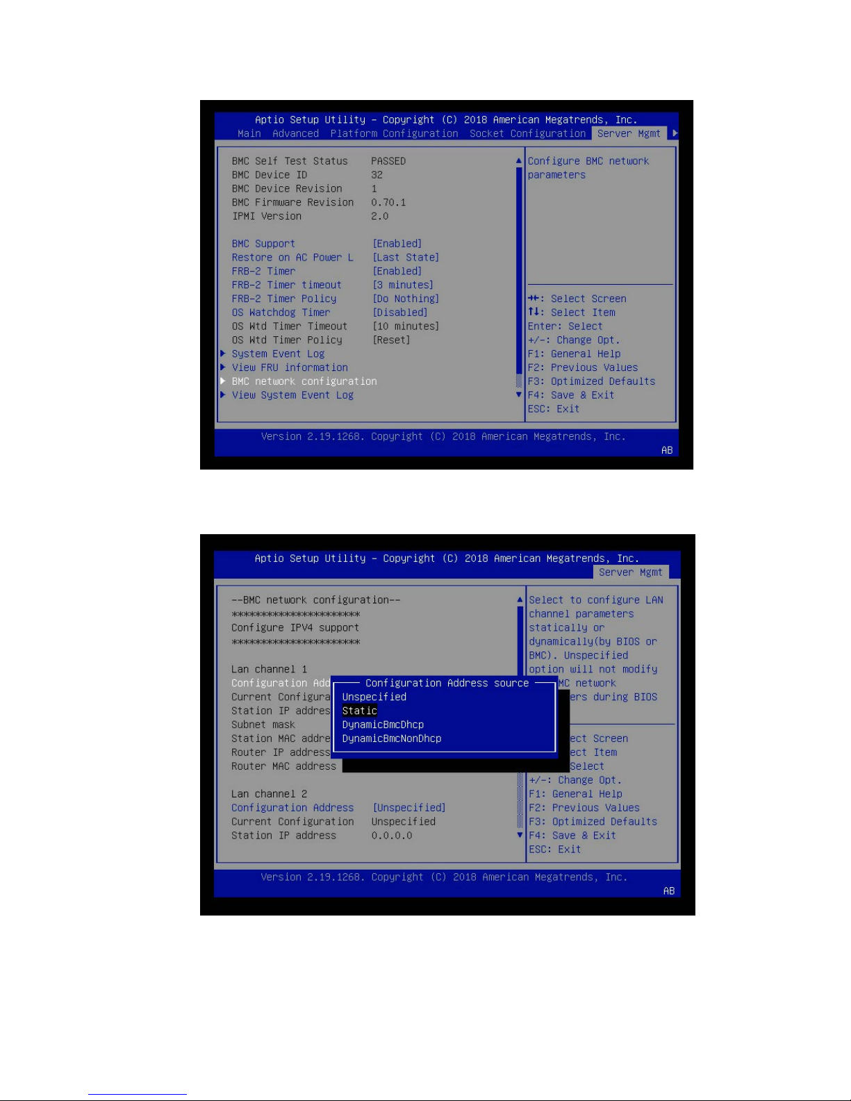
3. At the BIOS Setup Utility screen, navigate to the Server Mgmt tab on the top menu,
then scroll to BMC network configuration and press Enter.
DGX-2 System User Guide
33
Page 34
Network Configuration
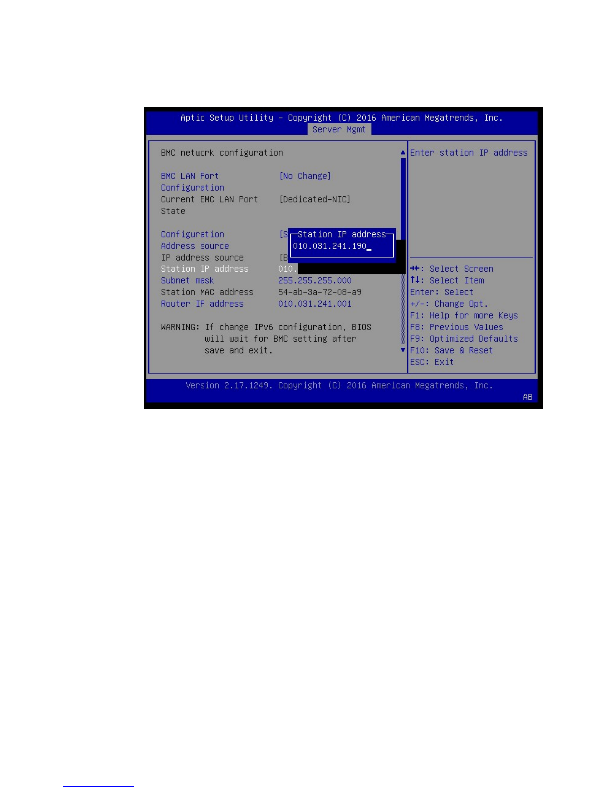
4. Scroll to Configuration Address Source and press Enter, then at the Configuration
Address source pop-up, select Static and then press Enter.
5. Set the addresses for the Station IP address, Subnet mask, and Router IP address as
needed by performing the following for each:
DGX-2 System User Guide
34
Page 35
Network Configuration
a) Scroll to the specific item and press Enter.
b) Enter the appropriate information at the pop-up, then press Enter.
6. When finished making all your changes, press F10 to save & exit
You can now access the BMC over the network.
5.6.3 Configuring a BMC Static IP Address Using the
BMC Dashboard
These instructions describe IPv4 addressing, but IPv6 addressing to the BMC can be
configured if needed through the corresponding IPv6 fields.
1. Log into the BMC, then click Settings->Network Settings->Network IP Settings.
2. Clear the Enable IPv4 DHCP check box, then enter the appropriate values for
the IPv4 Address, IPv4 Subnet, and IPv4 Gateway fields
.
DGX-2 System User Guide
35
Page 36

Network Configuration
3. Click Save when done.
CONFIGURING STATIC IP ADDRESSES FOR THE
NETWORK PORTS
During the initial boot setup process for the DGX-2 System, you had an opportunity to
configure static IP addresses for a single network interface. If you did not set this up at
that time, you can configure the static IP addresses from the Ubuntu command line
using the following instructions.
Note: If you cannot access the DGX-2 System remotely, then connect a display
(1440x900 or lower resolution) and keyboard directly to the DGX-2 System.
1. Determine the port designation that you want to configure, based on the physical
ethernet port that you have connected to your network.
DGX-2 System User Guide
36
Page 37

Ethernet Port Position
<port-designation>
enp134s0f0
enp134s0f1
enp6s0
Network Configuration
1
2
3
2. Edit the network configuration yaml file.
$ sudo vi /etc/netplan/01-netcfg.yaml
network:
version: 2
renderer: networkd
ethernets:
<port-designation>:
dhcp4: no
dhcp6: no
addresses: 10.10.10.2/24
gateway4: 10.10.10.1
nameservers:
search: [<mydomain>, <other-domain>]
addresses: [10.10.10.1, 1.1.1.1]
Consult your network administrator for the appropriate information for the items in
bold, such as network, gateway, and nameserver addresses, and use the port
designations that you determined in step 1.
3. When finished with your edits, press ESC to switch to command mode, then save
the file to the disk and exit the editor.
4. Apply the changes.
$ sudo netplan apply
DGX-2 System User Guide
37
Page 38

Network Configuration
Note: If you are not returned to the command line prompt after a minute, then reboot
the system.
For additional information, see
https://help.ubuntu.com/lts/serverguide/network-
configuration.html.en.
SWITCHING BETWEEN INFINIBAND AND
ETHERNET
The NVIDIA DGX-2 System is equipped with eight QSFP28 network ports on the I/O
board, typically used for cluster communications. By default these are configured as
InfiniBand ports, but you have the option to convert these to Ethernet ports.
For these changes to work properly, the configured port must connect to a networking
switch that matches the port configuration. In other words, if the port configuration is
set to InfiniBand, then the external switch should be an InfiniBand switch with the
corresponding InfiniBand cables. Likewise, if the port configuration is set to Ethernet,
then the switch should also be Ethernet.
5.8.1 Starting the Mellanox Software Tools
1. Start the mst driver.
$ sudo mst start
2. To verify that the Mellanox Software Tools (MST) services are running, enter the
following.
$ sudo mst status
● The following output indicates the services are not running.
MST modules:
------------
MST PCI module is not loaded
MST PCI configuration module is not loaded
● The following output indicates the services are running.
MST modules:
------------
DGX-2 System User Guide
38
Page 39

Network Configuration
MST PCI module is not loaded
MST PCI configuration module loaded
MST devices:
------------
/dev/mst/mt4119_pciconf0 - PCI configuration cycles access.
domain:bus:dev.fn=0000:35:00.0 addr.reg=88 data.reg=92
Chip revision is: 00
/dev/mst/mt4119_pciconf1 - PCI configuration cycles access.
domain:bus:dev.fn=0000:3a:00.0 addr.reg=88 data.reg=92
Chip revision is: 00
/dev/mst/mt4119_pciconf2 - PCI configuration cycles access.
domain:bus:dev.fn=0000:58:00.0 addr.reg=88 data.reg=92
Chip revision is: 00
/dev/mst/mt4119_pciconf3 - PCI configuration cycles access.
domain:bus:dev.fn=0000:5d:00.0 addr.reg=88 data.reg=92
Chip revision is: 00
/dev/mst/mt4119_pciconf4 - PCI configuration cycles access.
domain:bus:dev.fn=0000:b8:00.0 addr.reg=88 data.reg=92
Chip revision is: 00
/dev/mst/mt4119_pciconf5 - PCI configuration cycles access.
domain:bus:dev.fn=0000:bd:00.0 addr.reg=88 data.reg=92
Chip revision is: 00
/dev/mst/mt4119_pciconf6 - PCI configuration cycles access.
domain:bus:dev.fn=0000:e1:00.0 addr.reg=88 data.reg=92
Chip revision is: 00
/dev/mst/mt4119_pciconf7 - PCI configuration cycles access.
domain:bus:dev.fn=0000:e6:00.0 addr.reg=88 data.reg=92
Chip revision is: 00
/dev/mst/mt4119_pciconf0 - PCI configuration cycles access.
domain:bus:dev.fn=0000:86:00.0 addr.reg=88 data.reg=92
Chip revision is: 00
$
DGX-2 System User Guide
39
Page 40

Network Configuration
5.8.2 Determining the Current Port Configuration
To determine the current port configuration, enter the following:
$ sudo mlxconfig query | egrep -e Device\|LINK_TYPE
Device #1:
Device type: ConnectX5
Device: 0000:bd:00.0
LINK_TYPE_P1 IB(1)
Device #2:
Device type: ConnectX5
Device: 0000:b8:00.0
LINK_TYPE_P1 IB(1)
Device #3:
Device type: ConnectX5
Device: 0000:3a:00.0
LINK_TYPE_P1 IB(1)
Device #4:
Device type: ConnectX5
Device: 0000:e1:00.0
LINK_TYPE_P1 IB(1)
Device #5:
Device type: ConnectX5
Device: 0000:35:00.0
LINK_TYPE_P1 IB(1)
Device #6:
Device type: ConnectX5
Device: 0000:5d:00.0
LINK_TYPE_P1 IB(1)
Device #7:
Device type: ConnectX5
Device: 0000:e6:00.0
LINK_TYPE_P1 IB(1)
Device #8:
Device type: ConnectX5
Device: 0000:58:00.0
LINK_TYPE_P1 IB(1)
Device #9:
Device type: ConnectX5
Device: 0000:86:00.0
LINK_TYPE_P1 ETH(2)
LINK_TYPE_P2 ETH(2)
This output shows the first eight cards are configured for InfiniBand and correspond to
the network cluster ports. The last card has two ports which correspond to the two
network storage ports. These are configured for Ethernet should not be changed.
Map the Device bus numbers from your output to the device name from the mst
status output on your system. For example, this example output shows that the
device name for bus bd is /dev/mst/mt4119_pciconf5. You will need the device
name when changing the configuration.
DGX-2 System User Guide
40
Page 41

Network Configuration
5.8.3 Switching the Port from InfiniBand to
Ethernet
Make sure that you have started the Mellanox Software Tools (MST) services as explain
in the section Starting the Mellanox Software Tools
, and have identified the correct ports
to change.
1. Change the configuration for the network cluster ports to Ethernet by setting
LINK_TYPE_P1=2 for each port.
The following example configures the 8 network cluster ports.
~$ sudo mlxconfig -y -d /dev/mst/mt4119_pciconf0 set LINK_TYPE_P1=2
~$ sudo mlxconfig -y -d /dev/mst/mt4119_pciconf1 set LINK_TYPE_P1=2
~$ sudo mlxconfig -y -d /dev/mst/mt4119_pciconf2 set LINK_TYPE_P1=2
~$ sudo mlxconfig -y -d /dev/mst/mt4119_pciconf3 set LINK_TYPE_P1=2
~$ sudo mlxconfig -y -d /dev/mst/mt4119_pciconf4 set LINK_TYPE_P1=2
~$ sudo mlxconfig -y -d /dev/mst/mt4119_pciconf5 set LINK_TYPE_P1=2
~$ sudo mlxconfig -y -d /dev/mst/mt4119_pciconf6 set LINK_TYPE_P1=2
~$ sudo mlxconfig -y -d /dev/mst/mt4119_pciconf7 set LINK_TYPE_P1=2
2. Reboot the server.
3. Verify the configuration changes have been applied.
$ sudo mlxconfig query | egrep -e Device\|LINK_TYPE
Device #1:
Device type: ConnectX4
Device: 0000:bd:00.0
LINK_TYPE_P1 ETH (1)
Device #2:
Device type: ConnectX4
Device: 0000:b8:00.0
LINK_TYPE_P1 ETH (1)
Device #3:
Device type: ConnectX4
Device: 0000:3a:00.0
LINK_TYPE_P1 ETH (1)
Device #4:
Device type: ConnectX4
Device: 0000:e1:00.0
LINK_TYPE_P1 ETH (1)
Device #5:
Device type: ConnectX4
Device: 0000:35:00.0
LINK_TYPE_P1 ETH (1)
Device #6:
Device type: ConnectX4
Device: 0000:5d:00.0
LINK_TYPE_P1 ETH (1)
Device #7:
Device type: ConnectX4
DGX-2 System User Guide
41
Page 42

Network Configuration
Device: 0000:e6:00.0
LINK_TYPE_P1 ETH (1)
Device #8:
Device type: ConnectX4
Device: 0000:58:00.0
LINK_TYPE_P1 ETH (1)
Device #9:
Device type: ConnectX5
Device: 0000:86:00.0
LINK_TYPE_P1 ETH(2)
LINK_TYPE_P2 ETH(2)
5.8.4 Switching the Port from Ethernet to
InfiniBand
Make sure that you have started the Mellanox Software Tools (MST) as explain in the
section Starting the Mellanox Software Tools
, and have identified the correct ports to
change.
1. Change the configuration for the network cluster ports to InfiniBand by setting
LINK_TYPE_P1=1 for each port.
The following example configures all 8 network cluster ports.
~$ sudo mlxconfig -y -d /dev/mst/mt4119_pciconf0 set LINK_TYPE_P1=1
~$ sudo mlxconfig -y -d /dev/mst/mt4119_pciconf1 set LINK_TYPE_P1=1
~$ sudo mlxconfig -y -d /dev/mst/mt4119_pciconf2 set LINK_TYPE_P1=1
~$ sudo mlxconfig -y -d /dev/mst/mt4119_pciconf3 set LINK_TYPE_P1=1
~$ sudo mlxconfig -y -d /dev/mst/mt4119_pciconf4 set LINK_TYPE_P1=1
~$ sudo mlxconfig -y -d /dev/mst/mt4119_pciconf5 set LINK_TYPE_P1=1
~$ sudo mlxconfig -y -d /dev/mst/mt4119_pciconf6 set LINK_TYPE_P1=1
~$ sudo mlxconfig -y -d /dev/mst/mt4119_pciconf7 set LINK_TYPE_P1=1
2. Verify the configuration changes have been applied.
$ sudo mlxconfig query | egrep -e Device\|LINK_TYPE
Device #1:
Device type: ConnectX4
Device: 0000:bd:00.0
LINK_TYPE_P1 IB(1)
Device #2:
Device type: ConnectX4
Device: 0000:b8:00.0
LINK_TYPE_P1 IB(1)
Device #3:
Device type: ConnectX4
Device: 0000:3a:00.0
LINK_TYPE_P1 IB(1)
Device #4:
Device type: ConnectX4
Device: 0000:e1:00.0
LINK_TYPE_P1 IB(1)
DGX-2 System User Guide
42
Page 43

Device #5:
Device type: ConnectX4
Device: 0000:35:00.0
LINK_TYPE_P1 IB(1)
Device #6:
Device type: ConnectX4
Device: 0000:5d:00.0
LINK_TYPE_P1 IB(1)
Device #7:
Device type: ConnectX4
Device: 0000:e6:00.0
LINK_TYPE_P1 IB(1)
Device #8:
Device type: ConnectX4
Device: 0000:58:00.0
LINK_TYPE_P1 IB(1)
Device #9:
Device type: ConnectX5
Device: 0000:86:00.0
LINK_TYPE_P1 ETH(2)
LINK_TYPE_P2 ETH(2)
Network Configuration
DGX-2 System User Guide
43
Page 44

CONFIGURING STORAGE – NFS MOUNT
AND CACHE
By default, the DGX-2 System includes eight SSDs in a RAID 0 configuration. These
SSDs are intended for application caching, so you must set up your own NFS storage for
long term data storage. The following instructions describe how to mount the NFS onto
the DGX-2 System, and how to cache the NFS using the DGX-2 SSDs for improved
performance.
Make sure that you have an NFS server with one or more exports with data to be
accessed by the DGX-2 System, and that there is network access between the DGX-2
System and the NFS server.
1. Configure an NFS mount for the DGX-2 System.
a) Edit the filesystem tables configuration.
sudo vi /etc/fstab
b) Add a new line for the NFS mount, using the local mount point of /mnt.
<nfs_server>:<export_path> /mnt nfs
rw,noatime,rsize=32768,wsize=32768,nolock,tcp,intr,fsc,nofail 0 0
― /mnt is used here as an example mount point.
― Consult your Network Administrator for the correct values for <nfs_server> and
<export_path>.
― The nfs arguments presented here are a list of recommended values based on
typical use cases. However, "fsc" must always be included as that argument
specifies use of FS-Cache.
c) Save the changes.
2. Verify the NFS server is reachable.
ping <nfs_server>
DGX-2 System User Guide
44
Page 45

Configuring Storage – NFS Mount and Cache
Use the server IP address or the server name provided by your network
administrator.
3. Mount the NFS export.
sudo mount /mnt
/mnt is an example mount point.
4. Verify caching is enabled.
cat /proc/fs/nfsfs/volumes
Look for the text FSC=yes in the output.
The NFS will be mounted and cached on the DGX-2 System automatically upon
subsequent reboot cycles.
DGX-2 System User Guide
45
Page 46

RESTORING THE DGX-2 SOFTWARE IMAGE
If the DGX-2 software image becomes corrupted (or both OS NVMe drives are replaced),
restore the
the image.
DGX-2 software image to its original factory condition from a pristine copy of
The process for restoring the
1. Obtain an ISO file that contains the image from NVIDIA Enterprise Support as
explained in
2. Restore the DGX-2 software image from this file either remotely through the BMC or
Obtaining the DGX-2 Software ISO Image and Checksum File.
DGX-2 software image is as follows:
locally from a bootable USB flash drive.
● If you are restoring the image remotely, follow the instructions in Re-Imaging the
System Remotely.
● If you are restoring the image locally, prepare a bootable USB flash drive and
restore the image from the USB flash drive as explained in the following topics:
― Creating a Bootable Installation Medium
― Re-Imaging the System From a USB Flash Drive
Note: The DGX OS Server software is restored on one of the two NMVe M.2 drives.
When the system is booted after restoring the image, software RAID begins the process
rebuilding the RAID 1 array - creating a mirror of (or resynchronizing) the drive
containing the software. System performance may be affected during the RAID 1
rebuild process, which can take an hour to complete.
DGX-2 System User Guide
46
Page 47

Restoring the DGX-2 Software Image
OBTAINING THE DGX-2 SOFTWARE ISO IMAGE
AND CHECKSUM FILE
To ensure that you restore the latest available version of the DGX-2 software image,
obtain the current ISO image file from NVIDIA Enterprise Support. A checksum file is
provided for the image to enable you to verify the bootable installation medium that you
create from the image file.
1. Log on to the NVIDIA Enterprise Support site.
2. Click the Announcements tab to locate the download links for the DGX-2 software
image.
3. Download the ISO image and its checksum file and save them to your local disk.
The ISO image is also available in an archive file. If you download the archive file, be
sure to extract the ISO image before proceeding.
RE-IMAGING THE SYSTEM REMOTELY
These instructions describe how to re-image the system remotely through the BMC. For
information about how to restore the system locally, see
USB Flash Drive.
Re-Imaging the System from a
Before re-imaging the system remotely, ensure that the correct DGX-2 software image is
saved to your local disk. For more information, see
Image and Checksum File.
1. Log in to the BMC.
2. Click Remote Control and then click Launch KVM.
3. Set up the ISO image as virtual media.
a) From the top bar, click Browse File and then locate the re-image ISO file and
Obtaining the DGX-2 Software ISO
click Open.
b) Click Start Media.
4. Reboot, install the image, and complete the DGX-2 System setup.
a) From the top menu, click Power and then select Hard Reset, then click Perform
Action.
b) Click Yes and then OK at the Power Control dialogs, then wait for the system to
power down and then come back online.
c) At the boot selection screen, select Install DGX Server.
If you are an advanced user who is not using the RAID disks as cache and want
to keep data on the RAID disks, then select
Install DGX Server without formatting
DGX-2 System User Guide
47
Page 48
Restoring the DGX-2 Software Image
RAID. See the section Retaining the RAID Partition While Installing the OS for
more information.
d) Press Enter.
The DGX-2 System will reboot from ISO image and proceed to install the image.
This can take approximately 15 minutes.
Note: The Mellanox InfiniBand driver installation may take up to 10 minutes.
After the installation is completed, the system ejects the virtual CD and then reboots into
the OS.
Refer to Setting Up the DGX-2 System
System for the first time after a fresh installation.
for the steps to take when booting up the DGX-2
CREATING A BOOTABLE INSTALLATION
MEDIUM
After obtaining an ISO file that contains the software image from NVIDIA Enterprise
Support, create a bootable installation medium, such as a USB flash drive or DVD-ROM,
that contains the image.
Note: If you are restoring the software image remotely through the BMC, you do not
need a bootable installation medium and you can omit this task.
If you are creating a bootable USB flash drive, follow the instructions for the platform
that you are using:
● On a text-only Linux distribution, see Creating a Bootable USB Flash Drive by Using
the dd Command.
● On Windows, see Creating a Bootable USB Flash Drive by Using Akeo Rufus.
If you are creating a bootable DVD-ROM, you can use any of the methods described
in
Burning the ISO on to a DVD on the Ubuntu Community Help Wiki.
DGX-2 System User Guide
48
Page 49

Restoring the DGX-2 Software Image
!
7.3.1 Creating a Bootable USB Flash Drive by Using
the dd Command
On a Linux system, you can use the dd command to create a bootable USB flash drive
that contains the DGX-2 software image.
Note: To ensure that the resulting flash drive is bootable, use the dd command
to perform a device bit copy of the image. If you use other commands to
perform a simple file copy of the image, the resulting flash drive may not be
bootable.
Ensure that the following prerequisites are met:
The correct DGX-2 software image is saved to your local disk. For more information,
see Obtaining the DGX-2 Software ISO Image and Checksum File
.
The USB flash drive capacity is at least 4 GB.
1. Plug the USB flash drive into one of the USB ports of your Linux system.
2. Obtain the device name of the USB flash drive by running the fdisk command.
sudo fdisk -l
You can identify the USB flash drive from its size, which is much smaller than the
size of the SSDs in the
3. Create a mount point.
DGX-2 System.
Example:
sudo mkdir /media/usb
4. Mount the USB flash drive.
sudo mount -t vfat /dev/sdb1 /media/usb -o
uid=1000,gid=100,utf8,dmask=027,fmask=137
5. As root, convert and copy the image to the USB flash drive.
sudo dd if=path-to-software-image bs=2048 of=usb-drive-device-name
CAUTION: The dd command erases all data on the device that you specify in the of
option of the command. To avoid losing data, ensure that you specify the correct path
to the USB flash drive.
DGX-2 System User Guide
49
Page 50
Restoring the DGX-2 Software Image
7.3.2 Creating a Bootable USB Flash Drive by Using
Akeo Rufus
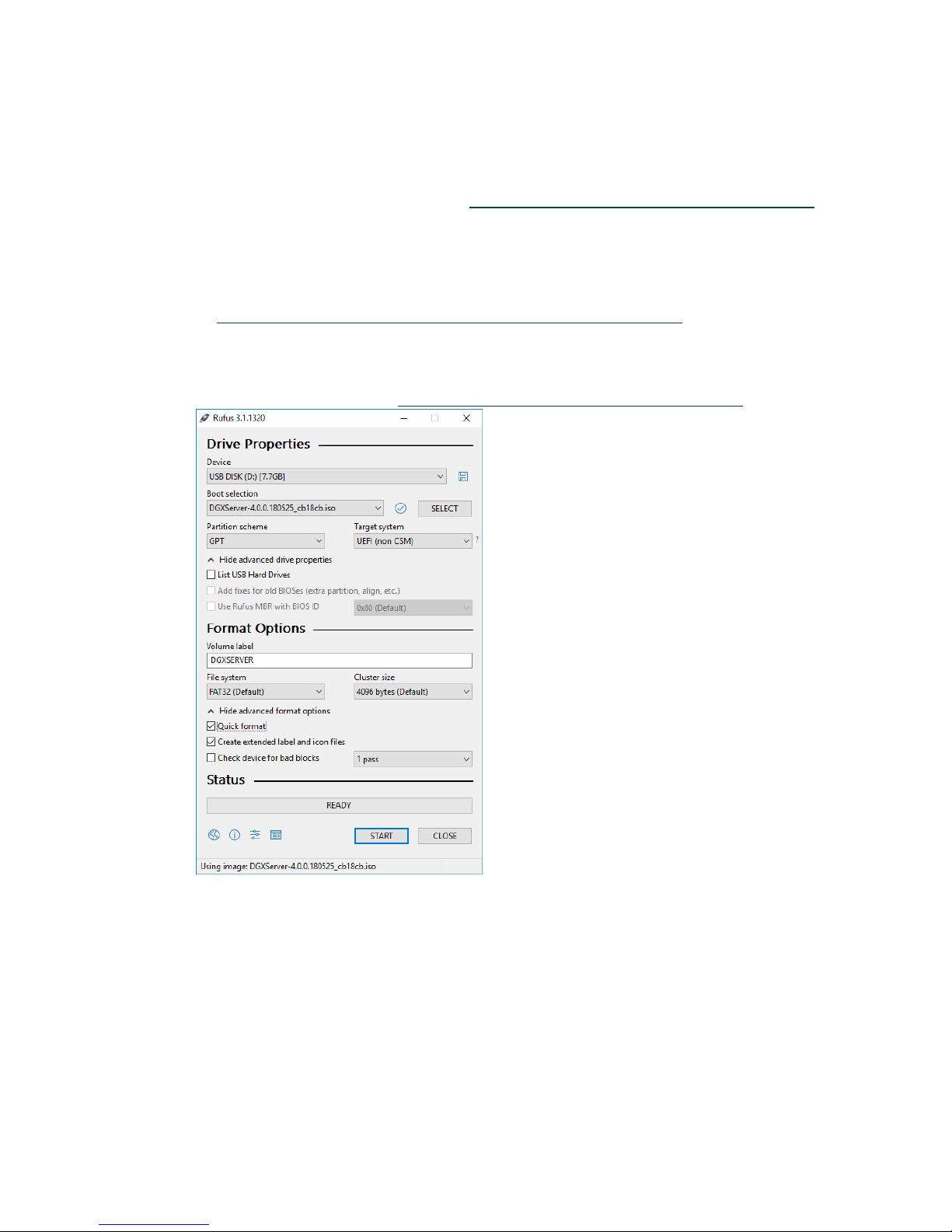
On a Windows system, you can use the Akeo Reliable USB Formatting Utility (Rufus) to
create a bootable USB flash drive that contains the DGX-2 software image.
Ensure that the following prerequisites are met:
The correct DGX-2 software image is saved to your local disk. For more information,
see Obtaining the DGX-2 Software ISO Image and Checksum File
The USB flash drive has a capacity of at least 4 GB.
1. Plug the USB flash drive into one of the USB ports of your Windows system.
2. Download and launch the Akeo Reliable USB Formatting Utility (Rufus).
.
3. Under Boot selection, click SELECT and then locate and select the ISO image.
4. Under Partition scheme, select GPT.
5. Under File system, select FAT32.
6. Click Start. Because the image is a hybrid ISO file, you are prompted to select
whether to write the image in ISO Image (file copy) mode or DD Image (disk image)
DGX-2 System User Guide
50
Page 51

mode.
7. Select Write in ISO Image mode and click OK.
Restoring the DGX-2 Software Image
RE-IMAGING THE SYSTEM FROM A USB FLASH
DRIVE
These instructions describe how to re-image the system from a USB flash drive. For
information about how to restore the system remotely, see
Remotely.
Before re-imaging the system from a USB flash drive, ensure that you have a bootable
USB flash drive that contains the current
1. Plug the USB flash drive containing the OS image into the DGX-2 System.
2. Connect a monitor and keyboard directly to the DGX-2 System.
3. Boot the system and press F11 when the NVIDIA logo appears to get to the boot
menu.
4. Select the USB volume name that corresponds to the inserted USB flash drive, and
boot the system from it.
5. When the system boots up, select Install DGX Server on the startup screen.
If you are an advanced user who is not using the RAID disks as cache and want to
keep data on the RAID disks, then select
RAID.
See the section Retaining the RAID Partition While Installing the OS for more
information.
Re-Imaging the System
DGX-2 software image.
Install DGX Server without formatting
6. Press Enter.
The DGX-2 System will reboot and proceed to install the image. This can take more
than 15 minutes.
Note: The Mellanox InfiniBand driver installation may take up to 10 minutes.
DGX-2 System User Guide
51
Page 52

Restoring the DGX-2 Software Image
After the installation is completed, the system then reboots into the OS.
Refer to Setting Up the DGX-2 System
for the steps to take when booting up the DGX-2
System for the first time after a fresh installation.
RETAINING THE RAID PARTITION WHILE
INSTALLING THE OS
The re-imaging process creates a fresh installation of the DGX OS. During the OS
installation or re-image process, you are presented with a boot menu when booting the
installer image. The default selection is
then repartitions all the SSDs, including the OS SSD as well as the RAID SSDs, and the
RAID array is mounted as /raid. This overwrites any data or file systems that may exist
on the OS disk as well as the RAID disks.
Since the RAID array on the DGX-2 System is intended to be used as a cache and not for
long-term data storage, this should not be disruptive. However, if you are an advanced
user and have set up the disks for a non-cache purpose and want to keep the data on
those drives, then select the
boot menu during the boot installation. This option retains data on the RAID disks and
performs the following:
Install DGX Server without formatting RAID option at the
Install DGX Software. The installation process
Installs the cache daemon but leaves it disabled by commenting out the RUN=yes line
in /etc/default/cachefilesd.
Creates a /raid directory, leaves it out of the file system table by commenting out the
entry containing “/raid” in /etc/fstab.
Does not format the RAID disks.
When the installation is completed, you can repeat any configurations steps that you
had performed to use the RAID disks as other than cache disks.
You can always choose to use the RAID disks as cache disks at a later time by
enabling
1. Uncomment the #RUN=yes line in /etc/default/cachefiled.
2. Uncomment the /raid line in etc/fstab.
3. Run the following:
cachefilesd and adding /raid to the file system table as follows:
a) Mount /raid.
sudo mount /raid
b) Start the cache daemon.
DGX-2 System User Guide
52
Page 53

systemctl start cachefilesd
These changes are preserved across system reboots.
Restoring the DGX-2 Software Image
DGX-2 System User Guide
53
Page 54

UPDATING THE DGX OS SOFTWARE
You must register your DGX-2 System in order to receive email notification whenever a
new software update is available.
These instructions explain how to update the DGX-2 software through an internet
connection to the NVIDIA public repository. The process updates a DGX-2 System
image to the latest QA’d versions of the entire DGX-2 software stack, including the
drivers.
CONNECTIVITY REQUIREMENTS FOR
SOFTWARE UPDATES
Before attempting to perform the update, verify that the DGX-2 System network
connection can access the public repositories and that the connection is not blocked by a
firewall or proxy.
Enter the following on the DGX-2 System.
$ wget -O f1-changelogs http://changelogs.ubuntu.com/meta-release-lts
$ wget -O f2-archive
http://archive.ubuntu.com/ubuntu/dists/bionic/Release
$ wget -O f3-usarchive
http://us.archive.ubuntu.com/ubuntu/dists/bionic/Release
$ wget -O f4-security
http://security.ubuntu.com/ubuntu/dists/bionic/Release
$ wget -O f5-download
http://download.docker.com/linux/ubuntu/dists/bionic/Release
$ wget -O f6-international
http://international.download.nvidia.com/dgx/repos/dists/bionic/Release
DGX-2 System User Guide
54
Page 55
Updating the DGX OS Software
!
All the wget commands should be successful and there should be six files in the
directory with non-zero content.
UPDATE INSTRUCTIONS
CAUTION: These instructions update all software for which updates are available from
your configured software sources, including applications that you installed yourself. If
you want to prevent an application from being updated, you can instruct the Ubuntu
package manager to keep the current version. For more information, see Introduction
to Holding Packages on the Ubuntu Community Help Wiki.
Perform the updates using commands on the DGX-2 console.
1. Run the package manager.
$ sudo apt update
2. Check to see which software will get updated.
$ sudo apt full-upgrade -s
To prevent an application from being updated, instruct the Ubuntu package manager
to keep the current version. See Introduction to Holding Packages
3. Upgrade to the latest version.
$ sudo apt full-upgrade
.
Answer any questions that appear.
Most questions require a Yes or No response. If asked to select the grub configuration
to use, select the current one on the system.
Other questions will depend on what other packages were installed before the update
and how those packages interact with the update. Typically, you can accept the
default option when prompted.
4. Reboot the system.
DGX-2 System User Guide
55
Page 56

UPDATING FIRMWARE
This section provides instructions for updating firmware for the NVIDIA® DGX server
BIOS and BMC using a Docker container.
GENERAL FIRMWARE UPDATE GUIDELINES
Before updating the firmware, do the following to prevent corrupting the firmware
due to a system crash or disruption to the update process.
● Ensure the system is healthy
● Stop system activities
Do not terminate the firmware update console while updating the firmware.
Component firmware corruption may occur if the update process is interrupted.
Certain components, such as the system BIOS, require a system reboot for the new
firmware to take effect.
Reboot the system if prompted.
When updating the BMC firmware, system management services are shut down first
to allow the update to occur. Consequently, system management is not available
during the BMC update.
In the event of a firmware update failure, run nvsm dump health and then send
the resulting archive containing the output to NVIDIA Enterprise Support
(https://nvid.nvidia.com/dashboard/
Do not attempt any further firmware updates until the issue is resolved or cleared
by NVIDIA Enterprise Support.
) for failure analysis.
DGX-2 System User Guide
56
Page 57

OBTAINING THE FIRMWARE UPDATE
Updating Firmware
CONTAINER
1. Obtain the container tarball from the NVIDIA Enterprise Support portal and transfer it
to the DGX-2 System.
The container is provided in the tarball <image-name>.tar.gz.
2. From the directory where you copied the tarball file, enter the following command.
$ sudo docker load -i <image-name>.tar.gz
3. To verify that the container image is loaded, enter the following.
$ sudo docker images
Example output after loading nvfw-dgx2_18.09.3.tar.gz.
REPOSITORY TAG IMAGE ID CREATED SIZE
nvfw-dgx2_18.09.3 latest aa681a4ae600 1 hours ago 278MB
QUERYING THE FIRMWARE MANIFEST
The manifest displays a listing of firmware components embedded in the containers that
are qualified by NVIDIA.
To query the firmware manifest, enter the following:
# sudo docker run --rm --privileged -v /:/hostfs <image-name>
show_fw_manifest
QUERYING THE CURRENTLY INSTALLED
FIRMWARE VERSIONS
Display the onboard firmware version level of each component supported by the
container. The output will show which component firmware is up to date, or whether it
needs to be updated to the firmware level listed in the manifest.
To query the version information, enter the following.
DGX-2 System User Guide
57
Page 58

Updating Firmware
# sudo docker run --privileged -v /:/hostfs <image-name> show_version
The output shows the onboard version, the version in the manifest, and whether the
firmware is up-to-date.
UPDATING THE FIRMWARE
You can either update all the down-level firmware components at one time, or update
just one or more components.
9.5.1 Command Syntax
sudo docker run --rm [-e auto=1] --privileged -ti -v /:/hostfs <imagename> update_fw [-f] <target>
Where <target> specifies the hardware to update, and is either
all
to update all firmware components (SBIOS, BMC)
or one or more of the following:
SBIOS
to update the SBIOS
BMC
to update the BMC firmware
Note: Other components may be supported beyond those listed here. Query the
firmware manifest to see all the components supported by the container.
The command will scan the specified firmware components and update any that are
down-level.
See the section Additional Options for an explanation of the [-e auto=1] and [-f]
options.
DGX-2 System User Guide
58
Page 59

Updating Firmware
9.5.2 Updating All Firmware components
The following instructions are an example of attempting to update all the firmware
components using the container nvfw-dgx2_18.09.3. In this example, the SBIOS and
BMC require an update.
1. Enter the following.
$ sudo docker run --rm --privileged -ti -v /:/hostfs nvfwdgx2_18.09.3 update_fw all
The container will scan the components and then prompt for confirmation before
starting the update.
Following components will be updated with new firmware version:
SBIOS
BMC
IMPORTANT: Firmware update is disruptive and may require system
reboot.
Stop system activities before performing the update.
Ok to proceed with firmware update? <Y/N>
2. Press Y to proceed.
The firmware update progress is displayed for each component.
Note: While the progress output shows the current and manifest firmware versions, the
versions may be truncated due to space limitations. You can confirm the updated
version after the update is completed using the show_version option.
When the update completes successfully, the following message is displayed.
Firmware update completed Component: SBIOS, update status: success,
reboot required: yes
Component: BMC, update status: success, new version: 3.20.30
3. If directed by the update message, reboot the system.
9.5.3 Updating Specific Firmware Components
The following is an example of updating the SBIOS firmware using the container nvfw-
dgx2_18.09.3.
1. Enter the following.
$ sudo docker run --rm --privileged -ti -v /:/hostfs nvfwdgx2_18.09.3 update_fw SBIOS
The container will scan the components and then prompt for confirmation before
starting the update.
Following components will be updated with new firmware version:
IMPORTANT: Firmware update is disruptive and may require system
reboot.
Stop system activities before performing the update.
DGX-2 System User Guide
59
Page 60

Updating Firmware
Ok to proceed with firmware update? <Y/N>
2. Press Y to proceed. When the update completes successfully, the following message is
displayed.
Firmware update completed
Component: SBIOS, update status: success, reboot required: yes
You can also update a subset of all the components. For example, to update both the
BMC firmware and the system BIOS, enter the following:
$ sudo docker run --rm --privileged -ti -v /:/hostfs nvfw-dgx2_18.09.3
update_fw BMC SBIOS
9.5.4 Updating Firmware for Individual NVMe or PSU
units
To update firmware for an individual PSU or NMVe unit, use the -s option along with
the component ID, where the PSU component ID is 1 – 6, and the NVMe component ID
is the nvme device name.
Example of updating the firmware for PSU 5:
$ sudo docker run --rm --privileged -ti -v /:/hostfs nvfw-dgx2_18.10.2
update_fw PSU -s 5
Example of updating the firmware for nvme0n1:
$ sudo docker run --rm --privileged -ti -v /:/hostfs nvfw-dgx2_18.10.2
update_fw SSD -s nvme0n1
ADDITIONAL OPTIONS
9.6.1 Forcing the Firmware Update
To update the firmware regardless of whether it is down-level, use the -f option as
follows.
$ sudo docker run --rm --privileged -ti -v /:/hostfs <image-name>
update_fw -f <target>
The container will not check the onboard versions against the manifest.
DGX-2 System User Guide
60
Page 61

Updating Firmware
9.6.2 Updating the Firmware Non-interactively
The standard way to run the container is interactively (-ti option). The container will
prompt you to confirm before initiating the update.
To update the firmware without encountering the prompt, omit the -ti option and
instead use the -e auto=1 and -t options as follows.
$ sudo docker run -e auto=1 --rm --privileged -t -v /:/hostfs <image-
name> update_fw <target>
COMMAND SUMMARY
Show the manifest.
$ sudo docker run --rm --privileged -v /:/hostfs <image-name>
show_fw_manifest
Show version information.
$ sudo docker run --rm --privileged -v /:/hostfs <image-name>
show_version
Check the onboard firmware against the manifest and update any down-level
firmware.
$ sudo docker run --rm --privileged -ti -v /:/hostfs <image-name>
update_fw <target>
Bypass the version check and update the firmware.
$ sudo docker run --rm --privileged -ti -v /:/hostfs <image-name>
update_fw -f <target>
Update the firmware in non-interactive mode.
$ sudo docker run --rm -e auto=1 --privileged -t -v /:/hostfs <image-
name> update_fw <target>
Update the firmware for an individual PSU or NVme.
$ sudo docker run --rm -e auto=1 --privileged -t -v /:/hostfs <image-
name> update_fw <PSU | SSD> -s <component-id>
REMOVING THE CONTAINER
Remove the container and image from the DGX server when it is no longer needed. To
remove the container and image, enter the following:
$ sudo docker rmi -f <image-name>
In this case, specify only the container repository and not the tag.
DGX-2 System User Guide
61
Page 62

USING THE BMC
The NVIDIA DGX-2 System comes with a baseboard management controller (BMC) for
monitoring and controlling various hardware devices on the system. It monitors system
sensors and other parameters.
CONNECTING TO THE BMC
1. Make sure you have connected the BMC port on the DGX-2 System to your LAN.
2. Open a browser within your LAN and go to:
https://<ipmi-ip-address>/
Make sure popups are allowed for the BMC address.
DGX-2 System User Guide
62
Page 63

3. Log in.
Using the BMC
OVERVIEW OF BMC CONTROLS
The left-side navigation menu on the BMC dashboard contains the primary controls.
DGX-2 System User Guide
63
Page 64
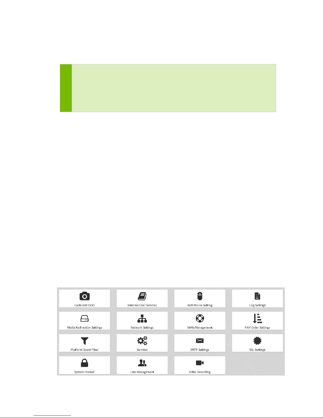
Using the BMC
10.2.1 QuickLinks …
Provides quick access to several tasks.
Note: Depending on the BMC firmware version, the following quick links may appear:
• Maintenance->Firmware Update
• Settings->NbMeManagement->NvMe P3700Vpd Info
Do not access these tasks using the Quick Links dropdown menu, as the resulting pages
are not fully functional.
10.2.2 Sensor
Provides status and readings for system sensors, such as SSD, PSUs, voltages, CPU
temperatures, DIMM temperatures, and fan speeds.
10.2.3 FRU Information
Provides, chassis, board, and product information for each FRU device.
10.2.4 Logs & Reports
Lets you view, and if applicable, download and erase, the IPMI even log, and system,
audit, video and POST Code logs.
10.2.5 Settings
Configure the following settings
DGX-2 System User Guide
64
Page 65

10.2.6 Remote Control
Opens the KVM Launch page for accessing the DGX-2 console remotely.
10.2.7 Power Control
Perform various power actions
Using the BMC
10.2.8 Maintenance
Note: While you can update the BMC firmware from this page, NVIDIA recommends
using the NVIDIA Firmware Update Container instead (see section Updating Firmware
for instructions). If you need to update from this page, click Dual Firmware Update
and then select the Both Images from the Images to be Updated menu.
The Both images option ensures that the primary image (Image1) and the backup
image (Image2) are updated. Image2 is used if there is a problem with Image1.
DGX-2 System User Guide
65
Page 66
USING DGX-2 SYSTEM IN KVM MODE
OVERVIEW
11.1.1 About NVIDIA KVM
The NVIDIA Kernel-based Virtual Machine (KVM) is a virtualization solution based on
the Linux Kernel Virtual Machine (https://www.linux-kvm.org
GPU multi-tenancy. Since the KVM Hypervisor is part of the Linux kernel on the DGX-2
System, it contains the system-level components necessary to support multi-tenancy on
the DGX-2 System, such as a memory manager, process scheduler, input/output (I/O)
stack, device drivers, security manager, and a network stack.
The following diagram depicts an overview of the NVIDIA KVM architecture, showing
the hardware layer, the DGX Server KVM OS, and the virtual machines.
) and enhanced to enable
DGX-2 System User Guide
66
Page 67
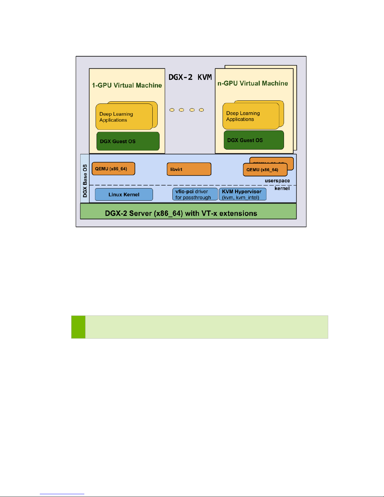
Using DGX-2 System in KVM Mode
Using NVIDIA KVM, the DGX-2 System can be converted to include a bare metal
hypervisor to provide GPU multi-tenant virtualization. This is referred to as the DGX-2
KVM host. It allows different users to run concurrent deep learning jobs using multiple
virtual machines (guest GPU VMs) within a single DGX-2 System. Just like the baremetal DGX-2 System, each GPU-enabled VM contains a DGX OS software image which
includes NVIDIA drivers, CUDA, the NVIDIA Container Runtime for Docker, and other
software components for running deep learning containers.
Note: Unlike the-bare metal DGX-2 system or the KVM host OS, the guest VM OS is
configured for English-only, and cannot be configured for other languages.
Running NVIDIA containers on the VM is just like running containers on a DGX-2 bare
metal system with DGX OS software installed.
While NVIDIA KVM turns your DGX system into a hypervisor supporting multiple
guest GPU VMs, it does not currently provide support for the following:
oVirt, virt-manager
The DGX-2 OS incorporates Ubuntu server, which does not include a graphics
manager required by oVirt and virt-manager.
Orchestration/resource manager
Created GPU VMs are static and cannot be altered once created.
DGX-2 System User Guide
67
Page 68

Using DGX-2 System in KVM Mode
NVMe drives as pass-through devices
To preserve the existing RAID configuration on the DGX-2 System and simplify the
process of reusing this resource if the server were ever to be reverted from KVM,
NVMe drives cannot be used as pass-through devices.
The DGX-2 KVM host cannot be used to run deep learning containers with GPUs.
NVIDIA GPUDirect
TM
is not supported on multi-GPU guest VMs over InfiniBand.
11.1.2 About the Guest GPU VM (Features and
Limitations)
Guest GPU VMs are based on an installed KVM image.
Guest GPU VM size and resources are based on the number of GPUs assigned
Once a GPU VM is created and resources assigned, reconfiguring the VM (adding or
removing GPUs, modifying other resource allocations) is not supported.
Access to the hardware is restricted from within the guest GPU VM such that
● GPUs cannot be reset
● GPU VBIOS cannot be updated
● System firmware (including Mellanox IB) upgrade is not supported
● There is no guest UEFI BIOS support
11.1.3 About nvidia-vm
Guest GPU VMs can be managed using the virsh (see https://linux.die.net/man/1/virsh)
program or using libvirt-based XML templates. For the NVIDIA KVM, NVIDIA has
taken the most common virsh options and configuration steps and incorporated them
into the tool nvidia-vm, provided with the DGX KVM package. nvidia-vm simplifies
the process of creating guest GPU VMs and allocating resources. In addition, you can
use nvidia-vm to modify default options to suit your needs for the VM and manage
VM images installed on the system.
To view the top-level help, enter the following.
nvidia-vm --help
You can view the man pages by entering the following from the DGX-2 KVM host.
man nvidia-vm
Details of basic commands are provided in the following sections.
DGX-2 System User Guide
68
Page 69
Using DGX-2 System in KVM Mode
!
PRELIMINARY SETUP - CONVERTING THE
DGX-2 SYSTEM TO A DGX-2 KVM HOST
To operate VMs from the DGX-2 System, you must first convert the DGX-2 System to a
DGX-2 KVM host. Do this by installing the DGX KVM Software package and the DGX
KVM image.
Perform the following steps on the command line of the DGX-2 System.
1. Update the package list.
sudo apt-get update
2. Check available DGX KVM images.
sudo apt-cache policy dgx-kvm-image*
This returns a list of images in the repository.
3. Install the dgx-kvm-sw package as well as one of the images listed in the previous
step.
sudo apt-get install dgx-kvm-sw <dgx-kvm-image-x-y-z>
Example of selecting image dgx-kvm-image-4-0-1:
sudo apt-get install dgx-kvm-sw dgx-kvm-image-4-0-1
4. Reboot the system.
Rebooting the system is needed to finalize the KVM preparation of the DGX-2
System. It updates the GRUB menu options so the Linux kernel is made KVM-ready,
and binds the virtualization drivers to the NVIDIA devices
sudo reboot.
Your DGX-2 System is now ready for you to create VMs.
Restoring to Bare Metal
After setting up the DGX-2 System as a KVM host, you can restore the server to a bare
metal system.
CAUTION: Reverting the server back to a bare metal system destroys all guest GPU VMs
that were created as well as any data. Be sure to save your data before removing the
KVM software.
To restore the DGX-2 System to a bare metal system, do the following
1. Remove all the installed dgx-kvm-image packages.
Refer to the section Uninstalling Images for instructions.
DGX-2 System User Guide
69
Page 70

Using DGX-2 System in KVM Mode
2. Remove the meta package and all its dependencies.
sudo apt-get purge --auto-remove dgx-kvm-sw
3. Reboot the system.
sudo reboot
LAUNCHING A GUEST GPU VM INSTANCE
To create and delete guest GPU VMs, use the NVIDIA utility nvidia-vm which
simplifies the complex process of these tasks. For other VM management tasks, use virsh
where indicated in these instructions.
11.3.1 Determining the Guest GPU VMs on the DGX-2
System
GPUs cannot be assigned to more than one VM. Therefore, before you can create a VM
that uses one or more GPUs, you must determine the number and position of the GPUs
that are already allocated to VMs.
Run the following command.
virsh list
The domain of each guest GPU VM is either based on the username of the VM creator
appended with a timestamp, or is specified by the VM creator. The domain is then
appended with a suffix to indicate the number of GPUs and their indices using the
format
<number-of-gpus>g<starting-index>-<ending index>.
Examples:
my-lab-vm1-8g0-7 : This VM is assigned 8 GPUs from index 0 through 7
my-lab-vm2-1g0 : This VM is assigned 1 GPU from index 0
my-lab-vm3-4g8-11 : This VM is assigned 4 GPUs from index 8 through 11
Inspect the list to determine the GPU indices that are available to you.
DGX-2 System User Guide
70
Page 71
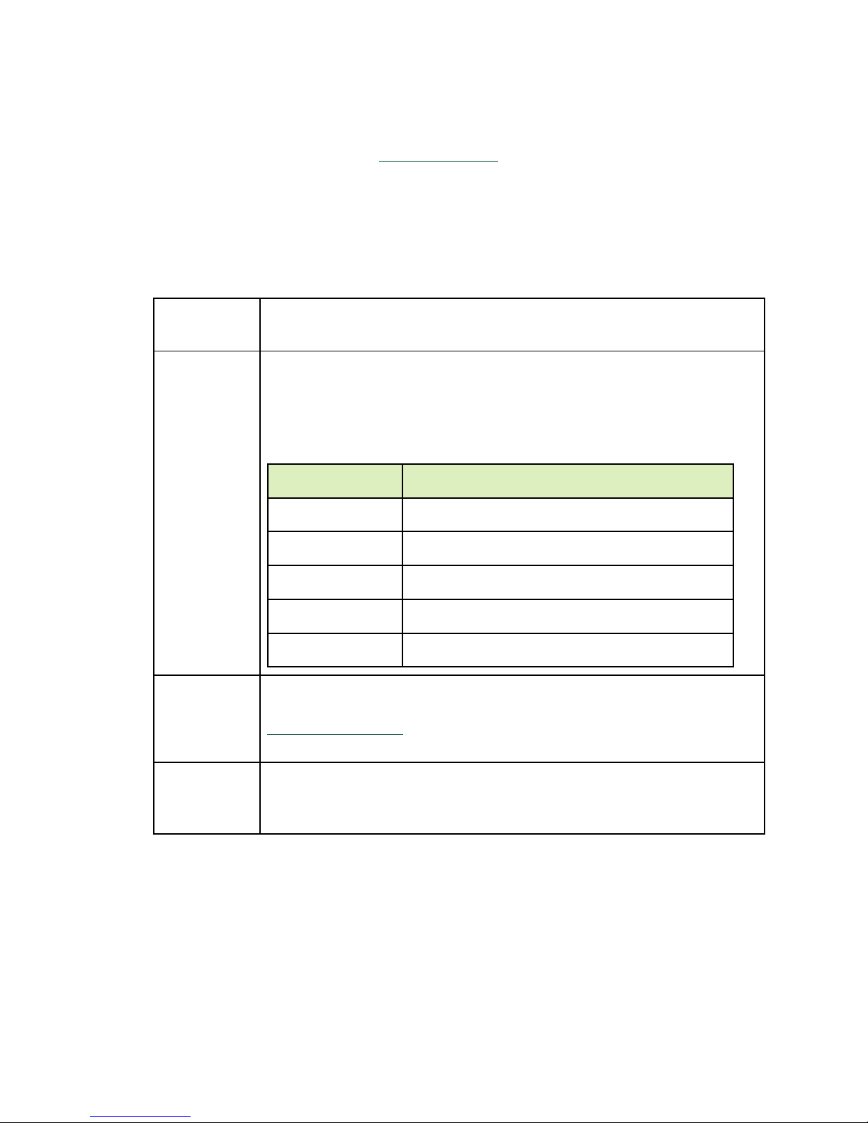
Using DGX-2 System in KVM Mode
--gpu-count
--gpu-index
Number of GPUs
Allowed values for gpu_index
1
0,1,2,3,4,5,6,7,8,9,10,11,12,13,14,15
2
0,2,4,6,8,10,12,14
4
0,4,8,12
8
0,8
16
0
--image
[options]
11.3.2 Creating a VM Using Available GPUs
Use nvidia-vm as explained in About nvidia-vm.
Syntax
nvidia-vm create --gpucount N --gpu-index X [--image] [options]
where
The allowed number of GPUs to assign to the VM, depending on availability.
Acceptable values: 1, 2, 4, 8, 16
For the purposes of the KVM, GPUs on the DGX-2 System are
distinguished by a zero-based, sequential index. gpu_index specifies the
starting index value for the group of sequentially indexed GPUs to be assigned
to the VM.
Allowed values for gpu_index depend on the number of GPUs assigned to the
VM, as shown in the following table.
(Optional) Specifies the KVM image to use as the basis for the VM. If not
specified, the latest version that is installed will be used. See the section
Managing the Images for instructions on how to install images and also how to
view which images are installed.
Optional parameters, including options to customize the default resource
allocation (vCPUs, memory, OS disk size):
See the man pages or the Help for a detailed list of options.
Command Help:
nvidia-vm create --help
Command Examples:
Basic command
DGX-2 System User Guide
71
Page 72
Using DGX-2 System in KVM Mode
nvidia-vm create --gpu-count 4 --gpu-index 12
This command creates a guest GPU VM with 4 GPUs, starting with index 12. Since no
domain was specified, the software generates a domain which incorporates the
username, day, hour, and minute. For example, jsmithTue1308-4g12-15.
Specifying a domain
nvidia-vm create --gpu-count 2 --gpu-index 8 --domain
mydgx2vm2
This command creates a VM with 2 GPUs, starting with index 8, named mydgx2vm2g8-9.
Specifying an image
nvidia-vm create --gpu-count 2 --gpu-index 2 --image dgx-kvmimage-4-0-1
This command creates a VM with 2 GPUs, starting with index 2, named
jsmithTue1308-2g2-3, and based on the image dgx-kvm-image-4-0-1.
STOPPING, RESTARTING, AND DELETING A
GUEST GPU VM
Once a guest GPU is created, it can be stopped if you want to temporarily free resources
while keeping your data. You can then restart the stopped guest GPU VM. You can also
permanently delete a guest GPU VM, which frees resources and deletes associated data.
11.4.1 Stopping a VM
You can stop a VM, which does the following:
Releases the CPUs, memory, GPUs, and NVLink
Retains allocation of the OS and data disks
Note: Since allocation of the OS and data disks are retained, the creation of other VMs
is still impacted by the stopped VM
To stop a VM, enter the following.
virsh shutdown <vm-domain>
DGX-2 System User Guide
72
Page 73

Using DGX-2 System in KVM Mode
!
!
If virsh shutdown fails to stop the VM, for example, if the VM OS is unresponsive,
you can force a VM shutdown as follows.
virsh destroy <vm-domain>
Like virsh shutdown, virsh destroy does not remove files or clear the OS disk
allocation, so the options for creating other VMs may still be impacted depending on
available disk space.
CAUTION: Only use virsh destroy as a last resort, since the command initiates an
ungraceful shutdown and may result in a corrupt VM file system.
11.4.2 Restarting a VM
To restart a VM that has been stopped (not deleted), run the following.
virsh start <vm-domain>
You can also connect to the console automatically upon restarting the VM using the
following command.
virsh start --console <vm-domain>
11.4.3 Deleting a VM
Like the process of creating a guest GPU VM, deleting a VM involves several virsh
commands. For this reason, NVIDIA provides a simple way to delete a VM using
nvidia-vm. Deleting a VM using nvidia-vm does the following:
Stops the VM if it is running
Erases data on disks that the VM is using and releases the disks
Deletes any temporary support files
You should delete your VM instead of merely stopping it in order to release all resources
and to remove unused files.
CAUTION: VMs that are deleted cannot be recovered. Be sure to save any data before
deleting any VMs.
DGX-2 System User Guide
73
Page 74

Using DGX-2 System in KVM Mode
Use nvidia-vm as explained in About nvidia-vm.
Syntax
nvidia-vm delete --domain <vm-domain>
Command Help
nvidia-vm delete --help
Command Examples
Deleting an individual VM
nvidia-vm delete --domain dgx2vm-labTue1308-4g12-15
Deleting all the VMs on the system
nvidia-vm delete --domain ALL
CONNECTING TO YOUR GUEST GPU VM
11.5.1 Determining IP Addresses
If you are using the default network configuration, you can determine the IP address of
your VM by entering the following.
virsh net-dhcp-leases default
NOTE: “virsh net-dhcp-leases default” may show a stale VM name for a newly created
VM, in which case the IP address for the new VM is not shown.
To work around, connect to the incorrectly named VM.
$ virsh console <vm-name>
Connected to domain <vm-name>
Then use the “ifconfig” command to find the IP address for the VM.
11.5.2 Connecting to the Guest GPU VM
You can connect to your VM in the following ways.
Option 1 (connecting to the VM from the Host OS)
DGX-2 System User Guide
74
Page 75

virsh console <vm-domain>
NOTE: This command will not work right away for a non-GPU guest VM.
To resolve, reset the guest VM using either
$ virsh reboot
or
$ virsh reset
Option 2 (connecting to the VM using SSH)
ssh <username>@IP ADDRESS
The default credentials for logging into the VM are -
Using DGX-2 System in KVM Mode
Login: nvidia
Password: nvidia
These can be changed. See the section Changing Login Credentials for instructions.
11.5.3 Making Your VM More Secure
There are a couple of things you can do to make your VM more secure.
Change the Login Credentials
Add SSH Keys
11.5.4 Changing Login Credentials
When the guest GPU VM is created, the default login credentials are nvidia/nvidia. As a
security practice, use the standard Ubuntu methods to create a new user account and
then delete the nvidia user account from the GPU VM. The basic commands are
provided below for convenience. Consult the Ubuntu/Linux documentation for
additional options.
Creating a new user account
sudo useradd -m <new-username> -p <new-password>
Deleting the nvidia user account
deluser -r nvidia
To run virsh commands, the new user must then be added to the libvirt group.
DGX-2 System User Guide
75
Page 76

Using DGX-2 System in KVM Mode
sudo usermod -a -G libvirt <new-username>
11.5.5 Adding SSH Keys
You can incorporate SSH keys to increase security over password authentication.
Refer to the following websites for instructions.
How to set up SSH so you aren't asked for a password
How to disable password authentication
MANAGING IMAGES
Guest GPU VMs are based on an installed KVM image. You can manage these images
as explained in this section.
Use nvidia-vm as explained in About nvidia-vm
Syntax
nvidia-vm image [options]
This section describes common command options.
Command Help
nvidia-vm image --help
.
11.6.1 Installing Images
The KVM image is typically installed at the time the KVM package is installed. Since
updated KVM images may be available from the repository, you can install any of these
images for use in creating a guest GPU VM.
To check available DGX KVM images, enter the following.
apt-cache policy dgx-kvm-image
This returns a list of images in the repository.
To install a KVM image from the list, use the nvidia-vm image install command.
Syntax
nvidia-vm image install <vm-image>
DGX-2 System User Guide
76
Page 77

Using DGX-2 System in KVM Mode
Example
nvidia-vm image install dgx-kvm-image-4-0-1
11.6.2 Viewing a List of Installed Images
To view a list of all the VM images that are installed in the guest OS image directory,
enter the following.
nvidia-vm image show
11.6.3 Viewing Image Usage
To view a list of created VMs and the images they are using, enter the following.
nvidia-vm image vmshow
11.6.4 Uninstalling Images
If you convert the DGX-2 System from a KVM OS back to the bare metal system, you
need to uninstall all the dgx-kvm images that were installed.
Perform the following for each installed image.
nvidia-vm image uninstall dgx-kvm-image-x-y-z
Ok to remove image package "dgx-kvm-image-4-0-1"? (y/N) :
where x-y-z is the version for each installed image.
USING THE GUEST OS DRIVES AND DATA
DRIVES
The figure below depicts how NVIDIA KVM generates the Guest OS Drive and Data
Drive from the physical drives on the DGX-2 System.
DGX-2 System User Guide
77
Page 78

Using DGX-2 System in KVM Mode
11.7.1 Guest OS Drive
DGX-2 KVM Host software uses the existing RAID-1 volume as the OS drive of each
Guest (/dev/vda1) which by default is 50 GB. Since the OS drive resides on the RAID-1
array of the KVM Host, its data shall always be persistent.
Using the nvidia-vm tool, a system administrator can change the default OS drive size.
11.7.2 Data Drives
The DGX-2 KVM host software assigns a virtual disk to each guest GPU VM, referred to
here as the Data Drive. It is based on filesystem directory-based volumes and can be
used either as scratch space or as a cache drive.
DGX-2 software sets up a storage pool on top of the existing RAID-0 volume on the
KVM Host for Data Drives on the Guests. The Data drive is automatically carved, by
nvidia-vm tool, out of the Storage Pool and allocated to each GPU VM as a Data Drive
(/dev/vdb1) which is automatically mounted on /raid. The Data Drive size is preconfigured according to the size of the GPU VM. For example, a 16-GPU VM gets a very
large Data Drive (See the Resource Allocation
section for size details).
DGX-2 System User Guide
78
Page 79

Using DGX-2 System in KVM Mode
dgx-kvm-pool active yes
52:54:00:16:b9:ff ip: 192.168.122.126
vol-dgx2vm-labTue1209-1g0 /raid/vol-dgx2vm-labTue1209-1g0 file 54.85 GiB 1.11 GiB
Since the Data Drive is created on the Host RAID-0 array, data is not intended to be
persistent. Therefore, when the GPU VM is destroyed, the Data Drive is automatically
deleted and data is not preserved.
Using the nvidia-vm tool, a system administrator can change the default Data Drive size.
11.7.3 Storage Pool Demonstration
This section shows how to view the storage pool, and how disk space is assigned to a
VM from the storage pool.
Show storage pool
Enter the following to verify the storage pool is active.
$ virsh pool-list
Name State Autostart
-------------------------------------------
Create a VM:
$ nvidia-vm create --gpu-count 1 --gpu-index 0
dgx2vm-labTue1209-1g0: create start vnc: 0.0.0.0:0 mac:
Viewing the Volume from the DGX-2 KVM Host
To see the volumes that are created for each VM, enter the following.
$ virsh vol-list dgx-kvm-pool --details
Name Path Type Capacity Allocation
-----------------------------------------------------------------------------------------
Viewing the Data Volume from the Guest VM
DGX-2 System User Guide
79
Page 80

1. Connect to the guest GPU VM.
Connected to domain dgx2vm-labTue1209-1g0
nvidia@dgx2vm-labTue1209-1g0:~$
$ virsh console dgx2vm-labTue1209-1g0
2. List the virtual storage on the guest GPU VM.
nvidia@dgx2vm-labTue1209-1g0:~$ lsblk
NAME MAJ:MIN RM SIZE RO TYPE MOUNTPOINT
vda 252:0 0 50G 0 disk
└─vda1 252:1 0 50G 0 part /
vdb 252:16 0 54.9G 0 disk
└─vdb1 252:17 0 54.9G 0 part /raid
Using DGX-2 System in KVM Mode
UPDATING THE SOFTWARE
11.8.1 Updating the Host OS
You can update the DGX OS software for the host using standard Ubuntu apt process
with an internet connection.
Since the reboot step will stop any running guest VMs, they should be stopped first to
avoid an uncontrolled or unexpected interruption.
Perform the following from the host OS.
1. Update the list of available packages and their versions.
$ sudo apt update
2. Review the packages that will be updated.
$ sudo apt full-upgrade -s
To prevent an application from being updated, instruct the Ubuntu package
manager to keep the current version. See Introduction to Holding Packages.
3. Upgrade to the latest version.
$ sudo apt full-upgrade
● Answer any questions that appear.
DGX-2 System User Guide
80
Page 81

Using DGX-2 System in KVM Mode
― Most questions require a Yes or No response. When asked to select the grub
configuration to use, select the current one on the system.
― Other questions will depend on what other packages were installed before the
update and how those packages interact with the update.
● If a message appears indicating that nvidia-docker.service failed to start, you can
disregard it and continue with the next step. The service will start normally at that
time.
4. Reboot the system.
11.8.2 Updating the Guest VM OS
You can update the DGX OS software for the guest VM using standard Ubuntu apt
process with an internet connection. This is the same process that is used when updating
the DGX OS software on the bare metal system.
Perform the following from the guest VM.
1. Update the list of available packages and their versions.
$ sudo apt update
2. Review the packages that will be updated.
$ sudo apt full-upgrade -s
To prevent an application from being updated, instruct the Ubuntu package manager
to keep the current version. See Introduction to Holding Packages.
3. Upgrade to the latest version.
$ sudo apt full-upgrade
● Answer any questions that appear.
― Most questions require a Yes or No response. When asked to select the grub
configuration to use, select the current one on the system.
― Other questions will depend on what other packages were installed before the
update and how those packages interact with the update.
● If a message appears indicating that nvidia-docker.service failed to start, you can
disregard it and continue with the next step. The service will start normally at that
time.
4. Reboot the guest VM.
$ sudo reboot
DGX-2 System User Guide
81
Page 82

Using DGX-2 System in KVM Mode
GPU
1 2 4 8 16
vCPU/HT
5
11
23
46
92
Memory (GB)
92
185
372
739
1478
InfiniBand
1 2 4 8 OS Drive (GB)
50
50
50
50
50
Data Drive (TB)
1.92
3.84
7.68
15.36
31.72
NVLink
N/A
1 3 6
6
SUPPLEMENTAL INFORMATION
11.9.1 Resource Allocations
By default, the KVM software assigns the following resources in approximate
proportion to the number of assigned GPUs:
Data drive values indicate the maximum space that will be used. The actual space is
allocated as needed.
You can use command options to customize memory allocation, OS disk size, and
number of vCPUs to assign.
11.9.2 Resource Management
NVIDIA KVM optimizes resources to maximize the performance of the VM.
vCPU
vCPUs are pinned to each VM to be NUMA-aware and to provide better VM
performance.
InfiniBand
IB ports are set up as passthrough devices to maximize performance.
GPU
GPUs are set up as passthrough devices to maximize performance.
Data Drive
Data drives are intended to be used as scratch space cache.
DGX-2 System User Guide
82
Page 83

Using DGX-2 System in KVM Mode
NVSwitch
NVSwitch assignments are optimized for NVLink peer-to-peer performance.
NVLink
An NVLink connection is the connection between each GPU and the NVSwitch fabric.
Each NVLink connection allows up to 25 GB/s uni-directional performance.
11.9.3 NVIDIA KVM Security Considerations
Consult the security policies of your organization to determine firewall needs and
settings.
11.9.4 Launching VMs in Degraded Mode
On DGX-2 KVM systems, degraded mode is a mechanism that allows one or more GPUs
to fail without affecting the operation or creation of other VMs on the server. This allows
the DGX-2 System to run GPU VMs with fewer than 16 GPUs present. System
administrators can then keep a subset of GPU VMs available for use while waiting to
replace GPUs that may have failed.
When the DGX-2 is Put in Degraded Mode
The following are the type of GPU errors that will put the system in degraded mode:
GPU double-bit ECC errors
GPU failure to enumerate on the PCIe bus
GPU side NVLink training error
GPU side unexpected XID error
To identify failed GPUs, the KVM host automatically polls the state of all GPUs in the
system at various times:
When the DGX-2 System boots, to capture the initial state of the GPUs
On a nightly basis
Upon launching a VM
When a failed GPU is identified by the software, the DGX-2 System is marked as
‘degraded’ and operates in degraded mode until all bad GPUs are replaced.
Creating VMs with the DGX-2 System in Degraded Mode
You can still create guest GPU VMs on a DGX-2 System in degraded mode as long as
you do not try to assign a failed GPU. If you attempt to create a VM with a failed GPU
DGX-2 System User Guide
83
Page 84

Using DGX-2 System in KVM Mode
after its state has been marked as ‘bad’ by the system, the VM will fail to start and an
appropriate error message is returned. Restarting an existing VM after a GPU fails will
result in the same failure and error message.
The following is an example of launching a VM when GPU 12 and 13 have been marked
as degraded or in a failed state.
nvidia-vm create --gpu-count 8 --gpu-index 8
ERROR: GPU 12 is in unexpected state "missing", can't use it BDF:e0:00.0 SXMID:13 UUID:GPU-b7187786-d894-2266-d11d-21124dc61dd3
ERROR: GPU 13 is in unexpected state "missing", can't use it BDF:e2:00.0 SXMID:16 UUID:GPU-9a6a6a52-c6b6-79c3-086b-fcf2d5b1c87e
ERROR: 2 GPU's are unavailable, unable to start this VM "dgx2vmlabMon1559-8g8-15"
Note: If you attempt to launch a VM with a failed GPU before the system has
identified its failed state, the VM will fail to launch but without an error
message. If this happens, keep trying to launch the VM until the message
appears.
Restarting a VM After the System or VM Crashes
Some GPU errors may cause the VM or the system to crash.
If the system crashes, you can attempt to restart the VM.
If the VM crashes (but not the system), you can attempt to restart the VM.
Your VM should restart successfully if none of the associated GPUs failed. However, if
one or more of the GPUs associated with your VM failed, then the response depends on
whether the system has had a chance to identify the GPU as unavailable.
Failed GPU identified as unavailable
The system will return an error indicating that the GPU is missing or unavailable and
that the VM is unable to start.
Failed GPU not yet identified as unavailable
The VM crashes upon being restarted.
Restoring a System from Degraded Mode
All GPUs need to be replaced to restore the DGX-2 from degraded mode.
DGX-2 System User Guide
84
Page 85

Using DGX-2 System in KVM Mode
The server must be powered off when performing the replacement. After GPU
replacement and upon powering on the server, the KVM software runs a health scan to
add any new GPUs to the health database.
DGX-2 System User Guide
85
Page 86

APPENDIX A.
INSTALLING SOFTWARE ON AIR-GAPPED
DGX-2 SYSTEMS
For security purposes, some installations require that systems be isolated from the
internet or outside networks. Since most DGX-2 software updates are accomplished
through an over-the-network process with NVIDIA servers, this section explains how
updates can be made when using an over-the-network method is not an option. It
includes a process for installing Docker containers as well.
A.1. Installing NVIDIA DGX-2 Software
One method for updating DGX-2 software on an air-gapped DGX-2 System is to
download the ISO image, copy it to removable media and then re-image the DGX-2
System from the media. This method is available only for software versions that are
available as ISO images for download.
Alternately, you can update the DGX-2 software by performing a network update from
a local repository. This method is available only for software versions that are available
for over-the-network updates.
DGX-2 System User Guide
86
Page 87

Using DGX-2 System in KVM Mode
!
A.2. Re-Imaging the System
CAUTION: This process destroys all data and software customizations that you
have made on the DGX-2 System. Be sure to back up any data that you want to
preserve, and push any Docker images that you want to keep to a trusted
registry.
1. Obtain the ISO image from the Enterprise Support site.
a) Log on to the NVIDIA Enterprise Support site and click the Announcements tab to
locate the DGX OS Server image ISO file.
b) Download the image ISO file.
2. Refer to the instructions in the Restoring the DGX-2 Software Image section for
additional instructions.
A.3. Creating a Local Mirror of the NVIDIA and
Canonical Repositories
Instructions for setting up a private repository or mirroring the NVIDIA and Canonical
repositories are beyond the scope of this document. It is expected that users are
knowledgeable about those processes.
1. Create a private repository that mirrors the NVIDIA as well as the Canonical
repositories
Consult /etc/apt/sources.list and the contents of
/etc/apt/sources.list.d on your running DGX-2 for the repository locations.
2. Modify /etc/apt/sources.list and appropriate contents of
/etc/apt/sources.list.d to point to your private repository.
3. Perform the update from the private repository, starting with Get the new package
list step (sudo apt-get update) of the instructions found in the DGX-2 Software
Release Notes and Upgrade Guide, which you can obtain from the Enterprise Support
site.
.
DGX-2 System User Guide
87
Page 88

Using DGX-2 System in KVM Mode
A.4. Installing Docker Containers
This method applies to Docker containers hosted on the NVIDIA NGC Container
Registry, and requires that you have an active NGC account.
1. On a system with internet access, log in to the NGC Container Registry by entering the
following command and credentials.
$ docker login nvcr.io
Username: $oauthtoken
Password: apikey
Type “$oauthtoken” exactly as shown for the Username. This is a special username
that enables API key authentication. In place of apikey, paste in the API Key text that
you obtained from the NGC website.
2. Enter the docker pull command, specifying the image registry, image repository, and
tag:
$ docker pull nvcr.io/nvidia/repository:tag
3. Verify the image is on your system using docker images.
$ docker images
4. Save the Docker image as an archive. .
$ docker save nvcr.io/nvidia/repository:tag > framework.tar
5. Transfer the image to the air-gapped system using removable media such as a USB flash
drive.
6. Load the NVIDIA Docker image.
$ docker load –i framework.tar
7. Verify the image is on your system.
$ docker images
.
DGX-2 System User Guide
88
Page 89

APPENDIX B. SAFETY
B.1. Safety Information
To reduce the risk of bodily injury, electrical shock, fire, and equipment damage, read
this document and observe all warnings and precautions in this guide before installing
or maintaining your server product.
In the event of a conflict between the information in this document and information
provided with the product or on the website for a particular product, the product
documentation takes precedence.
Your server should be integrated and serviced only by technically qualified persons.
You must adhere to the guidelines in this guide and the assembly instructions in your
server manuals to ensure and maintain compliance with existing product certifications
and approvals. Use only the described, regulated components specified in this guide.
Use of other products I components will void the UL Listing and other regulatory
approvals of the product, and may result in noncompliance with product regulations in
the region(s) in which the product is sold.
DGX-2 System User Guide
89
Page 90

Using DGX-2 System in KVM Mode
B.2. Safety Warnings and Cautions
To avoid personal injury or property damage, before you begin installing the product,
read, observe, and adhere to all of the following safety instructions and information. The
following safety symbols may be used throughout the documentation and may be
marked on the product and/or the product packaging.
Symbol Meaning
CAUTION
Indicates the presence of a hazard that may cause minor personal
injury or property damage if the CAUTION is ignored.
WARNING
Indicates the presence of a hazard that may result in serious
personal injury if the WARNING is ignored.
Indicates potential hazard if indicated information is ignored.
Indicates shock hazards that result in serious injury or death if safety
instructions are not followed
Indicates hot components or surfaces.
Indicates do not touch fan blades, may result in injury.
Shock hazard – Product might be equipped with multiple power
cords. To remove all hazardous voltages, disconnect all power cords.
High leakage current ground(earth) connection to the Power Supply
is essential before connecting the supply.
DGX-2 System User Guide
Recycle the battery.
The rail racks are designed to carry only the weight of the server
system. Do not use rail-mounted equipment as a workspace. Do not
place additional load onto any rail-mounted equipment.
90
Page 91

Using DGX-2 System in KVM Mode
B.3.
This product was evaluated as Information Technology Equipment (ITE), which may be
installed in offices, schools, computer rooms, and similar commercial type locations. The
suitability of this product for other product categories and environments (such as
medical, industrial, residential, alarm systems, and test equipment), other than an
application, may require further evaluation.
B.4. Site
Choose a site that is:
Clean, dry, and free of airborne particles (other than normal room dust).
Well-ventilated and away from sources of heat including direct sunlight and
Away from sources of vibration or physical shock.
In regions that are susceptible to electrical storms, we recommend you plug your
Intended Application
Selection
radiators.
system into a surge suppressor and disconnect telecommunication lines to your
modem during an electrical storm.
Uses
ITE
Provided with a properly grounded wall outlet.
Provided with sufficient space to access the power supply cord(s), because they serve
as the product's main power disconnect.
B.5.
Reduce the risk of personal injury or
Conform to local occupational health and safety requirements when moving and
Use mechanical assistance or other suitable assistance when moving and lifting
Equipment Handling Practices
lifting equipment.
.
equipment
equipment
damage:
DGX-2 System User Guide
91
Page 92

Using DGX-2 System in KVM Mode
B.6. Electrical Precautions
Power and Electrical Warnings
Caution: The power button, indicated by the stand-by power marking, DOES NOT
completely turn off the system AC power; standby power is active whenever the system
is plugged in. To remove power from system, you must unplug the AC power cord from
the wall outlet. Make sure all AC power cords are unplugged before you open the
chassis, or add or remove any non hot-plug components.
Do not attempt to modify or use an AC power cord if it is not the exact type required. A
separate AC cord is required for each system power supply.
Some power supplies in servers use Neutral Pole Fusing. To avoid risk of shock use
caution when working with power supplies that use Neutral Pole Fusing.
The power supply in this product contains no user-serviceable parts. Do not open the
power supply. Hazardous voltage, current and energy levels are present inside the
power supply. Return to manufacturer for servicing.
When replacing a hot-plug power supply, unplug the power cord to the power supply
being replaced before removing it from the server.
To avoid risk of electric shock, tum off the server and disconnect the power cords,
telecommunications systems, networks, and modems attached to the server before
opening it.
Power Cord Warnings
Use certified AC power cords to connect to the server system installed in your rack.
Caution: To avoid electrical shock or fire, check the power cord(s) that will be used with
the product as
Do not attempt to modify or use the AC power cord(s) if they are not the exact type
required to fit into the
The power cord(s) must meet the following criteria:
● The power cord must have an electrical rating that
electrical current rating marked on the
● The power cord must have safety ground pin or contact that
electrical
follows:
outlet.
grounded
electrical
outlets.
product.
is
greater than that of
is
suitable for
the
the
● The power supply cord(s)
socket outlet(s) must be near the equipment and readily
disconnection.
● The power supply cord(s) must be plugged into socket-outlet(s) that is
provided with a suitable earth
DGX-2 System User Guide
is/
are the main disconnect device to
AC
accessible
power. The
for
/are
ground.
92
Page 93

Using DGX-2 System in KVM Mode
B.7. System Access Warnings
Caution: To avoid personal injury or property damage, the following safety instructions
:
apply whenever accessing the inside of the product
Turn off all peripheral devices connected to this product.
Turn off the system by pressing the power button to off.
Disconnect the AC power by unplugging all AC power cords from the system or wall
outlet.
Disconnect all cables and
system.
Retain all screws or other fasteners when removing access cover(s). Upon completion
telecommunication
lines that are connected to the
of accessing inside the product, refasten access cover with original screws or
fasteners.
Do not access the inside of the power supply. There are no serviceable parts in the
power supply.
Return to manufacturer for servicing.
Power down the server and disconnect all power cords before adding or replacing
any non hot-plug component.
When replacing a hot-plug power supply, unplug the power cord to the power
supply being replaced before removing the power supply from the server.
Caution: If the server has been
hot.
may be
running, any installed processor(s) and heat sink(s)
Unless you are adding or removing a hot-plug component, allow the system to cool
before opening the covers. To avoid the possibility of coming into contact with hot
component(s) during a hot-plug installation, be careful when removing or installing the
hot-plug component(s).
Caution: To avoid injury do not contact moving fan blades. Your system is supplied
with a guard over the fan, do not operate the system without the fan guard in place.
.
DGX-2 System User Guide
93
Page 94

B.8. Rack Mount Warnings
Using DGX-2 System in KVM Mode
Note: The
compliance when installing
following installation
your system into a
guidelines are required by UL for
rack.
maintaining
safety
The equipment rack must be anchored to an unmovable support to prevent it from
tipping when a server or piece of equipment is extended from it. The equipment
rack
must be installed according to the rack manufacturer's instructions.
Install equipment in the rack from the bottom up with the heaviest equipment at the
bottom of the rack.
Extend only one piece of equipment from the rack at a time
.
You are responsible for installing a main power disconnect for the entire rack unit. This
main disconnect must be readily accessible, and it must be labeled as controlling power
to the entire unit, not just to the server(s).
To avoid risk of potential electric shock, a proper safety ground must be implemented
for the rack and each piece of equipment installed in it.
Elevated Operating Ambient- If installed in a closed or multi-unit rack assembly, the
operating ambient temperature of the rack environment may be greater than room
ambient. Therefore, consideration should be given to installing the equipment in an
environment compatible with the maximum ambient temperature (T
ma) specified by the
manufacturer.
Reduced Air Flow -Installation of the equipment in a rack should be such that the
amount of air flow required for safe operation of the equipment is not compromised.
Mechanical Loading- Mounting of the equipment in the rack should be such that a
hazardous condition is not achieved due to uneven mechanical loading.
Circuit Overloading- Consideration should be given to the connection of the equipment
to the supply circuit and the effect that overloading of the circuits might have on
overcurrent protection and supply wiring. Appropriate consideration of equipment
nameplate ratings should be used when addressing this concern.
Reliable Earthing- Reliable earthing of rack-mounted equipment should be
maintained.
Particular attention should be given to supply connections other than direct connections
to the branch circuit (e.g. use of power strips).
DGX-2 System User Guide
94
Page 95

B.9. Electrostatic Discharge (ESD)
Using DGX-2 System in KVM Mode
Caution: ESD can
perform all procedures at an ESD workstation. If one is not available, provide some ESD
protection by wearing an antistatic wrist strap attached to chassis ground -- any
unpainted metal surface -- on your server when handling parts.
Always handle boards carefully. They can be extremely sensitive to ESO. Hold boards
only by their edges. After removing a board from its protective wrapper or from the
server, place the board component side up on a grounded, static free surface. Use a
conductive foam pad if available but not the board wrapper. Do not slide board over
any surface.
B.10. Other
damage
Hazards
drives, boards, and other parts. We recommend that you
CALIFORNIA DEPARTMENT OF TOXIC SUBSTANCES CONTROL:
Perchlorate Material – special handling may apply. See
www.dtsc.ca.gov/hazardouswaste/perchlorate
.
Perchlorate Material: Lithium battery (CR2032) contains perchlorate. Please follow
instructions for disposal.
NICKEL
NVIDIA Bezel. The bezel’s decorative metal foam contains some nickel. The metal
foam is not intended for direct and prolonged skin contact. Please use the handles to
remove, attach or carry the bezel. While nickel exposure is unlikely to be a problem, you
should be aware of the possibility in case you’re susceptible to nickel-related reactions.
Battery
Caution: There is the danger of explosion if the battery is incorrectly replaced. When
replacing the battery, use only the battery recommended by the equipment
manufacturer
Replacement
.
DGX-2 System User Guide
95
Page 96

Using DGX-2 System in KVM Mode
Dispose of batteries according to local ordinances and regulations. Do not attempt to
recharge a battery.
Do not
attempt
to disassemble, puncture, or otherwise damage a battery.
更換電池警告:
Cooling and
Airflow
Caution: Carefully route cables as directed to minimize airflow blockage and cooling
problems. For proper cooling and airflow, operate the system only with the chassis
covers installed. Operating the system without the covers in place can damage system
parts. To install the covers:
Check first to make sure you have not left loose tools or parts inside the system.
Check that cables, add-in cards, and other components are properly installed.
Attach the covers to the chassis according to the product instructions.
.
DGX-2 System User Guide
96
Page 97

APPENDIX C. COMPLIANCE
The NVIDIA DGX-2 is compliant with the regulations listed in this section.
C.1. United States
Federal Communications Commission (FCC)
FCC Marking (Class A)
This device complies with part 15 of the FCC Rules. Operation is subject to the following
two conditions: (1) this device may not cause harmful interference, and (2) this device
must accept any interference received, including any interference that may cause
undesired operation of the device.
NOTE: This equipment has been tested and found to comply with the limits for a Class
A digital device, pursuant to part 15 of the FCC Rules. These limits are designed to
provide reasonable protection against harmful interference when the equipment is
operated in a commercial environment. This equipment generates, uses, and can radiate
radio frequency energy and, if not installed and used in accordance with the instruction
manual, may cause harmful interference to radio communications. Operation of this
equipment in a residential area is likely to cause harmful interference in which case the
user will be required to correct the interference at his own expense.
California Department of Toxic Substances Control: Perchlorate Material - special handling may
apply. See www.dtsc.ca.gov/hazardouswaste/perchlorate.
DGX-2 System User Guide
97
Page 98

C.2. United States / Canada
cULus Listing Mark
C.3. Canada
Using DGX-2 System in KVM Mode
Innovation, Science and Economic Development Canada (ISED)
CAN ICES-3(A)/NMB-3(A)
The Class A digital apparatus meets all requirements of the Canadian InterferenceCausing Equipment Regulation.
Cet appareil numerique de la class A respecte toutes les exigences du Reglement sur le
materiel brouilleur du Canada.
C.4. CE
European Conformity; Conformité Européenne (CE)
This is a Class A product. In a domestic environment this product may cause radio
frequency interference in which case the user may be required to take adequate
measures.
DGX-2 System User Guide
98
Page 99

Using DGX-2 System in KVM Mode
This device bears the CE mark in accordance with Directive 2014/53/EU.
This device complies with the following Directives:
‣ EMC Directive A, I.T.E Equipment.
‣ Low Voltage Directive for electrical safety.
‣ RoHS Directive for hazardous substances.
‣ Energy-related Products Directive (ErP).
The full text of EU declaration of conformity is available at the following internet
address:
www.nvidia.com/support
A copy of the Declaration of Conformity to the essential requirements may be obtained
directly from NVIDIA GmbH (Floessergasse 2, 81369 Munich, Germany).
C.5. Japan
Voluntary Control Council for Interference (VCCI)
This is a Class A product.
In a domestic environment this product may cause radio interference, in which case the
user may be required to take corrective actions. VCCI-A
DGX-2 System User Guide
99
Page 100
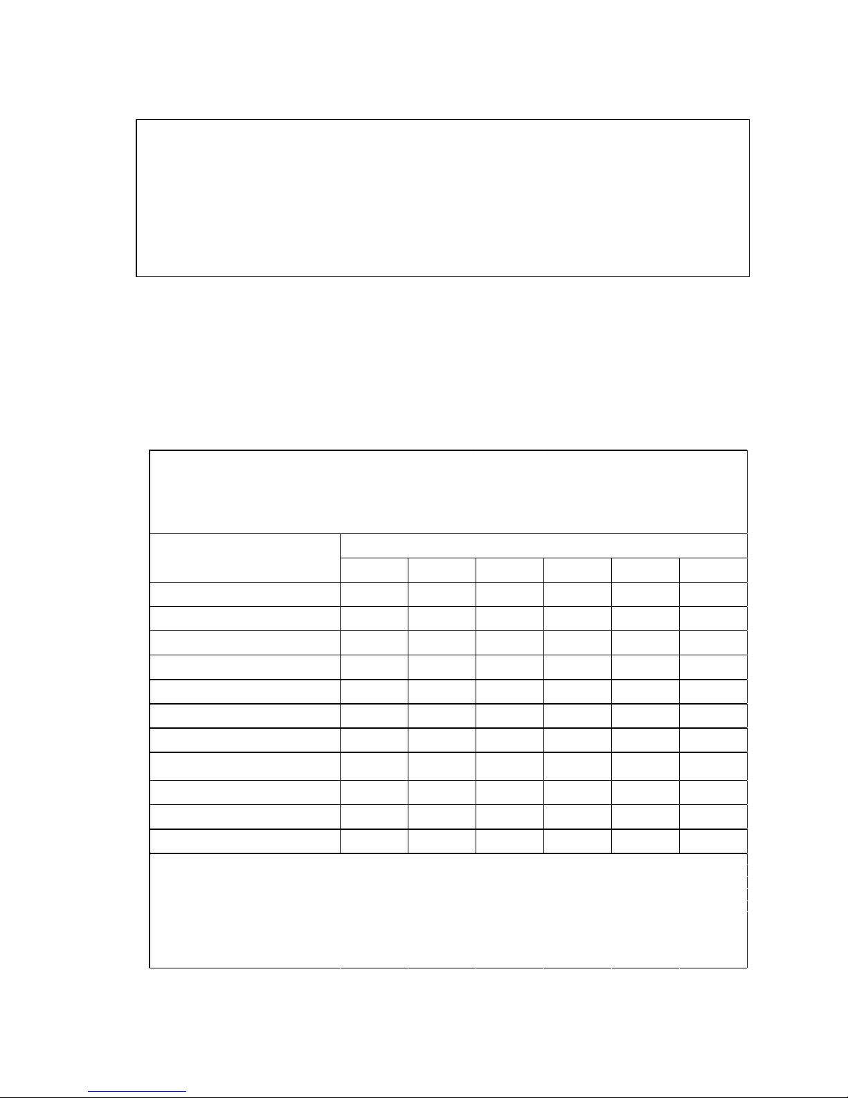
Using DGX-2 System in KVM Mode
Pb Hg
Cd Cr(VI)
PBB
PBDE
筐体 除外項目
0 0 0
0 0
プリント基板 除外項目 0
0 0 0 0
プロセッサー
除外項目 0 0 0 0 0
マザーボード 除外項目
0 0 0
0 0
電源 除外項目
0 0
0 0 0
システムメモリ 除外項目
0 0 0
0 0
ハードディスクドライブ 除外項目 0
0 0 0 0
機械部品 (
ファン、ヒートシンク、ベゼル..)
除外項目 0 0 0 0 0
ケーブル/コネクター
除外項目 0 0 0 0 0
はんだ付け材料 0 0 0
0 0 0
フラックス、クリームはんだ、ラベル、そ
の他消耗品
0 0 0 0 0 0
日本工業規格
JIS C
0950:2008により、
2006年7月1日以降に販売される特定分野の電気および電子機器について、製造者による含有物質の表示が義務付けられま
す。
機器名称:DGX-2
注:
1.
「0」は、特定化学物質の含有率が日本工業規格JIS C 0950:2008に記載されている含有率基準値より低いことを示します。
2.「除外項目」は、特定化学物質が含有マークの除外項目に該当するため、特定化学物質について、日本工業規格JIS C
0950:2008に基づく含有マークの表示が不要であることを示します。
3.「0.1wt%超」または「0.01wt%超」は、特定化学物質の含有率が日本工業規格JIS C 0950:2008 に記載されている含有率基準値を超え
ていることを示します。
主な分類
特定化学物質記号
2008年、日本における製品含有表示方法、JISC0950が公示されました。製造事業者は
、2006年7月1日
以降に販売される電気・電子機器の特定
化学物質の含有に付きまして情報提供を義務付けられました。製品の部材表示に付き
ましては、
A Japanese regulatory requirement, defined by specification JIS C 0950, 2008, mandates that
manufacturers provide Material Content Declarations for certain categories of electronic products
offered for sale after July 1, 2006.
To view the JIS C 0950 material declaration for this product, visit www.nvidia.com
Japan RoHS Material Content Declaration
DGX-2 System User Guide
100
 Loading...