

Page 1
1
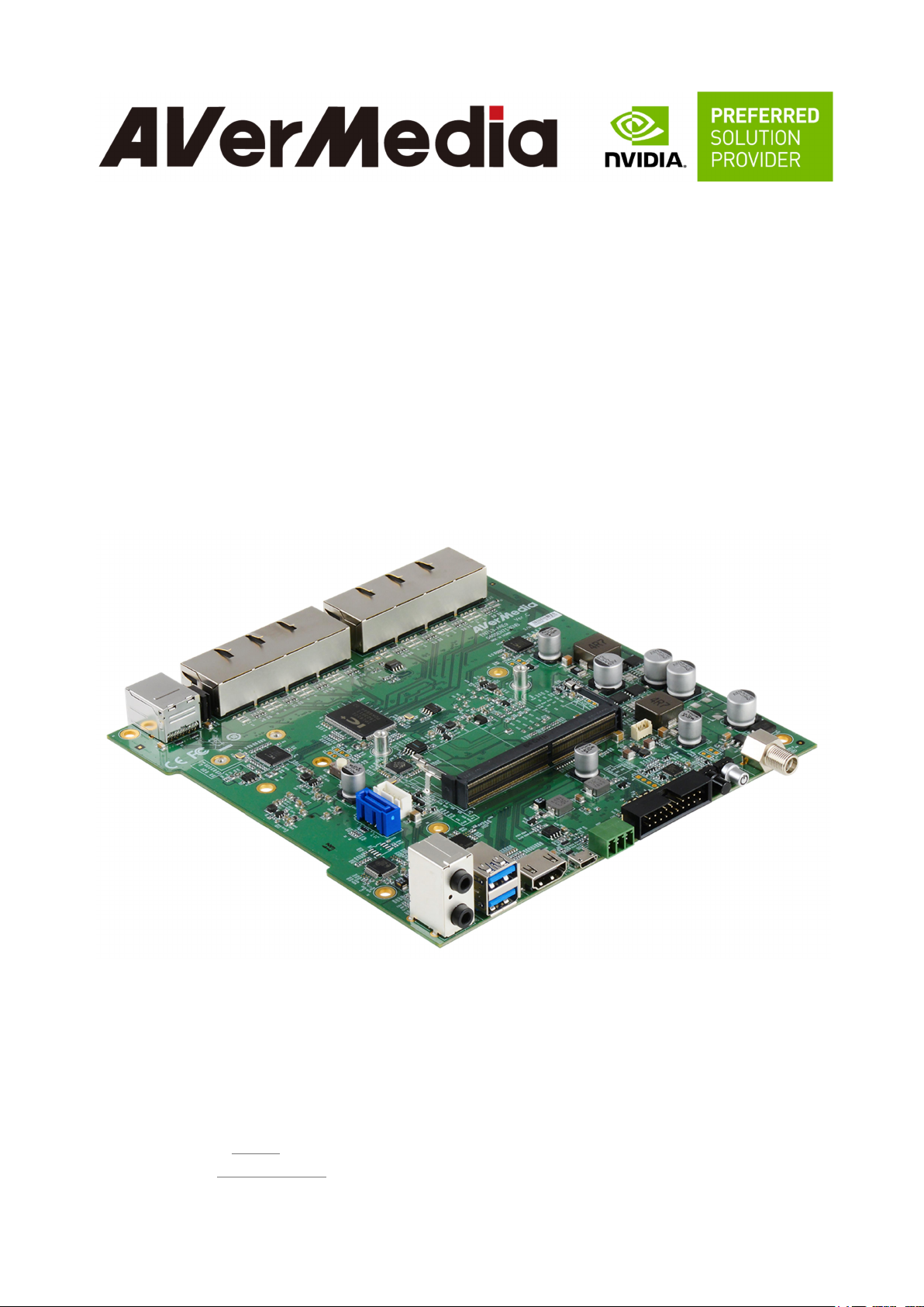
AVerAI for AI at the Edge
AVerAI Carrier Board and Box PC EN713-AAE9
Designed for NVIDIA® Jetson NanoTM Module
AVerMedia Technologies, Inc.
No. 135, Jian 1st Rd., Zhonghe Dist., New Taipei City 23585, Taiwan
Tel: 886-2-2226-3630
Fax: 886-2-3234-4842
Sales and Marketing: Contact
Technical Support: Professional User
Page 2

2
Table of Contents
Page 3

3
Preface
Disclaimer
The information contained in this user manual, including but not limited to any product
specification, is subject to change without notice. AVerMedia assumes no liability for
any damages incurred directly or indirectly from any technical or typographical errors or
omissions contained herein or for discrepancies between the product and the user manual.
Technical Support
If you experience the difficulty after reading this manual and/or using the product, please
contact the reseller from which you purchased the product. In most cases, the reseller can
help you with the product installation and the difficulty you encountered.
In case the reseller is not able to resolve your problem, our highly capable global technical
support team can certainly assist you. Our technical support section is available 24 hours
a day and 7 days a week through our website, with the click here. For more contact
information, you may find it in the section of AVerMedia Global Offices.
Contact Enquiry:
For more information of our products, pricing, and order placement, please fill in our inquiry
form here, we will contact you within 24 hours.
Download User Manual
Please click this link, here, to download the file of this user manual from AVerMedia website.
Revision History
Revision Date Updates
0.01 07/31/2019 Initial release.
Page 4
4
AVerMedia Global Offices
Page 5

5
Limited Product Warranty
AVerMedia provides the one-year product warranty. Should this product, in
AVerMedia's opinion, fail to be in the good working order during the warranty period,
AVerMedia will, at its option, repair or replace it at no charge, provided that the product
has not been subjected to abuse, misuse, accident, disaster, or non-AVerMedia authorized
modification or repair.
You may obtain the warranty service by delivering this product to an authorized
AVerMedia business partner or to AVerMedia along with the proof of purchase. Product
returned to AVerMedia must be pre-authorized by AVerMedia with an RMA (Return
Material Authorization) number marked on the outside of the package and sent prepaid,
insured, and packaged for the safe shipment. AVerMedia will return the product by
prepaid shipment service.
The limited product warranty is only valid over the serviceable life of the product. This
is defined as the period during which all components are available. Should the product
prove to be irreparable, AVerMedia reserves the right to substitute an equivalent product if
available or to retract the product warranty if no replacement is available.
The above product warranty is the only warranty authorized by AVerMedia. Under no
circumstances will AVerMedia be liable in any way for any damages, including any lost
profits, lost savings, or other incidental or consequential damages arising out of the use of,
or inability to use, such product.
Copyright Notice
The information contained in this document is subject to change without notice.
AVerMedia shall not be liable for errors contained herein or for incidental consequential
damages in connection with the furnishing, performance, or use of this material. This
document contains proprietary information that is protected by copyright. All rights are
reserved. No part of this document may be photocopied, reproduced, or translated to
another language without the prior written consent by AVerMedia.
Page 6

6
Trademark Acknowledgement
AVerMedia acknowledges all the trademarks, registered trademarks, and/or copyrights
referred to in this document as the property of their respective owners. Not listing all
possible trademarks or copyright acknowledgments does not constitute the lack of
acknowledgment to the rightful owners of the trademarks and copyrights mentioned in this
document.
ESD Warning
Electronic components and circuits are sensitive to Electrostatic Discharge (ESD). When
handling any circuit board assemblies including AVerMedia AVerAI products, it is highly
recommended that ESD safety precautions can be observed. ESD safe best practices can
include, but are not limited to the following ones.
1. Leave the circuit board in the antistatic package until it is ready to be installed.
2. Use a grounded wrist strap when handling the circuit board. At a minimum, you
need to touch a grounded metal object to dissipate any static charge, which may be
present on you.
3. Avoid handling the circuit board in the carpeted areas.
4. Handle the board by the edges and avoid the contact with the components.
5. Only handle the circuit boards in ESD safe areas, which may include ESD floor and/or
table mats, wrist strap stations, and ESD safe lab coats.
Page 7
7
1.0 Introduction
45 PSE, Power Sourcing Equipment,
AVerMedia AVerAI EN713-AAE9 is a fully featured carrier board developed for NVIDIA®
Jetson NanoTM module. It is specifically designed to have eight 10/100Mb Ethernet ports with
PoE (PSE, Power Sourcing Equipment) support.
Operating with NVIDIA® Jetson NanoTM module, EN713-AAE9 can process eight channels of
1080p30 video stream, which makes it the perfect choice in building the high performance AI
edge computing platform for the intelligent video analytics applications.
EN713-AAE9 has a footprint of 170mm (W) x 170mm (L) x 4.5mm (H), which can fit in
the compact platform for the commercial and industrial application. And it can
operate in the temperature range from -10°C up to 70°C. AVerAI EN713-AA00 provides not
only the access to a great list of latest interfaces on NanoTM module but also 1x RS-485 interface,
1x micro controller unit (MCU), and 1x RTC battery as the function enrichment.
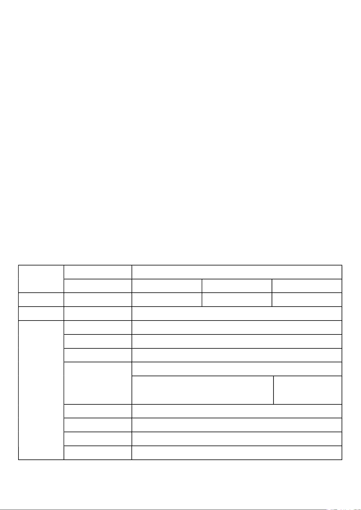
1.1 Product Specifications
Major-Name EN713-AAE9
Product Name
Sub-Name -1LC1-A00 -1FC1-A00 -1000-A00
Product Type
Core
Front I/O
Fanless/Fan/Carrier Board
System on Module (SoM)
HDMI 2.0 Output 1x HDMI 2.0a/b Type-A supports maximum resolution 3840x2160 at 60Hz
USB 2.0 1x USB 2.0 Micro-B for recovery
USB 3.0 2x USB 3.0 Type-A
10/100/1000 BASE-T
Ethernet
Fanless Box PC Fan Box PC Carrier Board
Fully support NVIDIA® Jetson Nano™
1x GbE RJ-45
Models with 1/2/4/8 PoE ports support
(8x 10/100 MbE RJ-
IEEE 802.3 AT/AF with power budget)
Model with Single
Ethernet port and no PoE
Support
Micro SD N/A
SATA Rev. 3.1 1x
Audio 1x Mic-in, 1x Speaker-out
CAN bus N/A
Page 8

8
Back I/O
RS-485 1x RS-485 Euroblock (3 pins)
Expansion Header 40 pins (2x 20 Header) with 1x 3.3V UART2, 2x SPI, 1x I2S, 2x I2C
Power Button 1x with a Green color LED
Recovery Button X 1
IEEE 802.11a/b/g/n/ac dual-band 2x2 MIMO (Optional, by using Wi-Fi
Wi-Fi
Mini-PCIe card over USB 2.0 interface)
Antenna 2x SMA female connector (Optional)
Internal PCIe
Sockets
MCU
Power
Environment
Physical
Mini-PCIe
MCU Power Function Automatically turn on system when the power input is connected
Watch Dog RTC battery life monitor
Power Input
-10°C ~ 70°C with no air
Operating Temperature
Storage Temperature -20°C ~ 85°C
Relative Humidity 40 °C @ 95%, Non-Condensing
Chassis Dimension
flow by using compact
fanless chassis with
AVerCooler™ Wave-Fin
W:212mm x L:196mm x
H:60mm (W:226 mm with
mounting ears)
Alternative option: 1x Mini-PCIe slot , Only support USB 2.0
(for Wi-Fi/BT card)
54V/2.78A for PoE (PSE, IEEE 802.3 AT/AF with power budget)
-10°C ~ 70°C with no air
flow by using compact fan
chassis with AVerCooler™
fan module
W:212mm x L:196mm x
H:60mm (W:226 mm with
mounting ears)
(Optional) -10°C ~ 70°C
with no air flow by using
AVerCooler™ fan module
W:170mm x L:170mm x
H:4.5mm
Characteristics
System
Weight 3.8 Kg 1.25 Kg 269g
Thermal Solution With fanless chassis Chassis with fan module (Optional) with fan module
Mounting Desk/Wall/Din Rail Desk/Wall/Din Rail N/A
Linux for Tegra (L4T)
Operating System
File system: Ubuntu 16.04, kernel version 4.9
System on Module (SoM)
SoM Power Consumption
Temperature Range -25°C ~ 80°C
Memory 4GB 4ch x 16-bit LPDDR4 | 1600MHz
GPU Maxwell 128-core
FLOPS (fp16) 512 GFLOPS
Fully support NVIDIA® Jetson Nano™
5W ~ 25W
Page 9
9
CPU Complex ARM® Cortex® A57 MPCore (Quad-Core) Processor with NEON Technology.
Maximum Operating
1.43GHz
Frequency
Storage 16GB e.MMC v5.1
Maximum throughput: 2160p30 (H.265) | 2160p30 (H.264) | 2160p30 (WEBM
Video Encode
VP8)
Maximum throughput: 2160p60 (H.265) | 2160p60 (H.264) | 2160p60 (WEBM
Video Decode
VP9)
EMC (TBD) CE/FCC Class B, CCC, BSMI, VCCI
Regulation
Safety (TBD) CB, UL, CCC, BSMI
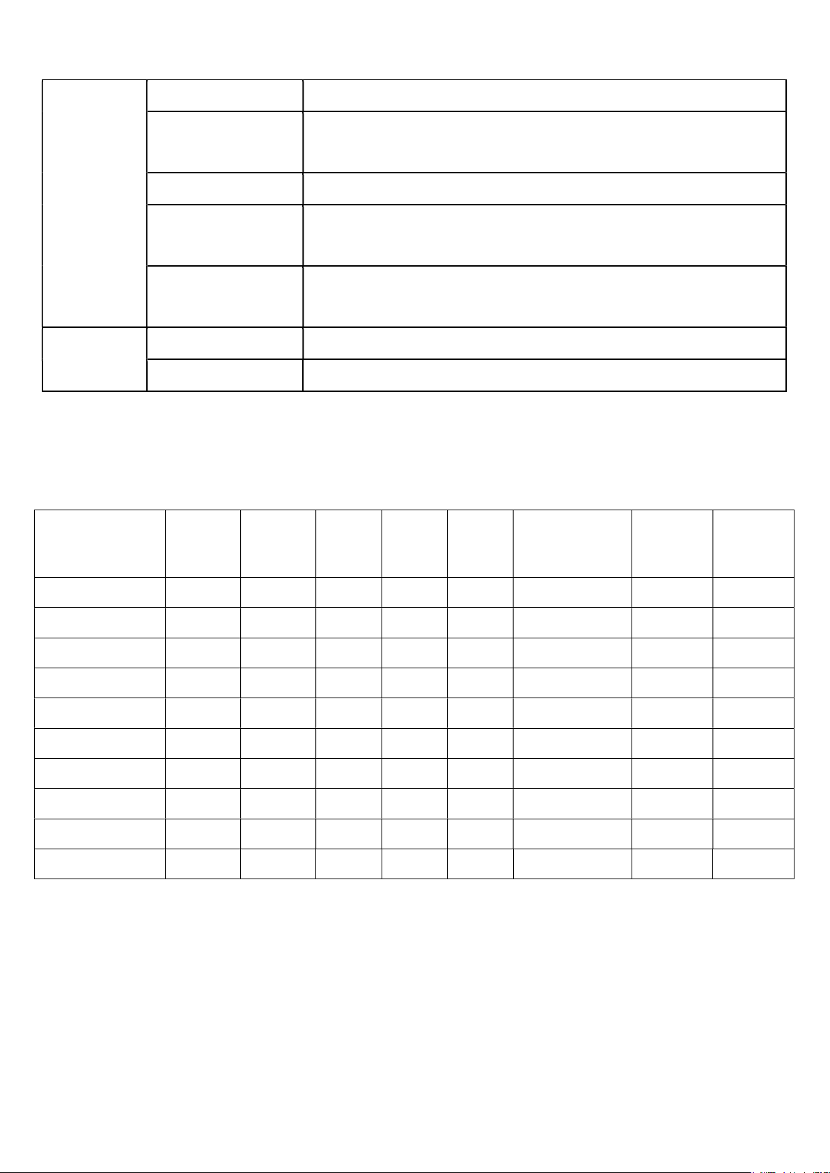
1.2 Part Numbers and Ordering Information
SKU
Part Number
EN713-AAE9 N/A N/A N/A N/A N/A N/A N/A N/A
NanoTM
Module
Active Fan
Module
and Cable
HDD
HDD
Cable
SSD
LTE Module
(internal signal
cable and antenna
included)
Power
Adapter
Power
Cord
EN713-AAE9 Installed N/A N/A N/A N/A N/A N/A N/A
EN713-AAE9 Installed Installed N/A N/A N/A N/A N/A N/A
EN713-AAE9 Installed Installed Installed Installed
N/A N/A N/A N/A N/A N/A Universal N/A
N/A N/A N/A N/A N/A N/A N/A US version
N/A N/A N/A N/A N/A N/A N/A UK version
N/A N/A N/A N/A N/A N/A N/A EU version
N/A N/A N/A N/A N/A N/A N/A JP version
N/A N/A N/A N/A N/A N/A N/A CN version
N/A N/A N/A N/A
Page 10

10
2.0 Product Overview
2.1 Block Diagram
The block diagrams are to be updated.
Page 11

11
2.2 Top View of Carrier Board
Page 12

12
2.2 Bottom View of Carrier Board
Page 13

13
2.3 Connector Summary
Designation
Description
J1 RJ45 10/100Mb 4-port Ethernet connector with POE support
J2 RJ45 10/100Mb 4-port Ethernet connector with POE support
J3 RJ45 1Gb single-port Ethernet connector
J5 260-pin SODIMM connector for NVIDIA® Jetson NanoTM module
J6 SATA power wafer
J7 Fan wafer
J8 Mic and speaker connector
J9 USB 3.1 Gen 1 2-port connector with 900mA x2
J10 HDMI video output connector
J11 USB/OTG micro-type connector
J12 RS-485 connector
J13 54VDC power Jack
J14 20-pin header UART console for debug, I2C, GPIO
J16 Mini card for USB only
J17 SATA connector
BT1 RTC battery connector
2.4 Switch Summary
Designation
Description
SW8 Force recovery button
SW9 Power on button
SW10 4-pin DIP switch with four sets of setting as defined in Section 3.20.
Page 14

14
3.0 Feature Description
3.1 Connector and Switch Locations
Page 15

15
3.2 10/100Mb 4-port Ethernet Connectors
10/100Mb 4-port Ethernet
Function
connectors, used to connect IP
cameras and/or the network
switches.
Location
J1 and J2
Type Description
Manufacturer and
Part Number
Mating Connector
Pinout
Remarks
4-pin (12-36) RJ45 with integrated
magnetics for PoE application
CHAMPWAY, CWJ46614AENL
Any standard 10/100Mb Ethernet
mating connector can be applicable.
Comply with Ethernet standards.
POE support is enabled on J1 and J2.
3.3 1Gb single-port Ethernet Connector
Function
Location
Type Description
Manufacturer and
Part Number
Mating Connector
1Gb single-port Ethernet connector,
used to connect to the host system.
J3
8-pin RJ45 with integrated
magnetics
FOXCONN,
JFM38013-0L03-4F-BX3
Any standard 1Gb Ethernet mating
connector can be applicable.
Pinout
Remarks
Comply with Ethernet standards.
None
Page 16
16
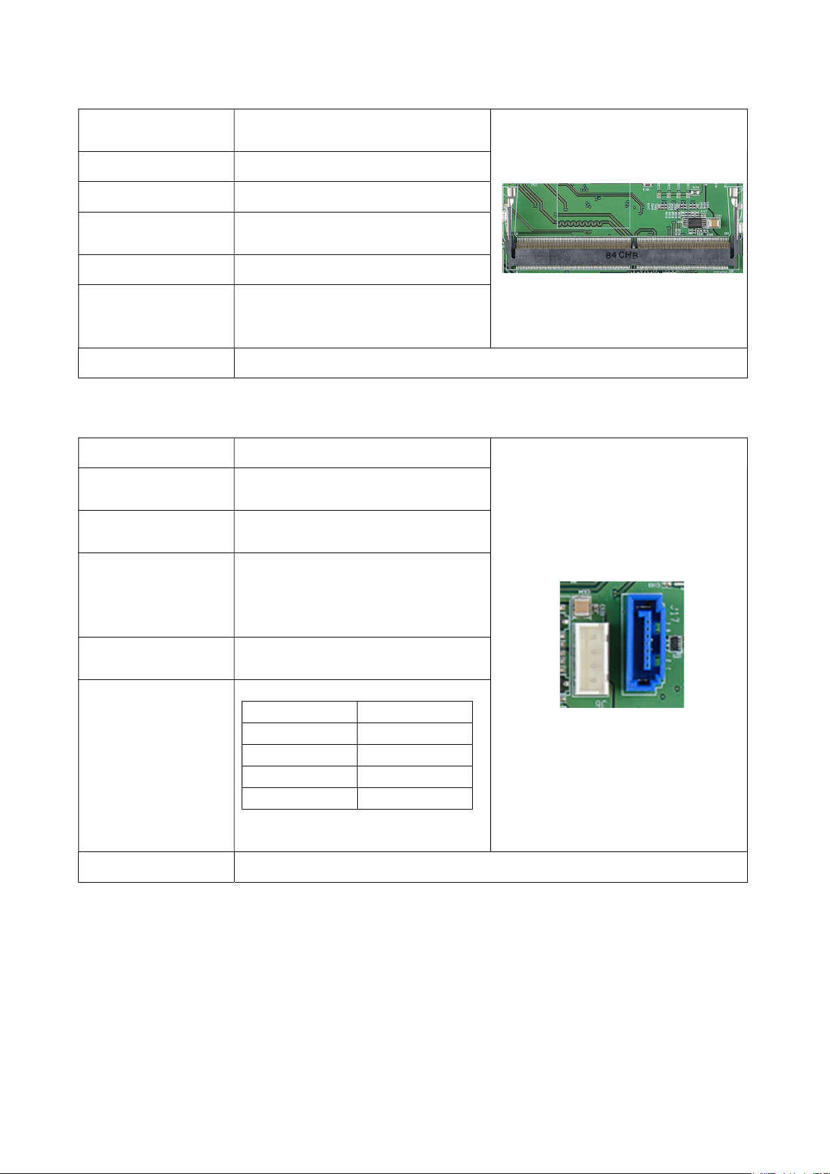
3.4 260-Pin SODIMM Connector
Function
Location
Type Description
Manufacturer and
Part Number
Mating Connector
Used to mount with and connect to
NVIDIA® Jetson NanoTM module.
J5
260-pin SODIMM connector
FOXCONN, ASAA826-EASB0-7H
SODDR4 9.2 standard
Please refer to NVIDIA Jetson
Pinout
Nano System-on-Module datasheet
for the pinout details.
Remarks
None
3.5 SATA Power Wafer and SATA Connector
Function
Location
Type Description
3.5mm surveillance hard drive
J6 (on the left) and J17 (on the
right)
SATA HD power (on the left) and
signal (on the right) connector
J6:
Manufacturer and
Part Number
PINREX, 753-81-04TW00
J7:
FOXCONN, LE18077-Z54B-4H
Mating Connector
4-pin wafer and SATA 3.0
connector
J6:
Pin Number Description
1 5V Power
Pinout
2 GND
3 GND
4 12V Power
J7: Please refer to SATA 3.0
standard
Remarks
None
Page 17
17
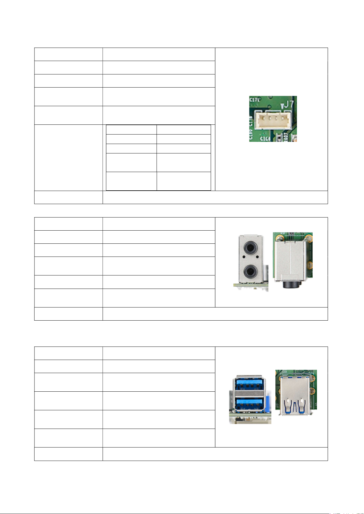
3.6 Fan Wafer
Function
Location
Type Description
Manufacturer and
Part Number
Mating Connector
Fan power and control wafer
J7
1*4 pin wafer with 1.25 mm pitch
Joint Tech,
A1250WV-04PNLNT1N00B
(Combination with PINREX’s
housing)
Pin Number Description
1 GND
2 5V Power
Pinout
3
4
Remarks
None
3.7 Mic and Speaker Connector
Function
Mic and speaker jack
TACH from fan
to module
PWM from
module to fan
Location
Type Description
Manufacturer and
Part Number
Mating Connector
Pinout
Remarks
J8
3.5 mm miniature jack
JKCR, PJD-035-87HAB
2 or 3 conductors type plug
Mic input (on the top) and speaker
output (on the bottom)
None
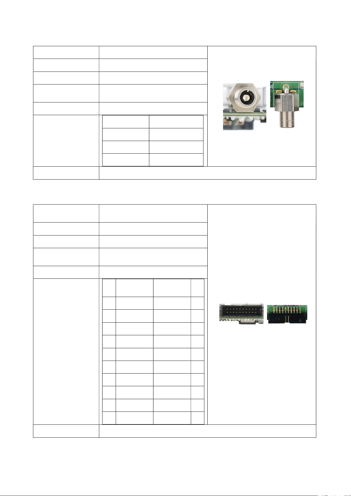
3.8 USB 3.1 Gen 1 2-Port Connector
Function
Location
Type Description
Manufacturer and
Part Number
Mating Connector
Pinout
USB 3.1 Gen 1 device connector
J9
2-port USB Type-A female
connector
CHAMPWAY,
CU3B-AFR15U-096H
Any USB standard Type-A interface
cable or device.
Please refer to USB 3.1 Gen 1
standard.
Remarks
Support 900mA x2
Page 18

18
3.9 HDMI Video Output Connector
Function
Location
Type Description
Manufacturer and
Part Number
Mating Connector
Pinout
Remarks
HDMI Type-A TX connector
J10
HDMI Type-A female connector
Compupack, ACNHM220028-001
Any HDMI standard Type-A
interface cable or device.
Please refer to HDMI standard.
None
3.10 USB/OTG Micro-Type Connector
Function
Location
Type Description
Manufacturer and
Part Number
Mating Connector
Pinout
OTG programming recovery
J11
USB Micro-type female connector
Fullglory, FG-MCB-111440
Any USB standard Micro-type
interface cable or device.
Please refer to USB Micro-type
standard.
Remarks
None
3.11 RS-485 Connector
Function
Location
Type Description
Manufacturer and
Part Number
Mating Connector
RS485 interface from Jetson Nano
module UART control
J12
3-pin terminal block
DECA, ME030-38103T
Combination with the plug terminal
block from DECA
Pinout
Remarks
Pin Number Description
1 GND
2 B
3 A
Page 19
19
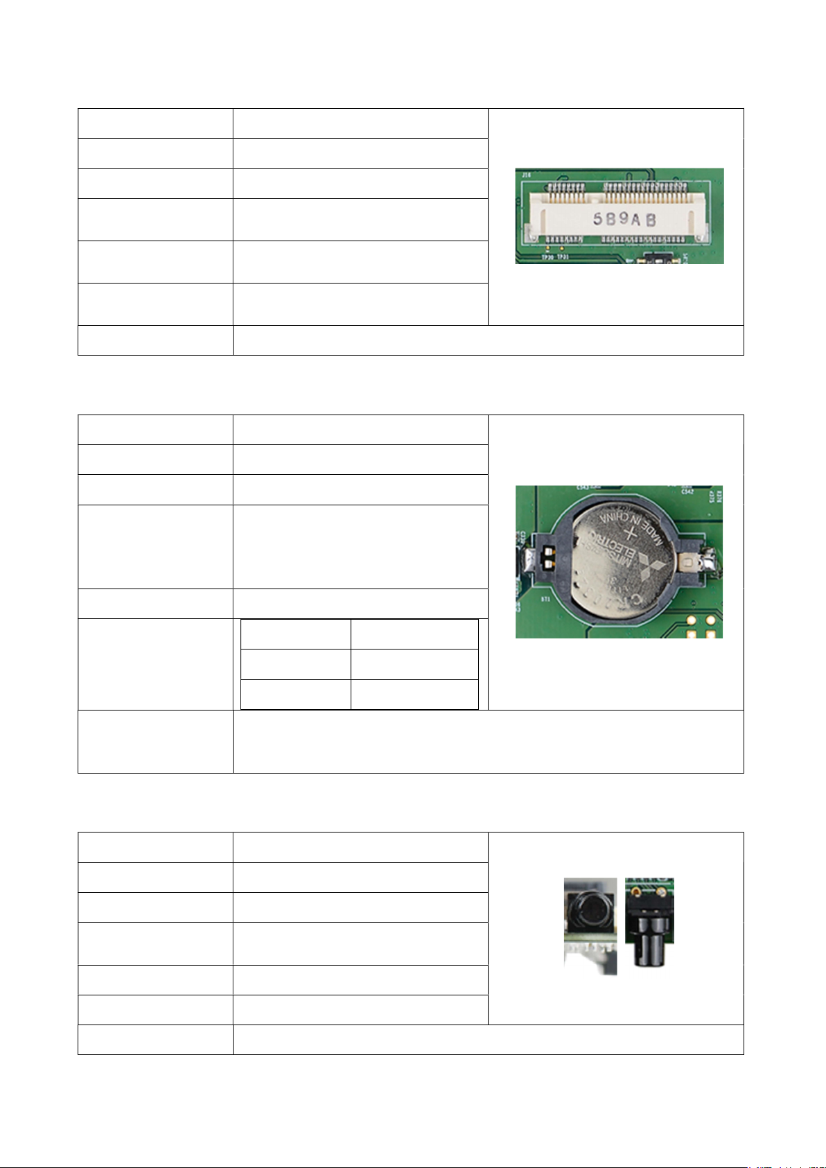
3.12 54VDC Power Jack
1
3
5
9
13
15
17
19
Function
Location
Type Description
Manufacturer and
Part Number
54V DC power input
J13
2.5 mm power jack
JKCR, DCD-020-105B
Mating Connector Any 2.5mm power plug cable
Pin Number Description
3 GND
Pinout
1 54V Power
2 GND
Remarks
None
3.13 20-Pin Header
Function
UART console for debug, I2C,
GPIO
Location
Type Description
Manufacturer and
Part Number
Mating Connector
Pinout
J14
2.54 mm pitch 2*10 header
COXOC, 302AE20PGAR003
Any 2.5mm pitch DuPont wire
Pin
Description Description
#
3V Power 5V Power 2
GND GND 4
I2C1_SDA UART2_TXD 6
7 I2C1_SCL UART2_RXD 8
I2C0_SDA GND 10
11 I2C0_SCL GPIO 12
GPIO GPIO 14
GPIO GPIO 16
Pin
#
Remarks
GPIO GPIO 18
GPIO GPIO 20
None
Page 20
20
3.14 Mini Card Connector
Function
Location
Type Description
Manufacturer and
Part Number
Mating Connector
Pinout
Remarks
LTE or Wi-Fi Module
J16
Mini-Card for USB
FOXCONN, AS0B221-S68Q-7H
Any Mini-Card standard interface
device.
Please refer to Mini-Card standard
for the pinout details.
Support USB 2.0 only, not PCIe
3.15 RTC Battery Connector
Function
Location
Type Description
RTC battery for module
BT1
RTC holder and RTC battery
Holder:
Manufacturer and
Part Number
LOTES, AAA-BAT-054-P06
RTC Battery:
MITSUBISHI, CR2032 3V
Mating Connector Any CR2032 3V battery
Pin Number Description
Pinout
1 3V Power
2 GND
Please be reminded to pay the proper attention on the polarity of this 3V
Remarks
battery, when it is being replaced. The correct placement is to keep the
“+” mark on the battery outward, as shown in the above photo.
3.16 Force Recovery Button
Function
Location
Type Description
Manufacturer and
Part Number
Force recovery
SW8
Button
N/A
Mating Connector N/A
Pinout
Remarks
N/A
None
Page 21
21
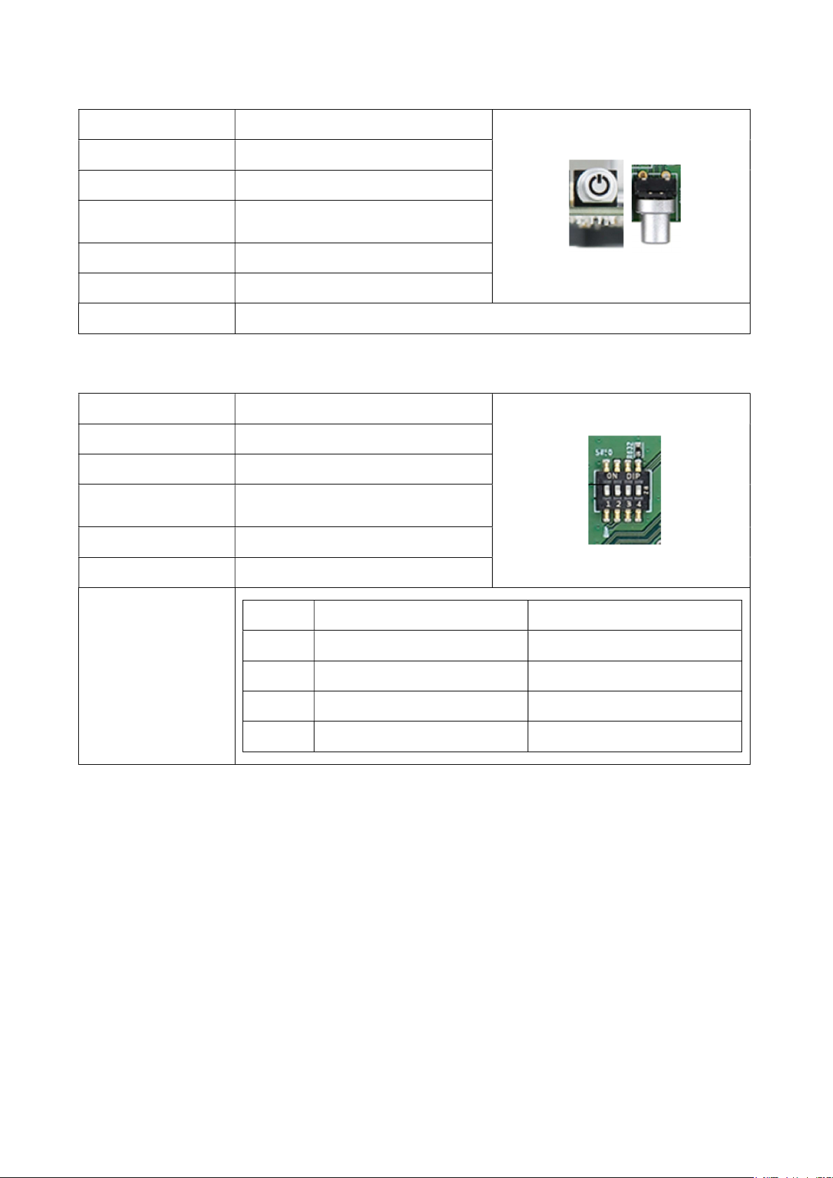
3.17 Power on Button
Function
Location
Type Description
Manufacturer and
Part Number
Power control button
SW9
Button with Green LED
N/A
Mating Connector N/A
Pinout
Remarks
N/A
The green light on LED is activated when the board is powered on.
3.18 4-Pin DIP Switch
Function Optional function selection
Location
Type Description
Manufacturer and
Part Number
Mating Connector
SW10
4 SPST DIP switch
N/A
N/A
Pinout
Please refer to the following table.
SW10 Default (OFF) ON
Remarks
S1 Fan PWM controller Fan always on
S2 Auto power on Auto power on disabled
S3 RS-485 normal mode RS-485 terminal mode
S4 Test mode off
Test mode on (for the factory use)
3.19 Other Switch and Jumpers
Other switch and jumpers, such as SW1, JP3, JP4, and JP5, etc. marked on the printed circuit
board of EN713-AAE9 carrier board, are reserved for the internal use by AVerMedia. They are
not open to the client application.
Page 22

22
4.0 Installation
1. Check and ensure all the external system power supplies are turned off.
2. Install NVIDIA
and be sure to follow the manufacturer’s instructions for the proper installation of the
mounting hardware, heat sink or heat spreader, fan, and any other applicable
requirements from the associated manufacturers.
3. Install the necessary cables for the application. The cables can include the following
ones. For the additional information of these mentioned cables, please refer to 8.0
Cable Assembly in this manual.
Power cable to the input power connector (J13) on the carrier board.
®
Jetson NanoTM module onto 260-pin SODIMM connector (J5). Check
HDMI video display cable to HDMI video output connector (J10).
Mouse and keyboard cables to USB connectors (J9).
4. Connect the power cable to the power adapter.
5. Turn on the power adapter. (Please be reminded NOT to power on the system by
plugging in the live power.)
5.0 Software
For L4T (Linux for Tegra) BSP and the software support associated with NVIDIA® Jetson
NanoTM module, please check this link, https://www.avermedia.com/professional/download/en713_aae9#ans_part, to
download the file from AVerMedia website.
6.0 Force Recovery Mode
USB 3.l/OTG port (J11) of EN713-AAE9 can be used to re-program NVIDIA
NanoTM module by using the other host system running NVIDIA Jetpack
TM
, as the procedure
®
Jetson
Page 23

23
described below.
1. Power off the system. Ensure the system power must be completely OFF, instead of
staying in the suspend mode or the sleep mode.
2. Connect a USB cable from OTG USB port to the other host system which will be used
to re-program the new system file into NVIDIA
3. Press and hold down Force Recovery Button (SW8) and then power on the carrier
®
Jetson NanoTM module.
board.
4. After three seconds, release Force Recovery Button.
5. NVIDIA® Jetson NanoTM module will show up on the USB list of the host system as a
new NVIDIA target device.
6. After the system software is updated successfully, please ensure to power off the
system. A clean power-on will then revert OTG port back to the host mode.
7.0 Power Consumption
110W
 Loading...