

Page 1

nForce 680i SLI/
nForce 680i LT SLI
Copyright
All rights are reserved. No part of this publication may be reproduced, transmitted, transcribed,
stored in a retrieval system or translated into any language or computer language, in any form
or by any means, electronic, mechanical, magnetic, optical, chemical, manual or otherwise,
without the prior written permission of the company. Brands and product names are
trademarks or registered trademarks of their respective companies.
The vendor makes no representations or warranties with respect to the contents herein and
especially disclaim any implied warranties of merchantability or fitness for any purpose.
Further the vendor reserves the right to revise this publication and to make changes to the
contents herein without obligation to notify any party beforehand. Duplication of this
publication, in part or in whole, is not allowed without first obtaining the vendor’s approval in
writing.
Trademark
All the trademarks or brands in this document are registered by their respective owner.
Disclaimer
We make no warranty of any kind with regard to the content of this user’s manual. The content
is subject to change without notice and we will not be responsible for any mistakes found in
this user’s manual. All the brand and product names are trademarks of their respective
companies.
FCC Compliance Statement
This equipment has been tested and found to comply with the limits of a Class B digital device,
pursuant to Part 15 of the FCC Rules. These limits are designed to provide reasonable
protection against harmful interference in a residential installation. This equipment generates,
uses and can radiate radio frequency energy and, if not installed and used in accordance with
the instructions, may cause harmful interference to radio communications. Operation of this
equipment in a residential area is likely to cause harmful interference in which case the user
will be required to correct the interference at his own expense. However, there is no guarantee
that interference will not occur in a particular installation.
CE Mark
The device is in accordance with 89/336 ECC-ENC Directive.
Ver: EG101
Page 2

Mainboard nForce 680i SLI/
Mainboard nForce 680i LT SLI
nForce 680i SLI/
nForce 680i LT SLI
Intel
®
Core
nVIDIA® nForce 680i SLI MCPs/
nForce 680i LT SLI MCPs
Support Socket 775
TM
2 Extreme/ Core
Pentium
Pentium
User Manual
Dimensions (ATX form-factor):
244mm x 305mm ( W x L )
Operating System:
Windows® Vista/ Windows® XP
TM
®
Extreme Edition/
®
2 Quad/ Core
Processors
TM
2 Duo/
Page 3
Mainboard nForce 680i SLI/
Mainboard nForce 680i LT SLI
Things You Have To Know
The images and pictures in this manual are for reference only and may vary
from the product you received depending on specific hardware models, third
party components and software versions.
This mainboard contains very delicate IC chips. Always use a grounded
wrist strap when working with the system.
Do not touch any IC chip, lead, connector or other components.
Always unplug the AC power when you install or remove any device on the
mainboard or when confuguring pins and switches.
Packing List
nForce 680i SLI/ nForce 680i LT SLI Mainboard
I/O Shield
IDE Cable
SATA Cable
SLI Bridge
1394 Cable (Optional)
Cooling Fan (nForce 680i SLI only)
Mainboard Driver & User Manual CD
Mainboard Quick Installation Guide
Symbols
Attention- Important Information
Follow the procedures below…
Troubleshooting Tips
Refer to other sections in this manual…
Page 4

Mainboard nForce 680i SLI/
Mainboard nForce 680i LT SLI
Table of Contents
CHAPTER 1. GETTING STARTED ....................................................1
INTRODUCTION.......................................................................................................1
SPECIFICATION .......................................................................................................2
CONFIGURATION .................................................................................................... 5
Layout of nForce 680i SLI .............................................................................. 5
Layout of nForce 680i LT SLI......................................................................... 6
HARDWARE INSTALLATION ................................................................................... 7
CPU Processor Installation.............................................................................. 7
Memory Installation: DIMM0/1/2/3................................................................8
Back Panel Configuration.............................................................................. 10
Connectors.....................................................................................................13
Front Panel Headers: FRONTPNL................................................................14
EZ Control Button .........................................................................................15
Headers & Jumpers........................................................................................15
Audio Configuration...................................................................................... 17
Slots ............................................................................................................... 17
Power Supply Attachments............................................................................ 18
CHAPTER 2. BIOS SETUP ........................................................... 20
INTRODUCTION..................................................................................................... 20
MAIN MENU .........................................................................................................21
CHAPTER 3: SOFTWARE SETUP................................................... 23
SOFTWARE LIST ................................................................................................... 23
SOFTWARE INSTALLATION ................................................................................... 23
CHAPTER 4: TROUBLESHOOTING................................................. 27
APPENDIX I: 8/6/4/2 CHANNEL AUDIO EFFECT SETUP.........................................30
APPENDIX II: RAID SETUP...................................................................................32
APPENDIX III: SLI (SCALABLE LINK INTERFACE) SETUP ....................................70
Page 5

Mainboard nForce 680i SLI/
Mainboard nForce 680i LT SLI
Chapter 1. Getting Started
Introduction
Thanks for choosing nForce 680i SLI/ nForce 680i LT SLI mainboards. They are based on
®
nVIDIA
SLI/ nForce 680i LT SLI support Intel
Pentium
nForce 680i SLI/ 680i LT SLI Northbridge and Southbridge chipsets. The nForce 680i
®
1333 MHz/ 1066 MHz/ 800 MHz.
The nForce 680i SLI/ nForce 680i LT SLI provide four DIMM (Dual In-Line Memory Modules)
sockets allowing you to install 240-pin, unbuffered non-ECC, DDRII 800/ 667/ 533 SDRAMs.
They also support Dual Channel Technology and allow you installing a total memory capacity
of 8 GB.
These mainboards provide two PCI-E x16 slots which can be used with two identical
SLI-ready PCI-Express graphics cards, enabling SLI Technology and significantly increasing
graphics performance <See Appendix III>. Furthermore, the nForce 680i SLI also provides
one PCI-E x8 slot for use with a graphics card. There are two PCI-E x1 slots provided for use
with PCI-E x1 compatible expansion cards. Two standard PCI slots for use with standard PCI
expansion cards are also allowed.
The nForce 680i SLI/ nForce 680i LT SLI provide one floppy disk drive connector that can be
used with 360KB/720KB/ 1.2MB/1.44MB/2.88MB drives. There is also one IDE connector for
connecting two IDE hard drives supporting Ultra ATA 33/66/100/133. Moreover, these
mainboards come with Serial ATA II feature, six SATA II connectors which the interfaces can
provide the transmit rate up to 3 Gbps and also support RAID 0/ 1/ 0+1/ 5 JBOD mode <See
Appendix II>
The onboard High Definition Audio CODEC (ALC885) supports 8/6/4/2 channel audio play
<See Appendix I>. These mainboards also support the Sony/Philips Digital Interfaces (SPDIF)
output function.
The nForce 680i SLI also comes with two onboard 10/100/1000 Mbps Ethernet LAN chips.
There are dual LAN ports on the back panel of your case that you can directly plug into an
Internet cable. The nForce 680i LT SLI only provides one 10/100/1000 LAN port.
There are maximal ten USB2.0/ 1.1 ports which can be set up on the nForce 680i SLI
mainboard. Eight USB2.0/ 1.1 ports are available on the nForce 680i LT SLI mainboard.
All the information (including hardware installation and software installation) in this manual are
for reference only. The contents in this manual may be updated without notice. The company
will not assume any responsibility for any errors or mistakes within.
®
CoreTM 2 Extreme/ CoreTM 2 Quad/ CoreTM 2 Duo/
Extreme Edition/ Pentium® Processors with FSB (Front Side Bus) frequencies up to
1
Page 6

Specification
Mainboard nForce 680i SLI/
Mainboard nForce 680i LT SLI
CPU
Support Socket 775
Support Intel® CoreTM 2 Extreme/ CoreTM 2 Quad/ CoreTM 2 Duo/ Pentium® Extreme
Edition/ Pentium
®
Processors
Support Hyper-Threading Technology
Support 1333 MHz/ 1066 MHz/ 800 MHz/ 533 MHz FSB (Front Side Bus) Frequencies
Chipset
Northbridge Chipset – nVIDIA® nForce 680i SLI SPP/ 680i LT SLI SPP
Southbridge Chipset – nVIDIA® nForce 680i SLI MCP/ 680i LT SLI MCP
I/O Controller – Winbond® W83627DHG
High Definition Audio Codec – Realtek® ALC885
LAN Controller – Marvell® 88E1116
IEEE1394 Controller – TI® TSB43AB22A
Memory
Four DIMM sockets
Supports unbuffered & non-ECC DDRII 800/ 667/ 533 SDRAM
Supports a total memory capacity of up to 8 GB
Supports Dual Channel data bus
Onboard HD Audio CODEC (ALC885)
High performance CODEC with high S/N ratio (>100 db)
Compatible with Azalia 1.0 specification
Supports 8/6/4/2 channel playback capability
Supports jack sensing and re-tasking function
Microphone AEC, NS, and BF technology for voice application
Supports Sony/ Philips Digital Interfaces (S/PDIF) functionality
2
Page 7

Mainboard nForce 680i SLI/
Mainboard nForce 680i LT SLI
Slots
Five PCI-Express interface slots for graphics cards and expansion cards
1. Two PCI-E x16 slots: supports x16 mode for true dual-graphics SLI configurations
2. One PCI-E x8 slot: supports x8 mode for future GPU physics applications nForce
680i SLI only
3. Two PCI-E x1 slots: supports up to x1 mode with 250 MB/s one-way bandwidth
Two PCI interface slots for expansion cards
FDD Connector
Supports one FDD connector to set up to two floppy disk drives
Supports 360KB/ 720KB/ 1.2MB/ 1.44MB/ 2.88MB
IDE Connector
One IDE connector
Supports up to two IDE devices
Supports Ultra ATA 33/66/100/133
Supports high capacity hard disk drives
Serial ATA II Connectors
Six SATA II connectors
Supports SATA 2.0 specification with data transfer rate up to 3 Gbps
One SATA II connector can only support one SATA II HDD
Onboard LAN Chip
Supports Dual LAN nForce 680i SLI only
Supports 10/100/1000 Mbps Ethernet LAN
I/O facility Connectors
Supports one PS/2 mouse port and one PS/2 keyboard port
Supports one IEEE1394 port on back panel
Supports one SPDIF OUT port on back panel
Supports one serial port (COM1) header and one IEEE1394 header with external
device connected
3
Page 8

Mainboard nForce 680i SLI/
Mainboard nForce 680i LT SLI
Universal Serial Bus
Six onboard USB 2.0/ 1.1 ports nForce 680i SLI only
Two front USB headers come with this mainboard for additional four USB ports
Support a maximum of ten USB ports to connect USB compatible devices
nForce 680i SLI only
BIOS
Phoenix-Award™ BIOS
Support APM 1.2
Support ACPI 2.0 power management
Green Function
Supports ACPI (Advanced Configuration and Power Interface)
Supports Phoenix-Award™ BIOS power management function
Supports S0 (normal), S1 (power on suspend), S3 (suspend to RAM), S4 (suspend to
disk – depends on OS), and S5 (soft – off).
Shadow RAM
Integrated memory controller provides shadow RAM functionality and supports ROM
BIOS
Flash Memory
Supports flash memory functionality
Supports ESCD functionality
Hardware Monitor Function
Monitors CPU/ Northbridge/ Chassis Fan Speed
Monitors CPU temperature
Monitors CPU/ Memory/ System voltages
4
Page 9
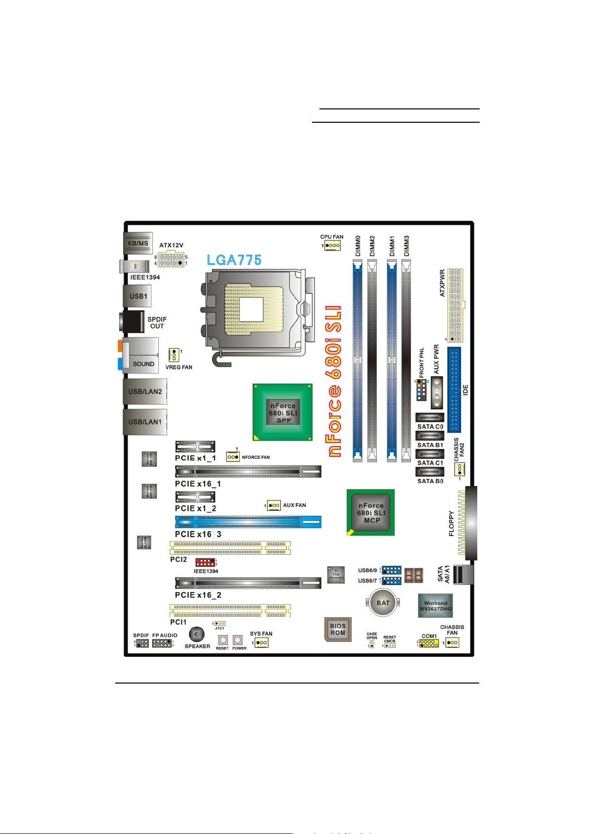
Configuration
Layout of nForce 680i SLI
Mainboard nForce 680i SLI/
Mainboard nForce 680i LT SLI
5
Page 10
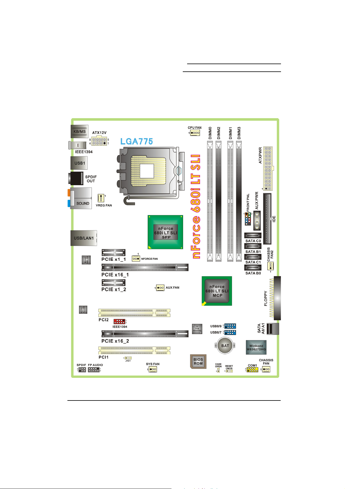
Layout of nForce 680i LT SLI
Mainboard nForce 680i SLI/
Mainboard nForce 680i LT SLI
6
Page 11
Mainboard nForce 680i SLI/
A
p
Mainboard nForce 680i LT SLI
Hardware Installation
This section will assist you in quickly installing your system hardware. Wear a wrist ground
strap before handling components. Electrostatic discharge may damage the system’s
components.
CPU Processor Installation
These mainboards support Intel® CoreTM 2 Extreme/ CoreTM 2 Quad/ CoreTM 2 Duo/ Pentium®
Extreme Edition/ Pentium
®
Processors using a Socket 775. Before building your system, we
suggest you to visit the Intel website and review the processor installation procedures.
http://www.intel.com
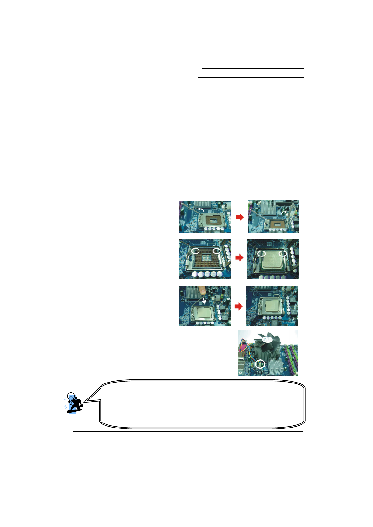
CPU Socket 775 Configuration Steps:
1. Locate the CPU socket 775 on
your mainboard and nudge the
lever away from the socket as
shown. Then lift the lever to a
140-degree angle (A). Next, lift up
the iron cover (B).
2. There are 2 distinctive marks
located near the corners of the
socket on the same side as the
lever as shown (C). Match these
marks with the marks on the CPU
and carefully lower the CPU down
onto the socket (D).
3. Replace the iron cover and then
lower the lever until it snaps back
into position (E). This will lock
down the CPU (F).
4. Smear thermal grease on the top of the CPU. Lower the
CPU fan onto the CPU/CPU socket and secure it using the
attachments or screws provided on the fan. Finally, attach
the fan power cord to the CPUFAN header.
ttention
DO NOT touch the CPU pins in case they are damaged. Also, make sure
that you have completed all installation steps before powered on the
system. Finally, double-check that the cooling fan is properly installed and
the CPU fan power cord is securely attached, in case your CPU and other
sensitive com
onents are damaged because of high temperatures.
7
Page 12
Mainboard nForce 680i SLI/
Mainboard nForce 680i LT SLI
FAN Headers: CPU FAN, NFORCE FAN
There are several fan headers available for cooling fans on the mainboard. Here describes the
two important ones only. The cooling fans play an important role in maintaining ambient
temperatures in your system. The CPUFAN header is attached with a CPU cooling fan. The
NFORCE FAN header is attached with the nForce SPP fan.
Pin Assignment
1 Control
2 Sense
1
CPU FAN
1
NFORCE FAN
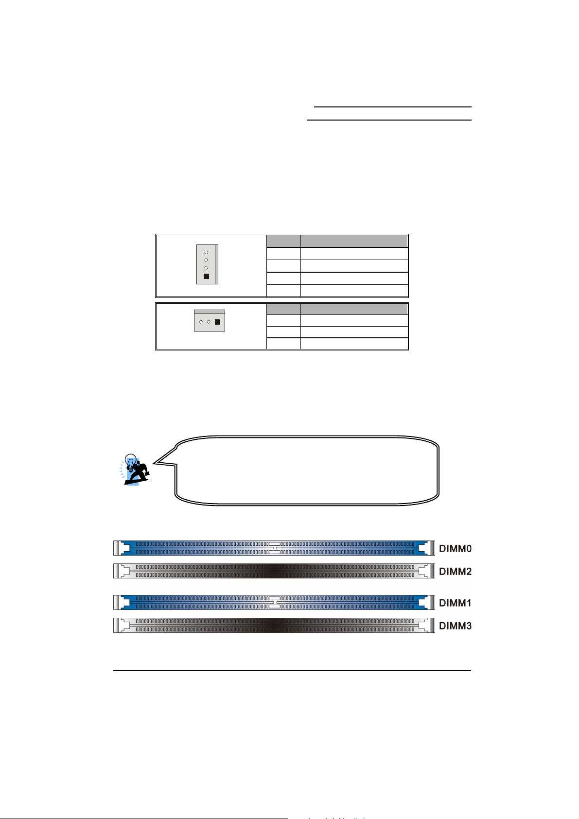
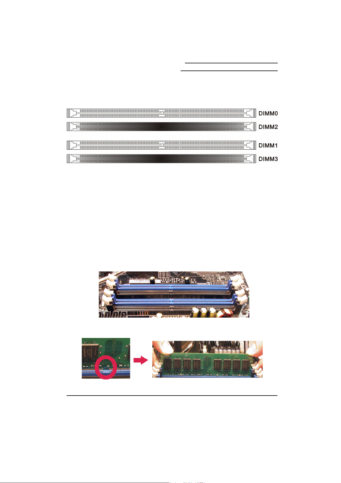
Memory Installation: DIMM0/1/2/3
The nForce 680i SLI/ nForce 680i LT SLI mainboards provide four DIMM (Dual In-Line
Memory Modules) sockets which allow you to install 240-pin, unbuffered non-ECC, DDRII 800/
667/ 533 SDRAMs. They also support Dual Channel Technology and allow you to install a
total memory capacity of 8 GB.
DIMM on the nForce 680i SLI
Attention
It is recommended that to install memories which are identical
specifications (same timing specifications and same DDR II
speed) to achieve the best effects. It may cause the failure of
power-on or lower memory speed if installing different type,
3 PWR
4
GND
Pin Assignment
1 Sense
2 +12V
3
GND
8
Page 13
DIMM on the nForce 680i LT SLI
Mainboard nForce 680i SLI/
Mainboard nForce 680i LT SLI
How to enable Dual-Channel DDRII:
1. These mainboards provide Dual-Channel functionality for the four DIMM sockets.
Enabling Dual-Channel will significantly increase your data access rate than the before.
DIMM0 and DIMM1 share one channel, and DIMM2 and DIMM3 share another channel.
2. To enable Dual-Channel, you need to install memories in different channels of DIMM
sockets. According to the definition by Intel, once one channel of the memory capacity is
the same with the other channel, the Dual-Channel will be enabled then.
For example, if you install one 256 MB memory in DIMM0 and another in DIMM1 (256MB x 2
= 512MB), you must install a total of 512 MB memory in DIMM2 or DIMM3, so that the
Dual-Channel can be enabled.
3. If you only need to install one memory, it is recommended to install it in DIMM0 or DIMM1.
Memory Installation Steps:
1. Pull the white plastic tabs at both ends of the slot away from the slot.
2. Match the notch on the RAM module with the corresponding pattern in the DIMM slot.
This will ensure that the module will be inserted with the proper orientation.
9
Page 14
Mainboard nForce 680i SLI/
Mainboard nForce 680i LT SLI
3. Lower the RAM module into the DIMM Slot and press firmly using both thumbs until the
module snaps into place.
4. Repeat steps 1, 2 & 3 for the remaining RAM modules.
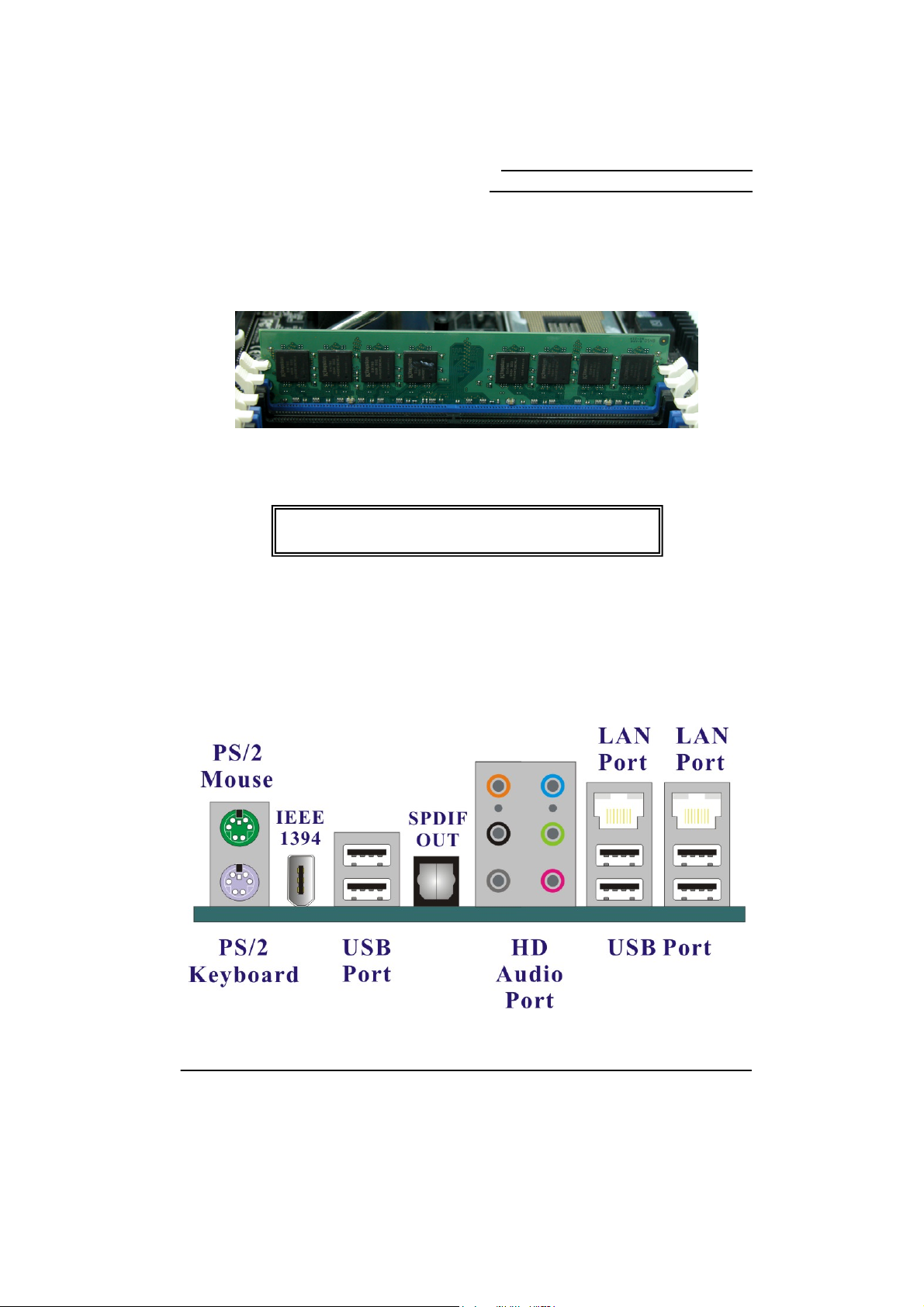
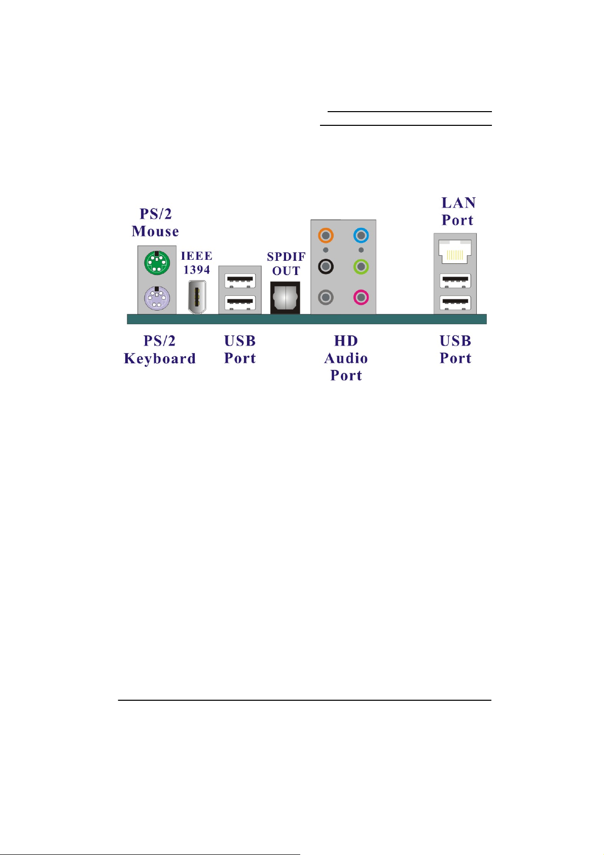
Back Panel Configuration
Back Panel of the nForce 680i SLI
The pictures above are for reference only. Your actual
installation may vary slightly from the pictures.
10
Page 15
Back Panel of the nForce 680i LT SLI
Mainboard nForce 680i SLI/
Mainboard nForce 680i LT SLI
PS/2 Mouse & PS/2 Keyboard Ports: KB/MS
These mainboards provide a standard PS/2 mouse port and a PS/2 keyboard port.
S/PDIF OUT Port: SPDIF Out
The S/PDIF output is capable of providing digital audio to external speakers or compressed
AC3 data to an external Dolby digital decoder. Use this feature only when your stereo system
has digital input function.
IEEE1394 Port: IEEE1394
There is one IEEE1394 port on the back panel of your case that allows you to attach
compatible device is also available.
USB Ports/LAN Ports: USB1, USB/LAN1, USB/LAN2
There are six onboard USB 2.0/ 1.1 ports on the back panel. These USB ports are used to
attach with USB devices, such as keyboard, mice and other USB supported devices. There
are also dual 10/100/1000 Mbps Ethernet LAN ports available for you to attach an Internet
cable. 《nForce 680i LT SLI supports four onboard USB 2.0/1.1 ports and one LAN
port.》
11
Page 16
Mainboard nForce 680i SLI/
Mainboard nForce 680i LT SLI
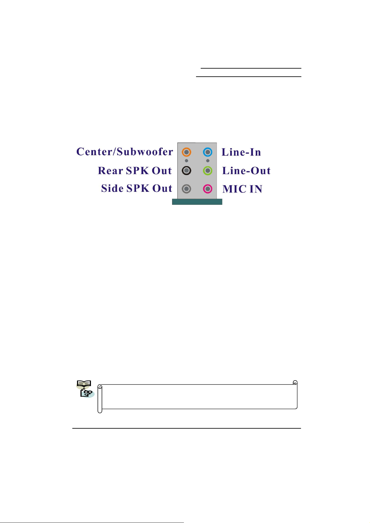
Audio Ports: SOUND
This mainboard provides six HD Audio ports for 8/6/4/2 channel playback capability. With jack
sensing, auto detecting and adjusting, the device will make it easier to Plug and Play for you.
Line-In (blue)
This port is for audio input and connects to external audio devices such as CD player, tape
player or other audio devices when the 8/6/4/2 channel audio effects driver is enabled.
Line-Out/Front Speaker-out (green)
This port is an output audio port used for connecting to speakers or a headset. A dual channel
audio system is to provide basic audio functionality. When the 8/6/4/2 channel audio system is
enabled, this port will output audio for the front speakers.
Mic-In (pink)
This port is for connecting to a microphone. When the 8/6/4/2 channel audio system is
enabled, this port will be the input of your microphone.
Center/ Subwoofer(orange)
This port connects with the center/ subwoofer speakers. It will be functional when the 8/6
channel audio system is driven for center/ subwoofer output.
Rear Speaker Out(black)
This port is only functional for the output of the surround sound rear speakers when the 8/6/4/2
channel audio driver is installed and enabled.
Side Speaker Out(gray)
This port will be effective for the output of side surround speakers when the 8 channel audio
system is set.
This mainboard supports multi-channel audio system which allows you to
transform your 2 speaker audio system into 8/ 6/ 4 speaker audio system.
See Appendix I for more information.
12
Page 17
Mainboard nForce 680i SLI/
Mainboard nForce 680i LT SLI
Connectors
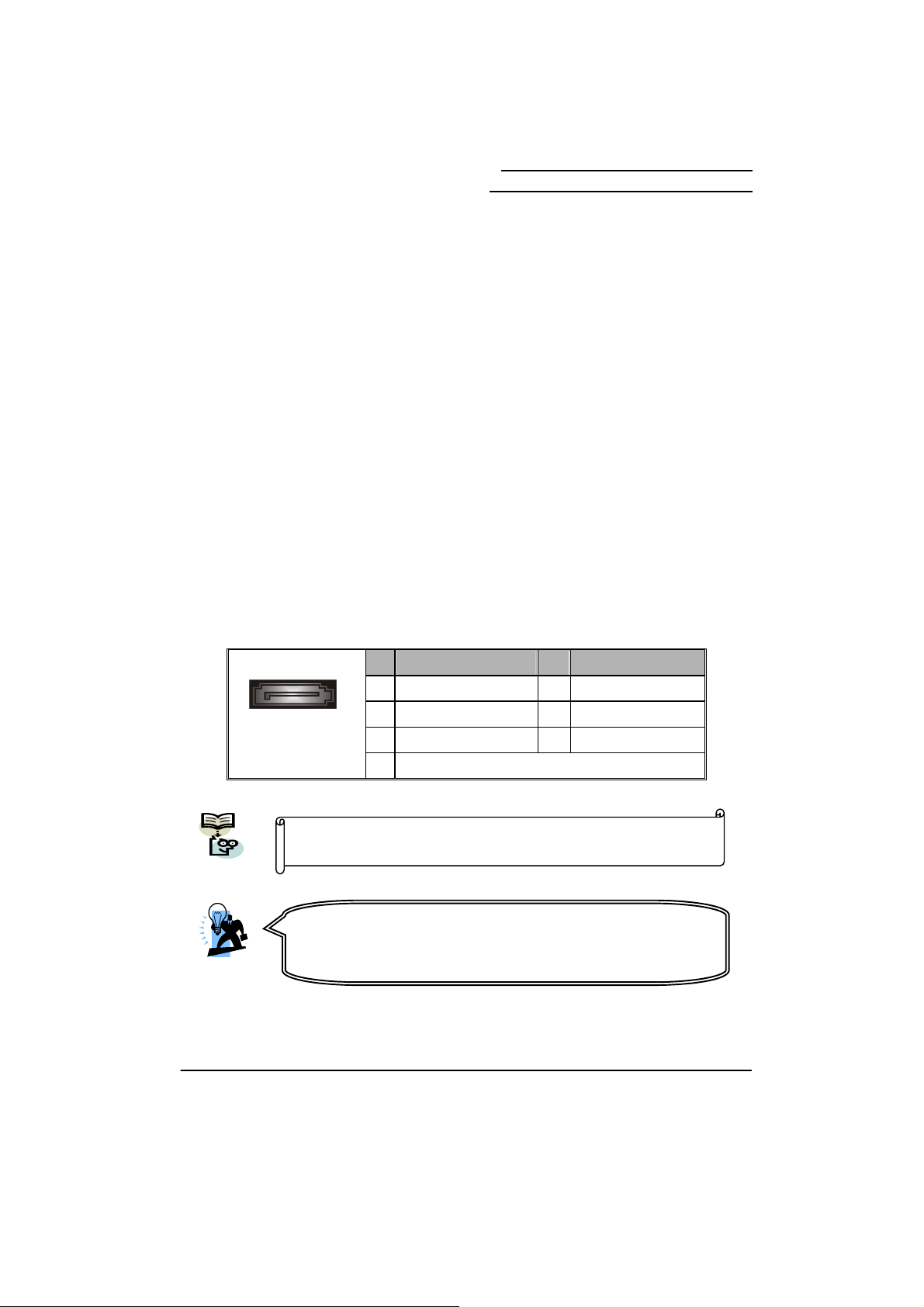
Floppy Disk Drive Connector: FLOPPY
These mainboards provide a standard floppy disk drive connector (FDD) that supports 360KB/
720KB/ 1.2MB/ 1.44MB/ 2.88 MB floppy disk drives using a FDD ribbon cable.
Hard Disk Drive Connectors: IDE
These mainboards provide one IDE connector that supports Ultra ATA 33/66/100/133 IDE
devices. You can attach a maximum of two IDE devices, such as hard disk drive (HDD),
CD-ROM, DVD-ROM, etc. using an IDE ribbon cable.
In general, two IDE devices can be attached onto one IDE connector. If you attach two IDE
HDDs, you must configure one drive as the master and the other one as the slave. In this case,
one optical device i.e., CD-ROM, DVD-ROM…etc. should be attached to this connector as
well.
SATA II Connector: SATA A0/A1/B0/B1/C0/C1
The six SATA II connectors support 3 Gbps transmit rate, and one SATA connector only can
attach one SATA HDD of each time using SATA cables.
SATA A0/ A1/ B0/
B1/ C0/ C1
This mainboard supports RAID 0/ 1/ 0+1/ 5/ JBOD mode; refer
Appendix II for more information.
Pin Assignment Pin Assignment
1 GND 2 TX+
1
3 TX- 4 GND
5RX+ 6 RX-
7 GND
Attention
The FDD/ IDE cable is designed and should be attached with a
specific direction. One edge of the cable will usually in color such
as red, to indicate that should line up with the header pin-1.
13
Page 18
Mainboard nForce 680i SLI/
Mainboard nForce 680i LT SLI
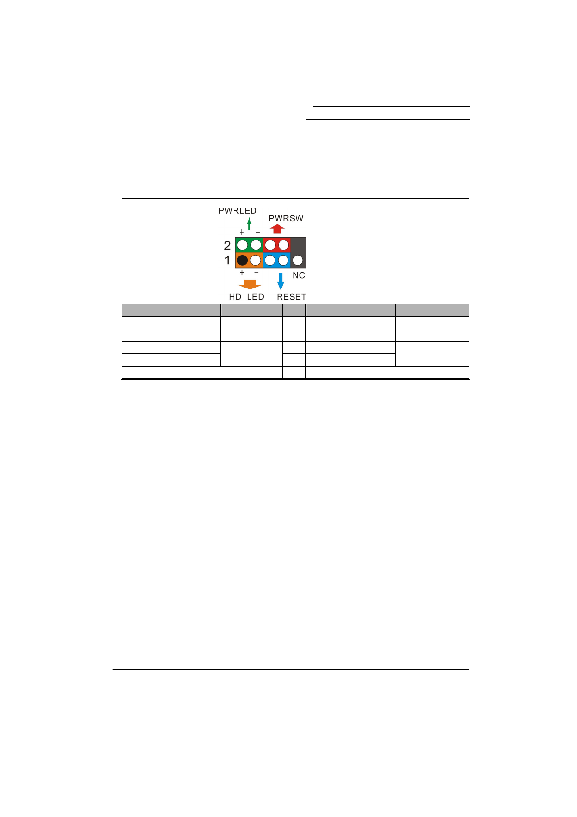
Front Panel Headers: FRONTPNL
Pin Assignment Function Pin Assignment Function
1 HD_PWR (+) 2 HDR_BLNK_GRN
3 HAD#
5 GND 6 SWITCH_ON#
7 FP_RESET#
9 N/C 10 Key
Hard Disk LED Header (Orange): HD_LED
If your case front panel has a hard drive LED cable, attach it to this header. The LED will
flicker when there is hard disk drive activity.
Reset Switch Header (Blue): RESET
This header can be attached to a momentary SPST switch (reset button) cable on your case
front panel. The switch is normally left open. When the switch closed, it will cause the
mainboard to reset and run the POST (Power-On Self Test).
Power LED Header (Green): PWRLED
These mainboards provide a 2-pin power LED header. If there is a 2-pin power LED cord on
your case front panel, you can attach it to the 2-pin power LED header. Then the power LED
will illuminate while the system is powered on.
Power Switch Header (Red): PWRSW
This header can be attached to a power switch cable on your case front panel. You can turn
your system on or off by pressing the button attached to this power switch cable.
Hard Disk LED
(HD_LED)
Reset Switch
(RESET)
FRONTPNL
4 HDR_BLNK_YEL
8 GND
Front Panel Light
(PWRLED)
Power Switch
(PWRSW)
14
Page 19
Mainboard nForce 680i SLI/
Mainboard nForce 680i LT SLI
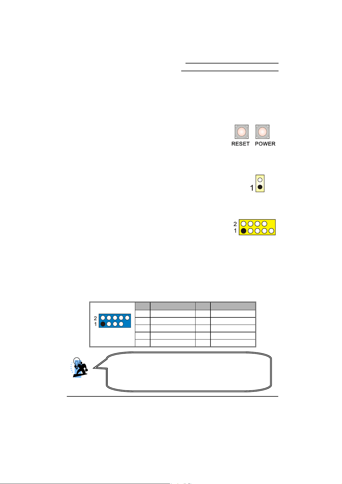
EZ Control Button
Onboard Buttons: POWER, RESET
These mainboard provide one Power Switch and one Reset Switch
buttons for your convenience to turn on or restart your system. If
pressing one of them, then you can start your computer easily before
the mainboard is set into the case.
Headers & Jumpers
Case Open Warning Header: CASE OPEN
This header is used to warn the user when the computer case has been
previously opened. Please connect the header with a cable to your case
directly. (Make sure that your computer case provides this “case open”
cable.)
Serial Interface Header: COM1
These mainboards provide one COM1 header for you to connect an
external serial connector on the back panel of your case. Attaching the
serial connector by a cable (Optional) onto this header, then you can
use the serial connector to attach with a mic, modem or other
peripheral device.
Front USB Headers: USB6/7, USB8/9
These mainboards provide six (or four) onboard USB 1.1/2.0 ports on the back panel that
attach to USB devices. There are two additional USB headers that can be connected by
cables to four more USB ports on the front panel of your case giving you a possible ten (or
eight) USB ports. 《nForce 680i LT SLI supports four onboard USB 2.0/1.1 ports on
the back panel.》
USB6/7/8/9
Attention
If you are using a USB 2.0 device with Windows® XP, you will need to
install the USB 2.0 driver from the Microsoft
Service pack 1 (or higher) for Windows
driver.
Pin Assignment Pin Assignment
1 5V_Dual 2 5V_Dual
3 D- 4 D-
5 D+ 6 D+
7 GND 8 GND
9 Key 10 N/C
®
website. If you are using
XP, you will not have to install the
CASE OPEN
COM1
15
Page 20
Mainboard nForce 680i SLI/
Mainboard nForce 680i LT SLI
IEEE1394 Header: IEEE1394
These mainboards provide one onboard IEEE1394 port on the back panel of your case. One
additional IEEE1394 header on the mainboard for one more port on the front panel is allowed.
Please connect the header by a cable for use with compatible devices.
Pin Assignment Pin Assignment
1 TPA+ 2 TPA3 GND 4 GND
IEEE1394
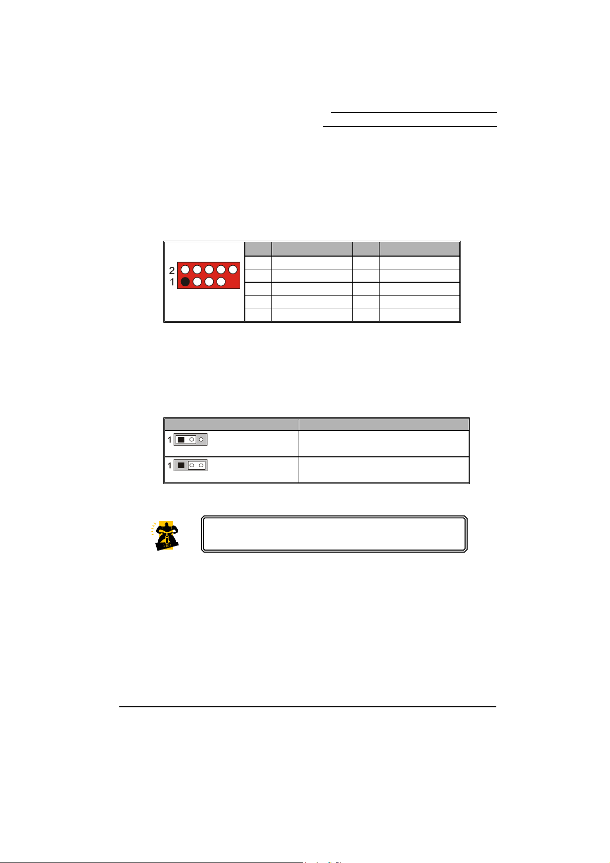
Clear CMOS Jumper: CLR_CMOS
5 TPB+ 6 TPB7 +12V 8 +12V
9 Key 10 GND
The “Clear CMOS” function is used when you are unable boot your system and need to reset
the BIOS settings (CMOS settings) back to the manufacturer’s original settings. This is also a
way to reset the system password if you have forgotten it.
CLR_CMOS Assignment
Pin 1-2 Closed
Pin 2-3 Closed
Note: Close stands for putting a jumper cap onto two header pins.
The following steps explain how to reset your CMOS
configurations when you forgot a system password.
1. Turn off your system and disconnect the AC power cable.
Clear CMOS Data
Normal (Default)
2. Set CLR_CMOS header to OFF (1-2 Closed).
3. Wait several seconds.
4. Set CLR_CMOS header to ON (2-3 closed).
5. Connect the AC power cable and turn on your system.
6. Reset your new password.
16
Page 21
Mainboard nForce 680i SLI/
Mainboard nForce 680i LT SLI
Audio Configuration
Front Audio Header: FP AUDIO
The audio header supports High Definition Audio standard and provides two kinds of audio
output choices, the Front Audio and the Rear Audio. The front audio supports re-tasking
function.
Slots
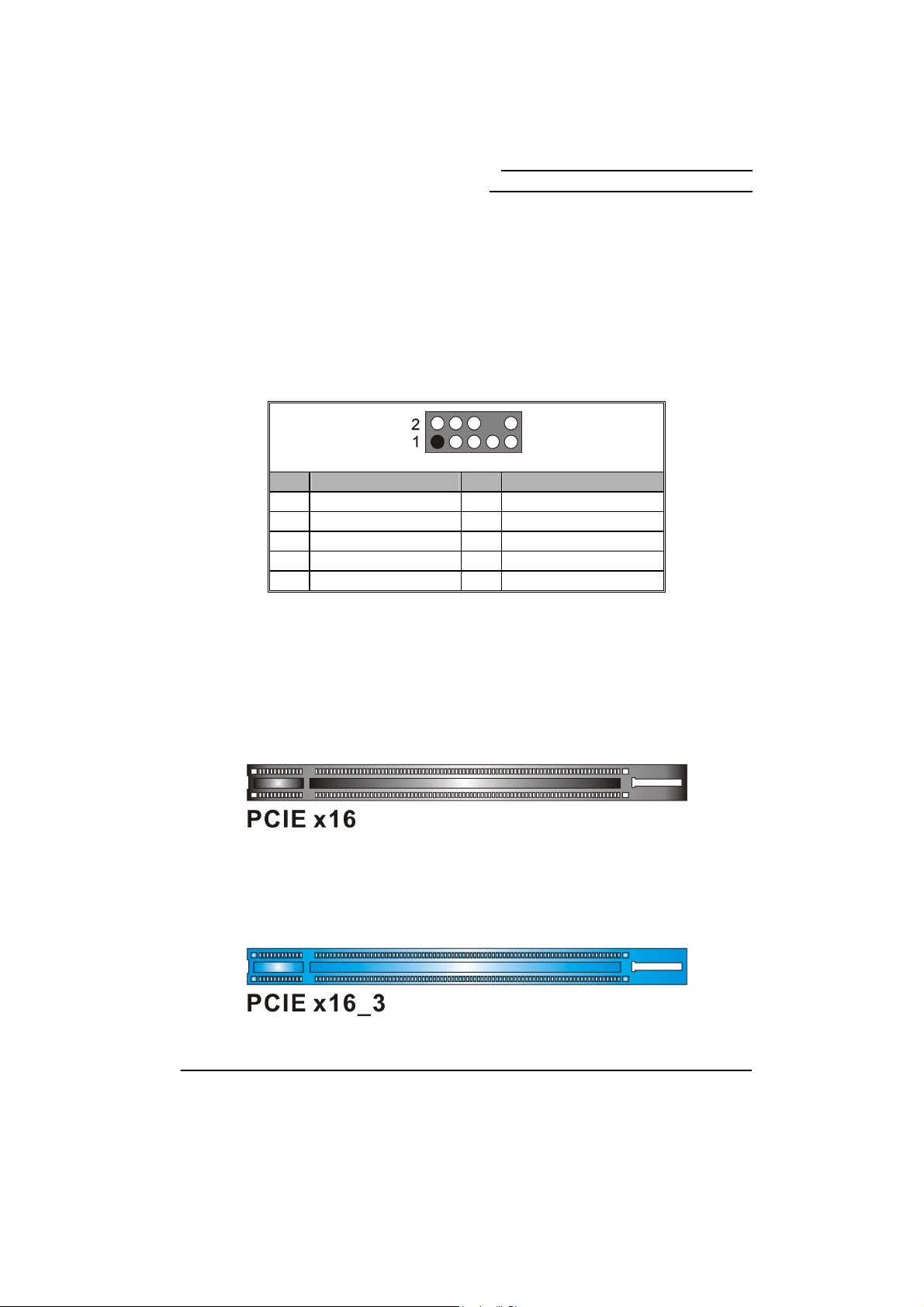
PCI-Express x16 Interface slot: PCIE x16_1/ PCIE x16_2
These mainboards provide two PCI-Express x16 slots which support one-way bandwidth up to
4 GB/s. They are also allowed to install two identical SLI-ready PCI-Express graphics cards to
enable SLI Technology for better graphics performance.
Pin Assignment Pin Assignment
PORT1_L
1
PORT1_R
3
PORT2_R
5
SENSE_SEND
7
PORT2_L
9
FP AUDIO
2
4
6
8
10
AUD_GND
PRECENCE_J
SENSE1_RETURN
Key
SENSE2_RETURN
PCI-Express x8 Interface slot: PCIE x16_3 nForce 680i SLI only
The nForce 680i SLI allows you to install an external graphics card, which the PCI-Express x8
interface, supporting one-way bandwidth up to 2 GB/s, is compatible to this PCIE x16_3 slot.
17
Page 22
Mainboard nForce 680i SLI/
Mainboard nForce 680i LT SLI
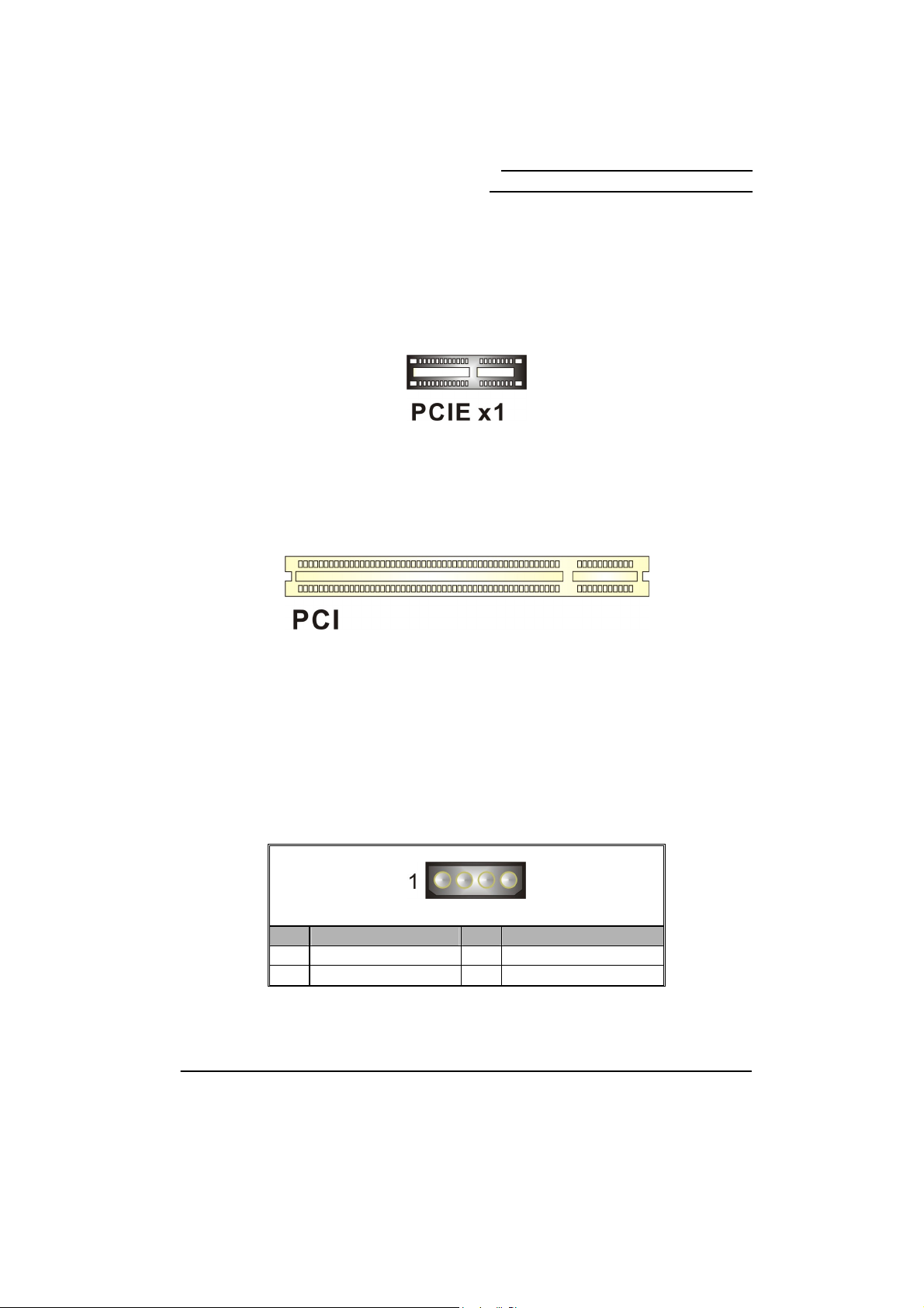
PCI-Express x1 Interface slots: PCIE x1_1/ PCIE x1_2
The PCIE x1_1/ PCIE x1_2 slots are the PCI-Express x1 interface slots which can be
supported up to x1 mode. You can insert expansion cards which are PCI-E x1 compatible onto
these slots.
PCI Interface Slots: PCI1/2
PCI stands for Peripheral Component Interconnect, which is a bus standard for installing
expansion cards such as network card, SCSI card, etc. to these PCI slots.
Power Supply Attachments
Auxiliary Power for Graphics: AUX PWR
The 4-pin connector is an auxiliary power connection for graphics card. Exclusive power for
the graphics card provides better graphics performance.
Pin Assignment Pin Assignment
+5V
1
GND
3
AUX PWR
2
4
GND
+12V
18
Page 23
Mainboard nForce 680i SLI/
A
Mainboard nForce 680i LT SLI
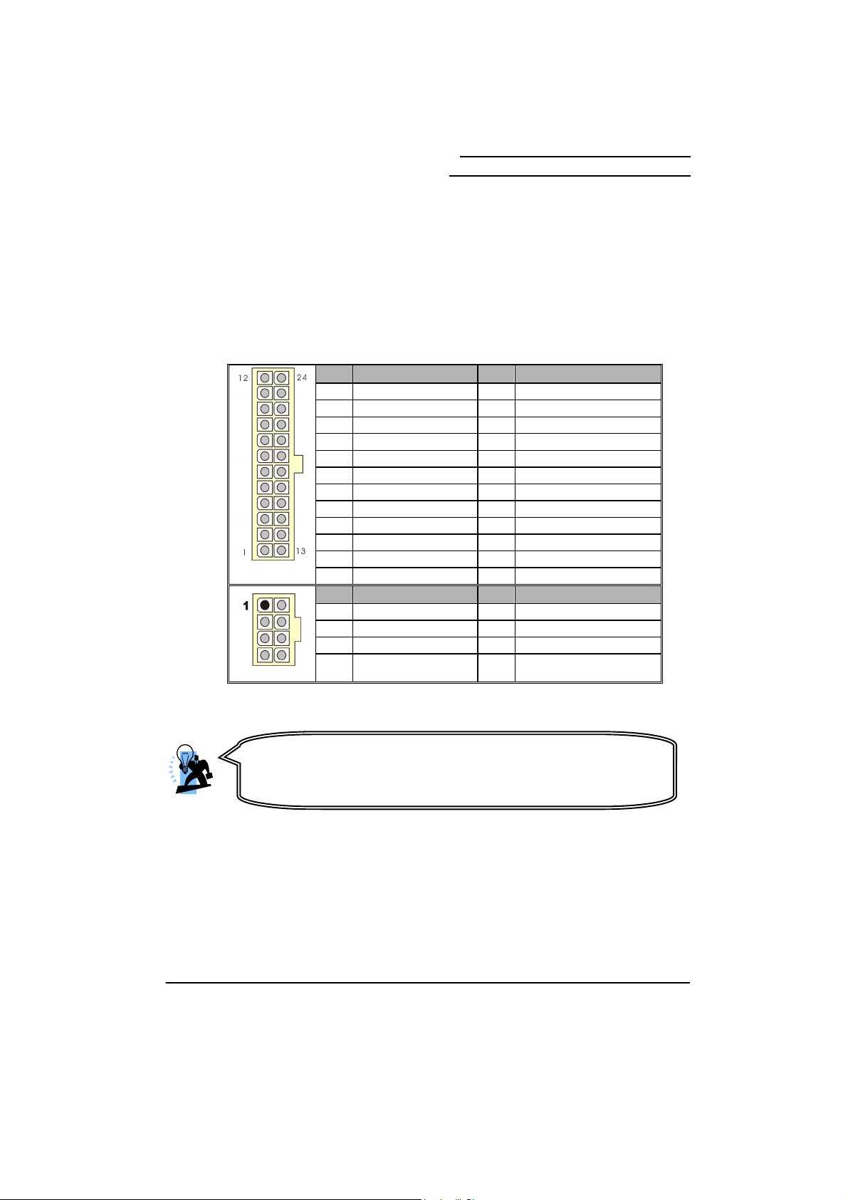
ATX Power Connector: ATXPWR, ATX12V
This mainboard provides two ATX power connectors, a 24-pin ATXPWR connector and an
8-pin ATX12V connector. You must use a power supply that has both of these connectors and
both connectors must be attached before the system is powered on. These power connectors
support several power management functions such as the instant power-on function. The
connector pins are described below.
Pin Assignment Pin Assignment
1 +3.3V 13 +3.3V
2 +3.3V 14 -12V
3 GND 15 GND
4 +5V 16 PS_ON
5 GND 17 GND
6 +5V 18 GND
7 GND 19 GND
8 PWROK 20 RSVD
9 +5V_AUX 21 +5V
10 +12V 22 +5V
ATXPWR
11 +12V 23 +5V
12 +3.3V 24 GND
Pin Assignment Pin Assignment
1 GND 5 +12V
2 GND 6 +12V
3 GND 7 +12V
ATX12V
ttention
In general, power cords are designed and should be attached with a
specific direction. The black wire of the power cord is Ground and
should be attached onto the header location of Ground.
4 GND 8 +12V
19
Page 24
Mainboard nForce 680i SLI/
Mainboard nForce 680i LT SLI
Chapter 2. BIOS Setup
Introduction
This section describes PHOENIX-AWARD™ BIOS Setup program which resides in the BIOS firmware.
The Setup program allows users to modify the basic system configuration. The configuration information is
then saved to CMOS RAM where the data is sustained by battery after power-down.
The BIOS provides critical low-level support for standard devices such as disk drives, serial ports and
parallel ports. As well, the BIOS controls the first stage of the boot process, loading and executing the
operating system.
The PHOENIX-AWARDTM BIOS installed in your computer system’s ROM is a custom version of an
industry standard BIOS. This means that it supports the BIOS of Intel
This version of the PHOENIX-AWARDTM BIOS includes additional features such as virus and password
protection as well as special configurations for fine-tuning the system chipset. The defaults for the BIOS
values contained in this document may vary slightly with the version installed in your system.
Key Function
In general, you can use the arrow keys to highlight options, press <Enter> to select, use the
<PgUp> and <PgDn> keys to change entries, press <F1> for help and press <Esc> to quit.
The following table provides more detail about how to navigate within the BIOS Setup
program.
Keystroke Function
Up arrow Move to previous option
Down arrow Move to next option
Left arrow Move to the option on the left (menu bar)
Right arrow Move to the option on the right (menu bar)
Esc Main Menu: Quit without saving changes
Move Enter Move to the option you desire
PgUp key Increase the numeric value or enter changes
PgDn key Decrease the numeric value or enter changes
+ Key Increase the numeric value or enter changes
- Key Decrease the numeric value or enter changes
Esc key Main Menu – Quit and do not save changes into CMOS
F1 key General help on Setup navigation keys
F5 key Load previous values from CMOS
F7 key Load the defaults from BIOS default table
F10 key Save all the CMOS changes and exit
Submenus: Exit Current page to the next higher level menu
Status Page Setup Menu and Option Page Setup Menu – Exit
Current page and return to Main Menu
®
based processors.
20
Page 25

Main Menu
Mainboard nForce 680i SLI/
Mainboard nForce 680i LT SLI
Standard CMOS Features
Include all the adjustable items in standard compatible BIOS.
Advanced BIOS Features
Include all the adjustable items of Award special enhanced features.
Advanced Chipset Features
Include all the adjustable items of chipset special features.
Integrated Peripherals
Include all onboard peripherals.
Power Management Setup
Include all the adjustable items of Green function features.
21
Page 26

Mainboard nForce 680i SLI/
Mainboard nForce 680i LT SLI
PnP/PCI Configurations
Include all configurations of PCI and PnP ISA resources.
System Monitor
It is for monitoring the system status such as temperature, voltage, and fan speeds.
Load Defaults
It can load the preset system parameter values to set the system in its stable performance
configurations.
Set Password
Set change or disable password. It allows you to limit access to the system and/or BIOS setup.
Save & Exit Setup
Save CMOS value settings to CMOS and exit setup.
Exit Without Saving
All CMOS value changes and exit setup.
22
Page 27

Mainboard nForce 680i SLI/
Mainboard nForce 680i LT SLI
Chapter 3: Software Setup
Software List
Category Platform
NVIDIA® Chipset Driver
Realtek® Audio Driver
Attention
You don’t need to install the driver for USB 2.0
version if you are using Windows
Service Pack 2 (or higher).
Windows Vista/ XP
Windows Vista/ XP
®
XP with
Software Installation
Place the Driver CD into the CD-ROM drive and the Installation Utility will auto-run. You can
also launch the Driver CD Installation Utility manually by executing the Intel.exe program
located on the Driver CD. (For more details, please refer to the Readme.txt files that in each
folder of the Driver.)
The screen and images are only for general reference. The version of the screens you
received with your software may vary slightly.
1. When you insert the driver CD into the CD-ROM, you’ll see the screen as the picture
below. There are several driver buttons displayed in the “Driver Menu” screen, and you
can click on the drivers to install.
23
Page 28

Windows® Vista Driver
Mainboard nForce 680i SLI/
Mainboard nForce 680i LT SLI
Windows® XP (64bit) Driver
Attention
Before you install the Realtek Audio Driver on Windows
(64bit) operating system, please go to the Microsoft
install the update for enabling HD Audio.
®
®
website to
XP
24
Page 29

Windows® XP (32bit) Driver
Mainboard nForce 680i SLI/
Mainboard nForce 680i LT SLI
NVIDIA Chipset INF – It provides all drivers for the functions which built in
both the Northbridge/ Southbridge.
Realtek Audio Driver – It provides the driver of Realtek HD Audio CODEC.
25
Page 30

Mainboard nForce 680i SLI/
Mainboard nForce 680i LT SLI
2. Click on the “User Manual” button, you can choose the manual to read.
3. If you click the “Browse CD” button, you can browse all the files in the Driver CD.
Attention: Before you read manuals, you
must install the driver of Adobe Acrobat
Reader 6 to browse PDF files.
26
Page 31

Mainboard nForce 680i SLI/
Mainboard nForce 680i LT SLI
Chapter 4: Troubleshooting
Problem 1:
No power to the system. Power light does not illuminate. Fan inside power supply does not
turn on. Indicator lights on keyboard are not lit.
Causes:
1. Power cable is unplugged.
2. Defective power cable.
3. Power supply failure.
4. Faulty wall outlet; circuit breaker or fuse blown.
Solutions:
1. Make sure power cable is securely plugged in.
2. Replace cable.
3. Contact technical support.
4. Use different socket, repair outlet, reset circuit breaker or replace fuse.
Problem 2:
System inoperative. Keyboard lights are on, power indicator lights are lit, hard drive is active
but system seems “hung”
Causes: Memory DIMM is partially dislodged from the slot on the mainboard.
Solutions:
1. Power Down
2. Using even pressure on both ends of the DIMM, press down firmly until the module snaps
into place.
Problem 3:
System does not boot from the hard disk drive but can be booted from the CD-ROM drive.
Causes:
1. Connector between hard drive and system board unplugged.
2. Damaged hard disk or disk controller.
3. Hard disk directory or FAT is corrupted.
Solutions:
1. Check the cable running from the disk to the disk controller board. Make sure both ends are
securely attached. Check the drive type in the standard CMOS setup.
2. Contact technical support.
3. Backing up the hard drive is extremely important. Make sure your periodically perform
backups to avoid untimely disk crashes.
27
Page 32

Mainboard nForce 680i SLI/
Mainboard nForce 680i LT SLI
Problem 4:
System only boots from the CD-ROM. The hard disk can be read and applications can be
used but booting from the hard disk is impossible.
Causes: Hard Disk boot sector has been corrupted.
Solutions: Back up data and applications files. Reformat the hard drive. Re-install applications
and data using backup disks.
Problem 5:
Error message reading “SECTOR NOT FOUND” displays and the system does not allow
certain data to be accessed.
Causes: There are many reasons for this such as virus intrusion or disk failure.
Solutions: Back up any salvageable data. Then performs low level format, partition, and then a
high level format the hard drive. Re-install all saved data when completed.
Problem 6:
Screen message says “Invalid Configuration” or “CMOS Failure.”
Causes: Incorrect information entered into the BIOS setup program.
Solutions: Review system’s equipment. Reconfigure the system.
Problem 7:
The Screen is blank.
Causes: No power to monitor.
Solutions: Check the power connectors to the monitor and to the system.
Problem 8:
Blank screen.
Causes:
1. Memory problem.
2. Computer virus.
Solutions:
1. Reboot computer. Reinstall memory. Make sure that all memory modules are securely
installed.
2. Use anti-virus programs to detect and clean viruses.
Problem 9:
Screen goes blank periodically.
Causes: Screen saver is enabled.
Solutions: Disable screen saver.
28
Page 33

Mainboard nForce 680i SLI/
Mainboard nForce 680i LT SLI
Problem 10:
Keyboard failure.
Causes: Keyboard is disconnected.
Solutions: Reconnect keyboard. Replace keyboard if you continue to experience problems.
Problem 11:
No color on screen.
Causes:
1. Faulty Monitor.
2. CMOS incorrectly set up.
Solutions:
1. If possible, connect monitor to another system. If no color appears, replace monitor.
2. Call technical support.
Problem 12:
The screen displays “C: drive failure.”
Causes: Hard drive cable not connected properly.
Solutions: Check hard drive cable.
Problem 13:
Cannot boot the system after installing a second hard drive.
Causes:
1. Master/slave jumpers not set correctly.
2. Hard drives are not compatible / different manufacturers.
Solutions:
1. Set master/slave jumpers correctly.
2.Run SETUP program and select the correct drive types. Call drive manufacturers for
possible compatibility problems with other drives.
Problem 14:
Missing operating system on hard drive.
Causes: CMOS setup has been changed.
Solutions: Run setup and select the correct drive type.
Problem 15:
Certain keys do not function.
Causes: Keys jammed or defective.
Solutions: Replace keyboard.
29
Page 34

Mainboard nForce 680i SLI/
Mainboard nForce 680i LT SLI
Appendix I: 8/6/4/2 Channel Audio
Effect Setup
Channels Setup for Windows Vista
1. After entering the system, click the audio icon from the Windows Vista screen.
2. When your audio device is plugged, the system will detect it and show the “Speakers” tab
automatically. You can see the screen like the picture below.
3. You can choose “Stereo”, “Quadraphonic”, “5.1 Speaker” or “7.1 Speaker” by your
speakers in the “Speaker Configuration” item.
4. You can click the “Auto test” button to test your audio devices.
30
Page 35

Mainboard nForce 680i SLI/
Mainboard nForce 680i LT SLI
Channels Setup for Windows XP
1. After into the system, click the audio icon from the Windows XP screen.
2. Click “Audio I/O” button, you can see the screen like the picture below.
3. You can choose 2, 4, 6 or 8 channels by your speakers.
4. You can click the “Auto test” button to test your audio devices.
To take advantage of 7.1 Channel Audio Effects, you must use
audio software that supports this functionality. You must also
make sure your software is specifically configured for 7.1
Channel Audio Effect supoort.
31
Page 36

Mainboard nForce 680i SLI/
Mainboard nForce 680i LT SLI
Appendix II: RAID Setup
Introduction to RAID
RAID (Redundant Array of Independent Disks) technology is a sophisticated disk
management system that manages multiple disk drives. It enhances I/O performance and
provides redundancy in order to prevent the loss of data in case of individual disk failure. The
RAID facility on this board provides RAID 0, RAID 1, RAID 0+1, RAID JBOD, and RAID 5.
Disk Striping (RAID 0)
Striping is a performance-oriented, non-redundant disk storage technology. With RAID striping,
multiple disks are used to form a larger virtual disk. Data is then striped or mapped across all
the physical disks. In this way, multiple I/O operations can be executed in parallel, enhancing
performance. Striping does not provide fault tolerance. The minimum number of hard drives
for RAID 0 is 2.
Disk Mirroring (RAID 1)
With Disk Mirroring there are redundant disks that mirror the primary disks. Data that is written
to the primary disks are also written to the redundant disks. This redundancy provides fault
tolerant protection from a single disk failure. If a read/write failure occurs on one drive, the
system can still read and write data using the other drive. The minimum number of drives for a
RAID 1 configuration is 2. You are required to use an even number of drives.
Disk Striped Mirroring (RAID 0+1)
This mode combines both the performance benefits of RAID 0 with the fault tolerance of RAID
1. The minimum number of drives for RAID 0+1 configuration is 4 drives. This configuration
also requires an even number of drives.
Note: All mirrored configurations or striped/mirrored configurations should use drives of the
same size.
RAID SPAN (RAID JBOD)
RAID SPAN allows JBOD (Just a Bunch Of Disks) configurations which simply uses multiple
disks to form a larger virtual disk without any other specialized disk management functionality.
RAID SPAN is not considered a standard RAID implementation.
Disk Rotating Parity Array (RAID 5)
RAID 5 is one of the most popular implementations of RAID. It utilizes the configurations of
Byte Stripping and Block Stripping, and writes the data to multiple disks. The minimum number
of drives for a RAID 5 configuration is 3. It possesses the
information; therefore, once a read/write failure occurs on one drive,
still read and write data using the other drive.
substantially decrease in a write-heavy environment.
stripe error correction
the system can
As result, the performance of RAID 5 can
32
Page 37

Mainboard nForce 680i SLI/
Mainboard nForce 680i LT SLI
Before you create a RAID Array
Before you configure your RAID Array, you have to enable the “RAID” option in the BIOS
Setup Utility.
Integrated Peripherals >> RAID Config >> RAID Enable >> Save & Exit Setup
1. When the screen below displays, press <Delete> to enter the BIOS setup screen.
2. Move the arrow keys to the "Integrated Peripherals" item and press <Enter> .
33
Page 38

Mainboard nForce 680i SLI/
Mainboard nForce 680i LT SLI
3. After entering the sub-menu, arrow down to the "RAID Config"item. Press <Enter>.
4. Enable the “RAID Enable” item and then select the SATA ports with disks that you want to
use for RAID. Press <Esc> to exit this screen.
34
Page 39

Mainboard nForce 680i SLI/
Mainboard nForce 680i LT SLI
5. At the main screen arrow over to the "Save & Exit Setup" item. Press <Enter>.
6. Press <Y>, and then press <Enter> to finish the setup.
NVIDIA RAID Setup Utility Configuration
The NVIDIA RAID Setup Utility is used to configure RAID disk management into your hard
disks. This section will explain how to setup and maintain your RAID disk drives.
35
Page 40

Mainboard nForce 680i SLI/
Mainboard nForce 680i LT SLI
1. When the system boots up during the POST (Power-On Self Test), you will be given an
opportunity to enter the NVIDIA RAID Setup Utility when the screen prompts you with the
following message.
“Press F10 to enter RAID setup utility…”
2. Press the <F10> key to enter the NVIDIA RAID Setup Utility (note that you will only have a
short window of time to press <F10> before the system continues the next step of the boot
process). The NVIDIA RAID Setup Utility main screen will display as shown below. In
addition, you will see all the SATA HDDs connected to your computer.
36
Page 41

Item Description
á RAID Mode Choose the RAID Mode you wish to configure.
Mainboard nForce 680i SLI/
Mainboard nForce 680i LT SLI
Attention
The “Port” and “Disk Model”, shown on these screens
represent the disk drives installed on the PATA or SATA
connectors and are sample data only. The actual data that
displays on your screen will likely vary.
• RAID 0 (Striped)
• RAID 1 (Mirrored)
• RAID 0+1 (Striped Mirror)
• JBOD (Spanned)
• RAID 5
Your choice will depend on the RAID Mode that best
fits your needs for either performance, redundancy or
both.
37
Page 42

Mainboard nForce 680i SLI/
Mainboard nForce 680i LT SLI
á Stripe Block Stripe block size will directly affect performance when data
is written to or read by your system.
• 4K
• 8K
• 16K
• 32K
• 64K
• 128K
• Optimal
This item is not available for RAID 1 and JBOD arrays.
38
Page 43

Mainboard nForce 680i SLI/
Mainboard nForce 680i LT SLI
Creating a New Array
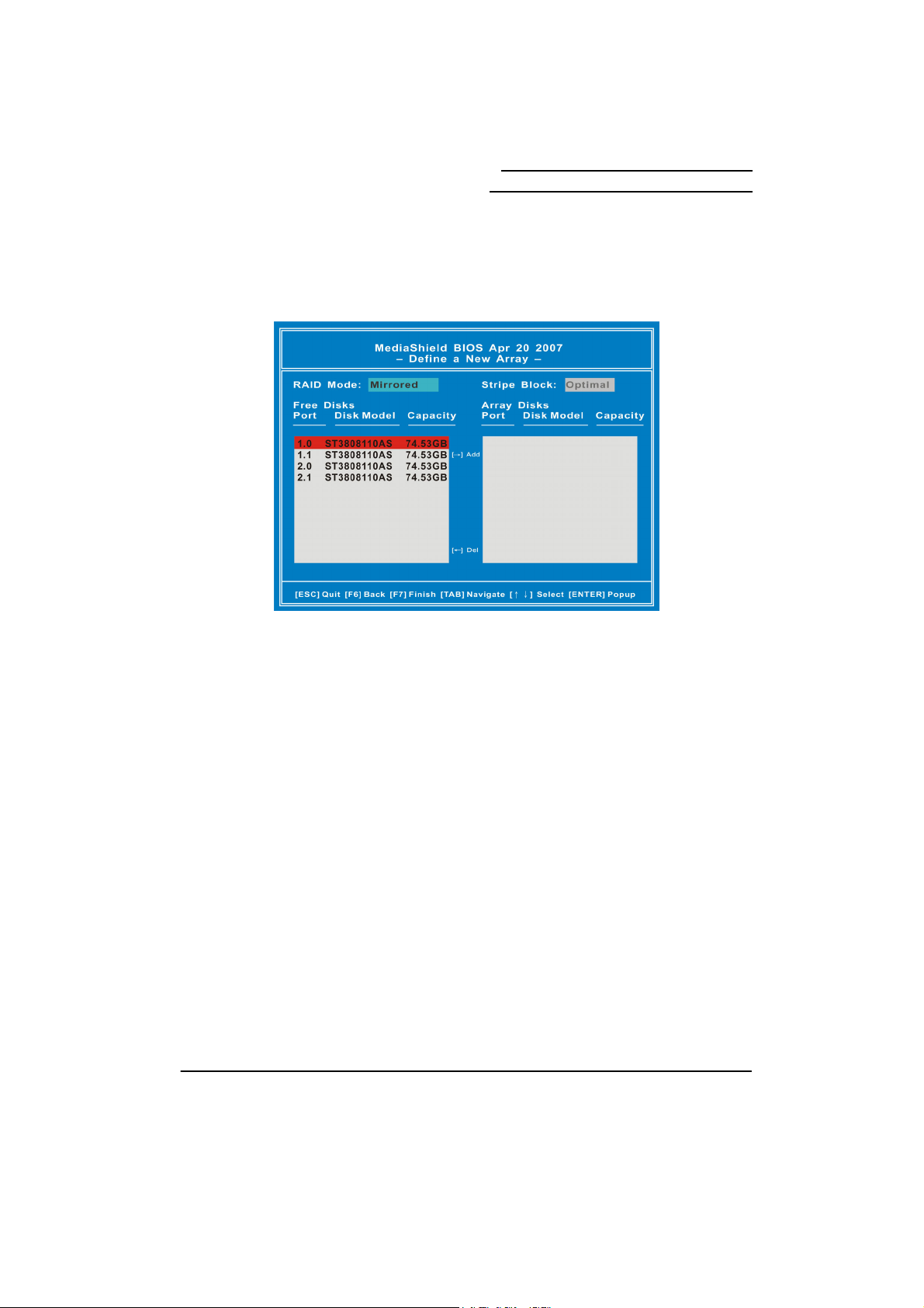
1. The screen you will see upon initial configuration is the “Define a New Array” screen.
<Tab> over to the “RAID Mode” item and press <Enter>. According to your configuration
requirements, select “Mirrored” (RAID 1), “Striped” (RAID 0), “Striped Mirror“ (RAID 0+1),
“Spanned” (JBOD), or “RAID 5” in the drop-down menu. Then hit <Enter>. The example
here is “RAID 0 (Striped)”.
2. Next, <Tab> over to the “Stripe Block” item and press <Enter>. You can select the stripe
block size for your array which will affect performance. It’s recommended that you select
“Optimal”. Press <Enter>.
39
Page 44

Mainboard nForce 680i SLI/
Mainboard nForce 680i LT SLI
3. <Tab> over to the “Free Disks” selection box, and use the up/down arrow keys to select
disks for your RAID array. Use the right-arrow key to move selected disks to the “Array
Disks” section (the selected drive will be highlighted). You can use the left-arrow key to
reverse your selection.
40
Page 45

Mainboard nForce 680i SLI/
Mainboard nForce 680i LT SLI
4. After all of the options are properly configured, press <F7>. A confirmation box will display
as shown below. Hit <Y> to continue the RAID array creation.
5. An alert box will appear as shown below. Press <Y> to clear the Master Boot Record and
complete the RAID array creation.
41
Page 46

Mainboard nForce 680i SLI/
Mainboard nForce 680i LT SLI
6. In the next page, you will see the “Array List” screen as shown below. You can press
<Enter> to view the details.
7. The “Array Detail” screen provides you all the information of the RAID array you created.
You can press <Enter> to go back to the previous page. If you want to exit NVIDIA RAID
Setup Utility, press <Enter> and then hit <Ctrl-X> to restart your computer.
42
Page 47

Mainboard nForce 680i SLI/
Mainboard nForce 680i LT SLI
8. When you see the screen below, please confirm the information about the RAID arrays you
have created.
■ If you select a RAID Mode with wrong hard disk numbers…
1. For example, if you select “Mirrored” configure four hard disks into your array disks, and
then you press <F7> go to the next step.
43
Page 48

Mainboard nForce 680i SLI/
Mainboard nForce 680i LT SLI
2. Then you will see an alert box to notify you that you selected an invalid number of disks. In
a mirrored array, you can only configure two disks at one time. You must press <Enter> to
go back to the main screen to reconfigure your options again.
The RAID Introduction to this manual explains disk requirements for each RAID
configuration.
44
Page 49

Mainboard nForce 680i SLI/
Mainboard nForce 680i LT SLI
Deleting Array
1. If you want to delete an existing array, go to the “Array Detail screen as below. Press <D>.
2. An alert box will display for your confirmation to delete the array. Press <Y> to delete.
45
Page 50
Mainboard nForce 680i SLI/
Mainboard nForce 680i LT SLI
3. After the array is deleted successfully, you will return to the main screen where you can
re-create a new array as shown below.
46
Page 51

Mainboard nForce 680i SLI/
Mainboard nForce 680i LT SLI
Configuring a Bootable Array
Use the up/down arrow keys to select an array. Then press <B> to specify the selected
array as a bootable array. You will see a special symbol, “√”, marked in the Boot item of the
highlighted array.
■ When there is only one RAID array…
■ When there are two RAID arrays or more, you can only select one.
47
Page 52

Mainboard nForce 680i SLI/
Mainboard nForce 680i LT SLI
Install Windows® XP OS onto your RAID HDDs
This section will explain how to install the Windows® XP operating system onto your RAID
drives. The installation steps below will assume that your HDDs have already been
attached to the SATA connectors, and your RAID arrays have already been configured
using the NVIDIA RAID Setup Utility (NVIDIA RAID Setup Utility Configuration section).
Download the NVIDIA RAID driver from the Albatron website.
1. Go to the Albatron website: http://www.albatron.com.tw
2. Move your mouse pointer to the “Product Info” menu item and then click the
“Mainboard” item in the drop-down menu.
48
Page 53

Mainboard nForce 680i SLI/
Mainboard nForce 680i LT SLI
3. Select your mainboard. The example used below is “NF 680i SLI” mainboard.
4. Click “Driver” as shown below on the left panel. Click the download icon to download the
NVIDIA RAID driver (You should download the RAID driver according to your operating
system). The picture below illustrates a selection for a system using a “Windows XP 32-bit
Operating System”.
49
Page 54

Mainboard nForce 680i SLI/
Mainboard nForce 680i LT SLI
5. Press the “Save” button to download the RAID zip file. You must unzip the file and save
the files onto media that you can use on an existing storage device on your computer (e.g.
floppy disk drive).
50
Page 55

Mainboard nForce 680i SLI/
Mainboard nForce 680i LT SLI
Install Windows® XP
1. During the Windows® XP installation, a “Windows Setup” screen will prompt you with
“Press F6 if you need to install third party SCSI or RAID driver”. Press <F6>.
2. Press <s> when setup asks if you want to specify an additional device.
51
Page 56

Mainboard nForce 680i SLI/
Mainboard nForce 680i LT SLI
3. Insert the media which includes the “RAID Driver” into your computer. Press <Enter> to
locate the appropriate OS device driver. You will install two drivers.
4. Select the “NVIDIA RAID CLASS DRIVER (required)” and press <Enter> to locate this
driver.
52
Page 57

Mainboard nForce 680i SLI/
Mainboard nForce 680i LT SLI
5. When you see the screen shown as below again, press <s> to download the second RAID
driver.
6. Select the “NVIDIA nForce Storage Controller (required)” and also, press <Enter>.
53
Page 58

Mainboard nForce 680i SLI/
Mainboard nForce 680i LT SLI
7. You have finished RAID drivers installation. Press <Enter> to continue the Windows® XP
setup process.
8. Follow the setup instructions and select the partition and file system where you want to
install the operating system files.
9. After setup examines your disks, it will copy files to the Windows® XP installation folders
and restart the system. After the system reboots, the setup program will continue with the
installation all the way to completion.
10. Wait until Windows® XP finishes installing devices, regional settings, networking settings,
components, and any other remaining tasks. Reboot the system if you are asked to do so.
54
Page 59

Mainboard nForce 680i SLI/
Mainboard nForce 680i LT SLI
Install Windows® Vista OS onto your RAID HDDs
This section will explain how to install Windows® Vista operating system onto your RAID
drives. The installation steps below will assume that your HDDs have already been
attached to the SATA connectors, and your RAID arrays have already been configured
using the NVIDIA RAID Setup Utility (NVIDIA RAID Setup Utility Configuration section).
Download the NVIDIA RAID driver from the Albatron website.
1. Go to the Albatron website: http://www.albatron.com.tw
2. Move your mouse pointer to the “Product Info” menu item and then click the
“Mainboard” item in the drop-down menu.
55
Page 60

Mainboard nForce 680i SLI/
Mainboard nForce 680i LT SLI
3. Select your mainboard. The example used below is “NF 680i SLI” mainboard.
4. Click “Driver” as shown below on the left panel. Click the download icon to download the
NVIDIA RAID driver (You should download the RAID driver according to the operating
system). The picture below illustrates “Windows Vista 32-bit Operating System”.
56
Page 61

Mainboard nForce 680i SLI/
Mainboard nForce 680i LT SLI
5. Press the “Save” button to download the RAID zip file. You must unzip the file and save
the files to media that you can use on an existing storage device on your computer (floppy
disk drive, or USB Flash Drive).
57
Page 62

Mainboard nForce 680i SLI/
Mainboard nForce 680i LT SLI
Install Windows® Vista
1. During a Windows® Vista installation, there will be an item “Load Driver”. Click on it and
then insert the media containing the RAID Driver files into your computer. You will install
two drivers.
2. Click on “Browse” to browse into the folders of the media to locate the folder with the files.
58
Page 63

Mainboard nForce 680i SLI/
Mainboard nForce 680i LT SLI
3. Select the media which includes the RAID Drivers.
4. The example here is “floppy disk drive”. Make sure you have inserted the floppy disk
including the RAID Drivers. Select “Floppy Disk Drive(A:)”. Click “OK” to load the RAID
Drivers. The system will scan for the drivers automatically.
59
Page 64

Mainboard nForce 680i SLI/
Mainboard nForce 680i LT SLI
5. Select the “NVIDIA nForce RAID Controller” and click “Next” to locate this driver. Please
wait until finished.
6. When you go back to the screen shown as below, click “Load Driver” again to download
the second RAID driver.
60
Page 65

Mainboard nForce 680i SLI/
Mainboard nForce 680i LT SLI
7. Click on “Browse” to browse into the folders of the media to locate the folder with the files.
8. Select the media which includes the RAID Drivers.
61
Page 66

Mainboard nForce 680i SLI/
Mainboard nForce 680i LT SLI
9. Select “Floppy Disk Drive(A:)” and click “OK” to load the RAID Drivers. The system will
rescan for the drivers automatically.
10. Select the “NVIDIA nForce Serial ATA Controller” and click “Next” to continue. Please
wait until finished.
62
Page 67

Mainboard nForce 680i SLI/
Mainboard nForce 680i LT SLI
11. You will return to the “Install Windows” screen to continue with the installation. Follow the
setup instructions and select the partition where you want to install the operating system
files.
12. After setup examines your disks, it will copy files to the Windows® Vista installation folders
and restart the system. After the system is rebooted, the setup program will continue with
the installation all the way to completion.
13. Wait until Windows® Vista finishes installing devices, regional settings, networking settings,
components, and any other remaining tasks. Reboot the system if you are asked to do so.
63
Page 68

Mainboard nForce 680i SLI/
Mainboard nForce 680i LT SLI
Rebuilding a RAID Mirrored Array
This section will illustrate how to replace a failed drive with a new one, and rebuild the array
to restore lost data on the newly installed drive. Rebuilding only applies to fault-tolerant
arrays which are RAID 1, RAID 0+1, and RAID 5 arrays.
1. Before rebuilding an array, you must connect new hard disk(s) onto your computer.
2. Power on your computer. When the system boots up during the POST (Power-On Self
Test), you will be given an opportunity to enter the NVIDIA RAID Setup Utility when the
screen prompts you with the following message.
3. Press <F10> key to enter the NVIDIA RAID Setup Utility (note that you will only have a
short window of time to press <F10> before the system continues the next step of the boot
process).
4. Go to the screen shown as below. Press <Enter>.
“Press F10 to enter RAID setup utility…”
64
Page 69

Mainboard nForce 680i SLI/
Mainboard nForce 680i LT SLI
5. You should see the existing RAID array on your system. Press <R> to rebuild the array.
6. The next screen will display as below. Use up/down arrow keys to select a free disk. Press
<A> to continue.
65
Page 70

Mainboard nForce 680i SLI/
Mainboard nForce 680i LT SLI
7. An alert box will display for your confirmation to rebuild array. Press <Enter> to go to the
next step.
8. A confirmation box will display as shown below. Hit <Y> to continue rebuilding the RAID
array.
66
Page 71

Mainboard nForce 680i SLI/
Mainboard nForce 680i LT SLI
9. You have successfully finished the setup of rebuilding an array in the “NVIDIA RAID Setup
Utility”. Press <Ctrl-X> to restart your computer.
10. During the boot process, you will see the screen below. Confirm the “Rebuild” information
as shown below.
67
Page 72

Mainboard nForce 680i SLI/
Mainboard nForce 680i LT SLI
11. The Rebuild process is automatic. You can check of the Rebuild in the following steps. Go
to to “Start → All Programs → NVIDIA Corporation → NVIDIA Control Panel →
Storage” under Windows.
12. A notification box will display to notify you rebuilding the array is started. Rebuilding the
array will take a while. Please wait until finished.
68
Page 73

Mainboard nForce 680i SLI/
Mainboard nForce 680i LT SLI
13. When the rebuilding is finished, make sure the “Status” item for your Rebuild Array shows
“Healthy”. You have now successfully rebuilt the RAID array.
69
Page 74

Mainboard nForce 680i SLI/
Mainboard nForce 680i LT SLI
Appendix III: SLI (Scalable Link
Interface) Setup
Introduction
NVIDIA SLI (Scalable Link Interface) is a revolutionary technology that allows two NVIDIA SLI
graphics cards to work together to deliver incredible 3D graphics performance.
Your new motherboard can support up to three PCI Express graphics cards, two linked using
SLI and one dedicated to CPU physics.
Determine Component and Operating System Needs
To build an NVIIDA SLI system, you are going to need the following components:
Two NVIDIA SLI-Ready certified PCI Express graphics cards
An NVIDIA SLI-Ready power supply
Microsoft® Windows® XP operating system
For a complete list of certified components and a matrix to determine the power supply
required for your particular graphic cards, go to:
http://www.slizone.com/content/slizone/build.html.
While NVIDIA recommends an SLI-Ready power supply, the following table provides some
general power supply recommendations based on testing performed in the NVIDIA SLI
validation lab.
Recommended Power Supplies
NVIDIA SLI System Type
High-End: GeForce 6800 Ultra 500W–550W, +12V @ 30A
Mid-Range: GeForce 6800 GT or 6800 420W–480W, +12V @ 25A
Entry-Level: GeForce 6600 GT 350W–420W, +12V @ 20A
If the power supply specifies two 12V windings (i.e. 12V1 and 12V2), add these numbers
together to check against the specifications described above.
For systems with the 6800 Ultra or 6800 GT, please make sure the power supply also contains
PCI Express auxiliary power supply connectors. If your power supply does not have a PCI
Minimum Recommended PCI
Express Power Supply
70
Page 75

Mainboard nForce 680i SLI/
Mainboard nForce 680i LT SLI
Express auxiliary connector (6-pin connector), please contact your graphics board partner for
an HDD-to-PCI Express power adaptor.
The NVIDIA SLI power supply recommendations are based on the following test
configurations:
High-End NVIDIA SLI Configuration:
Dual GeForce 6800 Ultra Graphics cards
Athlon 64 939-pin CPU or Intel Xeon
Two or more HDD, including RAID 0,1, 0+1 or 5 configurations
Two optical drives
PCI sound card
Mid-Range NVIDIA SLI Configuration:
Dual GeForce 6800 or GeForce 6800 GT Graphics cards
Athlon 64 939-pin CPU
Single HDD
Two optical drives
PCI sound card
Entry-Level NVIDIA SLI configuration:
Dual GeForce 6600 GT Graphics cards
Athlon 64 939-pin CPU
Single HDD
One optical drive
For a list of certified power supplies, go to:
http://www.slizone.com/content/slizone/build.html
Install Your NVIDIA SLI-Ready Parts
.
Now that you have obtained the necessary NVIDIA SLI-Ready parts, it is time to configure the
system. This procedure assumes you have already installed the motherboard. The NVIDIA
nForce 680i SLI motherboard has three PCI Express slots. The two outer slots (black) are
used for the SLI configuration. The middle slot (blue) is used for CPU physics and is not
configured into the SLI configuration.
71
Page 76

Mainboard nForce 680i SLI/
Mainboard nForce 680i LT SLI
Use the following procedure to build your NVIDIA SLI-Ready PC system:
SLI graphics cards in these slots
1. Install two SLI-Ready graphic cards into the two outer black PCI Express x16 slots on the
motherboard. Be sure to seat the graphic cards into the connectors.
Two SLI graphics
cards installed in
the outer two
(block) PCI
Express slots on
the motherboard.
Note the blue PCI
Express slot is
empty.
72
Page 77

Mainboard nForce 680i SLI/
Mainboard nForce 680i LT SLI
Three PCI Express
graphics cards
installed. Only the
two outer cards
will be SLI’ed
using the SLI
Connector
shipped in your
motherboard kit.
2. Connect the PCI Express supplementary power connectors from the system power
supply to each of the graphic cards:
From Power Supply
73
Page 78

Mainboard nForce 680i SLI/
Mainboard nForce 680i LT SLI
3. Install the NVIDIA SLI connector across the two outer graphics cards as shown below.
Each SLI-Ready graphics card has an SLI finger on the upper side of the card.
Install the SLI connector
Install NVIDIA SLI Software
onto the two outer cards.
Upon power up, the operating system recognizes the new NVIDIA SLI-Ready components
and displays the Found New Hardware message.
Your motherboard shipped with a set of drivers that you must install. Once these drivers are
installed, reboot your system.
As part of the NVIDIA Unified Driver Architecture, NVIDIA drivers include a full set of controls
for SLI systems.
74
Page 79

Mainboard nForce 680i SLI/
Mainboard nForce 680i LT SLI
Go to http://www.slizone.com/content/slizone/drivers.html and download the latest SLI
graphics drivers.
With the new drivers installed, reboot your system. After this reboot, the following SLI capable
system message displays to let you know that your hardware and software components have
been installed properly.
Click on this message to enable your NVIDIA SLI.
Enable NVIDIA SLI
At this point, you need to enable NVIDIA SLI. You can do this either by clicking on the SLI
capable system balloon or by going to the NVIDIA Control Panel.
To launch the NVIDIA Control Panel, select Start ¾ All Programs ¾ NVIDIA Corporation ¾
NVIDIA Control Panel. Click on the 3D Settings icon.
75
Page 80

Select Set SLI configuration from under Performance.
Mainboard nForce 680i SLI/
Mainboard nForce 680i LT SLI
Click Enable SLI technology (recommended) and click Apply.
The system reboots to apply the setting and display the following message upon reboot:
Congratulations on your new NVIDIA SLI-Ready PC system.
76
 Loading...