

Page 1
NuMaker UNO
NUMAKER UNO USER MANUAL
ARM® Cortex®-M0
32-bit Microcontroller
NuMicro® Family
NuMaker UNO
User Manual
The information described in this document is the exclusive intellectual property of
Nuvoton Technology Corporation and shall not be reproduced without permission from Nuvoton.
Nuvoton is providing this document only for reference purposes of NuMicro microcontroller based
system design. Nuvoton assumes no responsibility for errors or omissions.
All data and specifications are subject to change without notice.
For additional information or questions, please contact: Nuvoton Technology Corporation.
www.nuvoton.com
Aug 20, 2018 Page 1 of 43 Rev 1.02
Page 2
NuMaker UNO
NUMAKER UNO USER MANUAL
Table of Contents
1 OVERVIEW................................................................................................................... 3
2 FEATURES ................................................................................................................... 4
3 INTRODUCTION TO NUMAKER UNO DEVELOPMENT BOARD ............................... 5
3.1 NuMaker UNO Jumper Description .......................................................................................... 7
3.2 Pin Assignment for NUC131SD2AE Extended Connectors................................................... 8
3.3 NuMaker UNO NUC131SD2AE Extended Connectors Layout .............................................. 9
3.4 Arduino UNO Pin Assignment for NuMaker UNO ............................................................... 10
3.5 NuMaker UNO Arduino Layout ........................................................................................... 11
3.6 NuMaker UNO PCB Placement .......................................................................................... 12
4 DOWNLOADING AND INSTALLING ARDUINO IDE 1.8.5 AND NUMAKER
UNO SOFTWARE................................................................................................................ 13
4.1 Downloading and Installing Arduino IDE 1.8.5 Software ..................................................... 13
4.2 Installing Nu-Link USB Driver for Arduino IDE 1.8.5 ........................................................... 16
4.3 Hardware Setup .................................................................................................................. 20
4.4 Testing USB and VCOM Device in the Device Manager ..................................................... 20
5 STARTING TO USE NUMAKER UNO ON ARDUINO IDE 1.8.5 ................................ 21
5.1 Compiling and Executing Example Program ....................................................................... 21
6 STARTING TO USE NUMAKER UNO ON KEIL μVision® IDE ................................... 26
6.1 Downloading and Installing Keil μVision® IDE Software....................................................... 26
6.2 Downloading and Installing Nu-Link Keil Driver ................................................................... 26
6.3 Hardware Setup .................................................................................................................. 26
6.4 Procedure for Downloading and Debugging Example Program .......................................... 26
7 STARTING TO USE NUMAKER UNO ON IAR EMBEDDED WORKBENCH ............ 33
7.1 Downloading and Installing IAR Embedded Workbench Software ...................................... 33
7.2 Downloading and Installing Nu-Link IAR Driver ................................................................... 33
7.3 Hardware Setup .................................................................................................................. 33
7.4 Procedure for Downloading and Debugging Example Program .......................................... 33
8 DOWNLOADING NU-LINK DRIVER FROM NUVOTON WEBSITE ........................... 36
8.1 Downloading and Installing Nu-Link Keil Driver ................................................................... 36
8.2 Downloading and Installing Nu-Link IAR Driver ................................................................... 38
9 NUMAKER UNO SCHEMATICS ................................................................................. 40
9.1 NuMaker UNO I/O Schematic ............................................................................................. 40
9.2 NuMaker UNO NUC131SD2AE Schematic ......................................................................... 41
9.3 Nu-Link-Me Schematic ........................................................................................................ 42
10 REVISION HISTORY .................................................................................................. 43
Aug 20, 2018 Page 2 of 43 Rev 1.02
Page 3
NuMaker UNO
NUMAKER UNO USER MANUAL
1 OVERVIEW
Arduino is an open-source electronics platform based on easy-to-use hardware and software. The
NuMicro® NuMaker UNO Evaluation Board is an Arduino compatible hardware using NuMicro®
microcontroller (MCU) as the MCU. Its function can be extended with Arduino add-ons. With the
Arduino IDE, users can develop their applications and leverage large number of open source
samples.
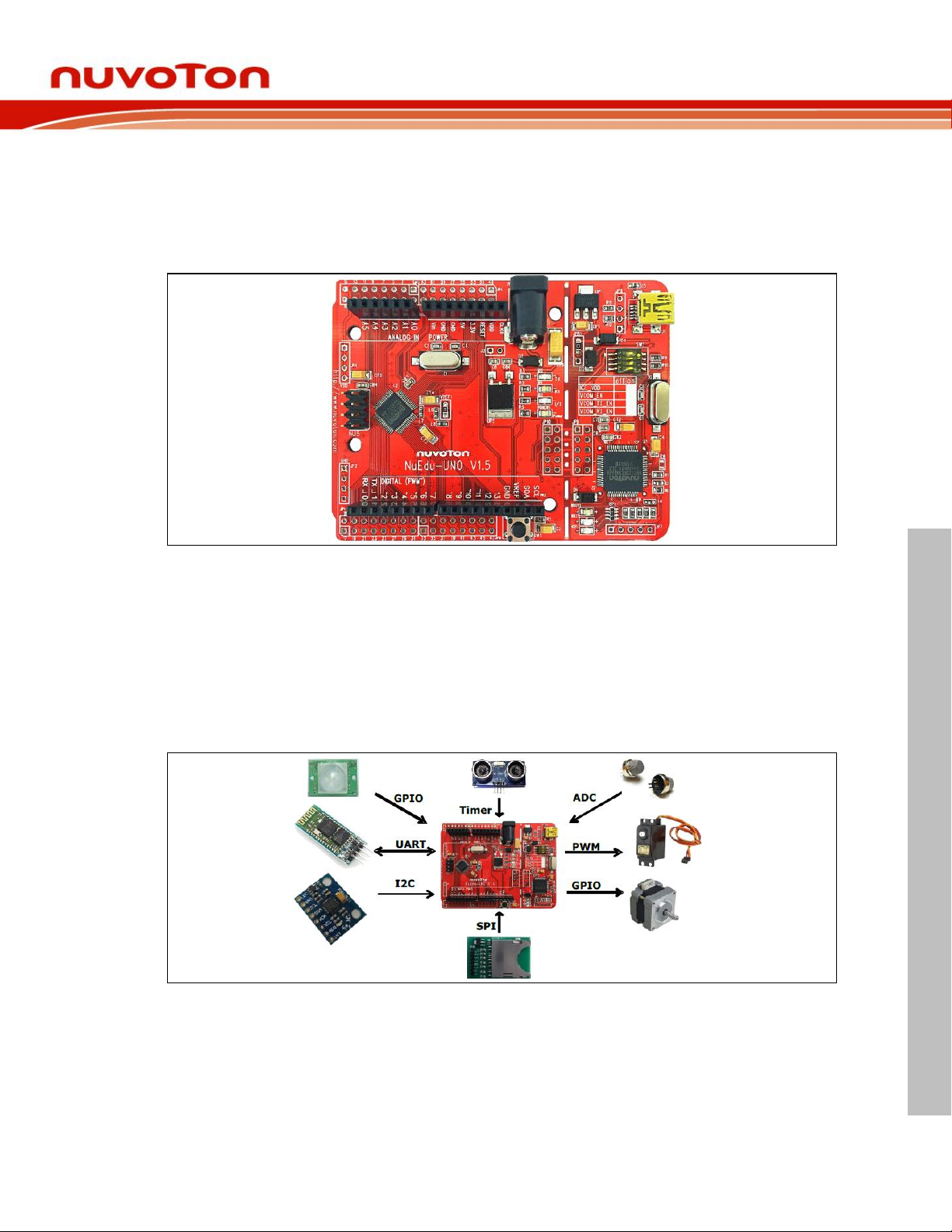
Figure 1-1 NuMaker UNO Board
The NuMaker UNO is a specific development tool for NuMicro® NUC131 series by which users
can develop and verify the application program easily. Its purpose is to provide a platform for
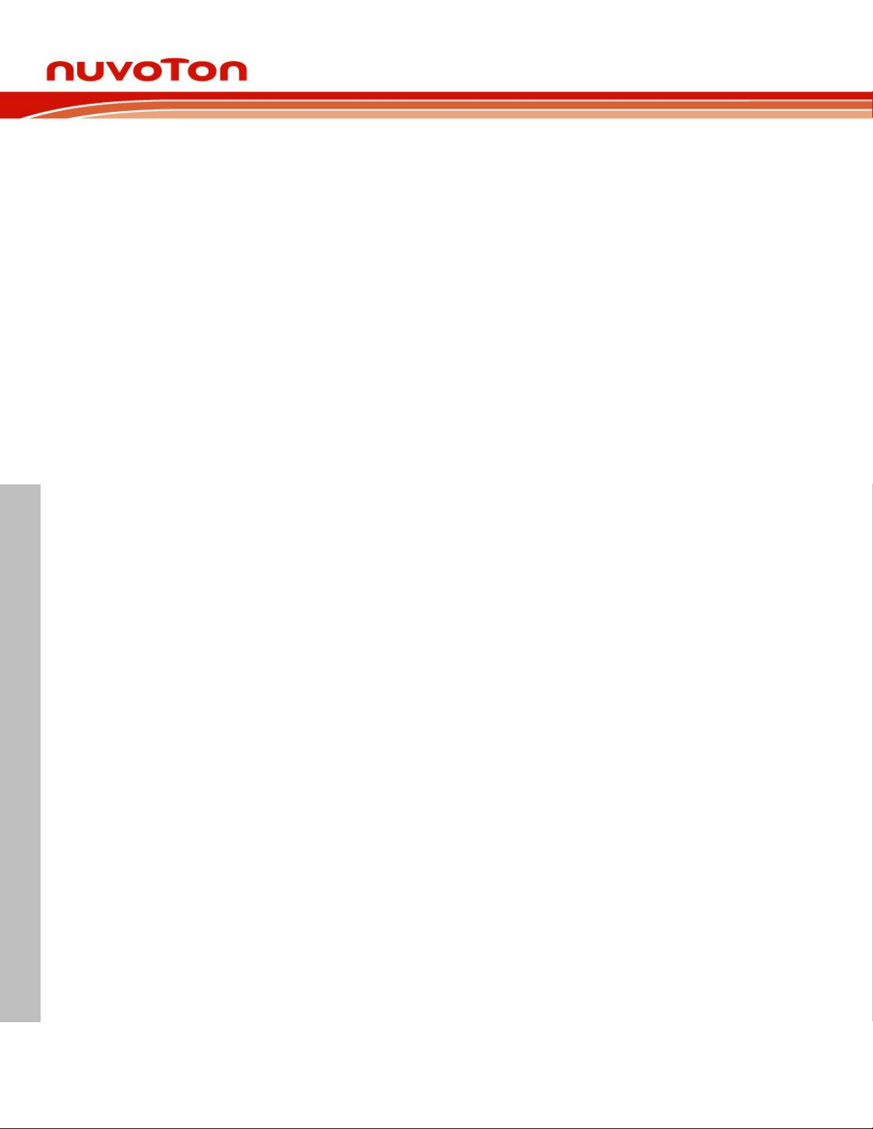
development and learning. With ADC, PWM, I²C, SPI, UART and other peripheral functions, user
can set different functions on the NuMaker UNO development kit, or increase the peripheral
functions according to the user needs on the development kit. The NuMaker UNO includes two
portions: NuMaker UNO (an evaluation board) and Nu-Link-Me (Debug Adaptor). With the
NuMaker UNO, users do not need additional ICE or debug equipment.
Figure 1-2 NuMaker UNO Board with Different Add-ons
The NuMaker UNO is pin to pin compatible with Arduino UNO board.
Digital pins provide UART, I2C, LED, INT, and 10-channels PWM. In addition, the extended pins
of MCU NUC131SD2AE provide 24-channels PWM and 6-channels UART. Clock Output (CLKO)
is also available on extra pin.
Aug 20, 2018 Page 3 of 43 Rev 1.02
Page 4
NUMAKER UNO USER MANUAL
2 FEATURES
The NuMaker UNO development board provides the following features:
Wide range of development tools for Learning/applications/debug
Portable package development and debugging tools
Rich MCU peripheral functions, such as ADC, PWM, I²C, SPI, and UART
Able to connect to different application modules due to high scalability
Supports pin to pin compatible with Arduino UNO revision 3
Supports USB virtual serial port (VCOM)
Supported by a wide choice of Integrated Development Environments (IDEs) including
Arduino IDE, IAR EWARM and Keil RVMDK IDE
Extension resources:
NuMicro® Morpho extension pin headers for full access to all MCU NUC131 I/O
On-board Nu-Link debugger/programmer with SWD connector
NuMaker UNO
Flexible board power supply:
USB VBUS (jumper JPR1 can be used to select 5V or 3.3V)
External VIN (7V ~ 12V) supply voltage from transformer converted into 5V
External 2.5 ~ 5.5V supply voltage from other power source input to VDD pin
LEDs Status
Power, TX, RX, ICE and user status
One push button: RESET
Aug 20, 2018 Page 4 of 43 Rev 1.02
Page 5
NuMaker UNO
NUMAKER UNO USER MANUAL
3 INTRODUCTION TO NUMAKER UNO DEVELOPMENT BOARD
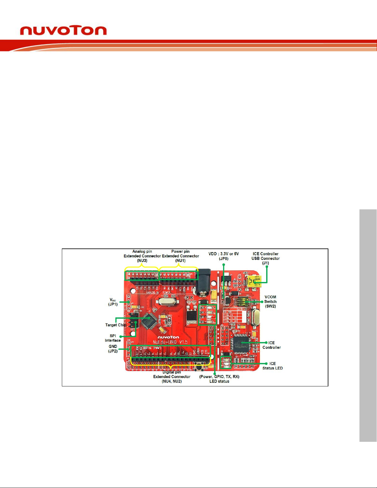
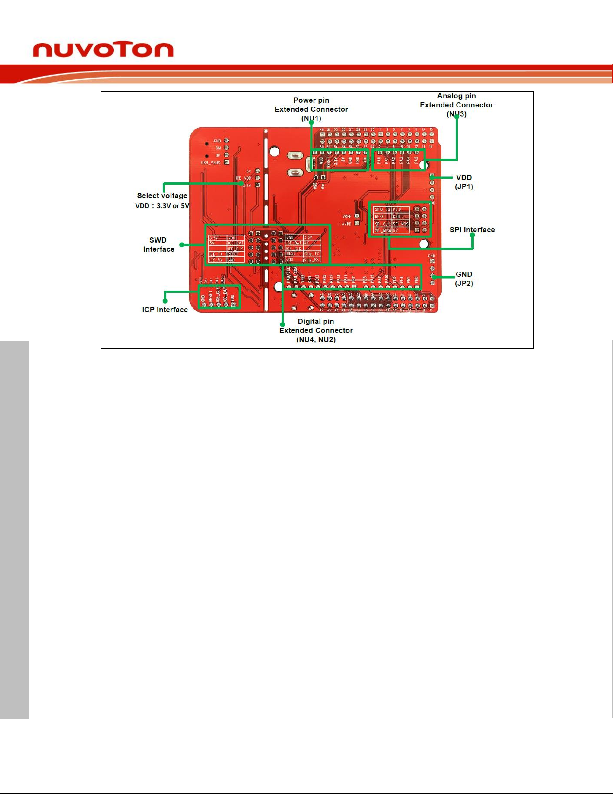
Figure 3-1 and Figure 3-2 show the NuMaker UNO development board, in which the left portion is
called NuMaker UNO target board and the right portion is Debug Adaptor called Nu-Link-Me.
The NuMaker UNO is similar to other development boards. Users can use it to develop and verify
applications to emulate the real behavior. NuMaker UNO can be a real system controller to design
user’s target system. NuMaker UNO is pin to pin compatible with Arduino UNO revision 3. The left
portion is NuMaker UNO target board where the NUC131 series MCU is mounted on. The
NUC131 series provides 24-ch PWM as well as 6-ch UART, and commonly used peripherals
such as Timer, WDT, SPI, I2C and ADC. The NUC131 series also provides CAN communication
interface.
The right portion is the debug adaptor called Nu-Link-Me which connects the USB port from PC to
user’s target system (via the Serial Wired Debug port) and allows users to program and debug
embedded programs on the target hardware. In addition to loading external application, it also
provides a virtual serial port (VCOM) functions. The debug messages through user-friendly NuLink–Me is displayed on the computer screen. For detailed description, please refer to section
3.1.2. The NuMaker UNO supports Arduino IDE, Keil, and IAR. For detailed installation and setup,
please refer to section 4.1.
The NuMaker UNO development board provides the Arduino pin-out definition and extended
connectors for each pin from the NUC131SD2AE MCU. It can be used to connect the application
circuit board. The target board also supports a wide range of power supplies, such as from ICE,
VDD & GND (JP1 & JP2) or from 7V ~ 12V transformer. LED status is for power, I/O, TX, RX and
ICE, as shown in Figure 3-1.
Figure 3-1 NuMaker UNO Development Board – Upper Side
Aug 20, 2018 Page 5 of 43 Rev 1.02
Page 6
NuMaker UNO
NUMAKER UNO USER MANUAL
Figure 3-2 NuMaker UNO Development Board – Bottom Side
Aug 20, 2018 Page 6 of 43 Rev 1.02
Page 7
NUMAKER UNO USER MANUAL
3.1 NuMaker UNO Jumper Description
Model
JPR1
(Selection Voltage)
JP1
(VDD Provided Voltage)
MCU Voltage
USB
Select 5V or 3.3V (Default is 5V)
USB, target board will be able to get the
supply voltage.
(SW2 pin1 need on)
DC 5V or 3.3V
Other power for VDD pin
X
External power supply DC 2.5 V ~ 5.5 V.
Voltage by JP1
input
Transformer
X
Transformer DC 7 V ~ 12 V, after pass
the step-down circuit, it provides 5V
supply to target chip
(J2 need short)
DC 5V
Switch Pin
Number
Function Name
UART0 Mode
VCOM Mode
1
ICE_VCC
On
On 2 VCOM_En
Off
On 3 VCOM_TX
Off
On 4 VCOM_RX
Off
On
3.1.1 Power Settings
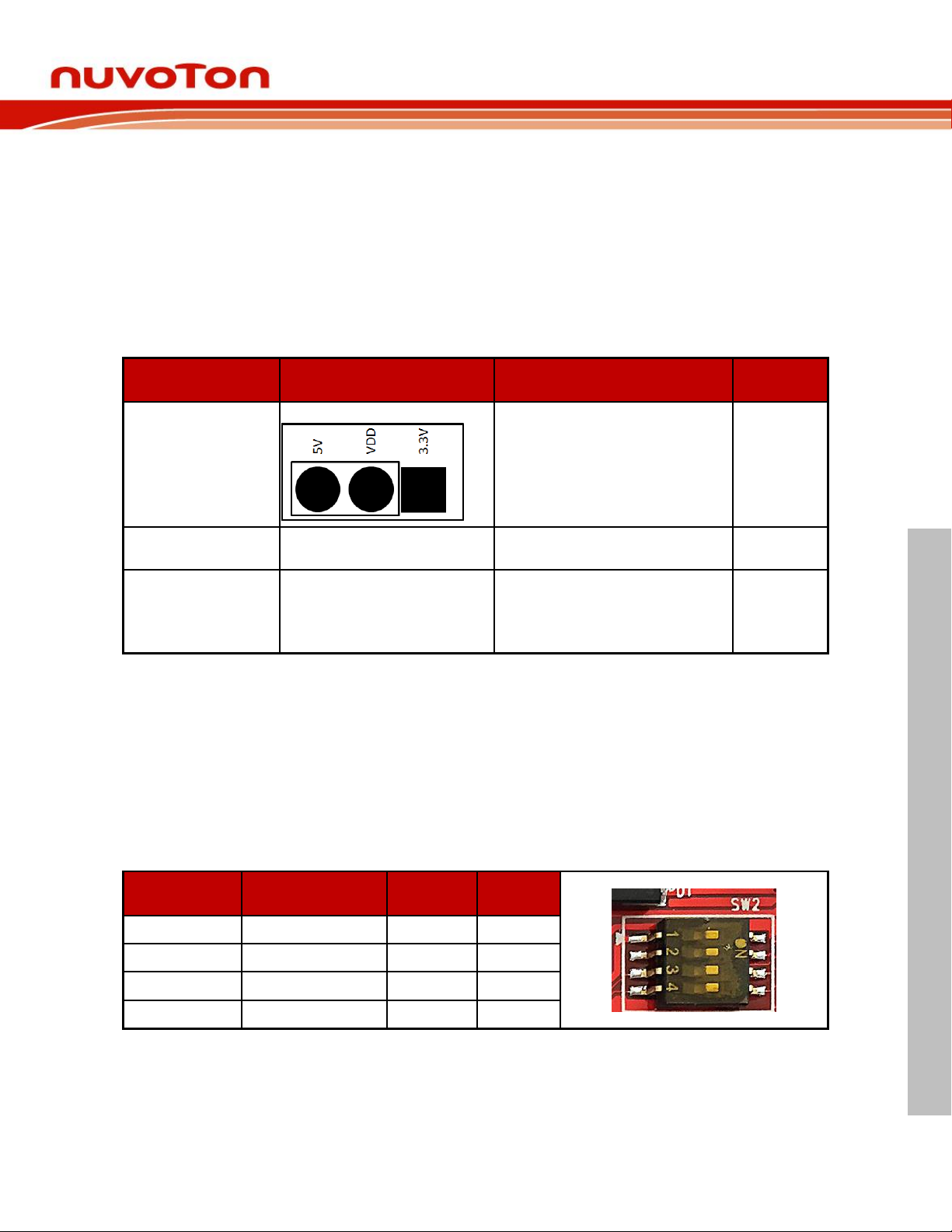
There are three methods to use the NuMaker UNO board to provide power to VDD. The first
method is through the Nu-Link-Me USB interface. This power will go through LDO voltage
regulator to 3.3V, JPR1 can be used to adjust VDD power to 5V or 3.3V. The second method is
through the JP1 on development board to VDD by DC 2.5V ~ 5.5V power supply. The third
method is through transformer (7V ~ 12V) and then the voltage is converted into 5V through
the step-down circuit. Please refer to the table below.
NuMaker UNO
Table 3-1 Power Settings
3.1.2 USB Virtual COM Function Setting
SW2: Open the Virtual COM mode for the debug message and supply power to NuMaker
UNO.
The Virtual COM function can be used for Arduino IDE, Keil and IAR. To enable VCOM
function on Nu-Link Me, turn on all SW2 pins. To enable the UART0 function, turn off pin 2 ~
pin 4 on SW2. Please refer to the table below.
Table 3-2 USB VCOM Setting (Default as VCOM Mode)
Aug 20, 2018 Page 7 of 43 Rev 1.02
Page 8
NUMAKER UNO USER MANUAL
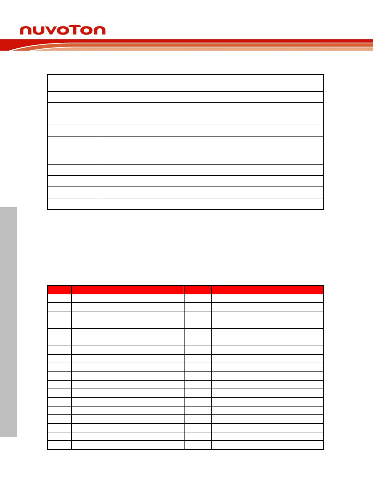
3.1.3 Header Description
JP1
V
DD
connector on NuMaker UNO, can be accessed by an external power supply DC 2.5V ~ 5.5V, in
order to provide NuMaker UNO power supply
JP2
GND connector on NuMaker UNO, can be accessed by external power supply GND
J1
Mini USB connector on Nu-Link-Me connected to the PC USB port
SW2
Pin 1 is ICE V
DD
connected to target chip VDD
CON1
7 V ~ 12 V transformer
J2
Power JACK is connected to VDD transformer, after the step-down circuit then to provide VDD power
supply to target Chip
SW1
Reset button on NuMaker UNO
JP10
Connector on target board (NuMaker UNO) for connecting to Nuvoton ICE adaptor (Nu-Link-Me)
JP9
Connector on ICE adaptor (Nu-Link-Me) for connecting to the target board (NuMaker UNO)
JP3 ~ JP6
Show all NUC131SD2AE MCU pin-out on NuMaker UNO
X
Unused
Pin No
Pin Name
Pin No
Pin Name
01
PB.14,INT0
33
PC.11,PWM1_BRAKE1
02
PB.13
34
PC.10,PWM1_BRAKE0
03
PB.12,CLKO,BPWM1_CH3
35
PC.9,PWM0_BRAKE1
04
PF.5,I2C0_SCL,PWM1_CH5
36
PC.8,PWM0_BRAKE0
05
PF.4,I2C0_SDA,PWM1_CH4
37
PA.15,PWM0_CH3
06
PA.11,I2C1_SCL,PWM1_CH3
38
PA.14,PWM0_CH2
07
PA.10,I2C1_SDA,PWM1_CH2
39
PA.13,PWM0_CH1,UART5_TXD
08
PA.9,I2C0_SCL,UART1_nCTS
40
PA.12,PWM0_CH0,UART5_RXD
09
PA.8,I2C0_SDA,UART1_nRTS
41
PF.7,ICE_DAT
10
PB.4,UART1_RXD
42
PF.6,ICE_CLK
11
PB.5,UART1_TXD
43
AVSS
12
PB.6,UART1_nRTS
44
PA.0,PWM0_CH4,ADC0,I2C1_SCL,UART5_TXD
13
PB.7,UART1_nCTS
45
PA.1,PWM0_CH5,ADC1,I2C1_SDA,UART5_RXD
14
LDO_CAP
46
PA.2,PWM1_CH0,ADC2,UART3_TXD
15
VDD
47
PA.3,PWM1_CH1,ADC3,UART3_RXD
16
VSS
48
PA.4,ADC4
17
PB.0,UART0_RXD
49
PA.5,UART3_RXD,ADC5
18
PB.1,UART0_TXD
50
PA.6,UART3_TXD,ADC6
NuMaker UNO
Table 3-3 Header Description
Note: When using the transformer power supply, please turn off all the SW2 pins.
3.2 Pin Assignment for NUC131SD2AE Extended Connectors
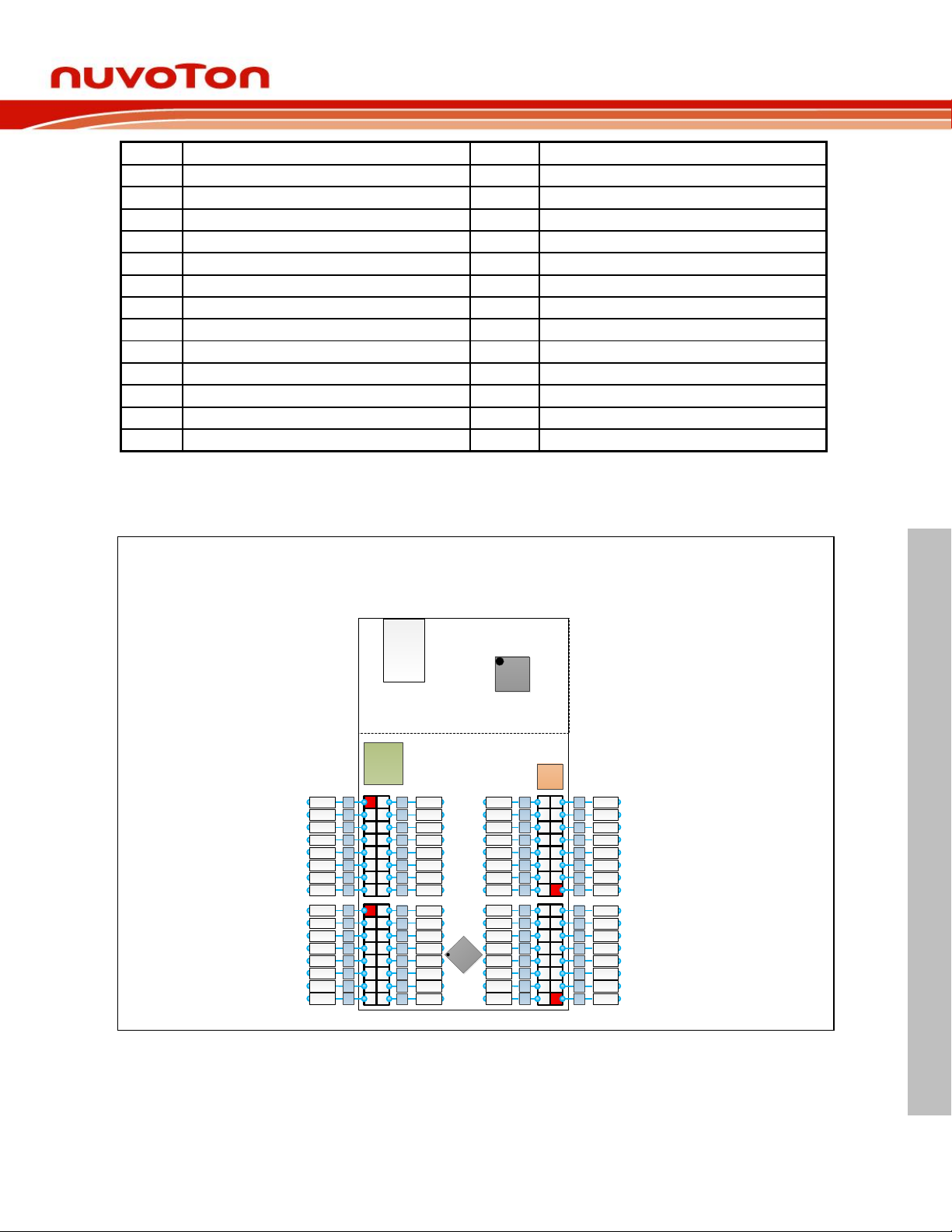
The NuMaker UNO provides the NUC131SD2AE target chip on board and the NUC131SD2AE
extended connectors (JP3, JP4, JP5 and JP6) for LQFP64-pin. Table 3-4 shows the pin
assignment for NUC131SD2AE.
Aug 20, 2018 Page 8 of 43 Rev 1.02
Page 9
NUMAKER UNO USER MANUAL
19
PB.2,UART0_nRTS,TM2_EXT,TM2,PWM1_BRAK
51
PA.7,Vref,ADC7
20
PB.3,UART0_nCTS,TM3_EXT,TM3,PWM1_BRAK
52
AVDD
21
PD.6,BPWM1_CH1,CAN0_RXD
53
PC.7,PWM0_BRAKE1,I2C0_SCL,UART4_RXD
22
PD.7,BPWM1_CH0,CAN0_TXD
54
PC.6,PWM0_BRAKE0,I2C0_SDA,UART4_TXD
23
PD.14,BPWM0_CH5,UART2_RXD
55
PC.15
24
PD.15,BPWM0_CH4,UART2_TXD
56
PC.14
25
PC.3,BPWM0_CH3,SPI0_MOSI0
57
PB.15, ,BPWM1_CH5TM0,TM0_EXT,INT1
26
PC.2,BPWM0_CH2,SPI0_MISO0
58
PF.0,XT1_OUT
27
PC.1,BPWM0_CH1,SPI0_CLK
59
PF.1,XT1_IN
28
PC.0,BPWM0_CH0,SPI0_SS0
60
nRESET
29
PE.5,PWM0_CH5,TM1_EXT,TM1
61
VSS
30
PB.11,TM3,PWM0_CH4
62
VDD
31
PB.10,TM2
63
PF.8, PWM1_CH4,CLKO
32
PB.9,TM1
64
PB.8,BPWM1_CH2,CLKO,TM0,STADC
Table 3-4 Pin Assignment for NUC131SD2AE
NuMaker UNO
USB
JACK
Power
Jack
NuLink-Me
PA.5 49
PA.7 51
53PC.7
55PC.15
57PB.15
59PF.1
61Vss
63PF.8
PB.12 3
PF.4 5
7PA.10
9PA.8
11PB.5
13PB.7
PA.650
64 PB.8
62 Vdd
nRESET
60
58 PF.0
56 PC.14
54 PC.6
52 AVdd
14
LDO_CAP
PB.612
10 PB.4
8 PA.9
6 PA.11
4 PF.5
PB.14 1
2 PB.13
15Vdd
16 Vss
PA.4 48
PA.2 46
44PA.0
42PF.6
40PA.12
38PA.14
36PC.8
34PC.10
PB.11 30
PC.0 28
26PC.2
24PD.15
22PD.7
20PB.3
PA.347
33 PC.11
35 PC.9
PA.1637
39 PA.13
41 PF.7
43 Avss
45 PA.1
19 PB.2
PD.621
23 PD.14
25 PC.3
27 PC.1
29 PE.5
PB.9 32
31 PB.10
18PB.1
17 PB.0
NUC131
SD2AE
Reset
3.3 NuMaker UNO NUC131SD2AE Extended Connectors Layout
NuMaker UNO
Aug 20, 2018 Page 9 of 43 Rev 1.02
Figure 3-3 NuMaker UNO NUC131SD2AE Extended Connectors Layout
Page 10
NUMAKER UNO USER MANUAL
Pin No
Pin Name
Pin No
Pin Name
Clock Output
1
CLKO
5
5V
Power
2
VCC 6 GND
3
RESET
7
GND
4
3.3V 8 Vin
Analog
1
A0 4 A3 2 A1 5 A4 3 A2 6 A5
Digital
0
PB.0/UART_RX0
9
PA.14/PWM0_CH2
1
PB.1/UART_TX0
10
PA.13/PWM0_CH1
2
PF.4/PWM1_CH4
11
PA.12/PWM0_CH0
3
PF.5/PWM1_CH5
12
PB.15/TM0/INT1
4
PA.10/PWM1_CH2
13
PB.13(LED)
5
PA.11/PWM1_CH3
VSS
VSS 6 PA.15/PWM0_CH3
VREF
VREF
7
PE.5/PWM0_CH5
I2C
PA.8/SDA
8
PB.11/PWM0_CH4
I2C
PA.9/SCL
SPI
Interface
1
PC.2/SPI0_MISO
5
RESET
2
VDD 6 GND 3 PC.1/SPI0_CLK
7
PC.0/SPI0_SS
4
PC.3/SPI0_MOSI
8
PB.9/TM1
3.4 Arduino UNO Pin Assignment for NuMaker UNO
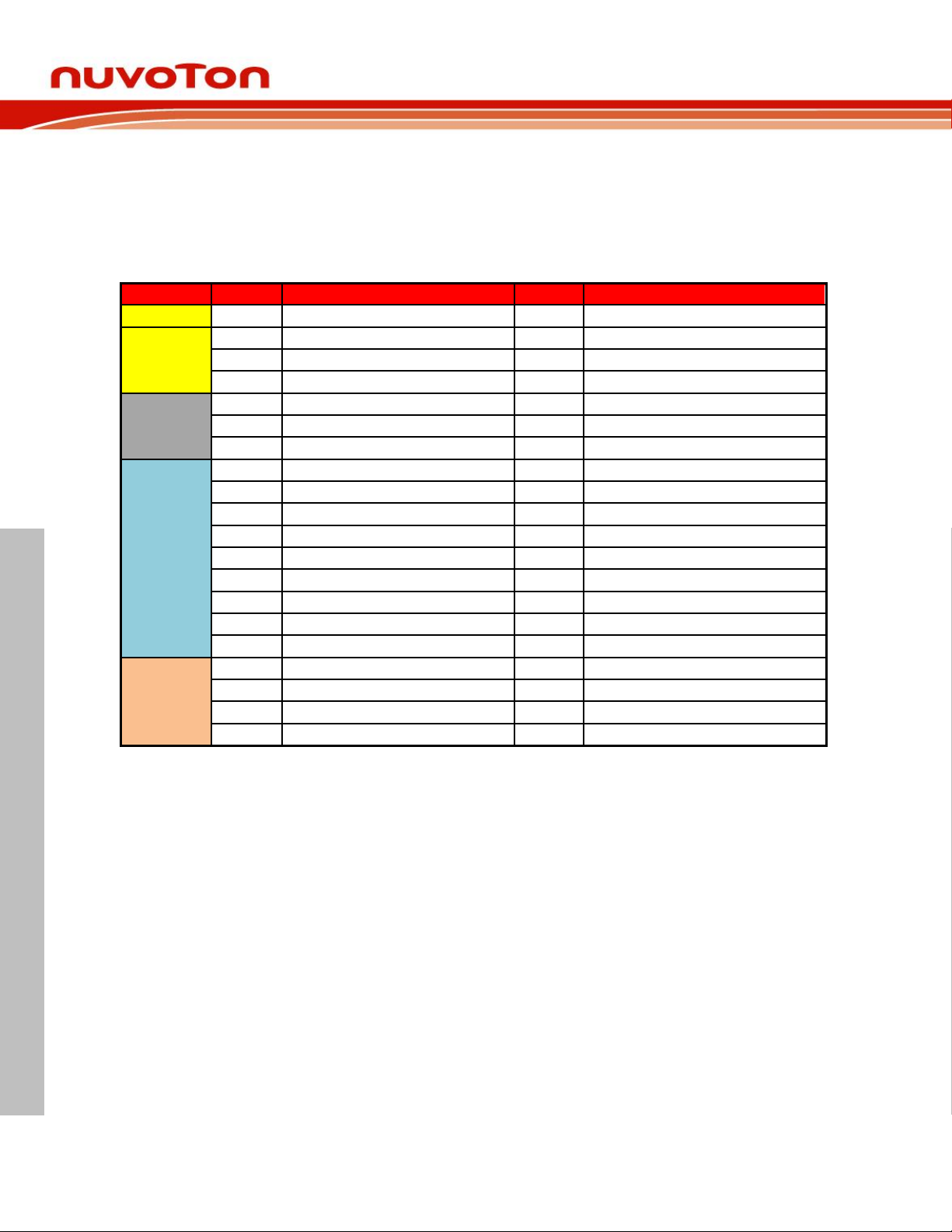
The NuMaker UNO provides the NUC131SD2AE target chip on board and the Arduino UNO
extended connectors (NU1, NU2, NU3, NU4 and NU5) for LQFP64-pin. Table 3-5 shows the
pin assignment for NuMaker UNO.
NuMaker UNO
Table 3-5 Pin Assignment for NuMaker UNO
Aug 20, 2018 Page 10 of 43 Rev 1.02
Page 11
NUMAKER UNO USER MANUAL
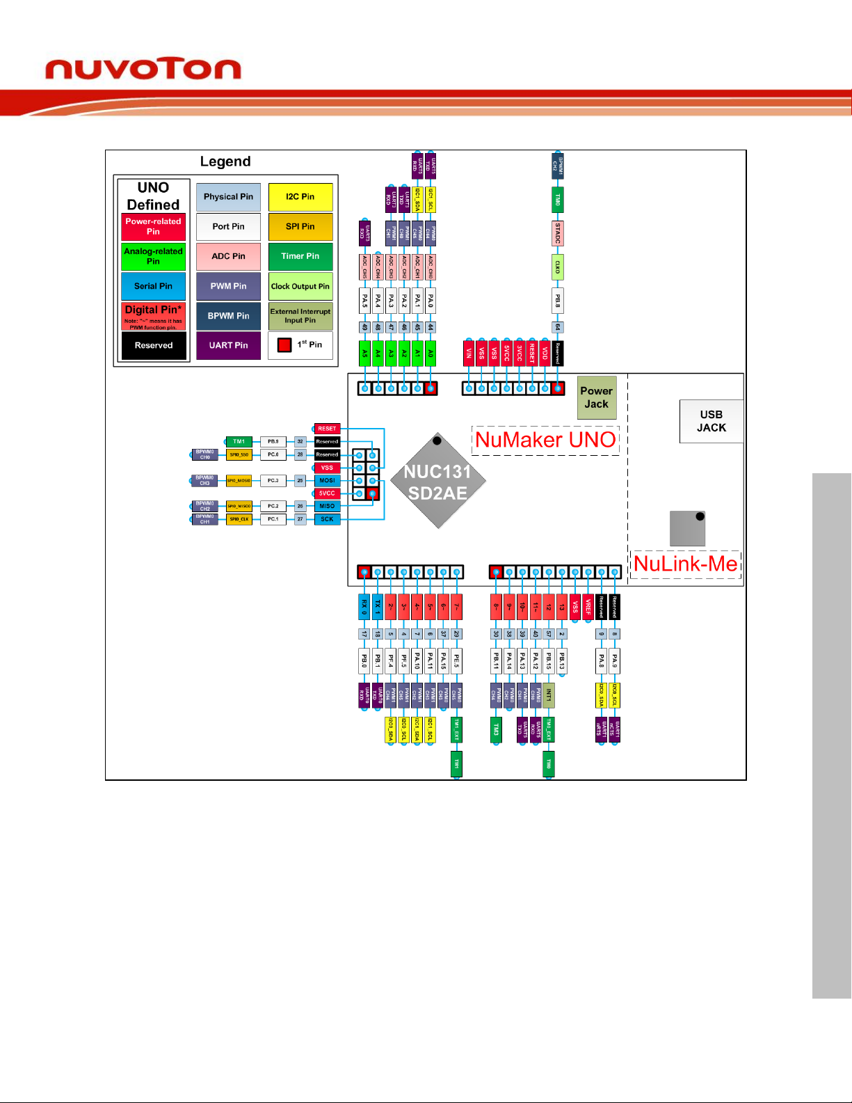
3.5 NuMaker UNO Arduino Layout
NuMaker UNO
Figure 3-4 NuMaker UNO Pin Design for Arduino
Aug 20, 2018 Page 11 of 43 Rev 1.02
Page 12
NUMAKER UNO USER MANUAL
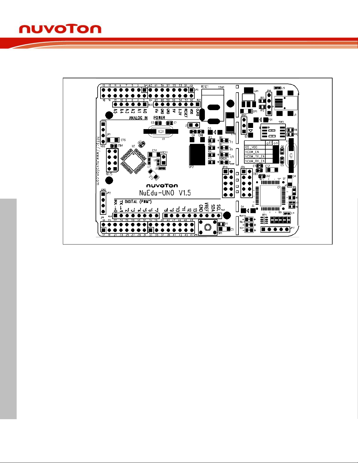
3.6 NuMaker UNO PCB Placement
NuMaker UNO
Figure 3-5 NuMaker UNO PCB Placement
Aug 20, 2018 Page 12 of 43 Rev 1.02
Page 13
NuMaker UNO
NUMAKER UNO USER MANUAL
4 DOWNLOADING AND INSTALLING ARDUINO IDE 1.8.5 AND NUMAKER
UNO SOFTWARE
4.1 Downloading and Installing Arduino IDE 1.8.5 Software
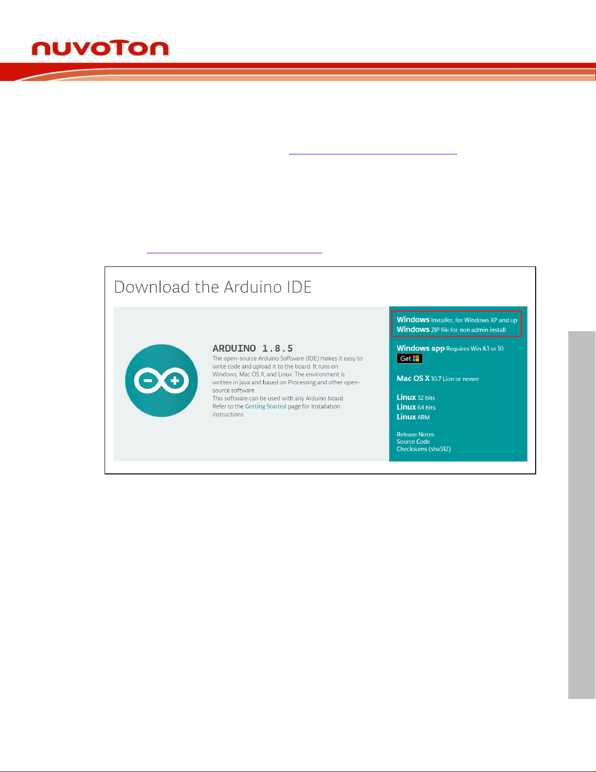
Please visit the Arduino official website (http://www.arduino.cc/en/Main/software) to download
and install the Arduino IDE 1.8.5. Currently it is recommended to install Arduino IDE 1.8.5 for
Windows version, since the other operating system has not been verified.
The Arduino IDE 1.8.5 installation steps are as follows:
4.1.1 Step 1: Download Arduino IDE 1.8.5 software
Visit https://www.arduino.cc/en/Main/Software, and download the latest Arduino.
Figure 4-1 Find and Click “previous version of the current release”
Aug 20, 2018 Page 13 of 43 Rev 1.02
Page 14
NUMAKER UNO USER MANUAL
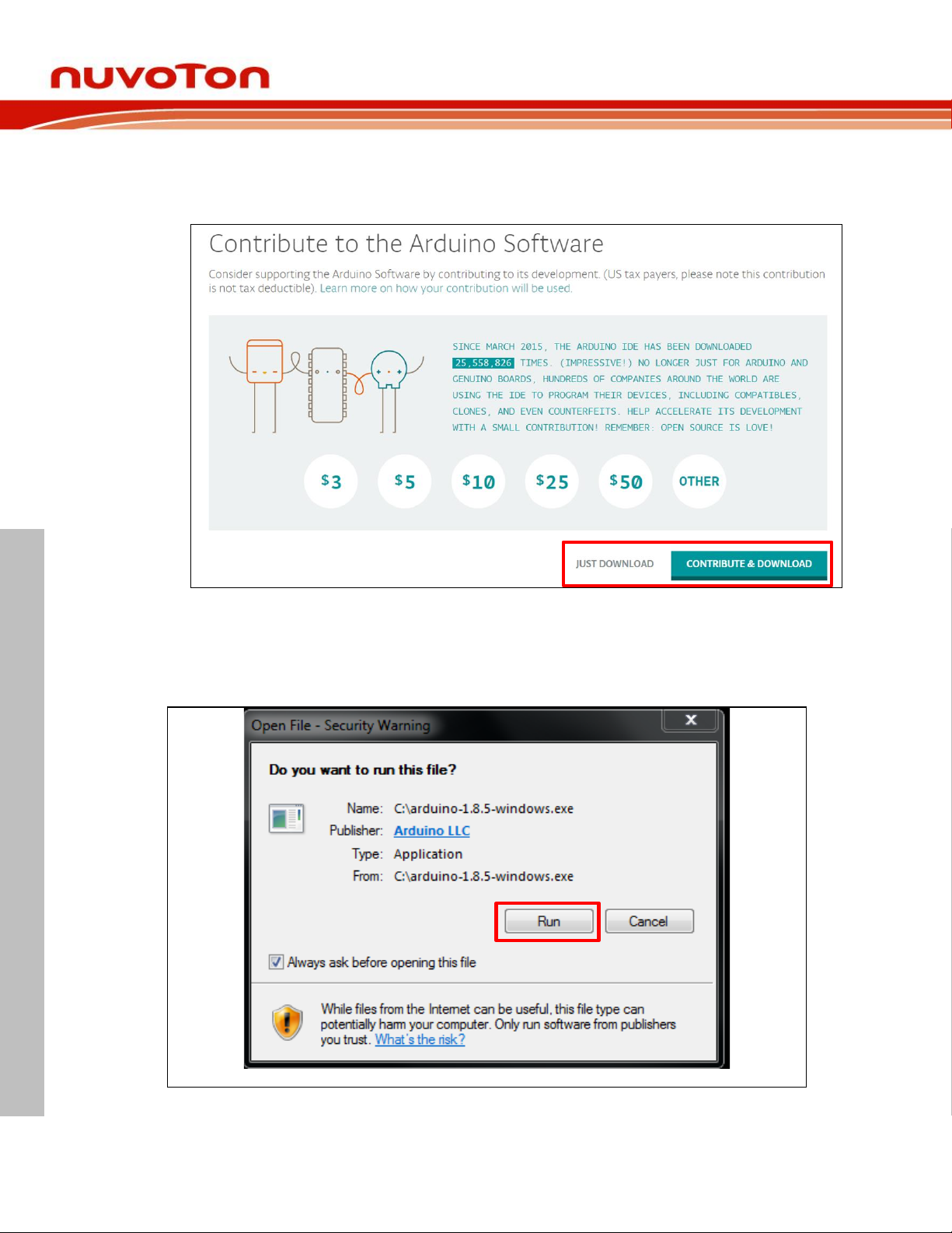
4.1.2 Step 2: Check if download file is version 1.8.5
Click on download.
NuMaker UNO
Figure 4-2 Find and Download Arduino 1.8.5
4.1.3 Step 4: Install the “Arduino-1.8.5-windows.exe” file
Double click on the “arduino-1.8.5-windows.exe” and click “Run”.
Figure 4-5 Install arduino-1.8.5-windows.exe Installation File
Aug 20, 2018 Page 14 of 43 Rev 1.02
Page 15
NUMAKER UNO USER MANUAL
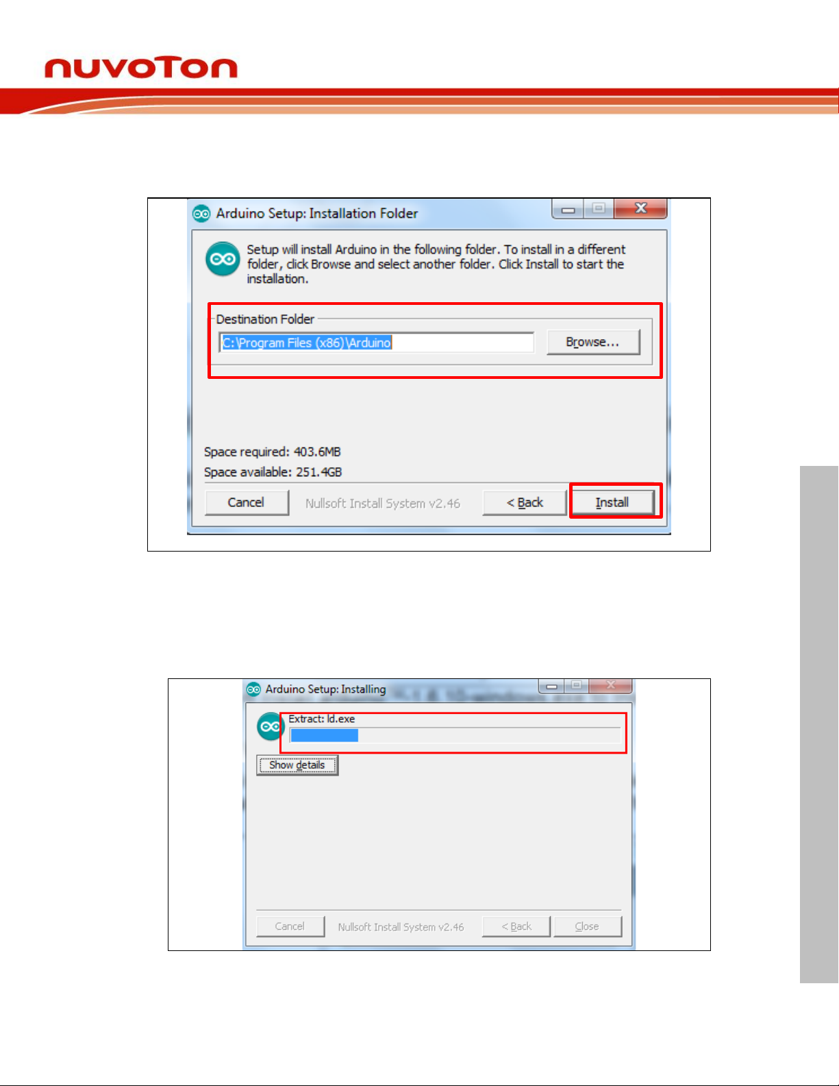
4.1.4 Step 5: Select the installation folder
Select the installation folder and click “Install”.
NuMaker UNO
Figure 4-6 Install arduino-1.8.5-windows.exe to Installation Folder
4.1.5 Step 6: Wait for the installation is complete
Wait the installation process until it is finished. It will take about 2 minutes to install arduino-
1.8.5-windows file to the installation folder.
Figure 4-7 Install arduino-1.8.5-windows to Installation Folder
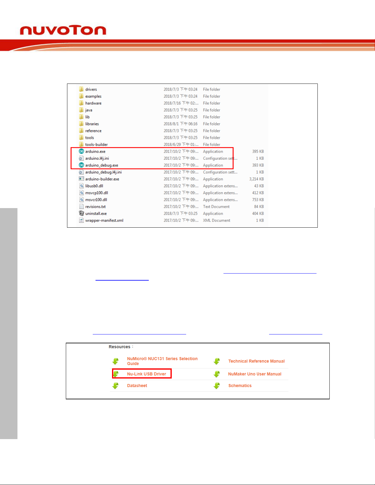
After installation is finished, two executable files can be found in the Arduino 1.8.5 installation
directory, including arduino.exe and arduino_debug.exe. Both files are able to start the Arduino
Aug 20, 2018 Page 15 of 43 Rev 1.02
Page 16
NuMaker UNO
NUMAKER UNO USER MANUAL
IDE program. As for the arduino_debug.exe, you can open the debug window. When the
program is executed or compiled, the debug window will open for users to check which part of
the problem occurs.
Figure 4-8 Arduino 1.8.5 Installation Directory
4.2 Installing Nu-Link USB Driver for Arduino IDE 1.8.5
Please visit the Nuvoton NuMaker UNO official website (www.nuvoton.com/NuMaker_UNO) to
download “Nu-Link USB Driver”.
Note: It is recommended to use Arduino IDE version 1.8.5.
The Nu-Link USB Driver installation steps are as follows:
4.2.1 Step 1: Download Nu-Link USB Driver
Visit www.nuvoton.com/NuMaker_UNO and find Resources. Click on “Nu-Link USB Driver”.
Figure 4-9 Find and Click Nu-Link USB Driver
Aug 20, 2018 Page 16 of 43 Rev 1.02
Page 17
NUMAKER UNO USER MANUAL
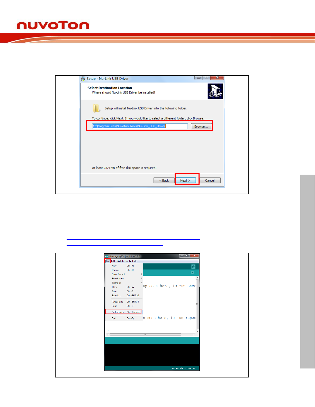
4.2.2 Step 2: Select the installation folder
Select the installation folder and click “Next” to install.
NuMaker UNO
Figure 4-10 Installing Nu-Link USB Driver
4.2.3 Step 3: Run Arduino IDE 1.8.5
Go to File → Preferences, enter the following URL to textbox of ‘Additional Board Manager
URLs’
https://raw.githubusercontent.com/OpenNuvoton/NuMakerUNO/master/package_nuvoton_index.json
Figure 4-11 Arduino IDE 1.8.5 Select File and Click Preferences
Aug 20, 2018 Page 17 of 43 Rev 1.02
Page 18
NuMaker UNO
NUMAKER UNO USER MANUAL
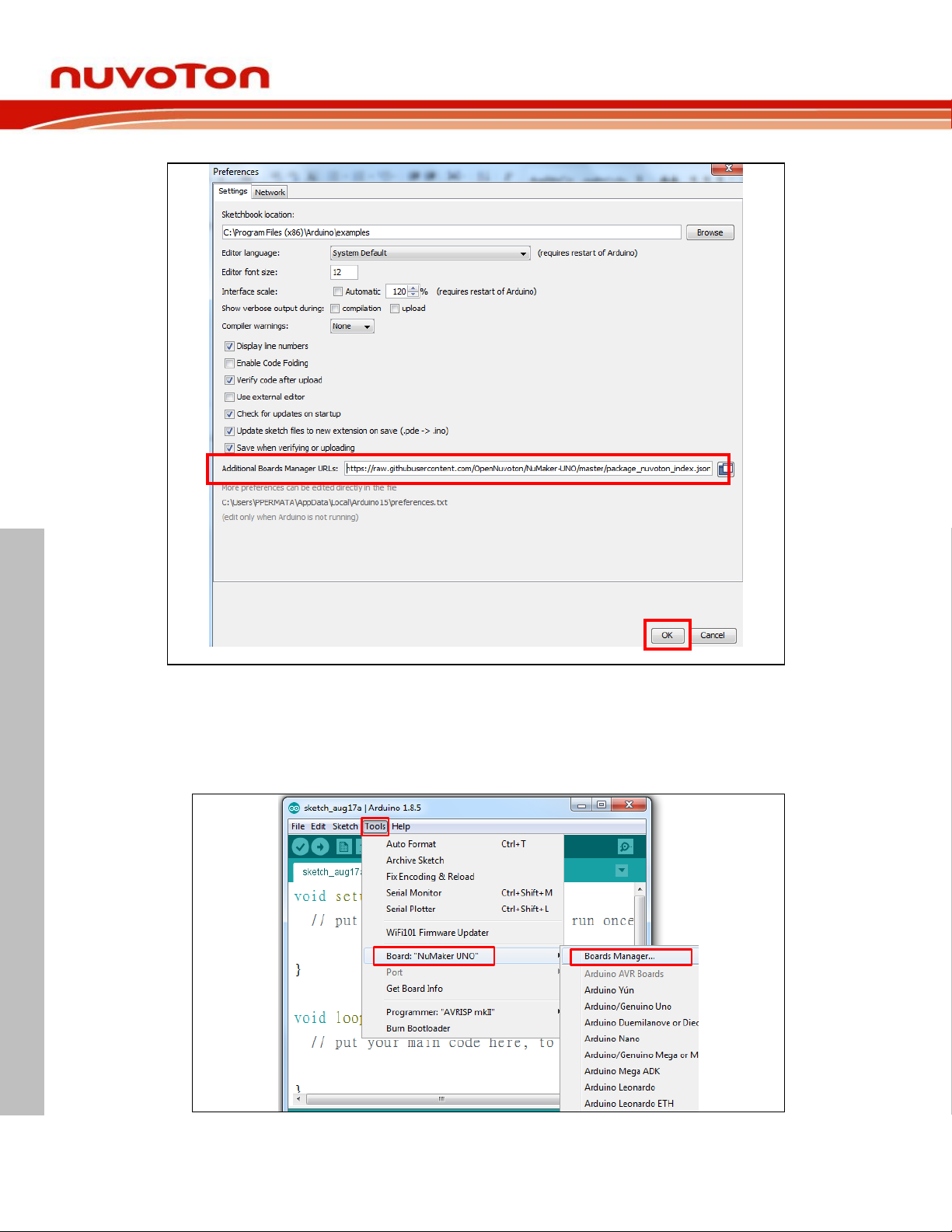
Figure 4-12 Enter the NuMaker UNO Board’s URL to ‘Additional Board Manager URLs’
4.2.4 Step 4: Install NuMaker UNO on Arduino IDE 1.8.5 Boards Manager
Go to Tools → Board → Boards Manager on Arduino IDE 1.8.5.
Figure 4-13 Click Boards Manager on Arduino IDE 1.8.5
Aug 20, 2018 Page 18 of 43 Rev 1.02
Page 19
NuMaker UNO
NUMAKER UNO USER MANUAL
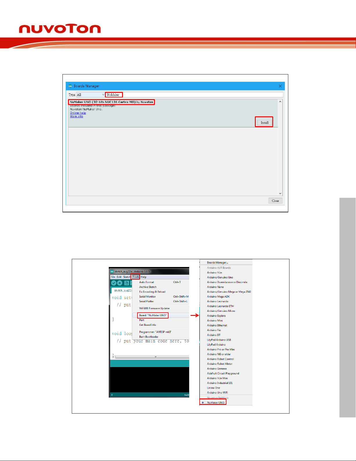
Search “MuMaker” and the NuMaker UNO will show up on the list. Select NuMaker UNO
and click install.
Figure 4-14 Select NuMaker UNO and Click Install
4.2.5 Step 5: Select NuMaker UNO on Arduino IDE 1.8.5 Board Selection
After the package download is finished, go to Tools → Board and select NuMaker UNO to
use it.
Figure 4-15 Select NuMaker UNO on Board Selection to Use It
Aug 20, 2018 Page 19 of 43 Rev 1.02
Page 20
NUMAKER UNO USER MANUAL
4.3 Hardware Setup
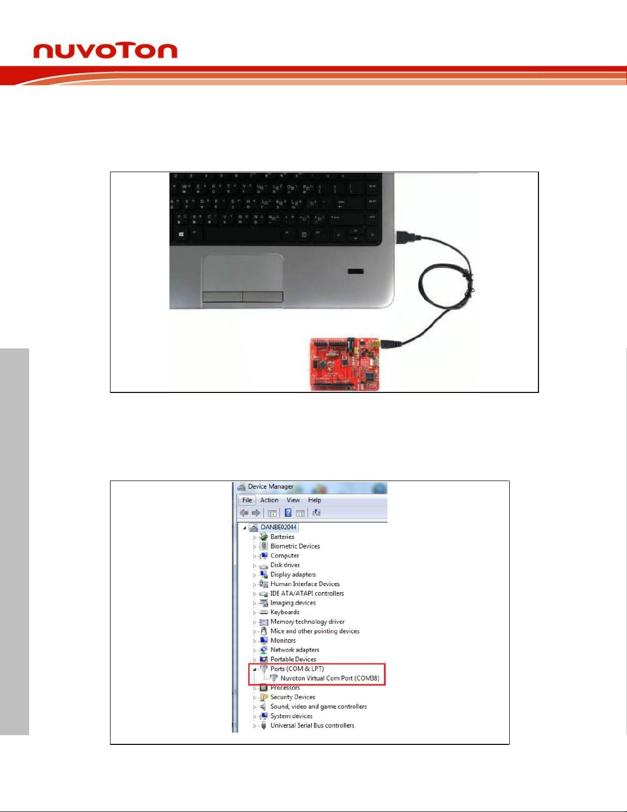
Hardware connections are shown in the figure below. Use a mini USB to connect to a
computer.
NuMaker UNO
Figure 4-16 NuMaker UNO Connected to Computer
4.4 Testing USB and VCOM Device in the Device Manager
Before connecting the NuMaker UNO development board to the computer, please enable SW2
of VCOM Function. All the SW2 pins shall be turned on. Please refer to section 3.1.2. Open the
device manager and check if the USB is detected. If it is not detected, please reinstall the NuLink USB Driver.
Figure 4-17 USB Device Detected by Device Manager
Aug 20, 2018 Page 20 of 43 Rev 1.02
Page 21
NUMAKER UNO USER MANUAL
5 STARTING TO USE NUMAKER UNO ON ARDUINO IDE 1.8.5
Switch Pin
Number
Function Name
UART0 Mode
VCOM Mode
1
ICE_VCC
On
On 2 VCOM_En
Off
On
3
VCOM_TX
Off
On
4
VCOM_RX
Off
On
5.1 Compiling and Executing Example Program
This example demonstrates how to download an application and debug using virtual serial port
on a NuMaker UNO board. When users install the Nu-Link USB Driver, the “NuMaker UNO” can
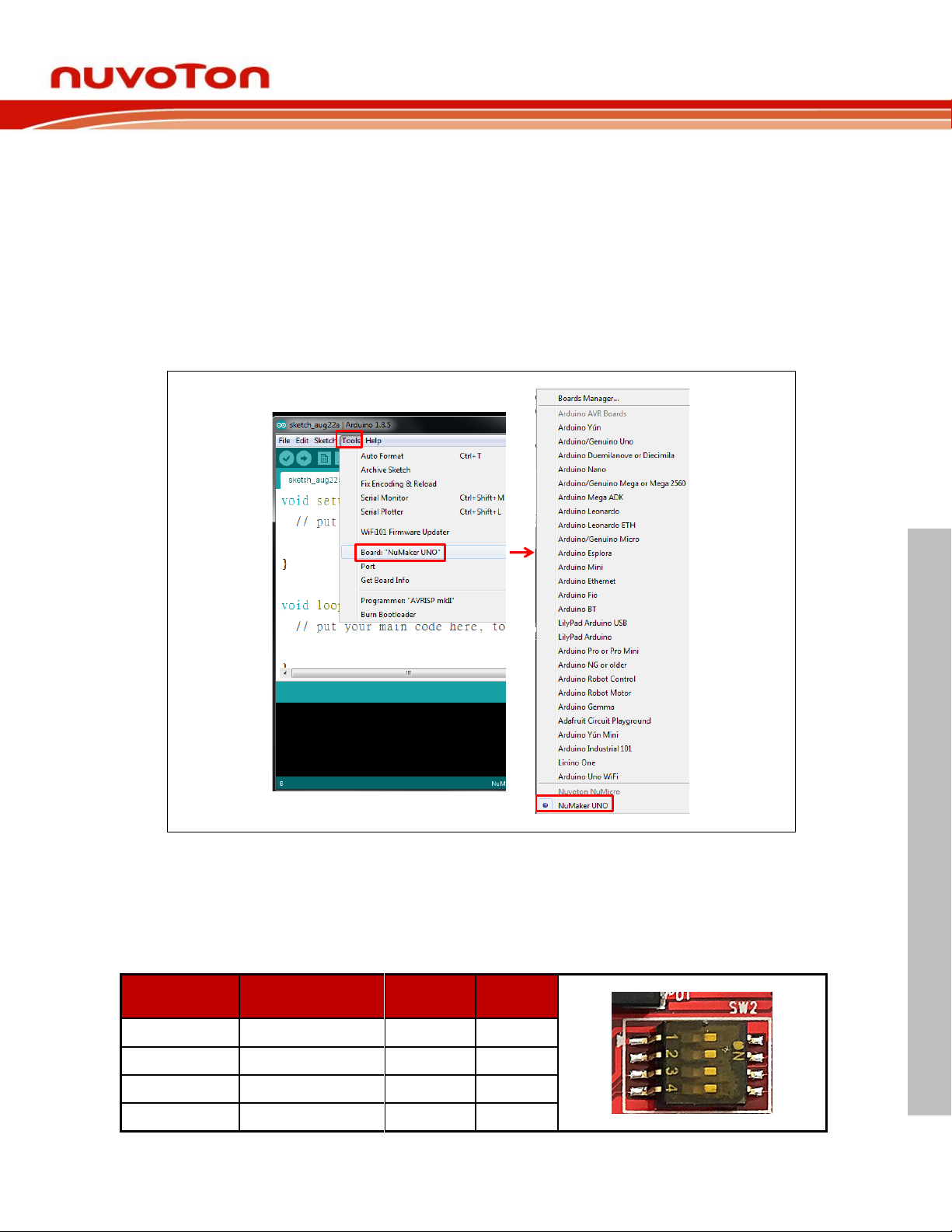
be found in Arduino IDE on Tools Board NuMaker UNO as shown in the figure below.
Note: Execute the “arduino_debug.exe” file in the installation path.
5.1.1 Step 1: Select the NuMaker UNO Board
NuMaker UNO
Figure 5-1 NuMaker UNO Board Selection on Arduino IDE
5.1.2 Step 2: Open virtual serial modes and select Debug Serial Port
SW2: Supply power to NuMaker UNO. Before NuMaker UNO is connected to PC, all the SW2
pins shall be turned on. To activate UART0 function, SW2 pin2 ~ pin4 shall be turned off.
Table 5-1 SW2 Mode Setting (Default as VCOM Mode)
Aug 20, 2018 Page 21 of 43 Rev 1.02
Page 22
NuMaker UNO
NUMAKER UNO USER MANUAL
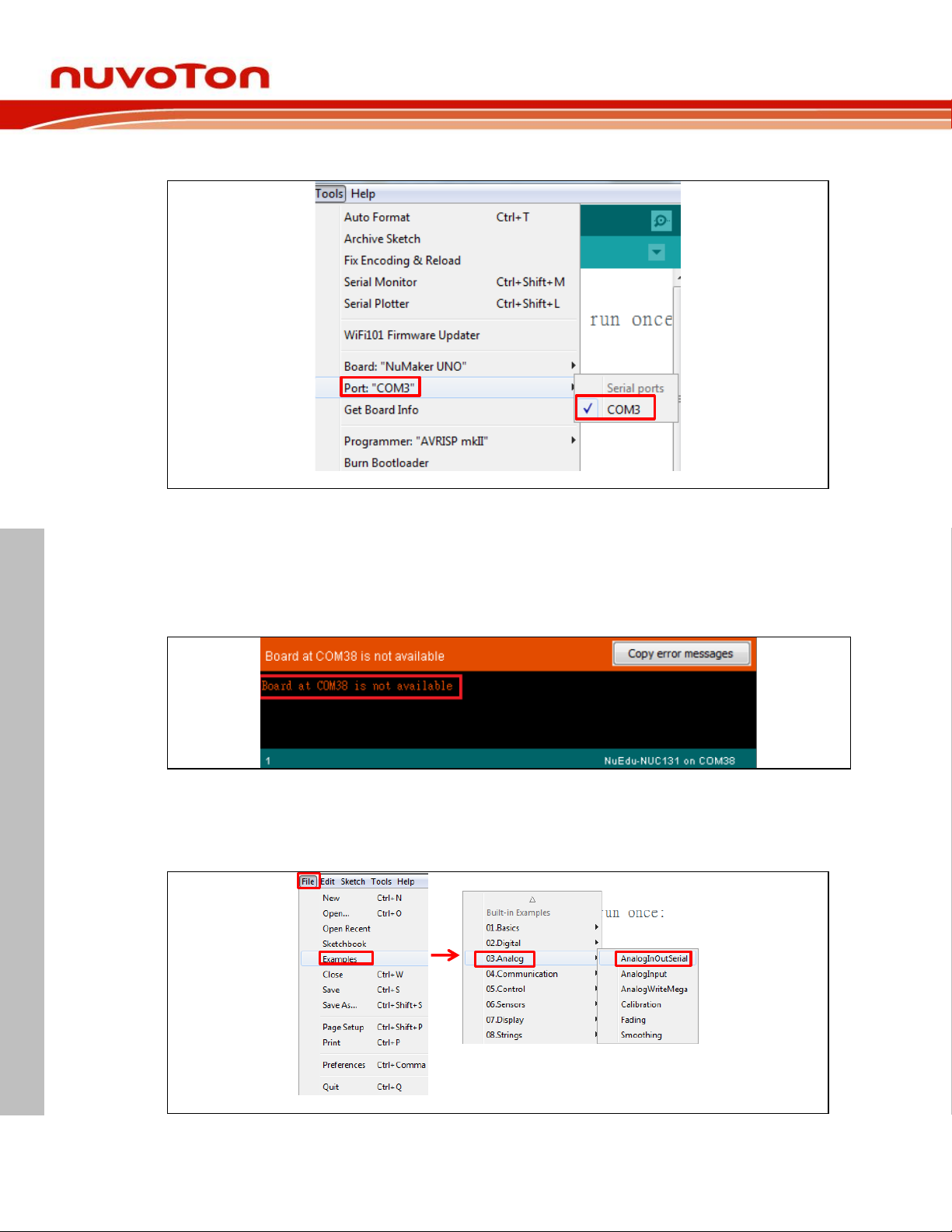
After SW2 setting is completed, you will be able to see the serial COM port number.
Figure 5-2 Select NuMaker-UNO Serial COM Port
Note 1: If the SW2 pin 2 of VCOM function is not enabled, Tools Port will become gray
(disabled), unless the board is re-connected to the computer. However, before re-connecting
to PC, you must open the VCOM function.
Note 2: If the serial port number is not selected, you will not be able to use the serial monitor.
Figure 5-3 COM port Not Detected and Unable to Use Serial Monitor
5.1.3 Step 3: Open the sample code
Open the sample code through File Examples 03.Analog AnalogInOutSerial.
Figure 5-4 Open the Sample Code
Aug 20, 2018 Page 22 of 43 Rev 1.02
Page 23
NUMAKER UNO USER MANUAL
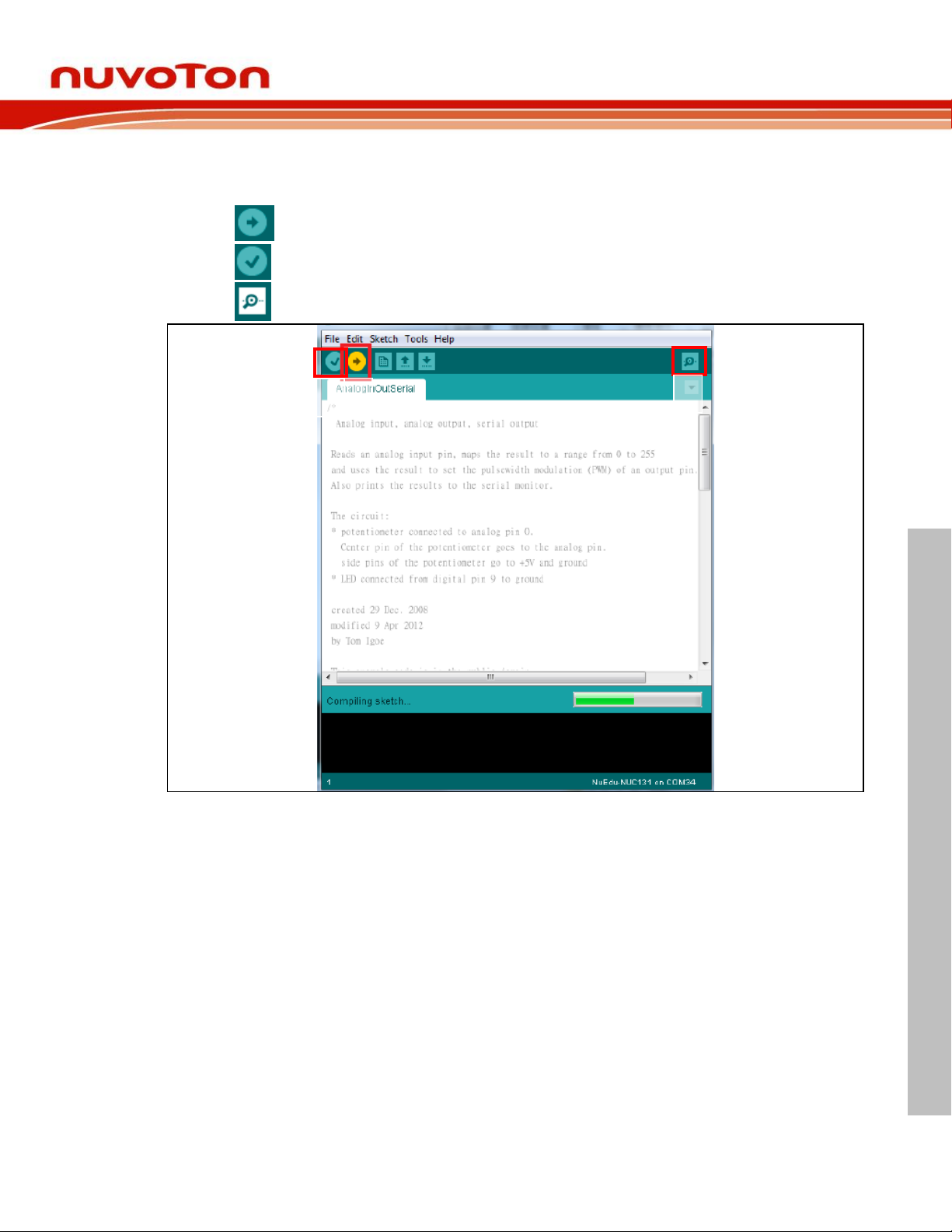
5.1.4 Step 4: Download the sample code
1 2 3
Use the Upload button to compile and load code to target board or use the Verify button to
compile code.
1. Upload: This button can compile and load code to a target board.
2. Verify: This button can compile code.
3. Serial Monitor: This button can open the serial monitor.
NuMaker UNO
Figure 5-5 Sample Program Compiled and Loaded
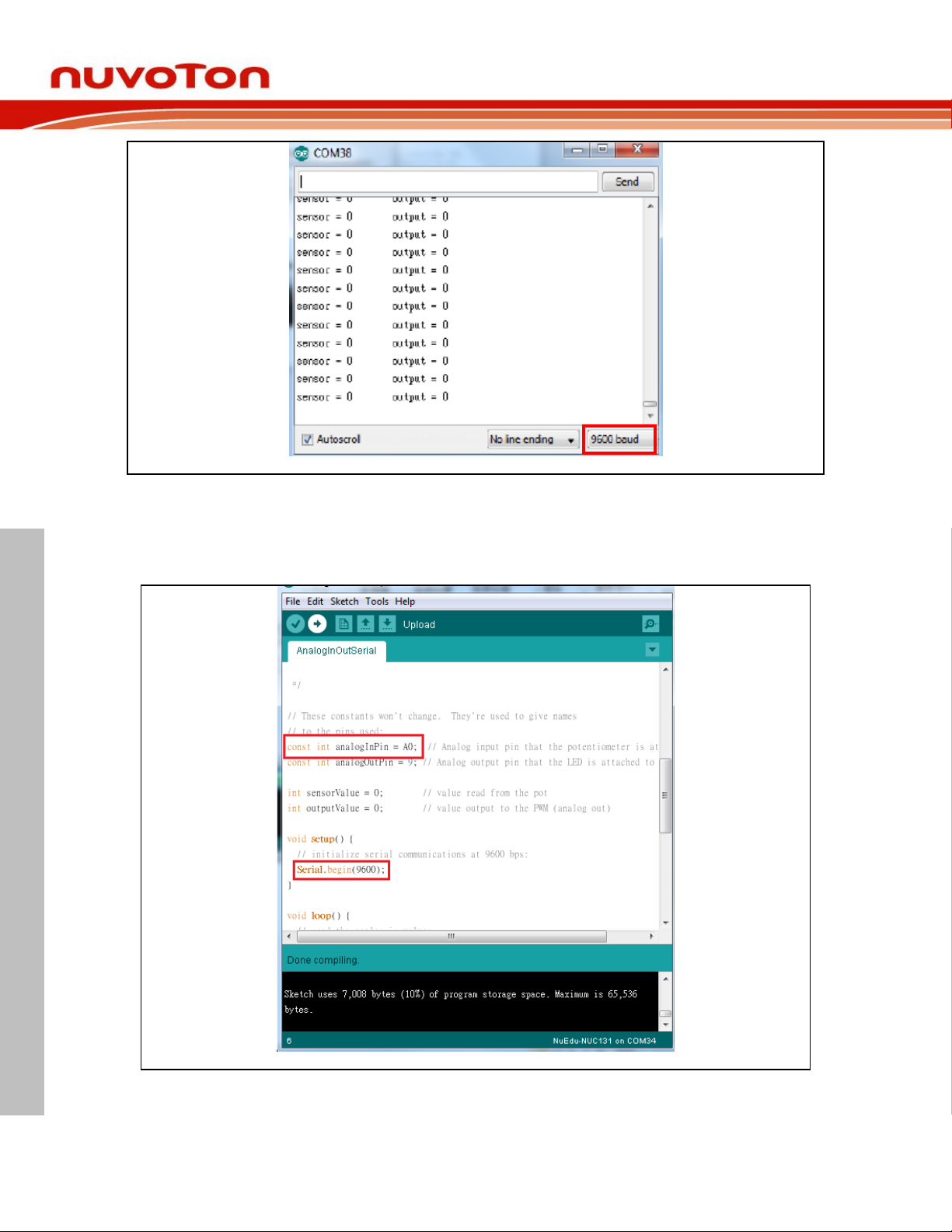
5.1.5 Step 5: Check the Correctness of the VCOM Baud Rate
User needs to check if the virtual serial port baud rate setting is the same as the program
setting. When the program is set to 9600, the virtual serial port monitor will be set as 9600.
Aug 20, 2018 Page 23 of 43 Rev 1.02
Page 24
NuMaker UNO
NUMAKER UNO USER MANUAL
Figure 5-6 Serial Monitor
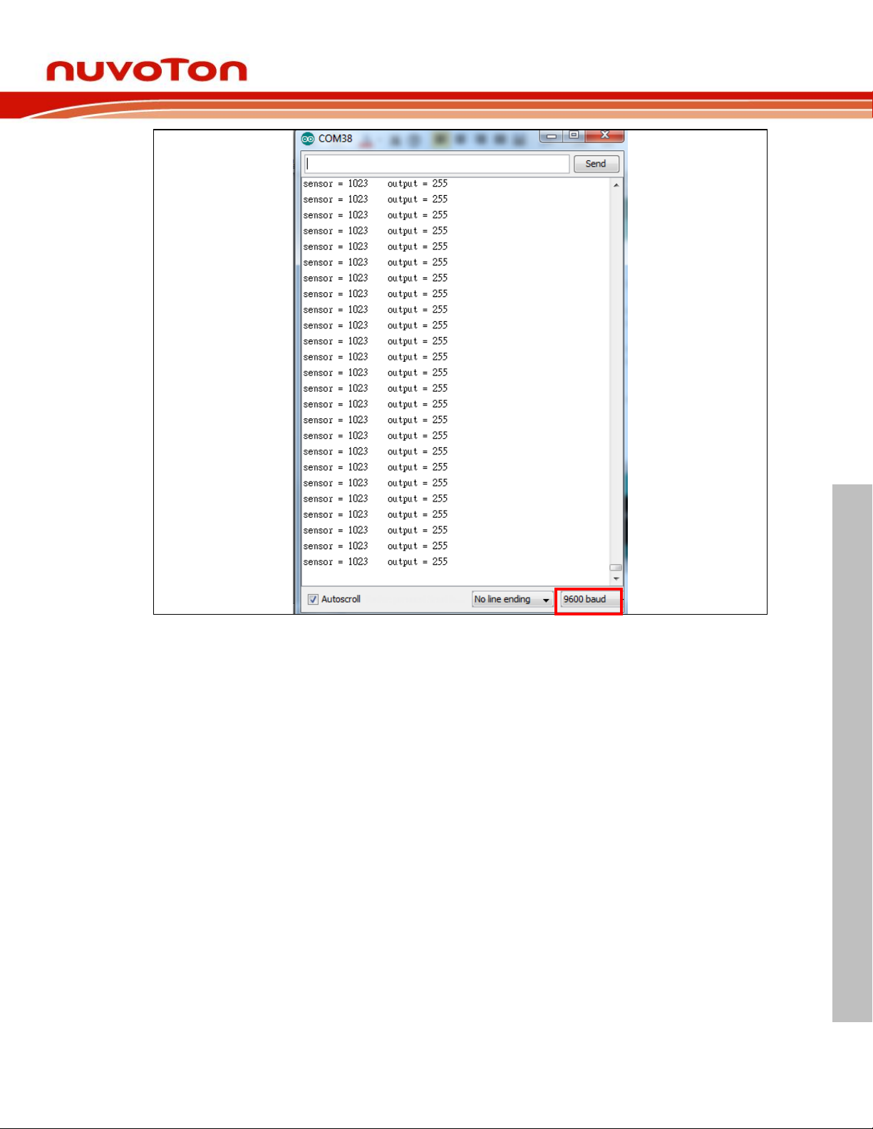
This example uses ADC0 to perform ADC conversion into a digital value which is then displayed
by the virtual serial port out. To set a COM port baud rate and then display the virtual serial
conversion results, use the ADC0 pin connected to VDD or VSS. Then, whether the ADC
conversion result is correct can be displayed.
Figure 5-7 Sample Program Baud Rate Setting
Aug 20, 2018 Page 24 of 43 Rev 1.02
Page 25
NuMaker UNO
NUMAKER UNO USER MANUAL
Figure 5-8 Serial Monitor Shows ADC0 Conversion Result
Aug 20, 2018 Page 25 of 43 Rev 1.02
Page 26
NUMAKER UNO USER MANUAL
6 STARTING TO USE NUMAKER UNO ON KEIL μVISION® IDE
NuMaker UNO
6.1 Downloading and Installing Keil μVision
Please visit the Keil official website (http://www.keil.com) to download the Keil μVision® IDE and
install the RVMDK.
®
IDE Software
6.2 Downloading and Installing Nu-Link Keil Driver
Please visit Nuvoton NuMicro® official website (http://www.nuvoton.com/NuMicro) to download
the “NuMicro Nu-Link Keil Driver” file. Please refer to section 8.1 for the detailed download flow.
After the Nu-Link driver is downloaded, please unzip the file and execute the “Nu-
Link_Keil_Driver.exe” to install the driver.
6.3 Hardware Setup
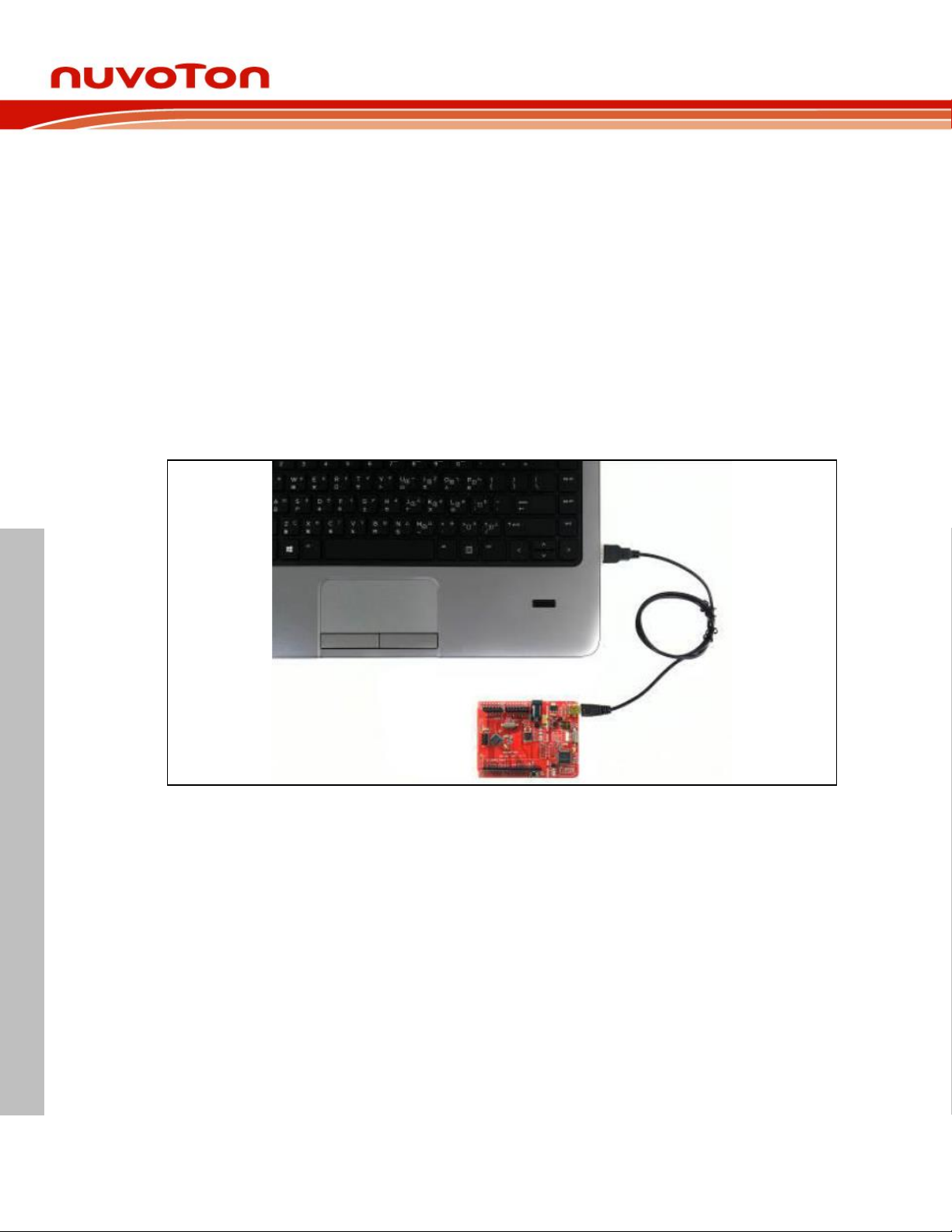
The hardware setup is shown in the figure 6-1. If users want to use the VCOM function, turn on
all the SW2 pins (refer to section 3.1.2).
Figure 6-1 NuMaker UNO Connected to the Computer
6.4 Procedure for Downloading and Debugging Example Program
This example demonstrates how to download and debug a program on the NuMaker UNO
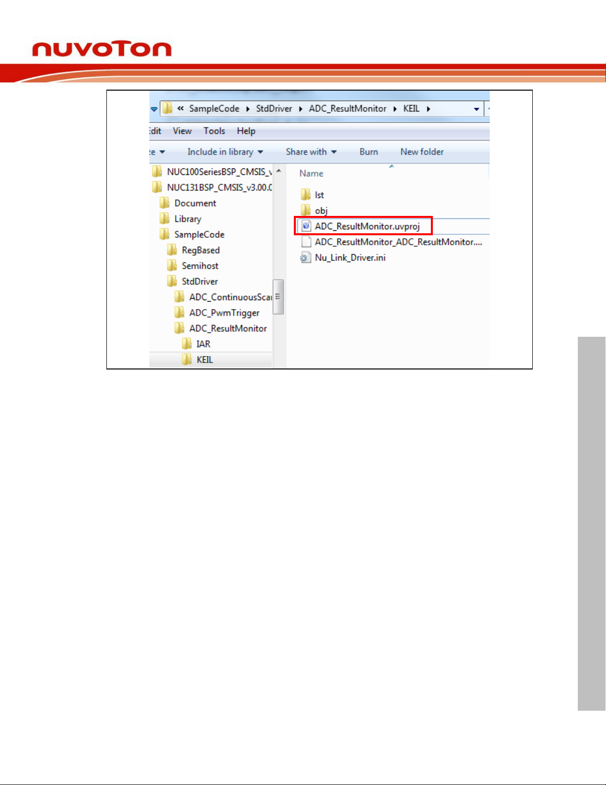
board. The example file can be found in the directory list as shown in the following figure.
6.4.1 Step 1: Open the Project
Please open the following path.
“C:\Nuvoton\BSPLibrary\NUC131BSP_CMSIS_v3.00.001\SampleCode\StdDriver\ADC_Result
Monitor\KEIL”
Aug 20, 2018 Page 26 of 43 Rev 1.02
Page 27
NuMaker UNO
NUMAKER UNO USER MANUAL
Figure 6-2 ADC Sample Program
6.4.2 Step 2: Check Device Chip and Debug Chip
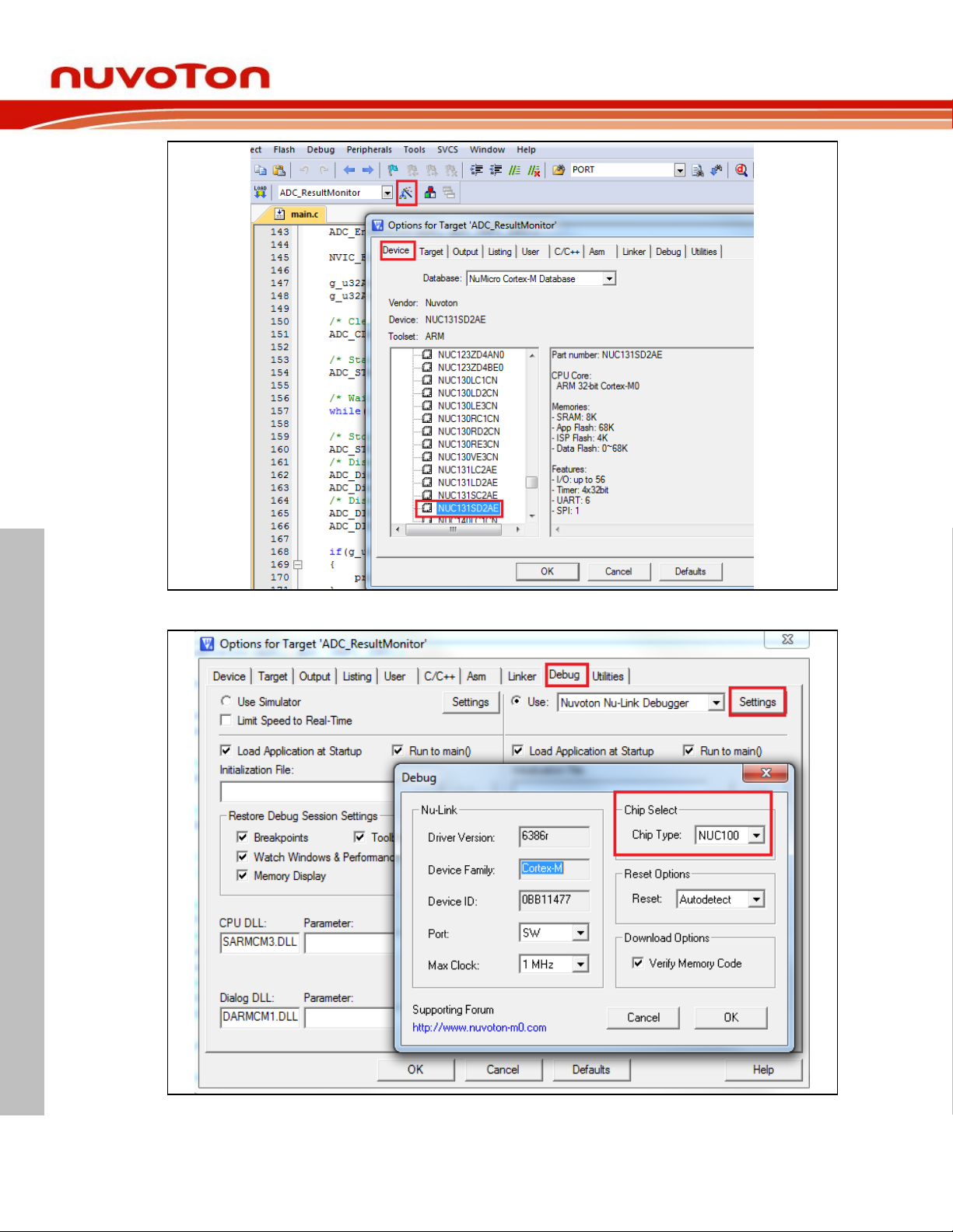
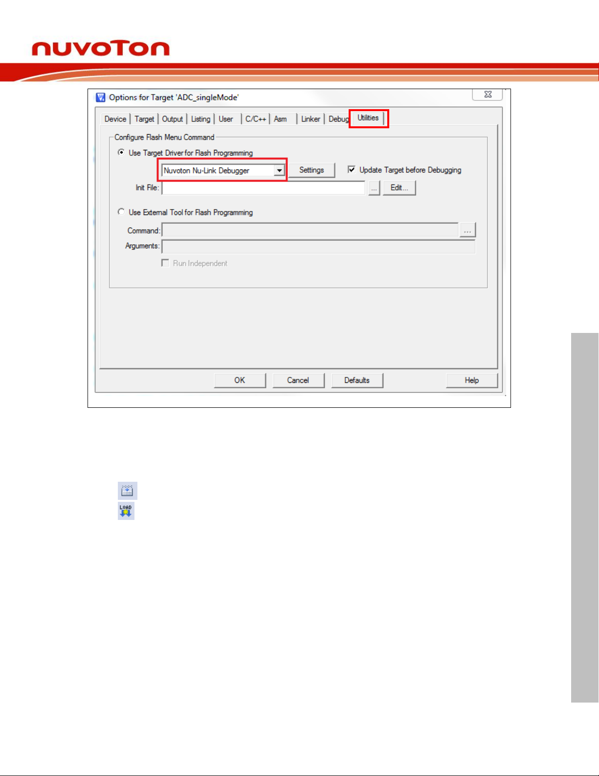
Please open the “target options” to check the device chip and if the debug chip selection is
correct. Figure 6-3 shows the correct device chip selection. Figure 6-4 shows the correct
debug chip selection. Figure 6-5 shows the debugging tool to confirm the selection is correct.
Aug 20, 2018 Page 27 of 43 Rev 1.02
Page 28
NuMaker UNO
NUMAKER UNO USER MANUAL
Figure 6-3 Select Device Chip
Figure 6-4 Select Debug Chip
Aug 20, 2018 Page 28 of 43 Rev 1.02
Page 29
NuMaker UNO
NUMAKER UNO USER MANUAL
Figure 6-5 Select Nuvoton Debugger Tool (Nu-Link)
6.4.3 Step 3: Build and Download Sample Code
Click the Build button to see the completed compilation for error if any, and finally load the
code to the development board.
Build
Download
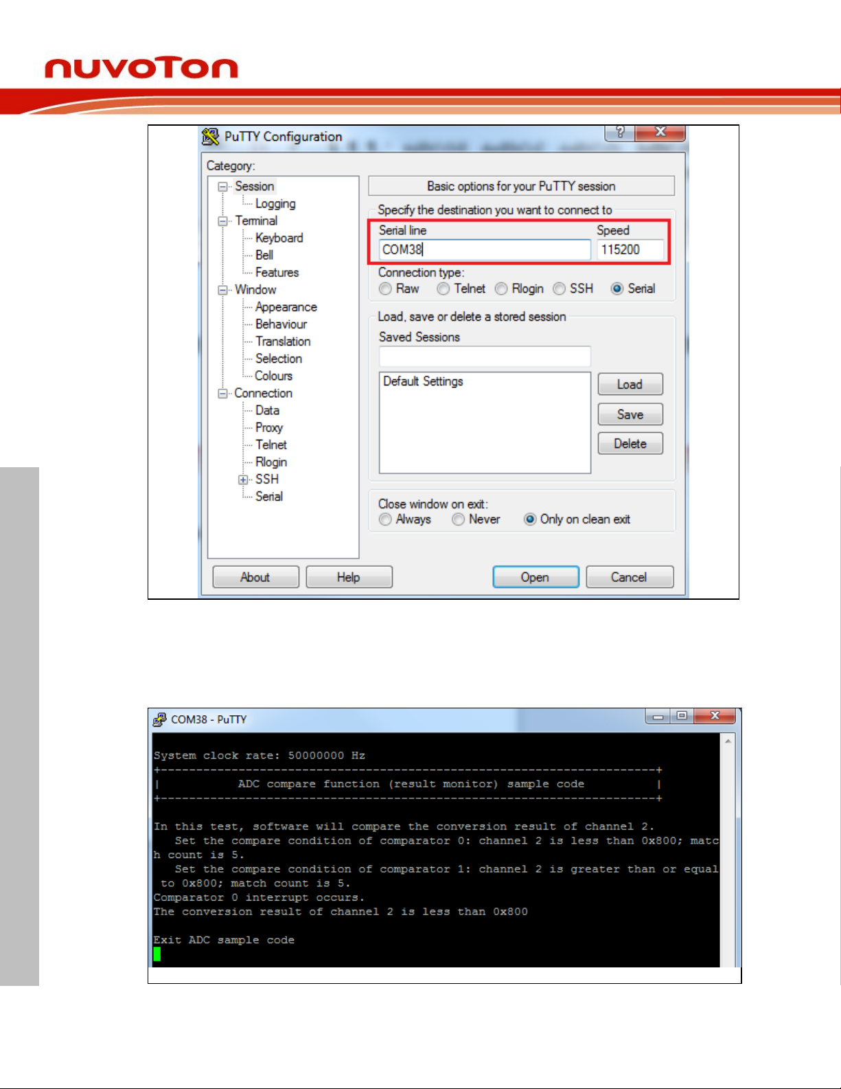
6.4.4 Step 4: Open the Serial Monitor and Set Baud Rate
User can open the serial monitor to print debug message. The present example uses the
“PuTTY tool”.
Aug 20, 2018 Page 29 of 43 Rev 1.02
Page 30
NuMaker UNO
NUMAKER UNO USER MANUAL
Figure 6-6 Set the Baud Rate on PuTTY Tool
6.4.5 Step 5: Click the Reset Button to Run Your Code.
After clicking the Reset button, chip will re-execute the program. The debug messages are
displayed as shown below
Figure 6-7 Serial Monitor Window
Aug 20, 2018 Page 30 of 43 Rev 1.02
Page 31
NUMAKER UNO USER MANUAL
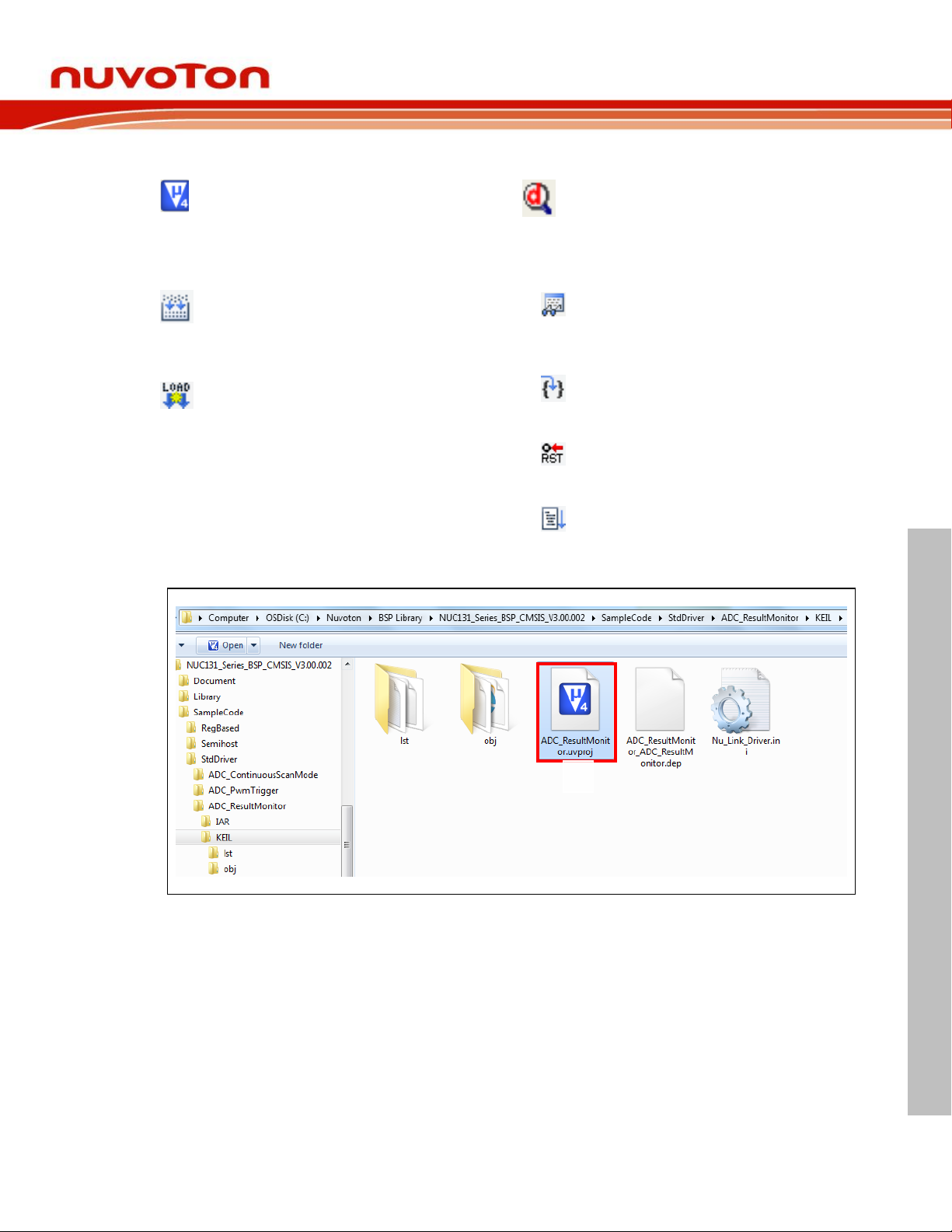
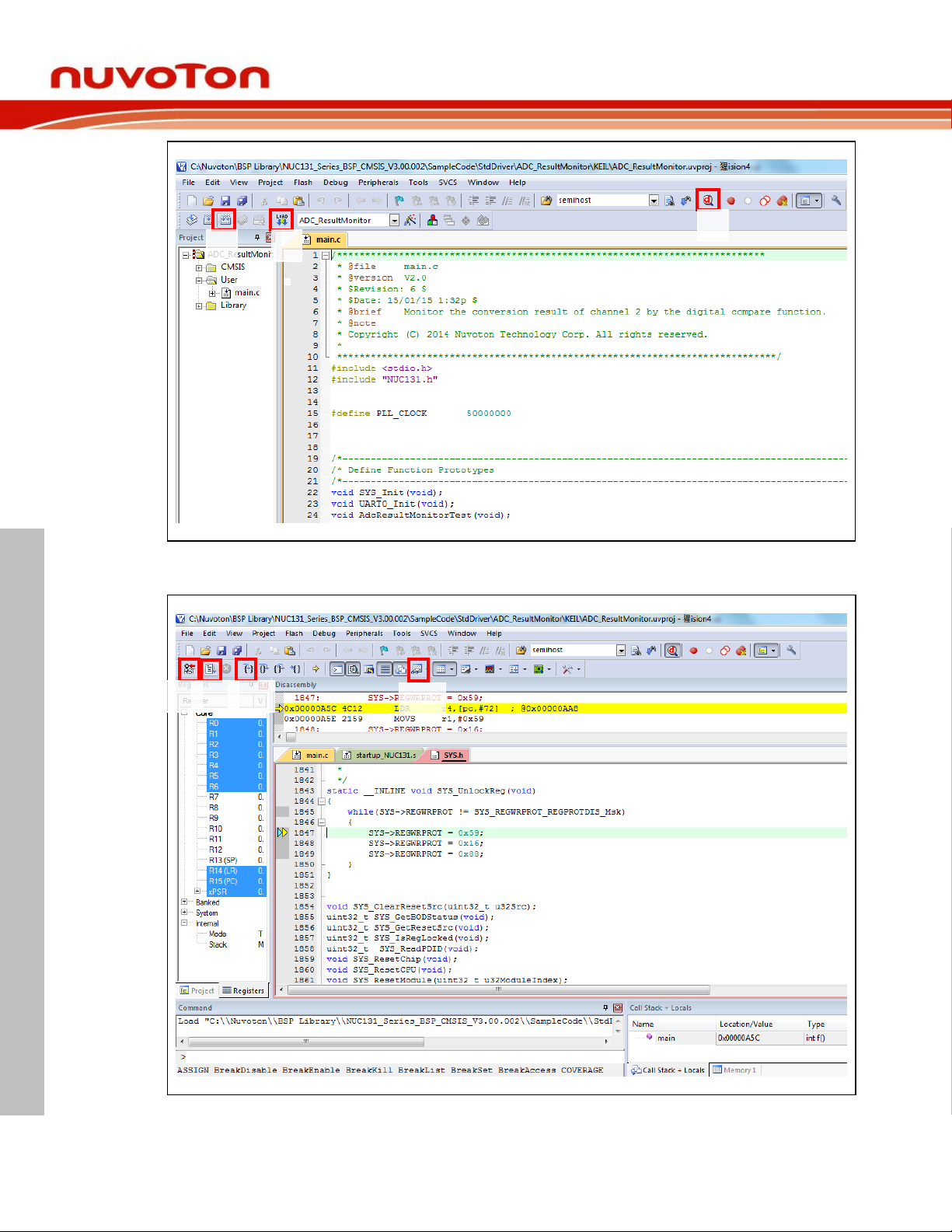
Function Button Description:
1. Open μVision
®
Development Tool
Project – Open
Open the SYS.uvproj project file (Step 1
in Figure 6-8)
2. Project – Build
Compile and link the SYS application
(Step 2 in Figure 6-9)
3. Flash – Download
Program the application code into on-chip
Flash ROM (Step 3 in Figure 6-9)
4. Open Debug Mode (Step 4 in Figure
6-9)
When using the debugger commands, it
has the following features:
a. Window View to detect changes in
the value of variables and registers
(Step 4a in Figure 6-10)
b. Single-Step through code (Step 4b
in Figure 6-10)
c. Reset the device (Step 4c in Figure
6-10)
d. Run the application (Step 4d in
Figure 6-10)
1
NuMaker UNO
Aug 20, 2018 Page 31 of 43 Rev 1.02
Figure 6-8 ADC Sample Code Path
Page 32
NuMaker UNO
NUMAKER UNO USER MANUAL
2
3 4
4a
4b
4c
4d
Figure 6-9 ADC Enter Compile Mode Interface
Figure 6-10 ADC Enter Debug Mode Interface
Aug 20, 2018 Page 32 of 43 Rev 1.02
Page 33
NuMaker UNO
NUMAKER UNO USER MANUAL
7 STARTING TO USE NUMAKER UNO ON IAR EMBEDDED WORKBENCH
7.1 Downloading and Installing IAR Embedded Workbench Software
Please visit IAR official website (http://www.iar.com) to download the IAR Embedded
Workbench and install the EWARM.
7.2 Downloading and Installing Nu-Link IAR Driver
Please visit Nuvoton NuMicro® official website (http://www.nuvoton.com/NuMicro) to download
“NuMicro Nu-Link IAR Driver” file. Please refer to section 8.2 for the detailed download flow.
After the Nu-Link driver is downloaded, please unzip the file and execute the “Nu-
Link_IAR_Driver.exe” to install the driver.
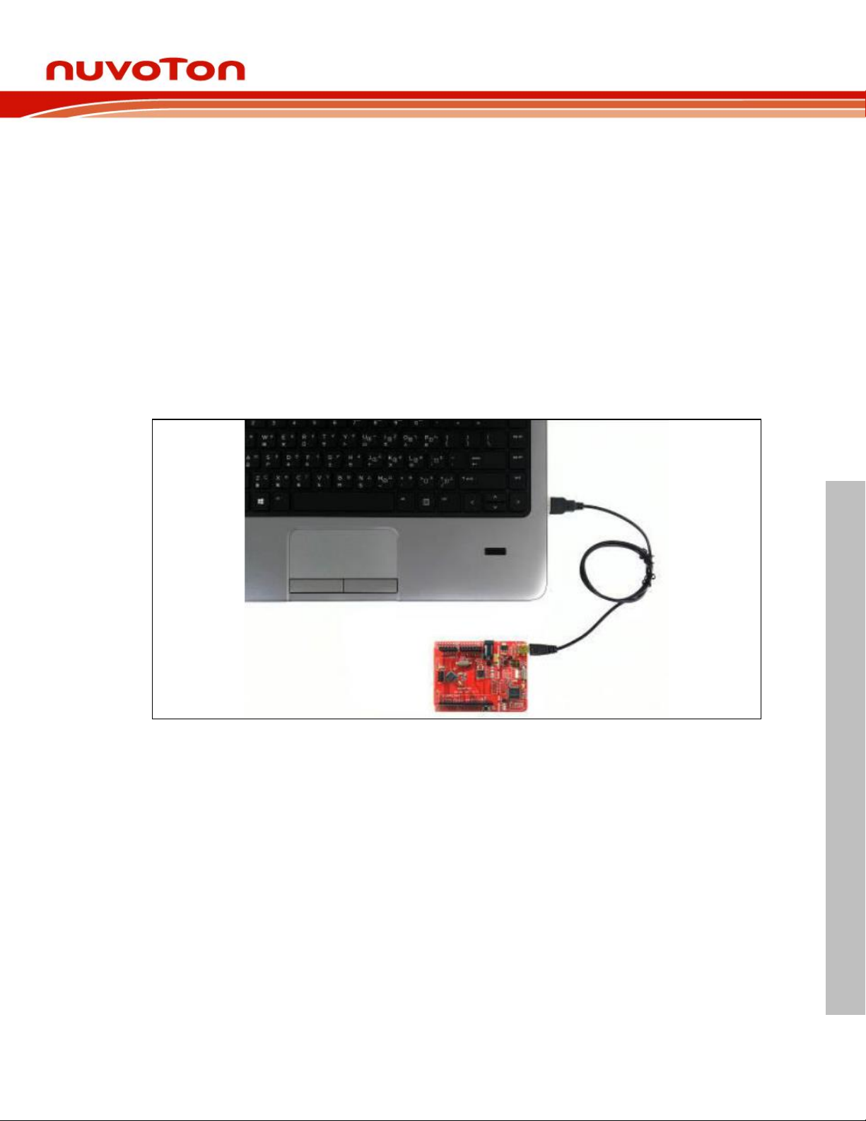
7.3 Hardware Setup
The hardware setup is shown in the figure 7-1. If users want to use the VCOM function, please
turn on all the SW2 pins. Please refer to section 3.1.2.
Figure 7-1 NuMaker UNO Connected to the Computer
7.4 Procedure for Downloading and Debugging Example Program
This example demonstrates how to download and debug an application on a NuMaker UNO
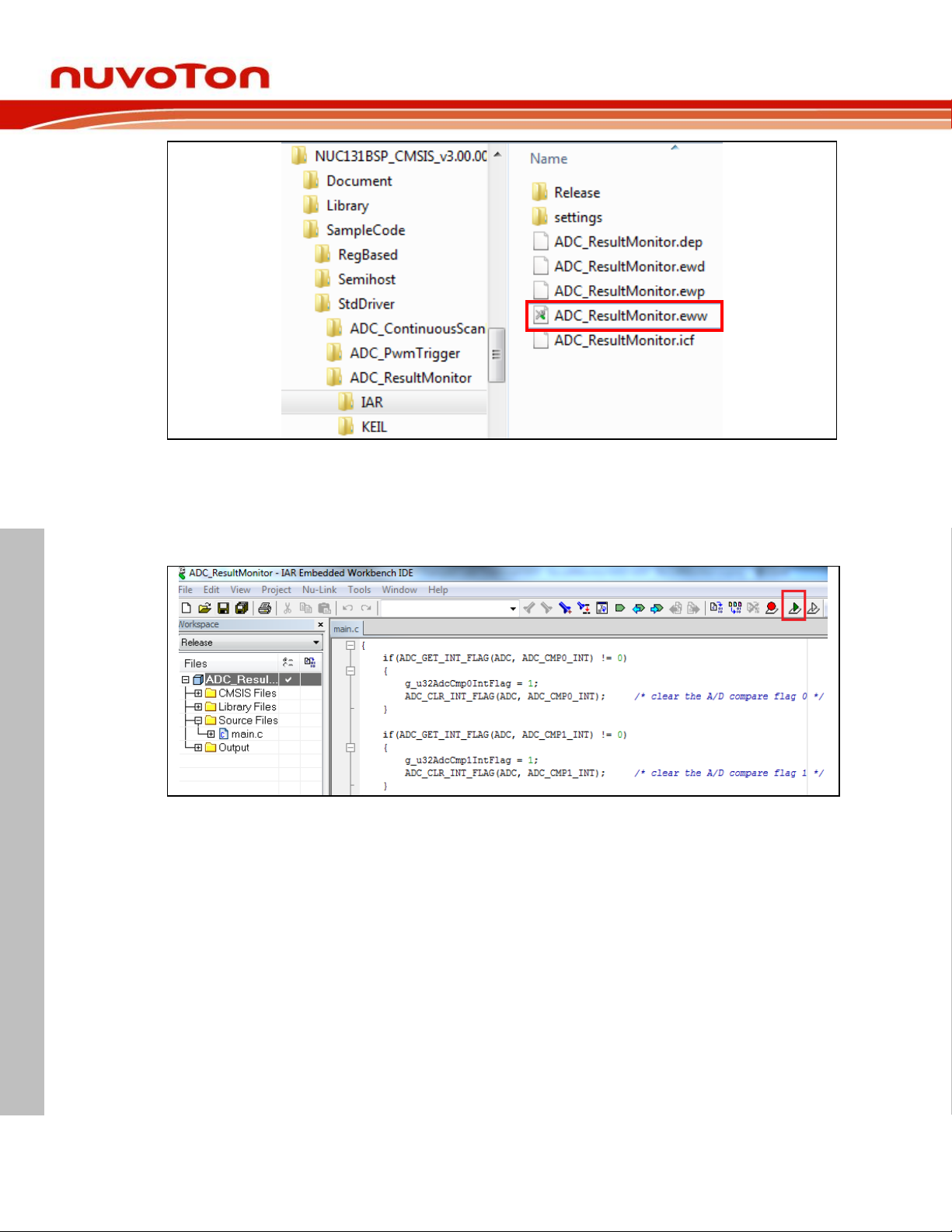
board. The example file can be found in the directory list as shown in the following figure.
7.4.1 Step 1: Open the Project
Please open the following path example program.
“C:\Nuvoton\BSPLibrary\NUC131BSP_CMSIS_v3.00.001\SampleCode\StdDriver\ADC_Result
Monitor\IAR”.
Aug 20, 2018 Page 33 of 43 Rev 1.02
Page 34
NUMAKER UNO USER MANUAL
Figure 7-2 ADC Sample Program in IAR
7.4.2 Step 2: Download the Sample Code.
NuMaker UNO
Click the button on the top right corner to download the program.
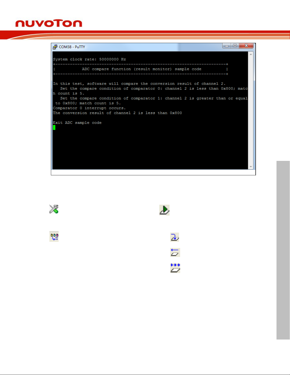
7.4.3 Step 3: Click the Reset Button to Run Your Code
After clicking the Reset button, chip will re-execute the application and debug messages are
displayed.
Figure 7-3 Compile and Load Program in IAR
Aug 20, 2018 Page 34 of 43 Rev 1.02
Page 35
NuMaker UNO
NUMAKER UNO USER MANUAL
Open IAR Embedded Workbench
File – Open – Workspace
Open the SYS.eww workspace file
Project – Make
Compile and link the SYS application
Project – Download and Debug
Program the application code into on-chip
Flash ROM. It has the following features:
Single-step through code
Reset the device
Run the application
Function Button Description:
Figure 7-4 Serial Monitor Window
Aug 20, 2018 Page 35 of 43 Rev 1.02
Page 36
NUMAKER UNO USER MANUAL
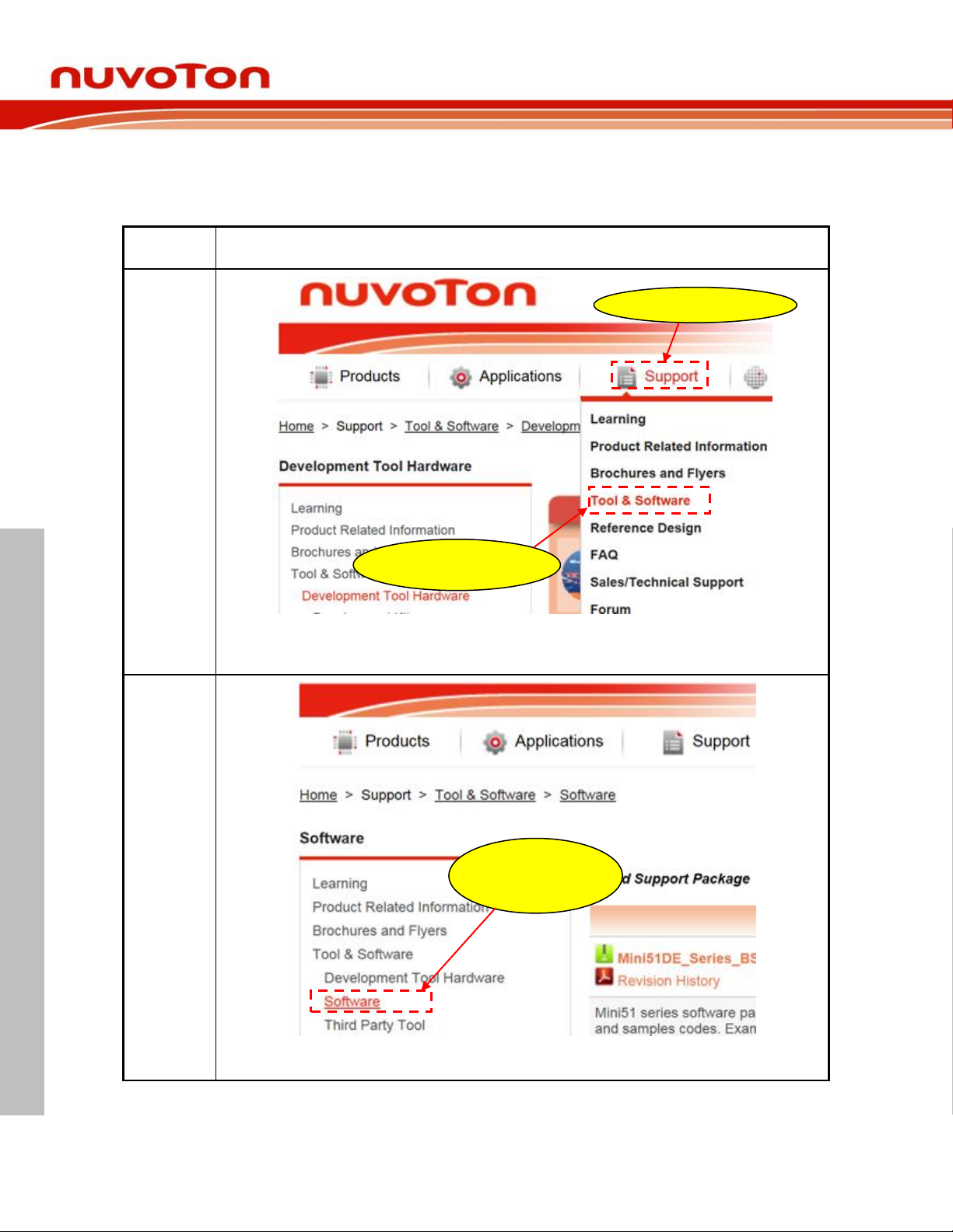
8 DOWNLOADING NU-LINK DRIVER FROM NUVOTON WEBSITE
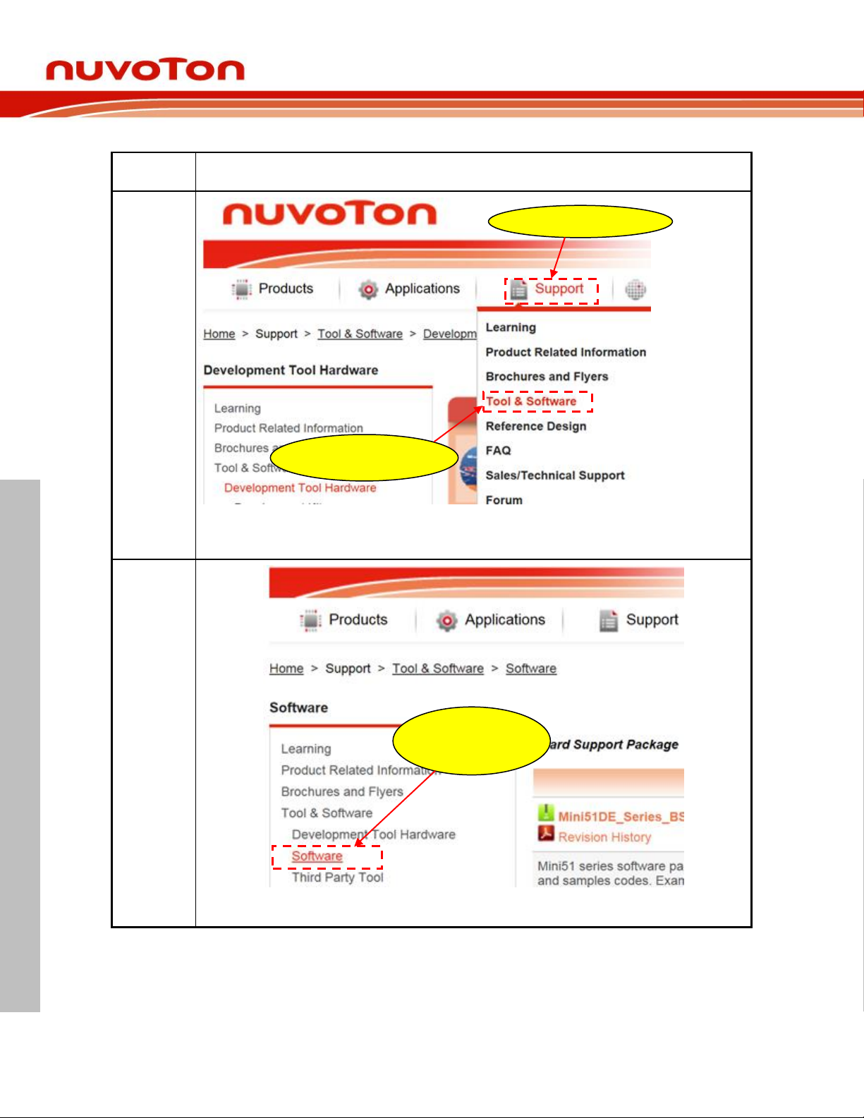
Step 1
Visit Nuvoton NuMicro® Website: http://www.nuvoton.com/NuMicro
Step 2
Step 3
Click here to enter
“Software”
download page
2-2. Click here to enter
“Tool & Software”
2-1. Move to “Support”
8.1 Downloading and Installing Nu-Link Keil Driver
NuMaker UNO
Aug 20, 2018 Page 36 of 43 Rev 1.02
Page 37
NuMaker UNO
NUMAKER UNO USER MANUAL
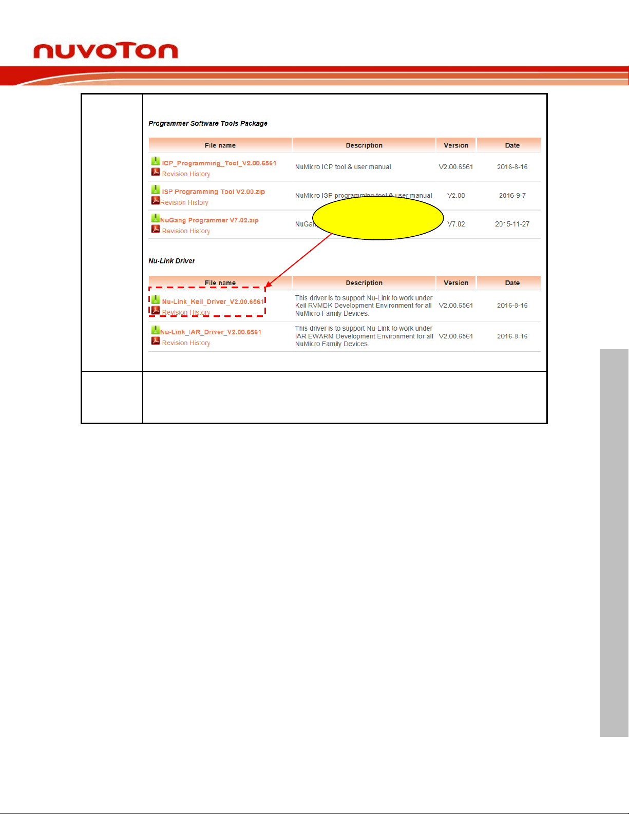
Step 4
Step 5
Download “Nu-Link Driver for Keil RVMDK” file. After download is complete, unzip the file and execute "NuLink_Keil_Driver.exe". Follow the instructions to install Nu-Link Keil driver.
Click here to download
“Nu-Link Keil Driver”
Aug 20, 2018 Page 37 of 43 Rev 1.02
Page 38
NUMAKER UNO USER MANUAL
8.2 Downloading and Installing Nu-Link IAR Driver
Step 1
Visit Nuvoton NuMicro® Website: http://www.nuvoton.com/NuMicro
Step 2
Step 3
Click here to enter
“Software”
download page
2-2. Click here to enter
“Tool & Software”
2-1. Move to “Support”
NuMaker UNO
Aug 20, 2018 Page 38 of 43 Rev 1.02
Page 39
NuMaker UNO
NUMAKER UNO USER MANUAL
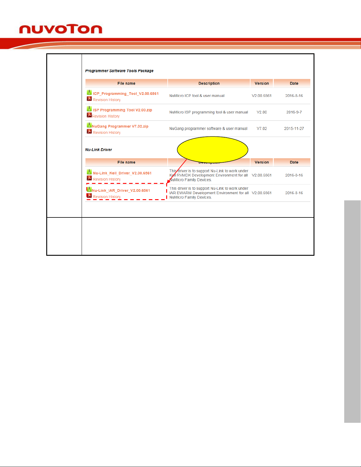
Step 4
Step 5
Download “Nu-Link Driver for IAR” file. After download is complete, unzip the file and execute "Nu-Link_
IAR_Driver.exe". Follow the instructions to install Nu-Link IAR driver.
Click here to
download
“Nu-Link IAR Driver”
Aug 20, 2018 Page 39 of 43 Rev 1.02
Page 40
NUMAKER UNO USER MANUAL
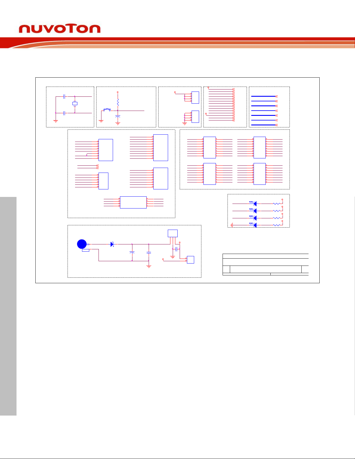
9 NUMAKER UNO SCHEMATICS
UP2
L78M05ACDT
IN1GND2OUT
3
NU5
header 2.54 2X4 公(正面)
SPI0_MISO1VCC
2
SPI0_CLK3SPI0_MOSI
4
RESET5GND
6
SPI0_SS7GPIO
8
N3P18
DVCC5
12
IO2 RED
3.3V
5V
3.3V
5V
N7
Arduino interface
N2
C3
10uF/10V
12
12
IO3 RED
P2
DVCC5
P3
P5
P1
JP3
NC
1 2
3 4
5 6
7 8
9 10
11 12
13 14
15 16
JP4
NC
1 2
3 4
5 6
7 8
9 10
11 12
13 14
15 16
JP6
NC
1 2
3 4
5 6
7 8
9 10
11 12
13 14
15 16
JP5
NC
1 2
3 4
5 6
7 8
9 10
11 12
13 14
15 16
P9
P7
P11
P13
P15
P6
P12
P8
P16
P14
P4
P2
P23
P31
P17
P10
P27
P21
P19
P29
P25
J2
NC
1
2
P22
P20
P30
P24
P32
P18
P28
P26
P33
P39
P47
P37
P35
P45
P41
P36
P46
P34
P40
P48
P44
P38
P42
P49
P55
P63
P51
P61
P57
P59
P53
P62
P50
P56
P64
P60
P54
P52
P58
P43
C8
0.1u
NU3
header 2.54 1X6 母 (正面)
ADC0
1
ADC1
2
ADC2
3
ADC3
4
ADC4
5
ADC5
6
N6
JP2
NC
1
2
3
4
JP1
NC
1
2
3
4
IO
CB6
0.1u
D12MO
DVCC5
PE.[0:15]
PF.[0:7]
PB.[0:15]
PC.[0:15]
PA.[0:15]
PB.[0:15]
PD.[0:15]
PA.[0:15]
PC.[0:15]
PD.[0:15]
PF.[0:7]
PE.[0:15]
R1
10K
RESET
CLKO
3VCC 3.3V
GND
D12MI
LED
PA.9
PA.8
VREF
GND
PB.13
PB.15
PA.12
PA.13
PA.14
PB.11
PE.5
PA.15
PA.11
PA.10
PF.5
PF.4
PB.1
PB.0
Title
Size Document Number Rev
Date: Sheet of
<Doc>
1.5
NuEdu-UNO for NUC131
A4
1 3Monday, May 18, 2015
DVCC5
RESETN5
5VCC 5V
DVCC5
PC.3
GND
GND
IN
CON1
DC-CON
1
2
PA.0
PA.1
PA.2
PA.3
Reset
Crystal
C2
20p
VIN
PA.4
PA.5
R2
510
N1
DVCC5
PC.2
PC.1
RESET
Power
DVCC5
P[1:64]
P[1:64]
Off-page Connector
R3
510
SW1
PUSH BOTTON (B)
R4
510
DVCC5
PC.0
C1
20p
R5
510
ADAVSS
DAVDD
ADAVSS
DAVDD
Off-page Connector
DVCC5
GND
DVCC5
VCC
DVCC5
RESET
3VCC
VREF
RESET
5VCC
VREF
GND
5VCC
3VCC
D12MO
DVCC5
D12MO
D12MI
D12MI
ICERST
CLKO
TICERST
CLKO
VIN
VCC
VIN
input voltage (7V to 12V)
PB.9
CT6
100uF/16V
TANT-D
12
1 2
D3
SS24A
RB060L
VIN
12
IO1 GREEN
NU1
header 2.54 1X8 母 (正面)
NC
1
VDD
2
MCU_RESET
3
3VCC
4
5VCC
5
VSS
6
VSS
7
VIN
8
NU4
header 2.54 1X8 母 (正面)
UART_RX0
1
UART_TX0
2
PWM0
3
PWM1
4
PWM2
5
PWM3
6
PWM4
7
PWM5
8
X1
12MHz
NU2
header 2.54 1X10 母 (正面)
PWM6
1
PWM7
2
PWM8
3
PWM9
4
PWM10
5
PWM11
6
VSS
7
VREF
8
I2C1_SDA
9
I2C1_SCL
10
N4P17
DVCC5
12
POWER1GREEN
9.1 NuMaker UNO I/O Schematic
NuMaker UNO
Aug 20, 2018 Page 40 of 43 Rev 1.02
Page 41
NUMAKER UNO USER MANUAL
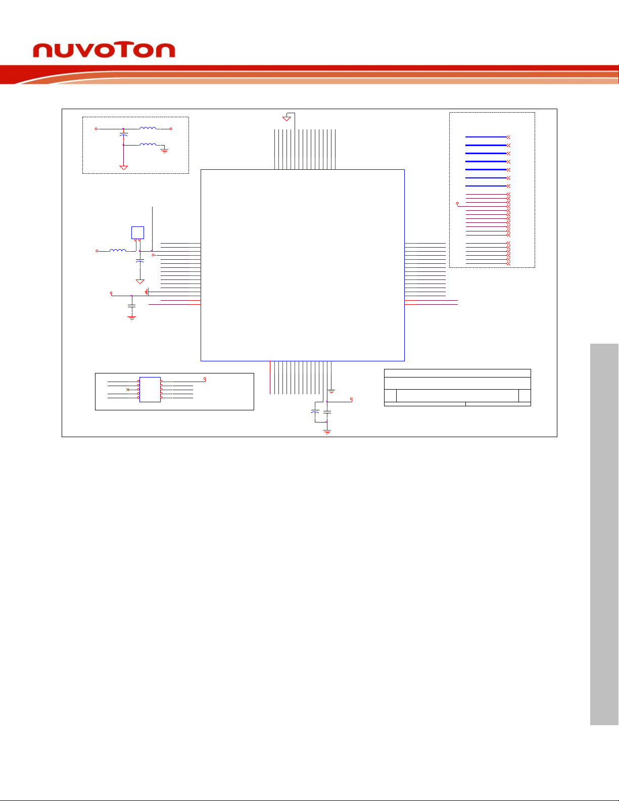
9.2 NuMaker UNO NUC131SD2AE Schematic
P27 PC.1
P28 PC.0
P29 PE.5
CT4
10uF/10V
12
P21 PD.6
P22 PD.7
P23 PD.14
P24 PD.15
P25 PC.3
P26 PC.2
P17 ICER X PB.0
P18 ICETX PB.1
P19 PB.2
CLKO
P20 PB.3
CLKO
P15DVCC5
P54PC.6
P53PC.7
P60RESET
P59D12MI
P58D12MO
P57PB.15
P56PC.14
P55PC.15
P64PB.8CLKO
P63
P61
P50PA.6
P49PA.5
DAVSS
M0_TXD
ICETX
ICERX
M0_RXD
DVCC5
DAVSS
ADAVSS
DVCC5
P51PA.7
DAVDD
P[1:64]
P[1:64]
Off-page Connector
L6FERRITE BEAD
ICETX
D12MO
D12MI
D12MO
D12MI
DAVDD
VCC_connect
ICE_DAT
ICE_CLK
RESET
GND
5V
JP10
NC
1 2
3 4
5 6
7 8
9 10
3.3V
ICERX
ADAVSS
CT5
1uF/16V
12
L7FERRITE BEAD
Title
Size Document Number Rev
Date: Sheet of
<Doc>
1.5
NuEdu-UNO for NUC131
A4
3 3Monday, May 18, 2015
U2
NUC131SD2AE_LQFP64
SPI0_SS0/BPWM0_CH0/PC.0
28
TM1_EXT/TM1/PWM0_CH5/PE.5
29
TM3/PWM0_CH4/PB.11
30
TM2/PB.10
31
TM1/PB.9
32
PA.5/UART3_RXD/ADC5
49
PA.6/UART3_TXD/AD C6
50
PA.7/Vref /ADC 7
51
PB.14/INT01PB.132PB.12/CLKO/BPWM1_CH33PF.5/I2C0_SCL/PWM1_CH54PF.4/I2C0_SDA/PWM1_CH45PA.11/I2C1_SCL/PWM1_CH36PA.10/I2C1_SDA/PWM1_CH27PA.9/I2C0_SCL/UART1_nCTS8PB.4/UART1_RXD10LDO_CAP14VDD15VSS
16
UART0_RXD/PB.0
17
UART0_TXD/PB.1
18
UART0_nRTS/TM2_EXT/TM2/PWM1_BRAKE1/PB. 2
19
UART0_nCTS/TM3_EXT/TM3/PWM1_BRAKE0/PB. 3
20
BPWM1_CH1/PD.6
21
BPWM1_CH0/PD.7
22
UART2_RXD/BPWM0_CH5/ PD.14
23
AVDD
52
PC.7/PWM0_BRAKE1/I2C0_SCL/UART4_RXD
53
PC.6/PWM0_BRAKE0/I2C0_SDA/UART4_TXD
54
PB.15/TM0/TM0_EXT/INT1
57
PC.15
55
PC.14
56
PF.0/PWM1_CH4/XT1_OUT
58
PF.1/BPWM1_CH5/XT1_IN
59
nRESET
60
VSS
61
PB.7/UART1_nCTS13PB.6/UART1_nRTS
12
SPI0_CLK/BPWM0_CH1/PC.1
27
SPI0_MISO0/BPWM0_CH2/ PC.2
26
SPI0_MOSI0/BPWM0_CH3/ PC.3
25
UART2_TXD/BPWM0_CH4/PD. 15
24
VDD
62
PB.8/BPWM1_CH2/CLKO/TM0/STADC
64
PF.8/CLKO
63
PA.8/I2C0_SDA/UART1_nRTS9PB.5/UART1_TXD
11
PWM1_BRAKE1/PC.1133PWM1_BRAKE0/PC.10
34
PWM0_BRAKE1/PC.935PWM0_BRAKE0/PC.8
36
PWM0_CH3/PA.1537PWM0_CH2/PA.14
38
PWM0_CH1/UART 5_TXD/PA. 13
39
PWM0_CH0/UART 5_RXD/PA. 12
40
ICE_DAT/PF.7
41
AVSS
43
ADC0/PWM0_CH4/I2C1_SCL/ UART5_T XD/PA.0
44
ICE_CLK/PF.6
42
ADC1/PWM0_CH5/I2C1_SDA/ UART5_R XD/PA.1
45
ADC2/PWM1_CH0/UART3_T XD/PA.2
46
ADC3/PWM1_CH1/UART3_R XD/PA.3
47
ADC4/PA.4
48
CB4
0.1u
N10
DAVDD
ADAVSS
VREF1
0 ohm
1
2
VREF
ADAVSS
ADAVSS
P43 DAVSS
DVCC5
DAVDD
DAVDD
P52DAVDD
P1PB.14
P2PB.13
SWD Interface
3.3V
5V
3.3V
5V
P3PB.12
P4PF.5
P5PF.4
CT3
10uF/10V
12
P6PA.11
PE.[0:15]
PB.[0:15]
PC.[0:15]
PF.[0:7]
PA.[0:15]
PB.[0:15]
PD.[0:15]
PA.[0:15]
PC.[0:15]
PD.[0:15]
PF.[0:7]
PE.[0:15]
VREF
VREF
P7PA.10
CB5
0.1u
P8PA.9
P9PA.8
P10PB.4
P11PB.5
P12PB.6
P13PB.7
P14
DVCC5
DVCC5
DVCC5
P16GND
P48 PA.4
P47 PA.3
P46 PA.2
P45 PA.1
P44 PA.0
P42 ICE_C LK
P41 ICE_D AT
P40 PA.12
P39 PA.13
P38 PA.14
P37 PA.15
P36 PC.8
P35 PC.9
P34 PC.10
P33 PC.11
DVCC5
VCC_connect
VCC_connect
ICE_DAT
ICE_CLK
RESET
TICECLK
GND
TICEDAT
TICERST
GND
RESET
RESET
P30 PB.11
L8
FERRITE BEAD
P31 PB.10
P32 PB.9
P62N11
NuMaker UNO
Aug 20, 2018 Page 41 of 43 Rev 1.02
Page 42
NUMAKER UNO USER MANUAL
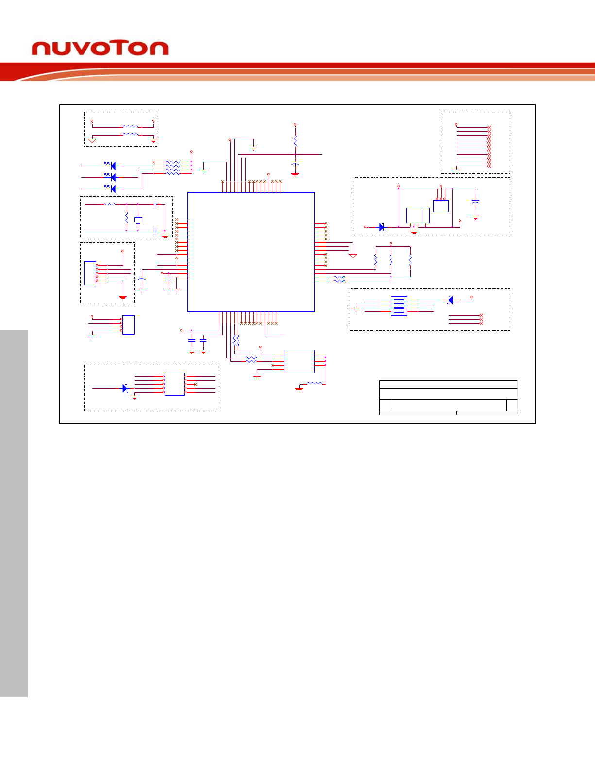
9.3 Nu-Link-Me Schematic
C7
0.1u
N12
L4FERRITE BEAD
5VCC
5VCC
3VCC
3VCC
ICE_RST
RED
ICELED
RP1
8P4R-510
8P4RA
1 2
3 4
5 6
7 8
VCC
GREEN
5V
3.3V
USBVBUS
5V
3.3V
AVDD
ADAVSS
RTDA1
100K
VCC
JP9
NC
1 2
3 4
5 6
7 8
9 10
NUC_RST#
VIN
VIN
3VCC
VCC
RTCK1
100K
VCC_connect
VCC_connect
VCC_connect
CB2
0.1u
VCC
TICEDAT
VCC
RXD
RTDA333
TICECLK
SWD connect
TXD
12
BUSY1
GREEN
TICERST
JP7
NC
1
2
3
4
5
Power select
RRSET1
100K
C5 20p
GND
5V
3.3V
VCOM Switch
R6
10K
ICE_CLK
ICE_RST
ICE_DAT
12MHz Oscillator
CT2
1uF/16V
12
VCC
TICERST
TICEDAT
TICECLK
TICERST
TICECLK
TICEDAT
ICE CONNECT IF
DEBUG
CP1
10uF/10V
12
12M_I N15
DM
DP
R9 0
12M_O
VCOM_pin
1 2 3 4
ON
SW2
HPS604-E
M0_RXD
ICE_RX
ICE_TX
R8
NC
VCC_connect
M0_TXD
J1
mini USB 5pin
GND
5
NC
4
DP
3
DM
2
VCC1SHIELD
6
SHIELD
7
SHIELD
8
SHIELD
9
12
IDLE1
RED
U1
NUC12SRE3DE
PA0/ADC0
44
PA1/ADC1
45
PA2/ADC2
46
PA3/ADC3
47
PA4/ADC4
48
INT0/PB14
1
CPO1/PB13
2
CPO0/PB12
3
VBUS17VDD3318D-19D+20PB0/RX021PB1/TX022PB2/RTS023PB3/CTS024PC2/SDI0026PC1/SPCLK027PC0/SS00
28
PC11/SDO10
33
PC10/SDI10
34
PC9/SPCLK1
35
PC8/SS10
36
PA15/PWM3
37
PA14/PWM2
38
PA13/PWM1
39
X32I
4
X32O
5
I2C1SCL/PA11
6
I2C0SDA/PA8
9
I2C1SDA/PA10
7
I2C0SCL/PA9
8
RX1/PB4
10
TX1/PB5
11
RTS1/PB6
12
CTS1/PB7
13
PC3/SDO00
25
AVSS
43
ICE_CLK
42
ICE_DAT
41
PA12/PWM0
40
LDO
14
VSS
16
VDD
15
ADC/PA5
49
ADC6/PA650ADC7/PA7
51
AVDD
52
CPN0/PC7
53
CPP0/PC6
54
CPN1/PC15
55
CPP1/PC14
56
INT1/PB15
57
XT1_Out
58
XT1_In
59
/RESET
60
VSS1
61
VDD1
62
PVSS
63
STADC/TM0/PB8
64
PE529PB11/TM330PB10/SS01/TM231PB9/SS11/TM1
32
12D2SS24A
VCC
C6
20p
C4
10uF/10V
12
UP1
AMS1117-3.3V
IN3GND1OUT2OUT
4
JP8
NC
1
2
3
4
DM
DP
USBVBUS
Title
Size D ocument Number Rev
Date: Sheet of
<Doc>
3.0
NuLink Me
A4
2 3Monday, March 02, 2015
N14
ICERX
ICETX
1 2
D4
SS24A
M0_RXD
M0_TXD
RTDA20
L5
FERRITE BEAD
12M_I
PVSS
AVDD
VCC
NUC_RST#
12M_O
M0_TXD
1 2
PD1
SS24A
RED
GREEN
VCC
ICELED
USBVBUS
VBUS
USB_D+
USB_D-
ICE_chip_RST
TICECLK
ADAVSS
VCC
M0_RXD
ICE_CLK
ICE_DAT
R11
33
USBVBUS
5VCC
R12
33
ICE_chip_RST
N13
VCC
TICEDAT
JPR1
2&3 (0 ohm)
123
3.3V5V
AVSS
X2
12MHz
R10 0
12
ICE1
RED
AVSS
VCOM_pin
CB3
0.1u
L3FERRI TE BEAD
ICE_TX
R7 33
ICE_RX
NuMaker UNO
Aug 20, 2018 Page 42 of 43 Rev 1.02
Page 43
NUMAKER UNO USER MANUAL
10 REVISION HISTORY
Date
Revision
Description
2015.07.20
1.00
1. Initially issued.
2016.11.02
1.01
1. Changed the board name from NuEdu-UNO to NuMaker UNO.
2. Updated NuMicro® Patch for Arduino 1.5.8 to Nu-Link_USB_Driver_V1.2 in
section 4.2.
3. Added section 3.3 NuMaker UNO NUC131SD2AE Extended Connectors
Layout.
2018.08.20
1.02
1. Update installing instruction in section 4.1, 4.2 .
2. Update NuMaker-UNO package for Arduino 1.8.5
NuMaker UNO
Nuvoton Products are neither intended nor warranted for usage in systems or equipment, any
malfunction or failure of which may cause loss of human life, bodily injury or severe property
damage. Such applications are deemed, “Insecure Usage”.
Insecure usage includes, but is not limited to: equipment for surgical implementation, atomic
energy control instruments, airplane or spaceship instruments, the control or operation of
dynamic, brake or safety systems designed for vehicular use, traffic signal instruments, all
types of safety devices, and other applications intended to support or sustain life.
Important Notice
All Insecure Usage shall be made at customer’s risk, and in the event that third parties lay
claims to Nuvoton as a result of customer’s Insecure Usage, customer shall indemnify the
damages and liabilities thus incurred by Nuvoton.
Aug 20, 2018 Page 43 of 43 Rev 1.02
 Loading...