

Page 1
Nuvo Video Display Systems – User Manual
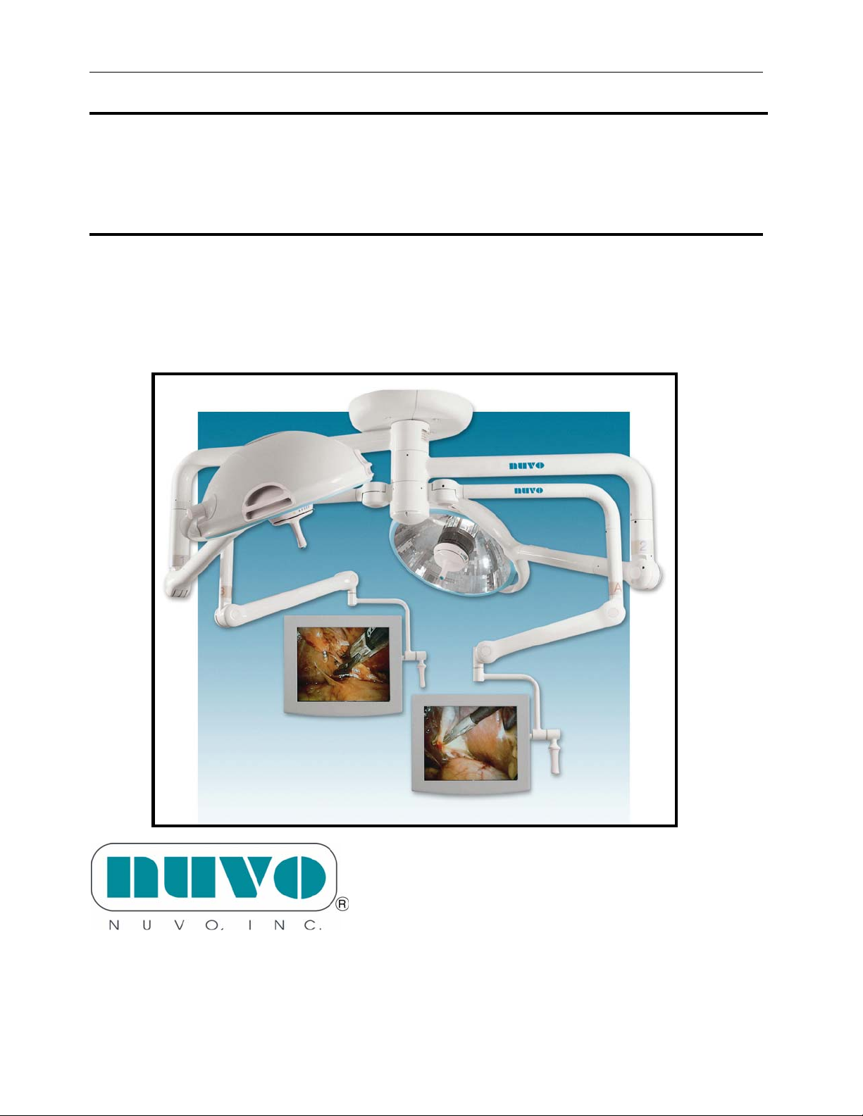
Nuvo Surgical
Video Display System
Model V1360A
USER MANUAL
For Parts or Technical Assistance
USA and CANADA (800) 663-1152
INTERNATIONAL (814) 899-422
M2Z00167 Page 1
Page 2

Nuvo Video Display Systems – User Manual
Table of Contents
Intended Use 3
Product Overview 4
Surgical Monitor Positioning 5
Instructions for Use 6
To Turn the Monitor On/Off 6
To Connect a Video Source to the Video Display System 7
To Connect the Video Display System to a Display or Recording Device 8
To Select a Video Signal for Display at a Monitor Using the Wall Control 9
To Select a Video Signal for Display at a Monitor Using the Monitor Handle 10
To Remove the Sterile Handle and Reinstall 11
To Adjust the Monitor Image 11
Maintenance 12
Cleaning 12
Sterilization 12
Sterilizable Handle 13
Using Optional Sterile Handle Covers 13
Preventive Maintenance 14
Consumable Parts 14
Troubleshooting 15
Nuvo Video Display System Specifications 16
Dimensions 16
Monitor Specifications 16
Environmental Conditions for Transport and Storage 17
Environmental Conditions for Use 17
Mains Power Requirements 17
Vertical Load Characteristics 17
Moment Load Characteristics 17
M2Z00167 Page 2
Page 3
Nuvo Video Display Systems – User Manual
Intended Use
The Nuvo Video Display System
The Nuvo Surgical Monitor is intended to be used primarily by a surgeon to view images
generated by an endoscopic camera.
Introduction
This manual provides the information required for normal operation of the Nuvo Video
Display System. Before operating the Nuvo Surgical Monitor, be sure that you have read
and understand the contents of this manual. It is important that you read and strictly
adhere to the aspects of safety contained in these manuals.
Where applicable, this manual is intended to supplement the Nuvo Surgical Light User
Manual S2Z00125.
WARNING:
It is recommended that a complete back-up display system be available at all times
in case of a total system failure.
CAUTION:
It is strongly recommended the user verify the video system operation before
beginning any procedure.
WARNING:
Do not use the Nuvo Video Display System for radiology diagnosis. Radiographic
images are displayed for reference only. Possible misdiagnosis of the patient could
occur.
WARNING:
Equipment which is not medical grade, but connected to the system, should be kept
out of the patient vicinity. Failure to do so could result in personal injury or
equipment damage.
M2Z00167 Page 3
Page 4
Nuvo Video Display Systems – User Manual
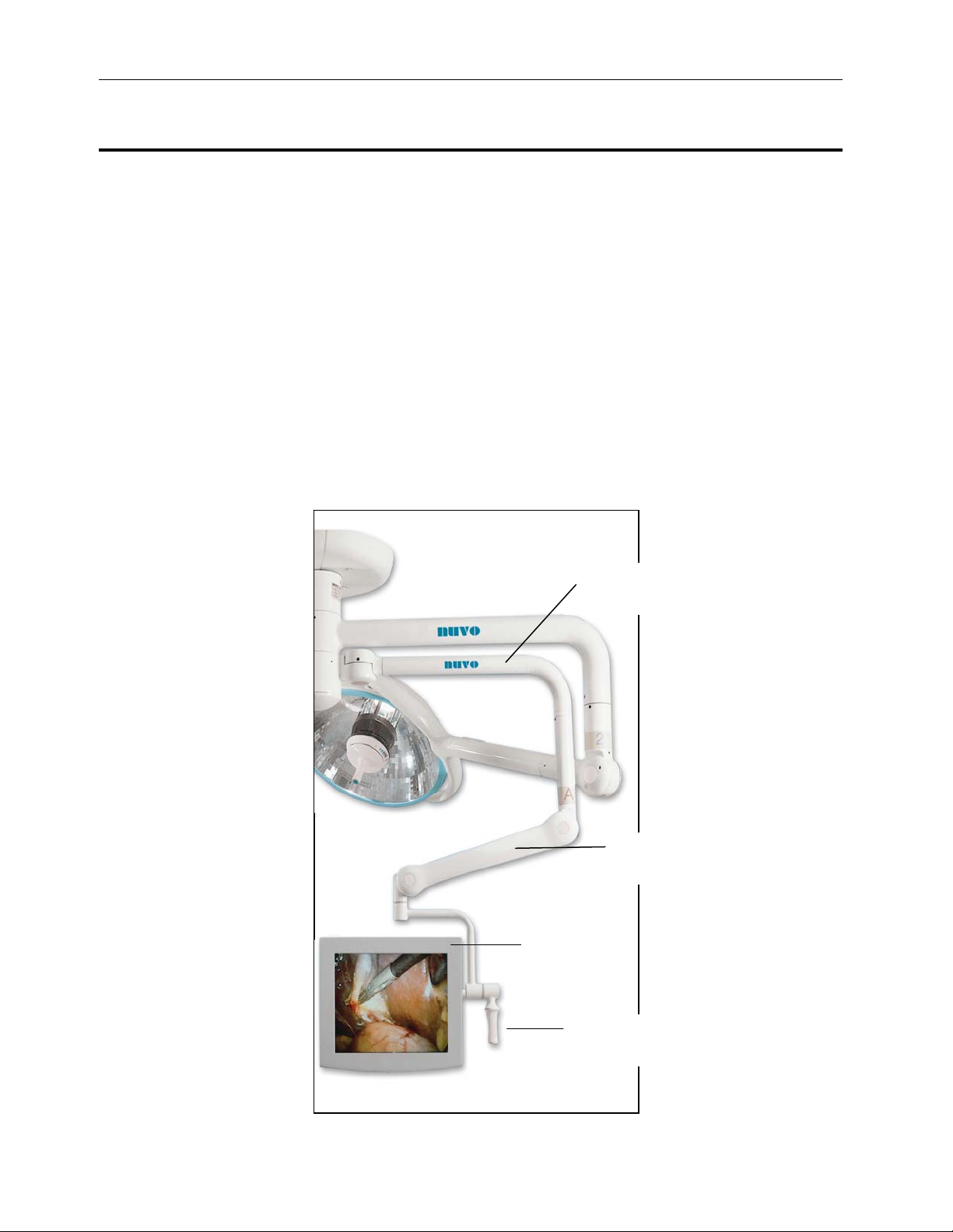
Nuvo Surgical Monitor Product Overview
Positioning
Monitor Features
• Vertical axis rotates 300°
• Monitor rotates 300°
• Drift-resistant positioning
• Minimal airflow disturbance
• Stows out of the way
• Single or dual monitor mounts
• 19" flat-screen medical grade Liquid Crystal Display
• Up to four input channels (with optional switching
system)
• Wall-mounted input/output selector (with optional
switching system)
Maintenance Features
• Easily sterilized positioning handle
• Wires and connectors concealed for cleaning ease
Suspension
Arm
Counterbalance
Arm
Monitor
Assembly
Sterilizable
Handle
M2Z00167 Page 4
Page 5
Nuvo Video Display Systems – User Manual
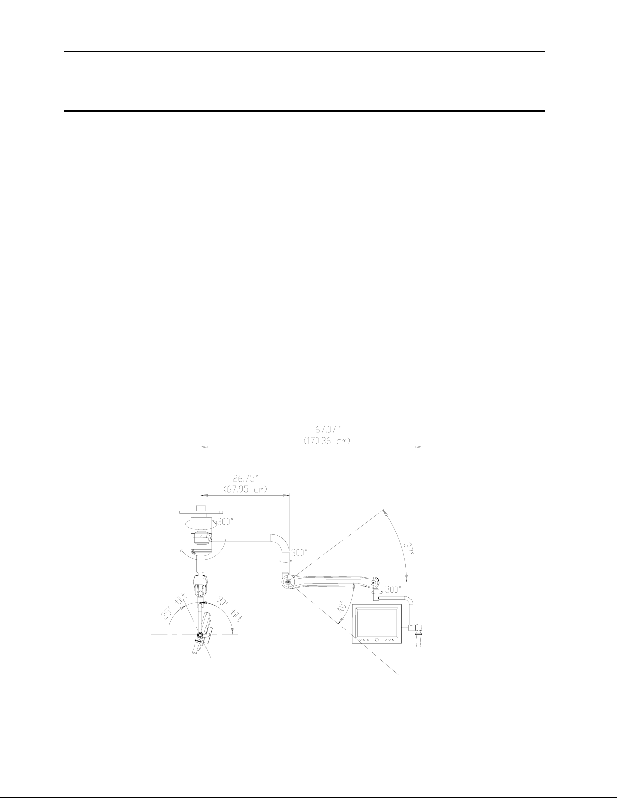
Surgical Monitor Positioning
The Nuvo Surgical Monitor system provides the surgeon with a suspension arrangement that is
well balanced and can be guided easily into position.
The suspension arms rotate 300° around the ceiling mount, and are positioned 180° apart to avoid
interfering with each other. The counterbalance arm rotates 300° around its vertical extension.
These extension pieces are custom-sized according to the ceiling height, assuring adequate
clearance.
The monitor arm turns 300° around the end of the counterbalance arm. The monitor pivots 300°
inside the arm. It can be moved completely out of the way when not in use, without affecting the
light.
The combination of these individual elements allows medical personnel to freely move the
monitor into a variety of positions using only slight pressure on the sterilizable positioning handle.
Once positioned the system remains stable, for optimal viewing of almost any procedure.
If performed by a sterile staff member, grasp the sterilized handle, and position the monitor
assembly in the desired position.
If performed by a non-sterile staff member, grasp the lower edge or side of the monitor (avoid
touching the monitor screen) and position the monitor assembly in the desired position.
190°
M2Z00167 Page 5
Page 6
Nuvo Video Display Systems – User Manual
Instructions for Use of the Nuvo Video Display System
The Nuvo Video Display System is designed to view images from multiple sources, such as
endoscopic cameras, remote video cameras, radiology, pathology, PACS, etc.
Systems may handle up to four separate input signals via an optional video switching board,
although basic systems only handle one input.
Each source can be easily selected and viewed by pressing a button on the wall controls or on
the sterilizable handle at the monitor.
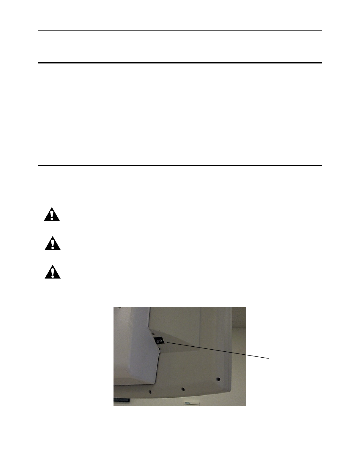
To Turn the Monitor On/Off:
Turn the monitor system on by using the on/off switch located on the back of the
monitor.
CAUTION:
Ensure the monitor is turned off when not in use. Failure to do so will decrease the life of
the monitor.
CAUTION
Some video sources are unstable during their power on sequence – it may be necessary to
turn the monitor power off, then back on for the image to be displayed properly.
CAUTION
The optional video display system requires the monitors are powered on before input
selections are made.
Monitor
On/Off
Switch
M2Z00167 Page 6
Page 7

Nuvo Video Display Systems – User Manual
To Connect a Video Source to the Video Display System
CAUTION:
Take care to align the pins on the connector with the holes in the plug on the
input panel. Do not force the connector into the plug as this may damage the
connector.
Plug the video cable (supplied by others) into a Video Input Panel having the same video format.
Composite Video S-Video RGB Video
NOTE:
The composite video cable must be twisted clockwise to ensure that the cable is securely locked.
The s-video connector can only be inserted in one orientation and does not have any mechanical
retention, other than the friction fit of the pins.
The RGB video cable must be secured with the two small jack screws on either side of the
connector.
M2Z00167 Page 7
Page 8

Nuvo Video Display Systems – User Manual
To Connect the Video Display System to a Display
CAUTION:
Take care to align the pins on the connector with the holes in the plug on the
output panel. Do not force the connector into the plug as this may damage the
connector.
Plug the video cable (supplied by others) into the nearest appropriate Video Output Panel.
NOTE:
Output panels are provided with sockets for each video format available for input signals, with the
exception that Composite video signals are converted to S-Video signals for display and output.
Always ensure that the output signal is compatible with
(a) the signal to be recorded or displayed and
(b) the device to which it will be connected.
NOTE:
Output Panels are labeled Output A and Output B. The signal delivered to Output A duplicates
the signal displayed on Monitor A and, if a second monitor (Monitor B) is provided, then its
display image is duplicated at the Output B panel.
NOTE:
The s-video connector can only be inserted in one orientation and does not have any mechanical
retention, other than the friction fit of the pins.
The RGB video cable must be secured with the two small jack screws on either side of the
connector.
The RS-232 cable must be secured with the two small jack screws on either side of the connector.
This RS-232 port is only configured for use with National Display Systems monitors.
M2Z00167 Page 8
Page 9

Nuvo Video Display Systems – User Manual
To Select a Video Signal for Display at a Monitor Using the Optional Wall
Control
NOTE:
This section applies only to systems with the optional video switching.
NOTE:
The Wall Control Panel is an optional feature and may not be included in the system. Identical
functionality is available from the button, if provided, on the monitor’s sterilizable handle.
1. Determine whether Monitor A or Monitor B is to be switched.
2. Go to the Wall Control, where the bottom panel is dedicated to video switching. Press the
associated button (to the left of the panel for Monitor A, to the right for Monitor B)
repeatedly until the desired image appears on the monitor.
NOTE:
For systems which have a single video source, there is no need for switching and the wall control
panel is not provided.
NOTE:
The video channel selected for display is indicated by one of the four blue LED indicators
associated with that monitor on the panel. If fewer than 4 video inputs are provided, or if
any monitor does not have a video source connected to it, the monitor will show a blank
image when the associated channel is selected.
M2Z00167 Page 9
Page 10

Nuvo Video Display Systems – User Manual
To Select a Video Signal for Display at a Monitor Using the Monitor Handle
NOTE:
This section applies only to systems with the optional video switching.
Video Display Systems with switching capability may be provided with a button at the bottom of
the sterilizable handle adjacent to each monitor. Channel selection is achieved by repeatedly
pressing this button until the desired image is displayed.
NOTE:
The selection button on the handle performs the same function as the selection button at the
optional wall control panel.
NOTE:
This operation should only be performed by a surgeon or other sterile staff member. Operation by
a non-sterile member of staff will contaminate the handle, which should be immediately replaced
with a sterile handle or covered by a sterile disposable cover.
NOTE:
The video channel selected for display is indicated at the wall control panel by one of the four blue
LED indicators associated with that monitor. If fewer than 4 video inputs are provided, or if any
monitor does not have a video source connected to it, the monitor will show a blank image when
the associated channel is selected.
M2Z00167 Page 10
Page 11

Nuvo Video Display Systems – User Manual
To Remove the Sterilizable Handle and Reinstall
To Remove:
Grasp the handle, and rotate it counterclockwise until the handle is loose.
To Install:
• Install the handle onto the monitor cradle.
• Rotate the handle clockwise until fully seated against the O-Ring
• Activate the selection button, if provided, to verify operation.
NOTE:
The Sterilizable Handle must be sterile during surgical procedures. Therefore, suitable
precautions should be taken during installation to ensure that sterility is not compromised. Either
use a sterilized handle or cover a non-sterile handle with a suitable sterile handle cover (i.e., a light
glove or “condom”).
To Adjust the Monitor Image:
For proper procedures to adjust the monitor image, refer to the Monitor Manual.
NOTE:
In some configurations, the monitors are supplied by others, in which case the associated manuals
are not provided by Nuvo Surgical.
M2Z00167 Page 11
Page 12

Maintenance
WARNING:
Cleaning/Sterilization
Cleaning:
Only facility-authorized maintenance personnel should perform maintenance on the
Nuvo Surgical Monitor. Maintenance performed by unauthorized personnel could
result in personal injury or equipment damage.
CAUTION:
Nuvo Video Display Systems – User Manual
Using enzymatic detergents aids in the decontamination process. Measure all detergents carefully,
and use them in accordance with the manufacturer’s instructions.
Take care to avoid the use of cleaning materials that contain high concentrations of alcohol or
chlorine as these may lead to premature aging of the monitor screen.
NOTE:
All surfaces which are within reach of staff should be cleaned between each surgical procedure.
Sterilization:
Sterilization, if desired, can be accomplished by using any FDA-cleared liquid sterilant. In areas
outside of the USA, follow individual facility policies addressing the use of liquid sterilants.
Manufacturer’s recommendations should always be followed.
Care should be taken not to pour cleaning fluids onto the rotating joints or monitor.
It is recommended to use a moist cloth to wipe down the joints and monitor.
Ensure that no moisture seeps into the rotating joints or monitor.
Sterilizable Handle
After every surgical operation:
• Remove the handle from the lighthead
• Wipe with a disposable cloth
• Clean and disinfect in a suitable cleaning and disinfecting machine
• Sterilize the handle
M2Z00167 Page 12
Page 13

Nuvo Video Display Systems – User Manual
The sterilizable handle can be sterilized three ways:
• Cold, by using cleaners recommended for hospitals and authorized by a competent health
authority
• Steam
• Flash in either gravity displacement or pre-vacuum sterilizers
The minimum flash exposure times are shown in the following table:
Handle Cleaning and Sterilization
Sterilize cycle Temperature Exposure Time
Gravity displacement 270-274° F @ 30 psi (132-134° C @ 207
3 minutes
kPa
Pre-vacuum 270-274° F @30 psi (132-134° C @ 207
3 minutes
kPa
NOTE:
The sterilized handle should only be fitted immediately before use.
NOTE:
Service Life of Sterilizable Handle: Frequent sterilization causes natural degradation of the
replaceable handle. If signs of material fatigue such as cracking or discoloration occur, the handle
should be replaced.
NOTE:
If preferred, sterile handle covers can be used, as described below, instead of replacing the
sterilizable handle after each procedure.
Using Optional Sterile Handle Covers
The sterile handle accepts the use of the LiteGlove
equivalent products, from Medical Action or DeRoyal
To install the handle cover, follow these steps:
1. Take the cover from its packaging.
2. Unfold the cover as needed.
3. Install the cover over the sterile handle.
® 1
flexible light handle cover by Devon, or
1
LiteGlove® is a registered trademark of Devin Industries, Inc.
M2Z00167 Page 13
Page 14

Nuvo Video Display Systems – User Manual
Preventive Maintenance
Annual preventive maintenance must be performed by Nuvo authorized personnel to ensure all
feature are functioning as originally designed.
Pay particular attention to:
• The condition of the video input and output connectors
• System drift adjustment. See the picture below for Allen
®
wrench sizes.
Consumable Parts
• Sterilizable handle with Control Button Part number S2A00074
• Sterilizable handle without Control Button Part number S2Z00137
M2Z00167 Page 14
Page 15

Nuvo Video Display Systems – User Manual
Troubleshooting
Image Not Displayed
Monitor not powered on Turn monitor power switch to ON
Video source not powered on Turn video source power switch to ON
Damaged video cable Replace with good cable
Input selection doesn’t match image Re-select the input using the wall control
Incorrect monitor selection Select correct inputs for “A” and “B” monitors
Incorrect input selection Select correct inputs for “A” and “B” monitors
Monitor not in sync with source Turn monitor OFF and back ON
Poor Image Quality
Damaged video cable Replace with good cable
Monitor color settings incorrect Adjust color setting to optimize the video
(see the user manual for the LCD display)
System Drift
Brake(s) set improperly Adjust brakes (see the maintenance section)
M2Z00167 Page 15
Page 16

Nuvo Video Display Systems – User Manual
Nuvo Video Display System Specifications
Dimensions for Product V1360 Nuvo Video Display Systems
Feature Dimension
Counterbalance arm outer clevis to finish floor 78" (198 cm)
Suspension arm inner hub center line to outer hub
center line
Suspension arm inner hub center line to outer most
point on monitor frame
Monitor size 19" (48 cm)
Minimum ceiling height Maintaining a 78" (198 cm) minimum
No light 8' 0" (244 cm)
Single light 8' 7" (262 cm)
Dual light 9' 0" (274 cm)
Monitor Specifications
Feature
19" Vector3 Monitor 19" Radiance/EndoVue Monitor
Screen size 19" (48 cm) 19" (48 cm)
Brightness 250 cd/m
2
Resolution 1024 x 768 Extended
Graphics Array (XGA)
Dot Pitch 0.294 mm 0.294 mm
Viewing angle 170° horizontal
170° vertical
Contrast ratio 600:1 650:1
Input sources Composite
Y/C (S-Video)
RGBS
RGBHV
Storage height (head clearance) 78" (198 cm) 78" (198 cm)
Low position (floor clearance) 49" (124 cm) 48" (124 cm)
NOTE:
The above monitor specifications are applicable to the National Display Systems medical grade
monitors offered by Nuvo Surgical. Alternative models may be provided by others or, for special
configurations, by Nuvo Surgical.
26.75" (68 cm)
67" (170 cm)
counterbalance arm outer clevis to finished floor
Dimension
340 cd/m
2
1280 x 1024 (SXGA)
170° horizontal
170° vertical
Composite
Y/C (S-Video)
RGBS
RGBHV
M2Z00167 Page 16
Page 17

Nuvo Video Display Systems – User Manual
Environmental Conditions for Transport and Storage
Description Specification
Temperature -4°F(-20°C) to 140°F (60°C)
Relative humidity 20% to 90% non-condensing
Pressure 50 kPa to 106 kPa
Environmental Conditions for Use
Description Specification
Temperature 59°F (15°C) to 95°F (35°C) ambient temperature
Relative humidity range 5% to 80% non-condensing
Mains Power Requirements
Rated Voltage Maximum Current Rated Frequency
100-240 V~ 2.0A~ 50/60 Hz
Ceiling Structure Vertical Load Characteristics
Description Specification
Monitor suspension with two monitors 175 lb (79 kg)
Monitor and single light suspension with two
monitors
Monitor and dual light suspension with two
monitors
Ceiling Structure Moment Load Characteristics
(Based on two monitor arms)
Description Specification
Monitor suspension with two monitors 310 ft-lb (420 N m)
Monitor and single light suspension with two
monitors
Monitor and dual light suspension with two
monitors
275 lb (125 kg)
380 lb (172 kg)
720 ft-lb (976 N m)
1105 ft-lb (1,498 N m)
M2Z00167 Page 17
 Loading...