

Page 1
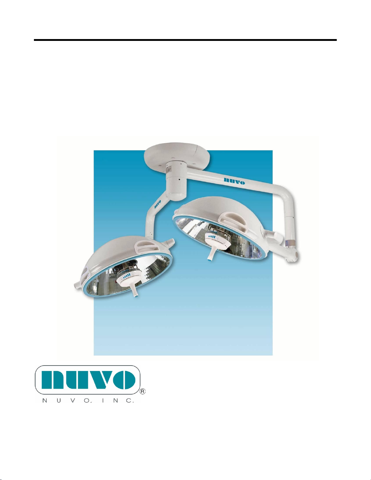
Nuvo Surgical Light
User, Installation, & Maintenance
Manual
Model V1350 Series
For Parts or Technical Assistance
USA and CANADA (800) 663-1152
INTERNATIONAL (814) 899-4220
S2Z00124-05
Page 2

This page left blank intentionally
S2Z00124-05
Page 3

- 3 -
Nuvo Surgical Light
Revision Letter
Pages Affected
Date
Original Issue
May, 2003
Revision 01
16,23.25.28
September 2003
Revision 02
5, 24
April 2004
Revision 03
Cover, 1, 3, 4, 5, 9, 14,
20, 21, 22, 23, 24, 25, 26,
27, 28, 29, 30, 31,
July 2004
Revision 04
All (combined with user
& service manuals)
October 2009
User, Installation & Maintenance
Manual
SIM-S2Z0001 Rev 05 Effective Date 10/25/09
Page 4

- 4 -
© 2003 by Nuvo, Inc. ALL RIGHTS RESERVED.
No part of this text shall be reproduced or transmitted in any form or by
any means, electronic or mechanical, including photocopying, recording,
or by any information or retrieval system without written permission from
Nuvo, Inc. (Nuvo).
First Printing 2003
Printed in the USA
The information contained in this manual is subject to change without
notice.
Nuvo makes no commitment to update or keep current, the information
contained in this manual.
This manual is not applicable to monitor ready light systems.
The only product warranty intended by Nuvo is the express, written
warranty accompanying the bill of sale to the original purchaser. Nuvo
makes no other warranty, express or implied, and in particular, makes no
warranty of merchantability or fitness for a particular purpose.
Additional copies of this manual can be obtained from Nuvo.
SIM-S2Z0001 Rev 05 Effective Date 10/25/09
Page 5

- 5 -
Table of Contents
1.0 User Information .............................................................................................................................. 6
2.0 Installation of the Nuvo Surgical Light ..........................................................................................18
2.1 Check the ceiling structure............................................................................................................. 20
2.2 Ceiling Mounting Plate ...................................................................................................................22
2.3 Base Plate Alignment .....................................................................................................................24
2.4 Vertical Tube Installation ...............................................................................................................27
2.5 Ceiling Control/Transformer Box Installation ................................................................................29
2.6 Optional Wall Control.....................................................................................................................31
2.7 Counterbalance Arm Assembly ......................................................................................................34
2.8 Voltage Adjustments .......................................................................................................................36
2.9 Ceiling Shroud Installation .............................................................................................................39
2.1.0 Final Installation Verification ........................................................................................................40
3.0 Preventive Maintenance ..................................................................................................................41
4.0 Post-installation Inspection ............................................................................................................ 42
5.0 Maintenance ....................................................................................................................................42
5.1 Operator Interface ..........................................................................................................................43
5.2 Electrical System ........................................................................................................................... 44
6.0 Troubleshooting Procedures .......................................................................................................... 50
6.1 Initial Action .................................................................................................................................. 51
6.2 Function Checks............................................................................................................................. 52
6.3 Final Actions .................................................................................................................................. 54
6.4 Surgical Light Does Not Turn On (Lamp Control ) ...................................................................... 54
6.5 Surgical Light Does Not Turn On ( Wall Control ) ....................................................................... 56
6.6 Intensity Level Does Not Adjust ( Lamp Control ) ....................................................................... 58
6.7 Intensity Level Does Not Adjust ( Wall Control ) ......................................................................... 60
6.8 Surgical Light Does Not Turn Off ( Lamp Control ) .................................................................... 62
6.9 Surgical Light Does Not Turn Off ( Wall Control ) ...................................................................... 63
6.0.1 Transformer Control ......................................................................................................................64
6.0.2 Suspension Arm Drift Horizontal ..................................................................................................65
6.0.3 Counterbalance Arm Drift Vertical ...............................................................................................66
6.0.4 Yoke Drift Horizontal ....................................................................................................................67
6.0.5 Lighthead Drift Horizontal ............................................................................................................68
7.0 Lens Removal ...................................................................................................................................69
7.1 Lens Replacement .............................................................................................................................71
7.2 Counterbalance Arm Assembly ........................................................................................................72
7.3 Brakes ................................................................................................................................................75
7.4 Counterbalance Arm Adjustment .....................................................................................................76
7.5 Lighthead Assembly Adjustment ......................................................................................................80
8.0 Replacement Parts .............................................................................................................................81
9.0 Technical Specs ................................................................................................................................90
SIM-S2Z0001 Rev 05 Effective Date 10/25/09
Page 6
- 6 -
Positioning_______
Suspension arms rotate
continuously Lighthead
rotates continuously
Sterile Handle Control
Drift free positioning
Reduction of visual
Clutter Minimal airflow
disturbance
Illumination
Performance_____
Lighting control from inside
the sterile field
Computer modeled reflector
Shadow-free Illumination
Excellent color rendition
Low heat output
Maintenance
Features__________
Built-in backup lighting
Spare bulb storage in
wall control box
Sterile Handle Control
is easily sterilizeable.
1.0 User Information
Intended Use
The Nuvo Surgical Light is intended to provide a field of illumination in surgical,
diagnosis or treatment applications. The single light head configuration is intended for
minor surgical, diagnosis, and/or treatment applications and may be used in the situation
where the treatment or procedure can be interrupted. The dual and triple light head
configurations may be used in operating rooms for all surgical applications and where a
fail safe condition is required; alternatively, two singles, or a dual plus a single, are often
installed.
Introduction
This manual provides the information required for normal operation of the Nuvo Surgical
Light from Nuvo. Before operating the Nuvo Surgical Light, be sure that you have read
and understood in detail the contents of this manual. It is important that you read and
strictly adhere to the aspects of safety contained in this manual.
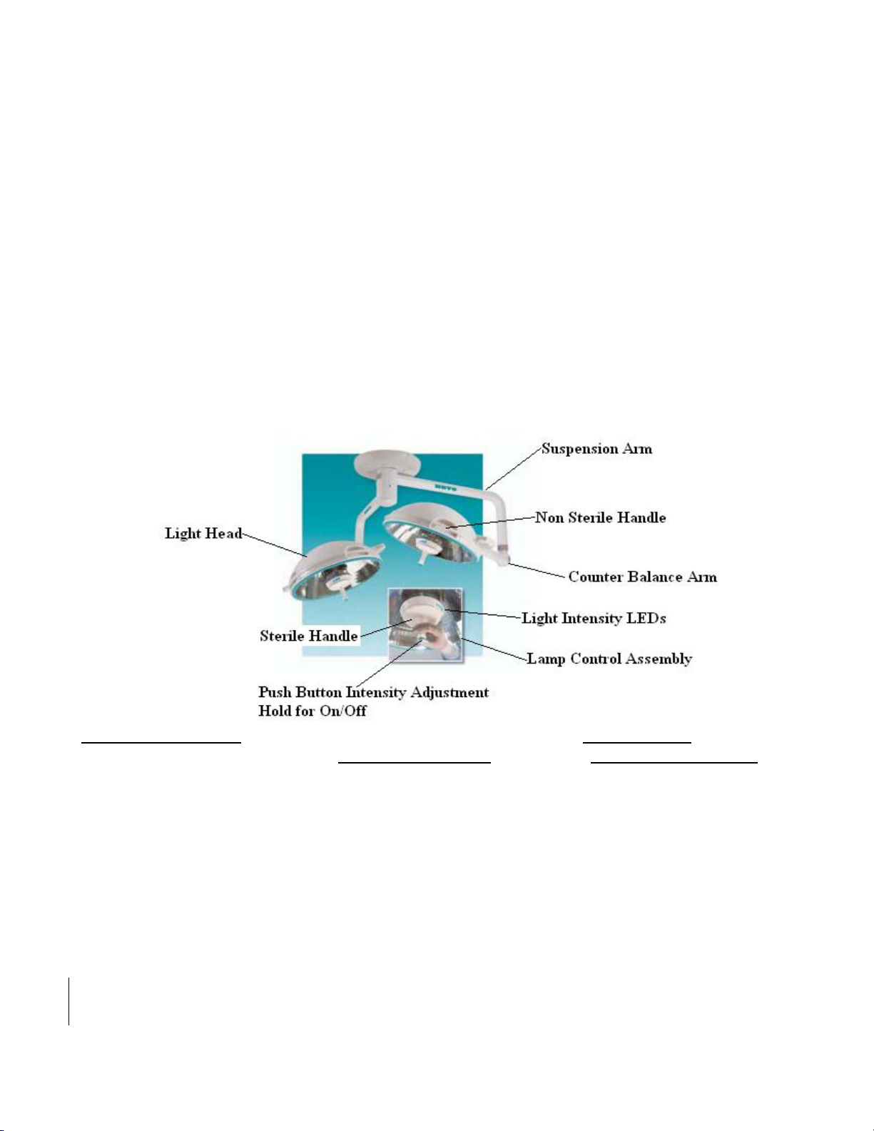
Product Overview
SIM-S2Z0001 Rev 05 Effective Date 10/25/09
Page 7
- 7 -
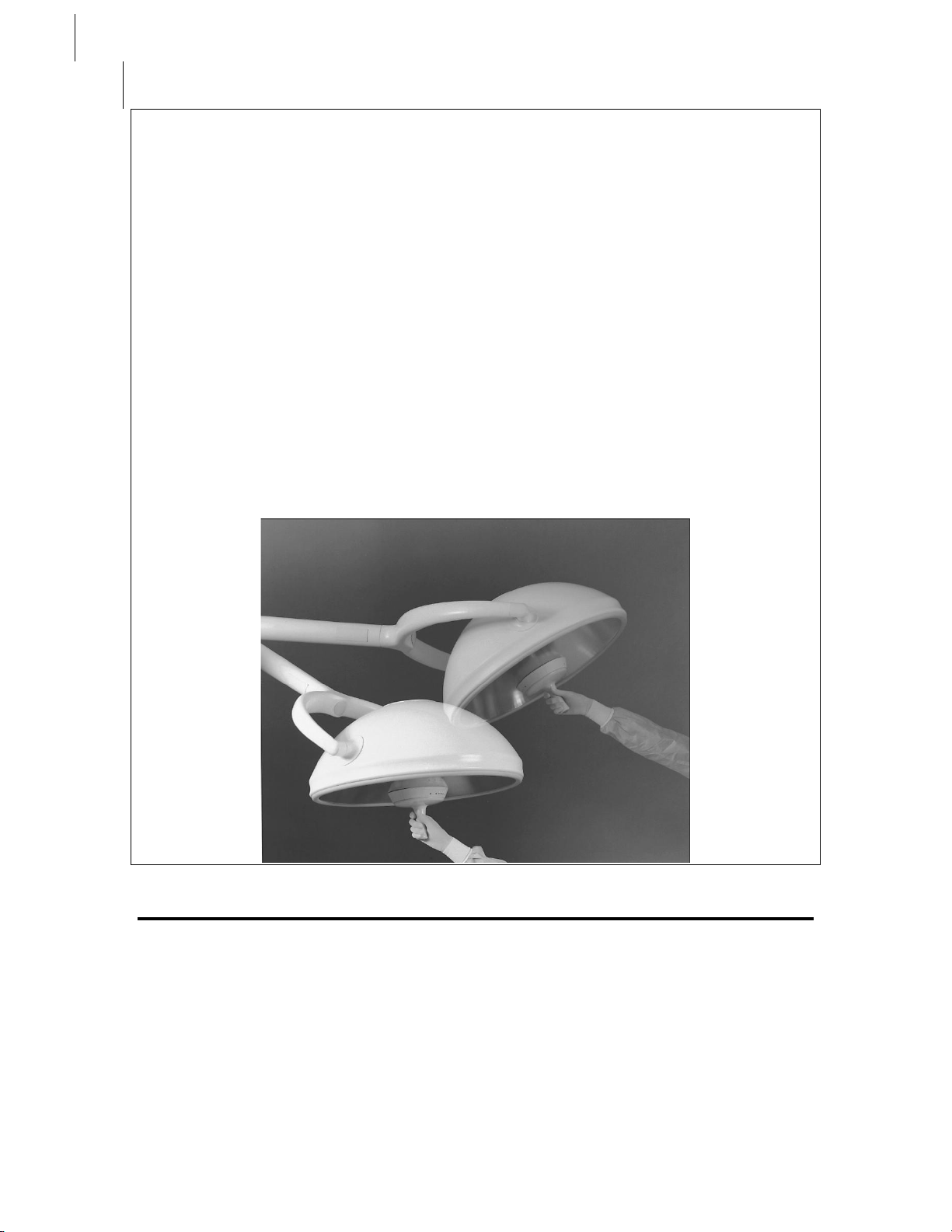
Positioning
The Nuvo Surgical Light provides the surgeon with a suspension system that is perfectly
balanced and can be guided effortlessly into any position.
The upper and lower suspension arms can rotate continuously around the ceiling mount.
The longer upper arm allows both arms to be positioned independently without
interfering with one another.
The counterbalance arms also rotate continuously around their vertical extensions. These
extension pieces are custom sized according to the ceiling height, assuring adequate head
clearance.
The yoke assembly, which holds the light head, turns continuously around the end of the
counterbalance arm. The light head pivots 320° inside the arms of the yoke.
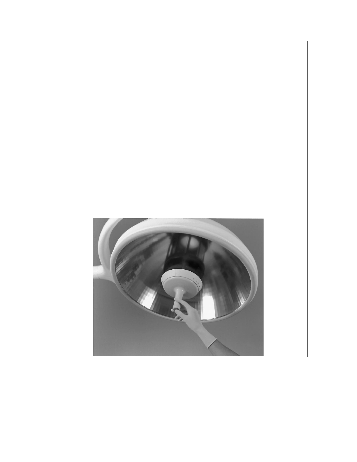
The combination of these individual elements allows medical personnel to move the light
freely into an infinite variety of positions using only slight pressure on the Sterile Handle
Control. Once positioned, the system remains stable, without drifting, allowing focus to
remain where it belongs...on the patient.
SIM-S2Z0001 Rev 05 Effective Date 10/25/09
Page 8
- 8 -
Illumination Performance
• The Sterile Handle Control gives the user full command of the Nuvo Surgical Light.
Positioning, intensity, and pattern size can all be easily controlled from inside the sterile
field. A second set of intensity controls is conveniently located on a wall mounted panel.
• The Nuvo Surgical Light’s compact, 23" (58.4 cm) diameter light head combination
provides color-correct, shadow free illumination well suited to a wide variety of
procedures.
• The perfectly-honed inner reflective surface of the light head features 1890 reflective
facets computer designed for maximum light intensity and shadow reduction.
• With the generation of so many individual light rays, a large percentage of the projected
light can be blocked before any shadow is evident.
• Deep cavity illumination negates the need to refocus midway through a procedure. The
minimum depth of field, without refocusing, is 20" (50.8 cm).
• Each light head delivers 137,000 lux (12700 foot candles) and the color temperature of
the lamp has been optimized at 4300°K to ensure the color clarity of the surgical site.
• The use of a custom designed IR filter reduces emitted IR to a 3.8 μW/cm2fc average.
This low heat output ensures maximum comfort during long procedures.
SIM-S2Z0001 Rev 05 Effective Date 10/25/09
Page 9
- 9 -
Easy Maintenance Features
Backup Lighting and Bulb Replacement
To assure that the Nuvo Surgical Light will offer peak performance on demand, each
Light head is equipped with two bulbs. In the event that the primary bulb burns out
during normal operation, the backup will take over immediately. The changeover
happens so quickly that it is transparent to the user.
The quartz tungsten-halogen bulbs employed in the lamp provide as many as 1000 hours
of uninterrupted light before they need to be replaced. Spare bulbs are conveniently
housed in the wall control box. When necessary, fast, simple bulb replacement can be
accomplished in minutes between cases and without the need for special tools.
Cleaning and Sterilization
Special attention has been given to the aesthetics of the Nuvo Surgical Light. The
smooth, clean lines are visually appealing and aid in the prevention of dust particle buildup. Enhanced streamlining greatly reduces air turbulence over the surgical field.
The Sterile Handle Control is compatible with a wide range of sterile covers. It can also
be easily removed for steam sterilization or cold sterilization.
SIM-S2Z0001 Rev 05 Effective Date 10/25/09
Page 10

- 10 -
Instructions for Use
WARNING:
Do not operate the light if the glass filter is broken or removed. Operation without
the glass filter or with a broken glass filter could cause high levels of ultraviolet
and infrared radiation resulting in injury to the patient or user.
To identify a broken glass filter, inspect for the following:
1. Changes in the light pattern.
2. Loose particles under the lens.
3. Rattling noise when moving the light.
WARNING:
Not for use in areas of explosion hazard. This apparatus is neither approved nor
certified for use in areas where combustible or explosive gas mixtures are likely
to occur.
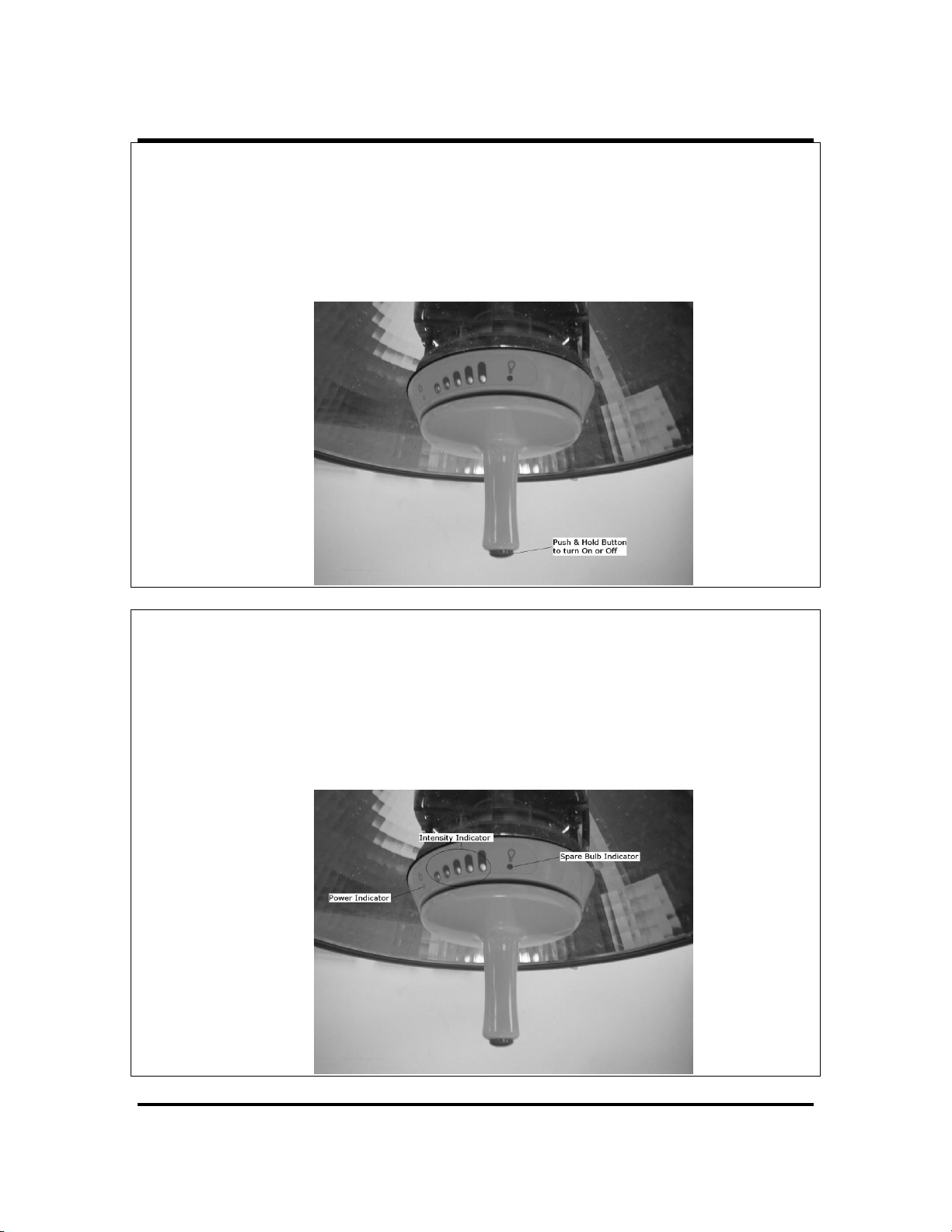
The light can be turned on or off by the use of the push button located at the center of the
sterilizable handle, or by the push button mounted on the wall control unit (both operate
in the same order). The push button on the sterilizable handle overrides the wall control
unit, thereby enabling medical personnel to operate the light in the general vicinity of the
sterile area.
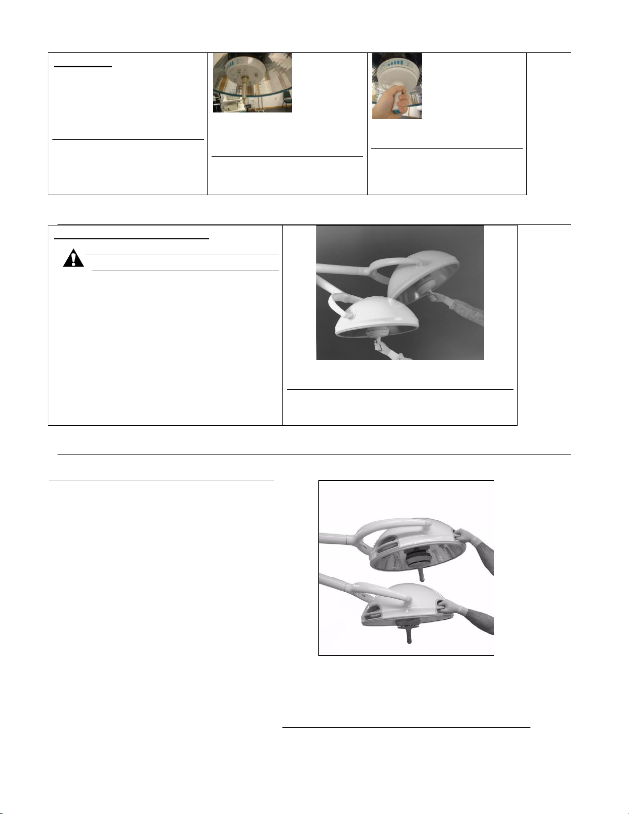
The push button turns the light ON/OFF, and also controls the intensity level of the light.
When the light is turned on, LED’s located on the side of the sterile handle collar, and on
the wall control, illuminates to indicate the intensity level.
SIM-S2Z0001 Rev 05 Effective Date 10/25/09
Page 11
- 11 -
To Turn ON:
Push the button in once, and release. The blue LED’s located on the side of the handle
collar, and on the wall control, illuminate to indicate the intensity level.
NOTE:
After a power outage, the light automatically comes on at the intensity level that it was at
when the power was disconnected.
To Decrease/Increase Brightness Intensity:
Push the button in once, and release. Each time the button is pushed, the level of intensity
is decreased, until only one blue LED is illuminated. The brightness intensity goes back
to full intensity if the button is pushed and released again.
NOTE:
If the button is depressed and held for three seconds, the light goes off.
SIM-S2Z0001 Rev 05 Effective Date 10/25/09
Page 12

- 12 -
On / Off
Button
To Turn OFF:
Push the button in, and hold for three seconds.
The light goes off and all five blue LED’s located
on the side of the handle collar go off.
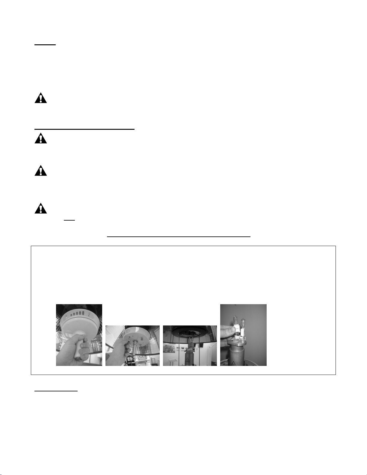
To Change the Light Pattern:
Grasp the handle, and rotate clockwise
to enlarge the light pattern. Rotate
counterclockwise to reduce the light
pattern.
To Remove the Sterile Handle and
Reinstall:
To Remove:
1. Grasp the handle, and rotate
counterclockwise. Remove handle.
SIM-S2Z0001 Rev 05 Effective Date 10/25/09
Page 13
- 13 -
To Install:
1. Inspect the O-ring for wear
or aging and replace if
necessary.
2. Install the handle onto the
light core
3. Rotate the handle
clockwise until fully seated
Step: 1
Step: 2
To Position the Lighthead:
CAUTION:
Do not hang equipment or other
unauthorized items on any part of the
light such as the arms and yoke. This
could cause the light to drift
unnecessarily. Damage to equipment
can occur
Using Central Sterile Handle
Grasp either the central sterile handle or one
of the four non-sterile handles set into the
lighthead cover, and position the lighthead
assembly in the desired position. A nominal
2 lb to 4 lb
(2.7 N·m to 5.4 N·m) force on either handle
produces up and down movement of the
suspension arm and counterbalance arm.
NOTE:
When positioned at any point, the lighthead
assembly moves quietly and smoothly
throughout its range of maneuverability
without drifting.
Using Non-sterile Handle
SIM-S2Z0001 Rev 05 Effective Date 10/25/09
Page 14
- 14 -
Lamps
Two quartz tungsten-halogen lamps are provided for each light head assembly. Only one lamp is
energized at a time. The primary lamp is on the optical center of the light head, while the backup lamp
is displaced slightly from the optical center.
Yellow spare bulb light located on the wall control and on the lamp control assembly illuminate when
the primary lamp is not working. If the yellow lamp is on, replace the primary bulb as soon as possible.
CAUTION:
Use only Nuvo lamp S2Q00006. If other lamps are used, damage to equipment can occur
and performance will be compromised.
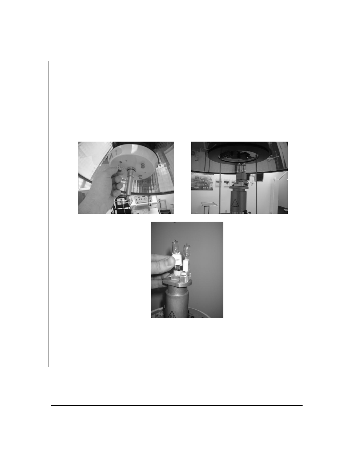
Lamp Removal and Installation:
WARNING:
The lamp is HOT while in operation. Make sure sufficient time is allowed for the lamp to cool
completely before removal, or personal injury can occur.
CAUTION:
Make sure the light head assembly is supported when loosening the four thumbscrews.
Damage to equipment can occur if not done properly.
CAUTION:
Do not touch the lamp bulb. Always grasp the ceramic base, being careful not to touch
the glass of the bulb. Touching the glass could result in damage to the bulb and could
decrease the bulb life. If bulb is touched use alcohol pad to wipe off.
To Remove:
1. Grasp the sterilizable handle, and rotate counterclockwise. Remove the handle.
2. Support the light head by temporarily holding the light head assembly by the yoke or by one of the
four non-sterile handles set into the light head cover.
3. Loosen the four thumb-screws from the light head assembly.
4. Gently lower the light core assembly, leaving it hanging from the four tether rods.
5. Remove and replace the lamp.
Step: 1 Step: 3 Step: 4 Step: 5
To Reinstall:
1. Raise the lamp control assembly, and secure with the four thumbscrews.
2. Inspect the O-ring for wear or aging and replace if necessary.
3. Install the handle, and rotate clockwise until fully seated. Refer to previous steps.
SIM-S2Z0001 Rev 05 Effective Date 10/25/09
Page 15

- 15 -
Cleaning/Sterilization
Sterilize Cycle
Temperature
Exposure
Time
Dry Time
Gravity Displacement
270-274◦ @30psi (132-134◦ C
@207 kPa)
4 min
1 min Flash
20-25 wrapped
Pre-Vacuum
270-274◦ @30psi (132-134◦ C
@207 kPa)
4 min
1 min Flash
20-25 wrapped
Cleaning: Using enzymatic detergents aids in the decontamination process. All detergents should be
measured carefully and used in accordance with the manufacturer’s instructions.
Care should be taken to avoid the use of cleaning materials that contain high concentrations of alcohol
or chlorine as these may lead to premature aging of the lens.
Sterilization: Sterilization can be accomplished by using any FDA approved sterile liquid (USA only).
In areas outside the USA, individual facility policies addressing the use of sterile liquids should be
employed.
Sterilizable Handle
After every surgical operation:
• Remove the handle from the light head
• Wipe with a disposable cloth
• Clean and disinfect in a suitable cleaning and disinfecting machine
• Sterilize the handle
The sterilizable handle can be sterilized three ways:
• Cold by using cleaners recommended for hospitals and authorized by a competent health authority.
• Steam
• Flash in either gravity displacement or pre-vacuum sterilizers.
The minimum flash exposure times are shown in the following table: (Or refer to local codes / facility
your procedures.)
Handle Cleaning and Sterilization
The sterilized handle should only be fitted immediately before use.
NOTE:
Service Life of Sterilizable Handle: Frequent sterilization causes natural degradation to the replaceable
handle. If signs of material fatigue such as cracking or discoloration occur, the handle should be
replaced.
SIM-S2Z0001 Rev 05 Effective Date 10/25/09
Page 16
- 16 -
Optional Sterile Handle Covers
The sterile handle accepts the use of the Devin®1 LiteGlove flexible light handle cover, or equivalent
products from Medical Action or DeRoyal.
To install the handle cover, take the cover from its packaging. Unfold the cover as needed.
Install the cover over the sterilizable handle.
NOTE:
Care must be taken to prevent the cover from interfering with the intensity control button located on
the sterilizable handle.
Handle without the cover installed. Handle with cover installed.
1. Devin® is a registered trademark of Devin Industries, Inc.
SIM-S2Z0001 Rev 05 Effective Date 10/25/09
Page 17
- 17 -
2.0 Installation of the Nuvo Surgical Light
WARNING:
Only facility-authorized personnel should install the Nuvo Surgical Light. Installation performed by unauthorized personnel could result in personal injury or
equipment damage
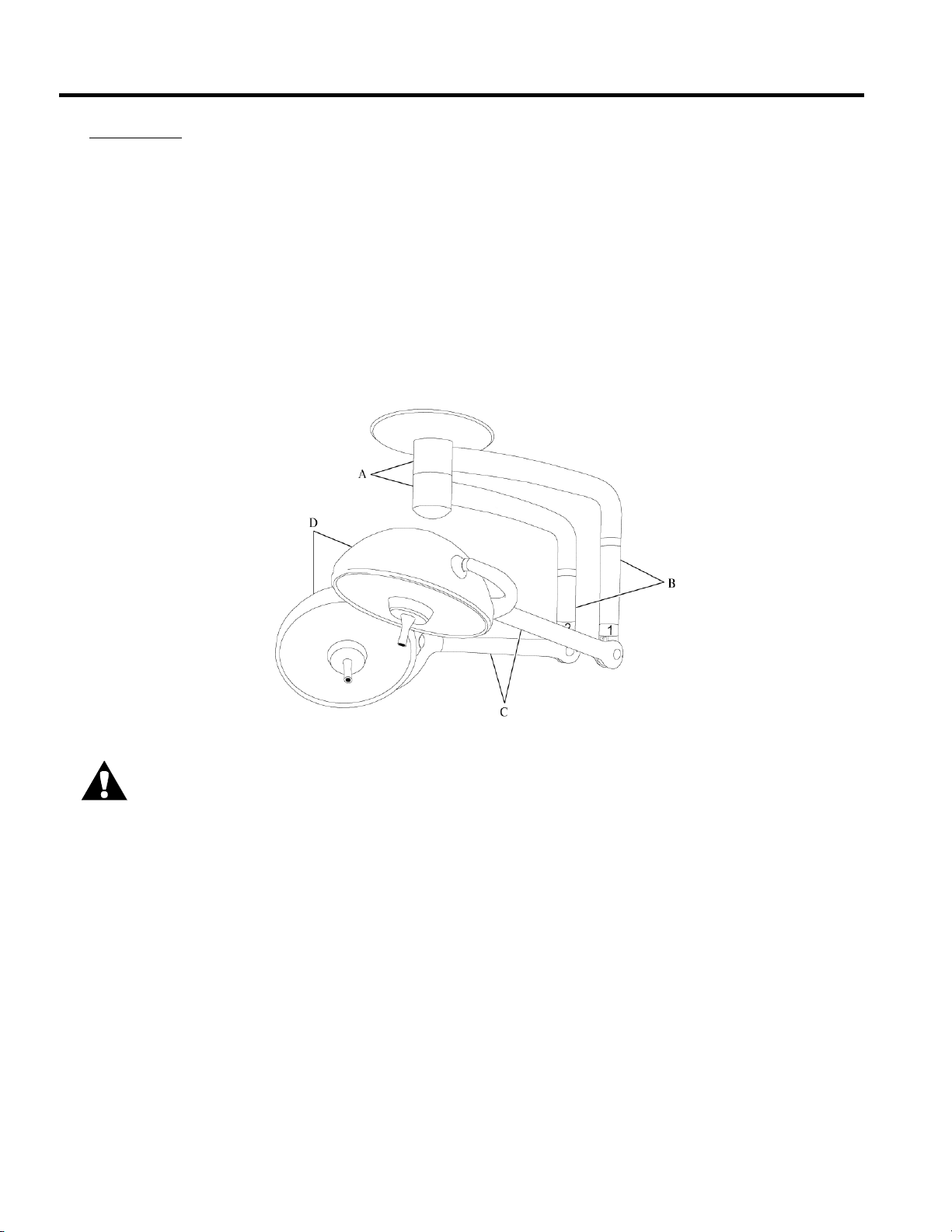
Introduction
This part of the User, Installation & Maintenance manual describes how to install the Nuvo Surgical
Light. Prior to installation, carefully read through and understand all of the installation instructions for
the Nuvo Surgical Light components: the suspension arm assemblies (A), with vertical tubes (B) and
the counterbalance arm assemblies (C) with lighthead/yoke assemblies (D) (see figure below), and
ceiling Control / transformer Box (see figure 12 on) and Wall Control Box (see pages 20 through page
22).
This User, Installation & Maintenance manual is for all models of the Nuvo Surgical Light: 100V,
120V, 220V, and 230/240V.
Figure 2.0.1. Nuvo Surgical Light Components
!
NOTE:
The Nuvo surgical Light must be wired to an emergency power circuit, so in the event of power
interruption, there will be a change over to emergency operation within 5 seconds
SIM-S2Z0001 Rev 05 Effective Date 10/25/09
Page 18

- 18 -
Checklist
Tools required: 1/2"(12.7 mm) drive ratchet 15/16"(24 mm) deep socket
Allen™1 wrench set Phillips head screwdriver
Precision level Tape
(2) Step ladders 3/4"(19 mm) wrenches
3/4"(19 mm) deep socket 15/16"(24 mm) wrenches
Jeweller’s screwdriver True RMS Multimeter
Before installing please check the following:
Height of finished ceiling, and floor to ceiling clearance requirements are met.
Contractor supplied ceiling structure is installed and leveled correctly.
Ceiling structure meets moment and vertical load requirements.
Ceiling structure will not deflect significantly when load is applied.
Clearance requirements for locating the control box above the finished ceiling are met.
Conduit from the wall control box to the ceiling control box.
Access to power is available.
NOTE:
The hole in the ceiling should not exceed 18” diameter on center of the light hub. The ceiling shroud is
20” diameter.
Nuvo Surgical Light Installation
1
Allen™ is a trademark of Industrial Fasteners, Inc.
SIM-S2Z0001 Rev 05 Effective Date 10/25/09
Page 19
- 19 -
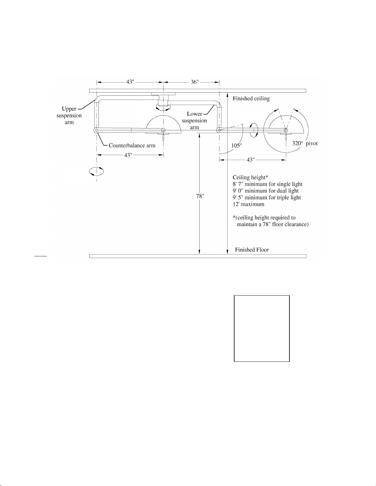
Continuous
Rotation
Continuous
Rotation
Continuous
Rotation
78” = 198 cm
43” = 109 cm
36” = 91 cm
8’7” = 257 cm
9’0” = 274 cm
9’5” = 287 cm
12’ = 366 cm
Conversion Table from inches to
Centimeters.
Before you install the light, check the Clearances.
Figure 2.02. Circular Motion Range
SIM-S2Z0001 Rev 05 Effective Date 10/25/09
Page 20
- 20 -
Configuration
Moment Load
Vertical Load
Single Lighthead
410 ft-lb (556 N-m)
155 lb (71 kg)
Single Lighthead – Monitor Ready
720 ft-lb (976 N-m)
275 lb (125 kg)
Dual Lighthead
795 ft –lb (1078 N-m)
260 lb (118 kg)
Dual Lighthead – Monitor Ready
1105 ft-lb (1498 N-m)
380 lb (172 kg)
Triple Lighthead
1160 ft-lb (1573 N-m)
365 lb (166 kg)
WARNING:
The contractor-installed ceiling structure must not deflect more than 0.062" (1.57mm)
when the load is applied. Improper installation could result in personal injury or
equipment damage.
WARNING:
Verify the minimum finished ceiling height requirement of 8’ 7" (262 cm) for a single
light, 9’ (274cm) for a dual light, and 9’5" (287 cm) for a triple light.
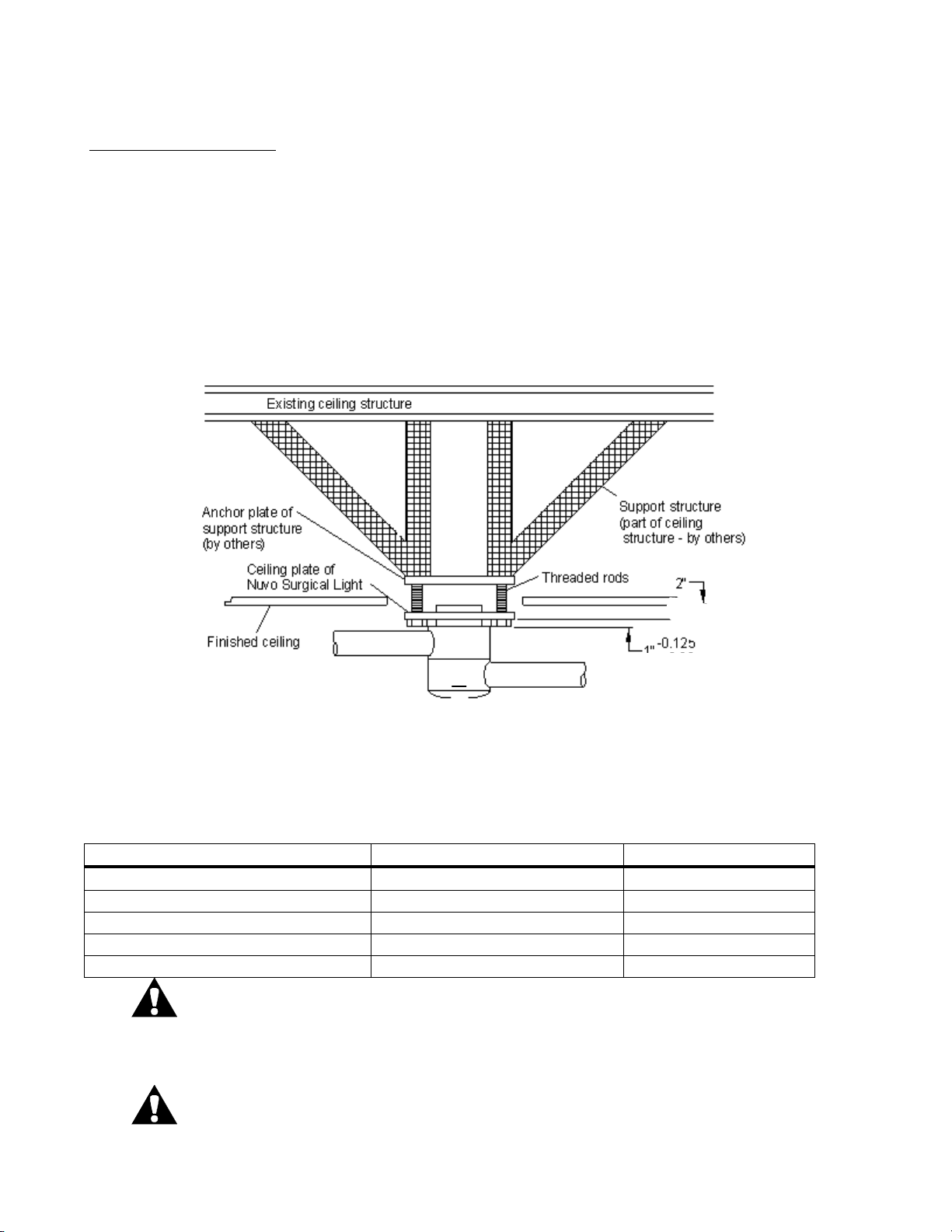
2.1 Check the Ceiling Structure
Ceiling Bearing Strength
The medical facility is required to supply a ceiling structure that is capable of sustaining the load
requirements for the contractor installed lighting system. To accomplish this, it may be necessary to
contract with an architect and certify that the Nuvo Surgical Light can be installed safely. The
following table shows calculated worst case load conditions for mounting single, dual, and triple
lighthead configurations. Worst case is defined as having all arm, monitor, and lighthead assemblies on
the same side of the ceiling plate with the lightheads fully extended from the ceiling plate. Improper
installation could result in personal injury or equipment damage. The contractor-installed ceiling
structure and mounting studs must be capable of supporting the following moment loads and vertical
weights (see figure 2.1.1and table 2.1.1):
Figure 2.1.1. Ceiling Bearing Strength
Ceiling Bearing Strength
Table 2.1.1. Load Requirements for the Nuvo Surgical Light
SIM-S2Z0001 Rev 05 Effective Date 10/25/09
Page 21
- 21 -
Ceiling control / Transformer Box
Monitor Controls
Light Control
Camera Control
Select a suitable location to mount the Ceiling Control Box (if not installed previously) within 50 feet
(15.24 meters) of the Nuvo Surgical Light. The selected location should provide room for a technician
to be able to remove the cover and access the voltage adjustment.
Typical locations include:
above the ceiling next to an access panel,
above the ceiling next to a removable lighting fixture,
above the ceiling of an adjacent hallway with removable panels,
in an electrical cabinet on the wall either inside or adjacent to the OR
The control box for single and dual lights measures 8½"(22 cm) x 16"(41 cm), and for a triple light
8½"(22 cm) x 21 ¼(54 cm). Sufficient room above the box is required to remove the cover and adjust
the voltage. A total height of at least 18" is preferred.
If the ceiling control / transformer box is to be located more than 4’ (four feet) from the mounted light
hub, an extension cable must be ordered. These extension cables are available in 6’, 12’, 18’, 25’ and
48’ lengths.
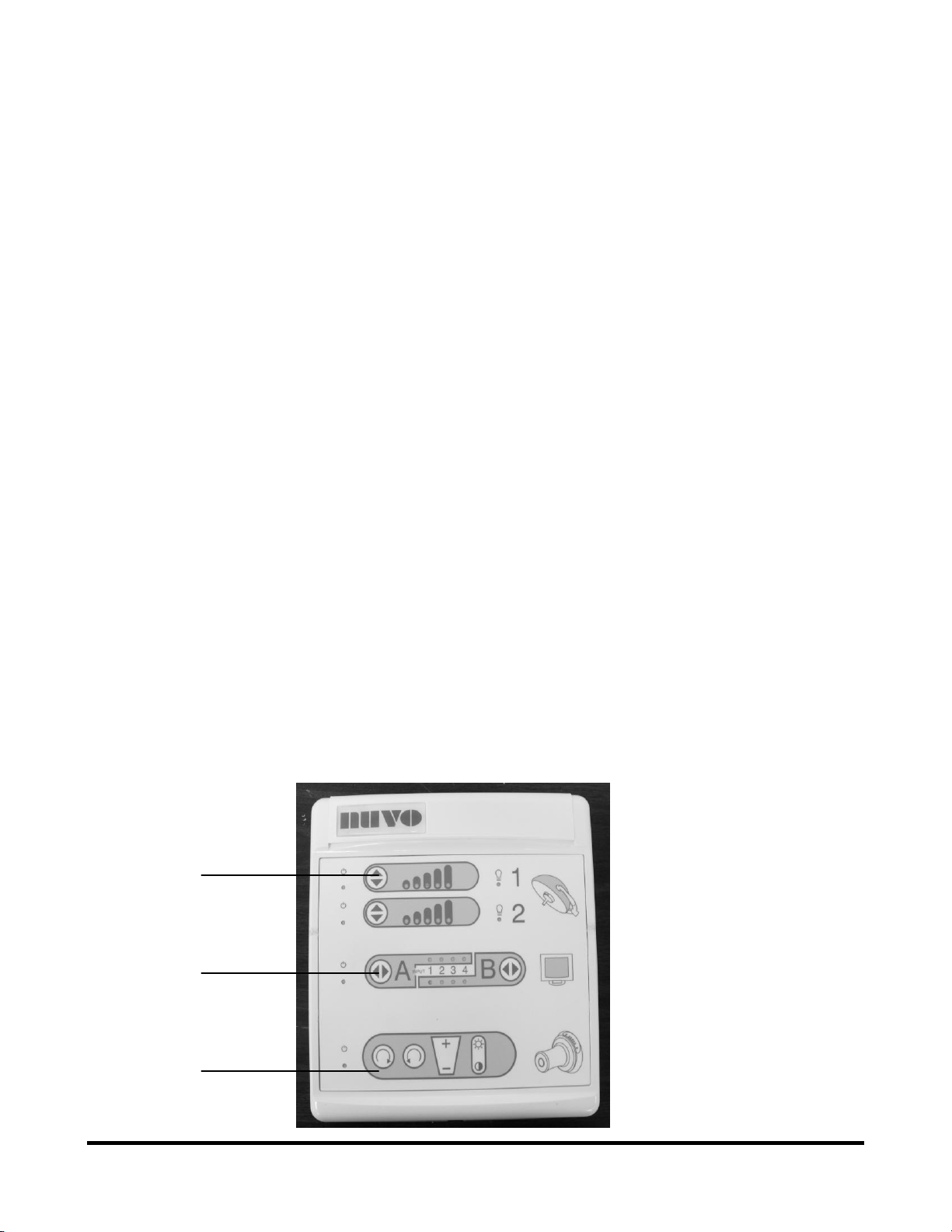
Wall Control Box
The wall control box measures 10" x 10 1/2"(25.4 cm x 26.7 cm) square and is 1 3/4"(4.4 cm) deep. It
connects to a standard two gang 4"(10.2 cm) x 4"(10.2 cm) back box recessed into the wall at
approximately 60” from the floor. A location where this control will be readily accessible to the
circulating nurse should be selected. The wiring harness (35′ 10.67 meters Standard), (50′ 15.24 meters
optional) is then routed from the wall box to the ceiling control box.
Single, dual, or triple light configurations can be operated from a single wall control box. The wall
control contains a discrete set of controls for each lighthead in the configuration. Each is numbered to
correspond to the labels on the suspension arms.
Figure 2.1.2. Wall Control Box
SIM-S2Z0001 Rev 05 Effective Date 10/25/09
Page 22

- 22 -
2.2 Ceiling Mounting Plate Alignment Installation
1. Check the serial numbers on the shipping containers to make sure that the correct Nuvo Surgical
Light is in the correct room.
2. Make sure that the contractor-installed ceiling structure has been properly installed and leveled
(see figure 5 )
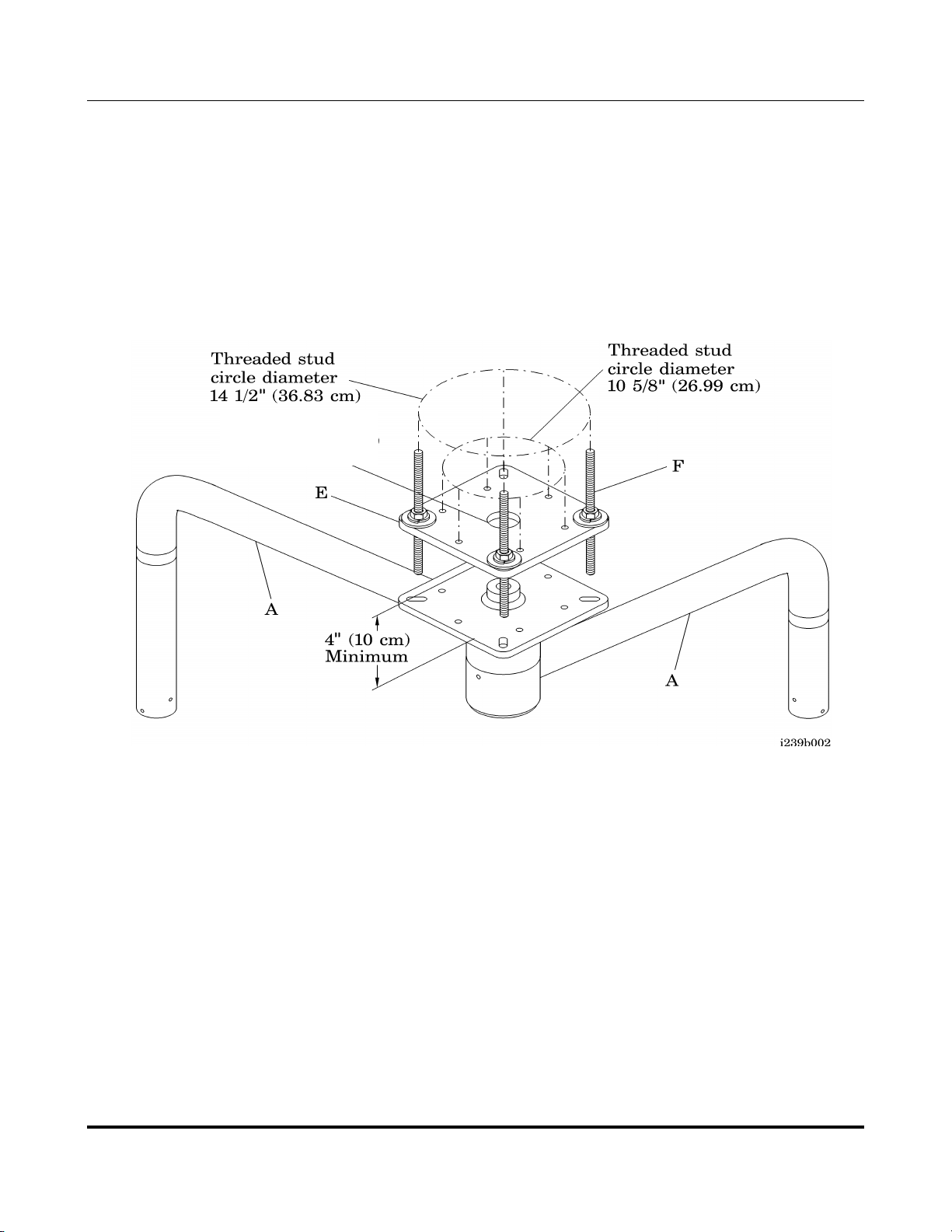
3. Use one of the following mounting hole pattern measurements ( see figure 9 ) to position the
threaded studs (F) for installation of the suspension arm assemblies (A):
Threaded stud circle diameter of 10 5/8" (26.99 cm) for 6 mounting holes
NOTE:
For installation with 6 threaded rods, use a minimum threaded rod size of ½"(12.7 mm) diameter x 13
threads/inch, heat-treated, 4140 alloy steel that is corrosion resistant with a black oxide finish, 125,000
psi tensile strength, and Rockwell C hardness 28-32.
Threaded stud circle diameter of 14 ½" (36.83 cm) for 4 mounting holes (Preferred)
NOTE:
For installation with 4 treaded rods, use a minimum threaded rod size of 5/8"(15.88 mm) diameter x 11
threads/inch, heat-treated, 4140 alloy steel that is corrosion resistant with a black oxide finish, 125,000
psi tensile strength, and Rockwell C hardness 28-32.
SIM-S2Z0001 Rev 05 Effective Date 10/25/09
Page 23
- 23 -
Part Description
Quantity
Anchor plate
1
5/8″(1.6 cm) Threaded rod (min. length 8″(20.3 cm))
(max. length 14″(35.6 cm))
4
5/8″(1.6 cm) x 1 1/2″(3.8 cm) hardened washer
16
5/8″(1.6 cm) nut
16
Bottom Surface of the
base plate
2 1/4" (5.72 cm)
Mounting Plate Alignment Installation
Table 2.2.1 Recommended Ceiling Mounting Plate Configuration Installation Parts
NOTE:
The ceiling structure, treaded rods, nuts, lockwashers, and washer are to be supplied by others.
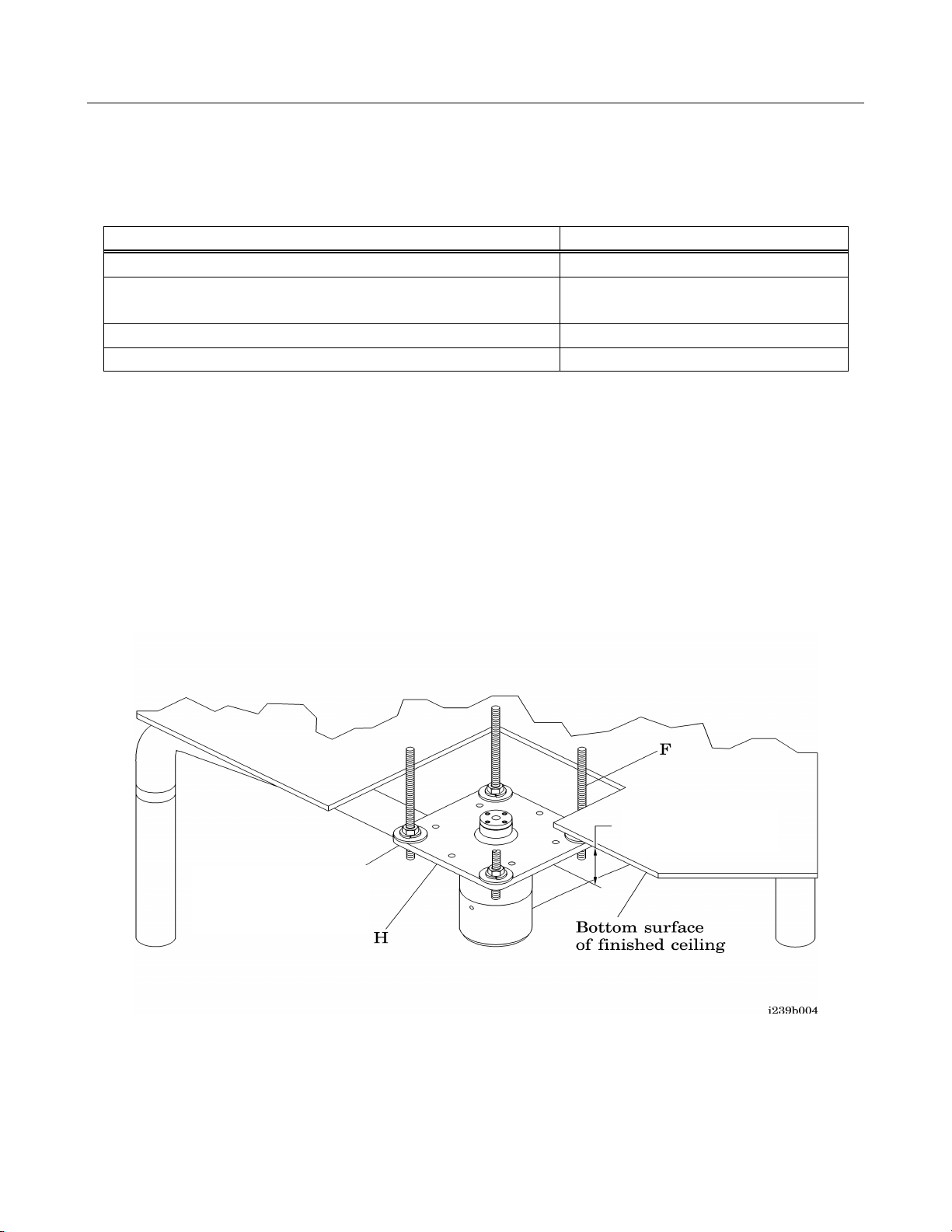
4. Ensure that the suspension arm assembly ceiling base plate (H) will be installed with the bottom
surface 2 1/4" (5.72 cm) below the bottom of the finished ceiling. Or 2 7/8" (7.11 cm) from the
bottom of the finished ceiling to the bottom of the threaded rod (F) to ensure access to the
leveling nuts on both sides of the ceiling base plate (H) (see figure 2.2.1).
Figure 2.2.1. Base Plate Alignment
SIM-S2Z0001 Rev 05 Effective Date 10/25/09
Page 24
- 24 -
7” ( 17.78 cm)
Hole
2.3 Base Plate Alignment Installation
5. Make sure that the studs will protrude no more than 1" (2.6cm) from the bottom surface of the
suspension arm assembly ceiling base plate (H) to allow clearance for the ceiling shroud. The
minimum distance between plates after installation is 4" (10cm), and the maximum distance is
7" (18 cm). The threaded rods must protrude below the finished ceiling by 2 7/8" (7.11 cm)
Figure 2.3.1. Mounting Pattern
NOTE:
When mounting the ceiling base plate to the anchor plate, Nuvo recommends that the installation
contractor use the four slotted bolt pattern holes.
SIM-S2Z0001 Rev 05 Effective Date 10/25/09
Page 25
- 25 -
Suspension Arm Assembly Installation
WARNING:
Use a lift capable of safely raising the suspension arm assembly to the ceiling mounting point.
Failure to use an appropriate lift could result in personal injury or equipment damage.
P
Weights of Suspension systems are: Single 105 lb (47.6 kg)
(without light heads attached) Single – Monitor Ready 135 lb (61.2 kg)
Dual 155 lb (70.3 kg)
Dual – Monitor Ready 185 lb (84 kg)
Triple 205 lb (93 kg)
1. Remove the top cover of the shipping container, and remove the bag of loose hardware.
2. Place the suspension arm assembly (A) (see figure 6) on the portable lift.
3. Install the threaded rods (F) (figure 6) so they protrude below the finished ceiling by 2 7/8" (7.11
cm)
Figure 2.3.2. Suspension Arm Assembly
`
SIM-S2Z0001 Rev 05 Effective Date 10/25/09
Page 26

- 26 -
Suspension Arm Assembly Installation
WARNING:
Follow safety precautions provided by the lift manufacturer when lifting
the suspension arm assembly. Improper operation could result in personal
injury or equipment damage.
WARNING:
Do not work under unsupported lift fixtures. Personal injury could occur.
CAUTION:
The ceiling plate must be level in two directions. Improper operation of the suspension
arm assembly could result in equipment damage.
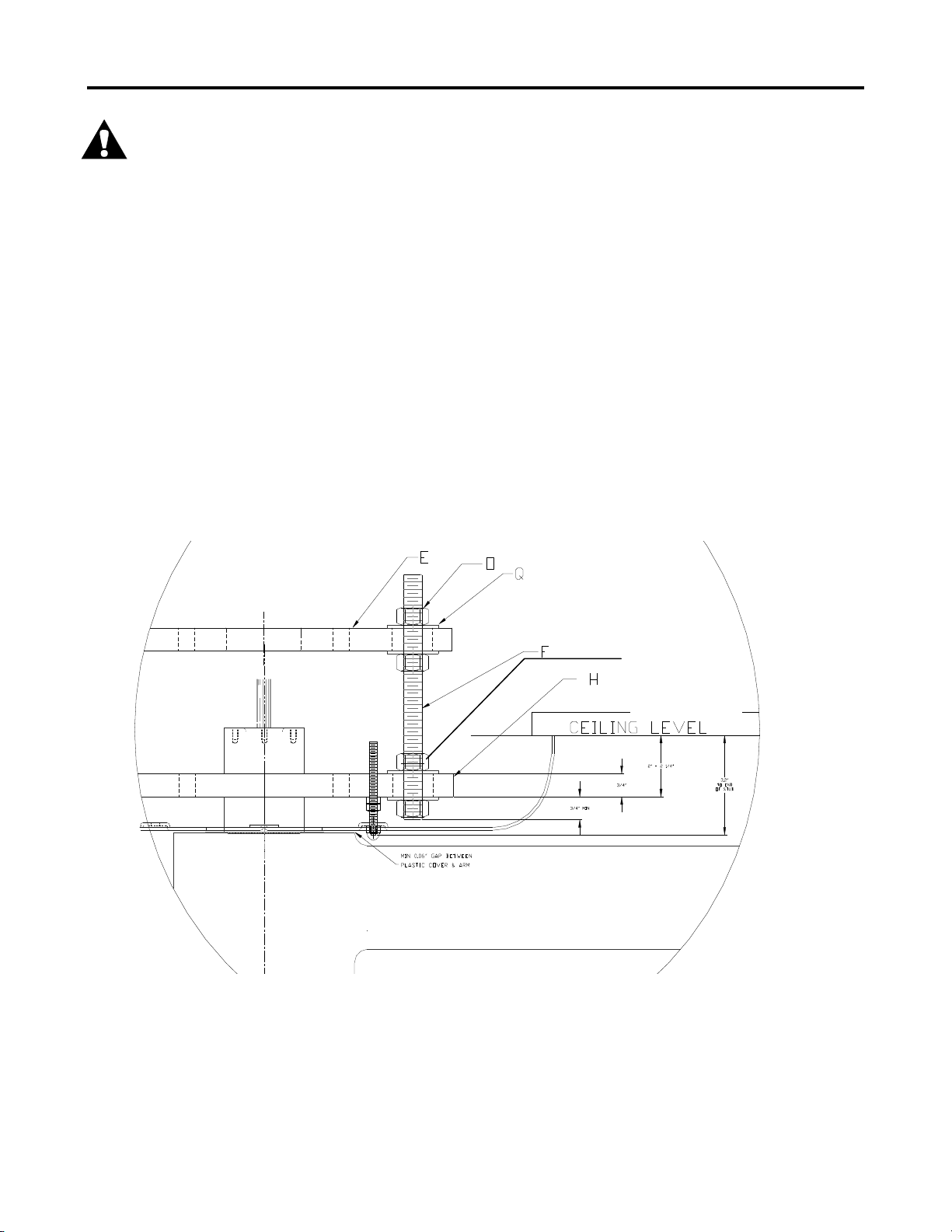
4. Install the serrated flanged nuts (P) (figure 7) on the threaded studs (F) below the field installed
mounting plate.
5. Install the serrated flanged nuts (P) upside down on the threaded studs (F), below the nuts
installed in step 4, flush to the finish ceiling.
6. Raise the suspension arm assembly (A) up to the ceiling.
7. Support the lift with blocks, as needed, while working under the raised suspension arm
assembly (A).
8. Lift the suspension arm assembly (A) until the base plate (H) contacts the flanged nuts.
9. Install the lower washers (Q) and nylon locknuts (O) on the threaded studs (F) to level the
ceiling mounting plate (H).
10. Tighten the nuts (P&O) on the top and bottom of the ceiling base plate (H) and on the top and
bottom of the anchor plate (E) using a pair of ¾” (19 mm) or 15/16” (24 mm) wrenches or
sockets.
Torque to: 80-107 ft-lb (.04-.05 kgf/cm2) for ½″ nuts
160-200 ft-lb (.08-.10 kgf/cm2) for 5/8″ nuts
11. Check the mounting plate (H) for level in two directions (90° from each other) using a
precision level.
12. Adjust and tighten the nuts (O) again, anchoring the suspension arm assembly (A), using a pair
of ¾” (19 mm) or 15/16” (24 mm) wrenches.
13. Make sure the bottom surface of the base plate (H) maintains a distance of 2 1/4 ”
(5 cm) below the finished ceiling line.
14. Remove the blocks under the lift.
15. Remove the lift from under the suspension arm assembly (A)
SIM-S2Z0001 Rev 05 Effective Date 10/25/09
Page 27
- 27 -
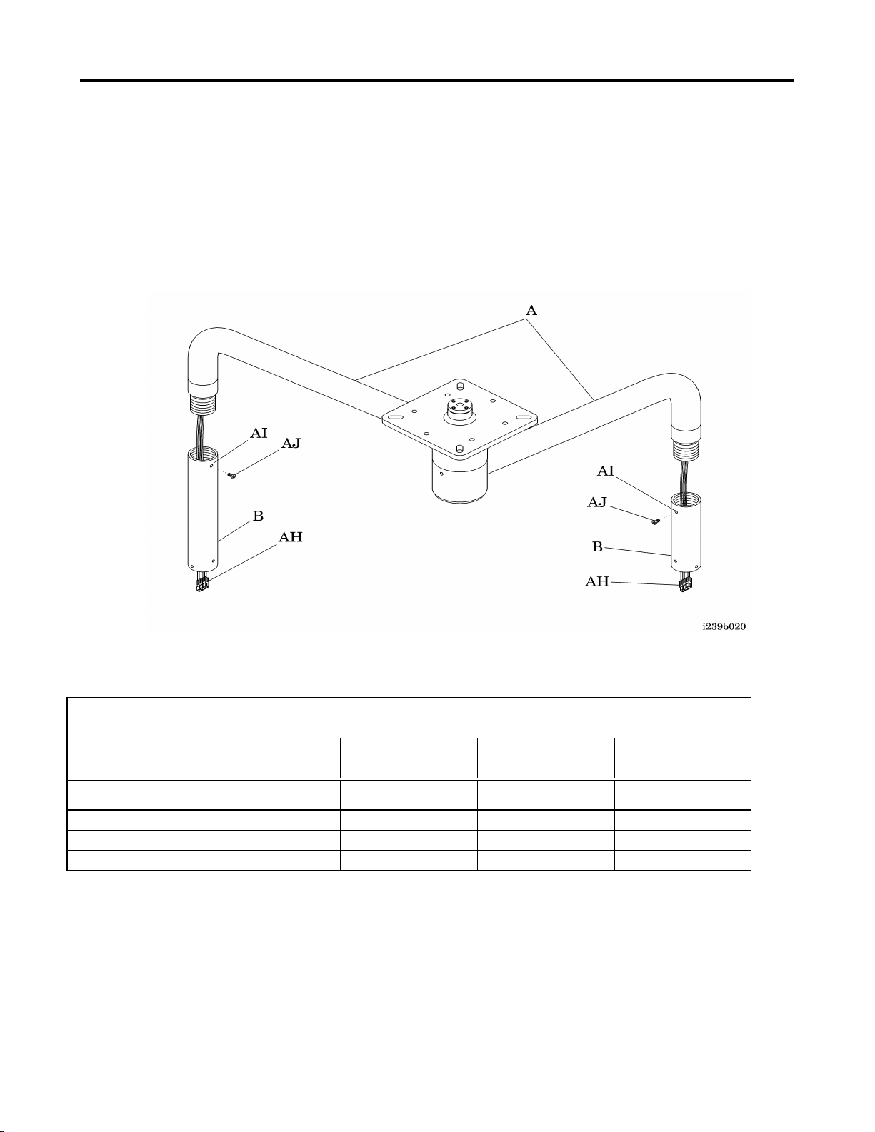
2.4 Vertical Tube Installation
Table 2.4.1. Finished Ceiling Height
Type
8′ 7″(262 cm) -
8′ 11″(272 cm)
9′ 0″(274 cm) -
9′ 4″(284 cm)
9′ 5″(287 cm) -
9′ 9″(297 cm)
9′ 10″(300 cm) -
10′ 2″(310 cm)
Tube Length
Tube Length
Tube length
Tube Length
SINGLE LIGHT
5″(12.7 cm)
10″(25.4 cm)
15″(38.1 cm)
20″(50.8 cm)
DUAL LIGHT
N/A
5″ & 10″
10″ & 15″
15″ & 20″
TRIPLE LIGHT
N/A
N/A
5″,10″ & 15″
10″, 15″ & 20″
The suspension system may have the vertical tubes pre-installed at the Nuvo factory, if this is the case
then this section does not apply.
1. Remove the vertical tubes (B) from the shipping container, and all of the parts included with the
vertical tube kit box (see figure 2.4.1).
Figure 2.4.1. Vertical Tube Installation
2. Ensure that the vertical tubes (B) you are installing are the proper length for the
Nuvo Surgical Light installation that you are performing (see table 2.4.1).
NOTE:
The longest vertical tube should be installed on the suspension arm assembly closest to the ceiling. The
shorter vertical tube should be installed on the suspension arm assembly closest to the floor.
SIM-S2Z0001 Rev 05 Effective Date 10/25/09
Page 28

- 28 -
Vertical Tube Installation
3. Test fit the threads on each vertical tube (B) by temporarily screwing it onto the appropriate
suspension arm assembly (A).
NOTE:
The threads may need to be cleaned if the vertical tubes do not screw onto the suspension arm
assemblies smoothly, and without any binding.
4. Ensure that the wiring (AH) extending from the suspension arm assemblies (A) is long enough
to go through the vertical tube (B), and extend slightly out of the end of the vertical tube (B)
when it is screwed onto the suspension arm assembly (A) all of the way.
5. Screw the vertical tube (B) onto the suspension arm assembly (A) until it bottoms out.
6. Unscrew and back-off the vertical tube (B) until the hole (AI) in the vertical tube (B) lines up
with the threaded hole in the suspension arm assembly (A).
NOTE:
This procedure should give you approximately 1/32” (0.8mm) of clearance between the rotating tube
and the stationary portion of the arm.
7. Test the rotation of the suspension arm assemblies (A), and ensure the arm moves smoothly
without any binding.
SIM-S2Z0001 Rev 05 Effective Date 10/25/09
Page 29

- 29 -
2.5 Ceiling Control / Transformer Box Installation
WARNING:
Ensure that electrical power is removed from the correct branch circuit. Failure to remove
applied power could result in personal injury or equipment damage.
Electrical connections to the ceiling control box to be completed by a certified electrician.
Install the ceiling control / transformer box assembly (U) to the building structure in accordance
with the customer’s specifications (see figure 2.5.1) if not previously installed.
Figure 2.5.1. Ceiling Control / Transformer Box Installation
1. Remove the screws (R) and cover (S) from the junction box (T) using a Phillips head
screwdriver.
2. Remove a knockout on the junction box (T) for the main voltage connection in accordance with
the local codes.
3. Set the associated facility circuit breaker to OFF. Lock out and tag the circuit breaker.
4. Connect the facility wiring conduit (V) to the ceiling control / transformer box (T) in accordance
with the as-built wiring schematic drawings and all required electrical codes.
5. Using the conduit strain relief, secure the incoming wires.
6. Place the cover back on the junction box, and tighten the screws.
SIM-S2Z0001 Rev 05 Effective Date 10/25/09
Page 30

- 30 -
Ceiling Control / Transformer Box Electrical Wiring Installation
Connect the suspension arm assembly wiring (Z) or extension cable if used to connector (W) and,
if applicable, the optional wall control wiring cable (AA) to the connector (Y) on the control box
(X) in accordance with the as-built wiring schematic drawings (see figure 2.5.2).
Figure 2.5.2. Wiring Connections
SIM-S2Z0001 Rev 05 Effective Date 10/25/09
Page 31

- 31 -
A
2.6 Optional Wall Control Box Installation
If included and not pre-installed, install the wall control box following the steps below:
a. Ensure the circuit breaker is still off.
b. Attach the mounting plate to a 2 gang wall box using the supplied screws.
Figure 2.6.1. Mounting Plate
c. Connect the wall control harness from the ceiling control box. Match wire colors as
shown at the side of the blue connector (A) at the bottom left (when looking at the back)
of the pc board or table 2.6.1.
Optional Control Panel Installation
SIM-S2Z0001 Rev 05 Effective Date 10/25/09
Page 32

- 32 -
LIGHT-1
From first terminal to
last
COLOR
TYPE
GAGE
1
RED
BULK 9V (+V)
22
2
RED/BLACK
DC GROUND (grd)
22
3
WHITE/BLACK
SERIAL (ser)
22
LIGHT-2
If installed
4
WHITE
BULK 9V (+V)
22
5
ORANGE/BLACK
DC GROUND (grd)
22
6
ORANGE
SERIAL (ser)
22
LIGHT-3
If installed
7
BLUE
BULK 9V (+V)
22
8
GREEN
DC GROUND (grd)
22
9
GREEN/BLACK
SERIAL (ser)
22
Table 2.6.1. Wire Chart
SIM-S2Z0001 Rev 05 Effective Date 10/25/09
Page 33

- 33 -
Figure 2.6.2. Mounting Control Panel
Onto Mounting Plate
Figure 2.6.3. Attaching Control Panel
with Plastic Screw
Plastic screw
Wall Control Box Installation
b. Install the wall control onto the mounting plate. Raise the top hinged panel and align the two
rectangular holes with the tabs on the mounting plate. Press the panel against the plate and
down. Ensure the control panel is flush. Secure with the plastic screw (figure 2.6.3).
SIM-S2Z0001 Rev 05 Effective Date 10/25/09
Page 34

- 34 -
2.7 Counterbalance Arm Assembly Installation
WARNING:
Use a lift capable of safely raising the counterbalance arm assembly to the suspension
arm assembly. Failure to use an appropriate lift could result in personal injury or
equipment damage.
WARNING:
Follow lifting safety precautions provided by the lift manufacturer when lifting the
counterbalance arm assembly. Improper operation could result in personal injury or
equipment damage.
Do not connect
camera wires on
lower arm
NOTE:
The counterbalance arm assembly and lighthead / yoke assembly are shipped fully assembled and
ready to install.
1. Ensure the circuit breaker is still off.
2. Place the counterbalance arm assembly (C) with the lighthead/yoke assembly (D) on the
portable lift (see figure 2.7.1).
Figure 2.7.1. Counterbalance Arm Assembly
The lighthead and counterbalance arm assembly weighs 55 lb. (23 kg)
SIM-S2Z0001 Rev 05 Effective Date 10/25/09
Page 35

- 35 -
Counterbalance Arm Assembly Installation
WARNING:
Do not work under an unsupported load. Install appropriate temporary supports. Failure
to do so could result in personal injury or equipment damage.
WARNING:
Ensure that electrical power is removed from the facility wiring. Failure to remove
applied power could result in personal injury or equipment damage.
3. Raise the counterbalance arm assembly (C) and lighthead/yoke assembly (D) up to the vertical
tube assembly (B).
4. Support the lift with blocks while working under the raised counterbalance arm assembly (C)
5. Raise the counterbalance arm assembly (C) until it is close enough to attach the wiring.
6. Connect the wiring from the suspension arm assembly (A) to the counterbalance arm assembly
(C) using the keyed plug/connector.
NOTE:
The suspension arm vertical tube mounting holes must align with the mounting holes on the
counterbalance arm clevis to ensure proper installation of the mounting hardware. Rotate vertical tubes
as required.
7. Install the counterbalance arm assembly (C) into the vertical tube assembly (B) by lifting the
lighthead 15◦ toward the ceiling.
8. Install the screws (K) to secure the counterbalance arm assembly (C) to the vertical tube
assembly (B), using the Allen™ wrench set. Light # 1 is the upper-most arm, # 2 is the next
down (if dual), # 3 would be the bottom light (if triple).
9. Install the appropriate decal (AG) around the base of the vertical tube to cover the screws (K).
10. Install the lamps control assembly by inserting two long teather rods into opposite holes in the
lamp assembly and two short thumb screws into the remaining holes.
SIM-S2Z0001 Rev 05 Effective Date 10/25/09
Page 36

- 36 -
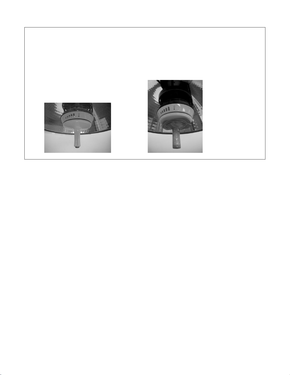
2.8 Voltage Adjustment
1. Remove the tag and lockout on the circuit breaker.
2. Apply power to the Nuvo Surgical Light.
3. Turn on the light to the brightest setting.
4. Remove the sterilizable Control Handle from the lighthead assembly.
5. Using a TRUE RMS multi-meter on the AC setting, measure the voltage at the lighthead
through the test port holes on the bottom of the light assembly (see figure 2.8.1) by inserting the
multi-meter probes into the outer two holes for the primary light.
Figure 2.8.1. Voltage Measurement
NOTE:
Voltage should be between 22.5V and 23.0V for both primary and secondary lamp sockets with the
light at the # 5 (highest) intensity level.
SIM-S2Z0001 Rev 05 Effective Date 10/25/09
Page 37

- 37 -
CAUTION:
Do not change the setting more than one position at a time. Adjusting the voltage more
than one position at a time can cause damage to the lamp and lighthead assembly.
M
Voltage Adjustment
6. If the voltage is within range, proceed to the "Operations Check". If the voltage is not within
range, adjust the voltage as follows:
a. Remove power from light.
b. Remove the cover from the ceiling control / transformer box.
c. Locate the rotary dial (M) on the P.C. board (see figure 2.8.2).
Figure 2.8.2. Board Adjustment
d. Using a jeweller’s screwdriver, turn the rotary dial to a lower number to lower the voltage, or
turn the rotary dial to a higher number to increase the voltage.
Output Voltage Adjustment
0 1 3 4 5 6 7 8 9 A B C D E F
Low High
NOTE:
The rotary dial will “click” into place when changing from one setting to another.
SIM-S2Z0001 Rev 05 Effective Date 10/25/09
Page 38

- 38 -
CAUTION:
Failure to have the proper voltage will result in a shortened life of the lamp, premature
bulb failure, excessive heat, or low light levels. Ensure the proper voltage is at the
lighthead.
Voltage Adjustment
7. When adjusting the voltage, remember that the line voltage will fluctuate with periods of heavy
or moderate usage.
8. Apply power to the light and switch to the brightest intensity.
9. Check the voltage at the lighthead.
10. If the voltage is not within the 22.5V to 23.0V requirements, repeat step D until the voltage
is within limits.
11. If the voltage cannot be adjusted to within limits, contact Nuvo technical support at:
(800) 663-1152.
Repeat steps 1 through 11 for each lighthead.
SIM-S2Z0001 Rev 05 Effective Date 10/25/09
Page 39

- 39 -
2.9 Ceiling Shroud Installation
1. Install the ceiling shroud (L) onto the bottom side of the suspension arm base plate (H) with
threaded rods (J), nuts (I), and plastic acorn nuts (G).
2. When installing the threaded rods (J) and nuts (I), use two nuts on the threaded rod to act as a
locking feature against the bottom of the plate (H). (see figure 2.9.1).
Figure 2.9.1. Ceiling Shroud Installation
SIM-S2Z0001 Rev 05 Effective Date 10/25/09
Page 40

- 40 -
2.1.0 Final Installation Verification
1. Make sure that the distance from the lowest point of the counterbalance arm clevis joint to the
finished floor is approximately 78" (198 cm) to 82″ (209cm) after completion of installation
(see figure 18).
Figure 2.1.0.1. Height Verification
SIM-S2Z0001 Rev 05 Effective Date 10/25/09
Page 41

- 41 -
3.0 Preventive Maintenance
Semi-annual preventive maintenance must be performed by Nuvo personnel to ensure all features are
functioning as originally designed.
Particular attention must be focused on safety features, including but not limited to:
• Lens cleanliness
• Spring force (position force)
• Thumbscrew tightness
• IR filter glass condition
• O-ring integrity
Operational Check
1. Do an operational check of each of the Nuvo Surgical Lights as follows:
a. Push the Hand Control button (on the base of the sterilizable handle) once. The Nuvo
Surgical Light comes on at full intensity, and all five blue LEDs and the lamp indicator
illuminate.
b. Push the Hand Control button again. The light intensity level decreases and one blue LED
goes off every time the button is pushed.
c. Continue cycling the Hand Control button until the light intensity level cycles back to full
intensity, and all five blue LEDs are illuminated.
d. Rotate the Hand Control clockwise to enlarge the light pattern diameter.
e. Rotate the Hand Control counter clockwise to reduce the light pattern diameter.
f. Push the Hand Control button, and hold in for 3 seconds. The Nuvo Surgical Light and all
five LEDs go off.
g. Repeat, as required, for each lighthead.
Operational Check
2. Continue the operational check of the Nuvo Surgical Light as follows:
NOTE:
Less than 4.5 lb (20 N) force, applied to the sterilizable handle is sufficient to move the lighthead
assembly, counterbalance arm assembly, and suspension arm assembly.
a. Pivot the lighthead /yoke assemblies (D) ( figure 14) through the full range of motion. The
lighthead assemblies move quietly and smoothly, without drifting.
b. Raise and lower the counterbalance arm assemblies (C) through the full range of motion.
c. Rotate the suspension arm assemblies (A) 360° through the full range of motion.
3. If the Nuvo Surgical Light fails any of the tests, or requires any type of adjustments, perform
troubleshooting or adjustments in accordance with the service manual.
SIM-S2Z0001 Rev 05 Effective Date 10/25/09
Page 42

- 42 -
4.0 Post-Installation Inspection
1. The installing contractor shall remove all fingerprints and smudges from all exposed surfaces in
accordance with general cleaning procedures.
2. Remove the white tape that covers the joint on each light counterbalance arm.
3. The installing contractor is responsible for checking out the entire installation for proper
operation after hook-up and installation of the Nuvo Surgical Light.
5.0 Maintenance
The lighthead rotates 320° within the yoke and the yoke assemblies rotate 360° continuously. The
interior of the lighthead assemblies is designed to optimize the angle of the light. This reduces
shadowing and delivers cleanly defined color-correct light.
The counterbalance arm assemblies rotate 15° above horizontal and 90° below horizontal at the clevis.
The clevis assembly provides a brake to prevent “free wheeling” of the counterbalance arm and to
provide “touch type motion control.”
The suspension arm assemblies rotate 360° continuously. They differ in length to permit passing
without interference. The vertical tubes rotate 360° continuously and are custom sized to a specific
ceiling height ensuring adequate head clearance.
The wall-control panel provides an additional on/off and intensity control as well as an indicator to
relamp damaged bulbs. Spare bulbs can also be stored in the upper housing compartment. An
individual control box supplies 22.7V AC and 9VDC power to each Nuvo Surgical Light and 9V DC
power to each wall control panel P.C. board.
System Features
The Nuvo Surgical Light features include:
Suspension arms rotate 360° continuous, clockwise, and counterclockwise
Lightheads rotate 320° within the yoke
Yokes rotate 360° continuous, clockwise, and counterclockwise about the
counterbalance arm
Counterbalance arms rotate 15° above horizontal and 90° below horizontal
Lamp control assembly
Light control inside sterile field
Computer modeled reflector
Shadow-free illumination
Excellent color rendition
Low heat output
Back-up lighting
Spare bulb storage in wall control box
Easy to clean and sterilize
SIM-S2Z0001 Rev 05 Effective Date 10/25/09
Page 43

- 43 -
5.1 Operator Interface
Flashing
On-Off
Power applied to lighting system
Both lamps are not working
Figure 5.1.1 Wall Control Panel
SIM-S2Z0001 Rev 05 Effective Date 10/25/09
Page 44

- 44 -
5.2 Electrical System
Lamp Control
Assembly
Figure 5.2.1 Electrical system Block Diagram
SIM-S2Z0001 Rev 05 Effective Date 10/25/09
Page 45

- 45 -
Figure 5.2.2. Transformer Control Box Wiring Diagram
(Dual Light)
SIM-S2Z0001 Rev 05 Effective Date 10/25/09
Page 46

- 46 -
Field wiring terminals (input from hospital)
Connect AC hot (black) to L1
Connect AC neutral (white) to L2
Connect Green or green/yellow safety ground to G.
NOTE:
More recent units destined for North American facilities
are shipped with a power cord with polarized 15A three
prong plug attached.
P16 – Ceiling to wall control
1,2,3 for lighthead #1
4,5,6 for lighthead #2
7,8,9 for lighthead #3
10 for chassis ground (green) shield
1,4,7: +9VDC (red) power to control
2, 5, 8: DC GND (black) (!!!Do not connect to chassis!!!)
3,6.9: serial communication
P24 – Ceiling to lighthead control and lamps
1,2,4,5,6 to lighthead #1
8,9,11,12,13 to lighthead #2
15,16,18,19,20, to lighthead #3
24 for central mount chassis ground (green)
(1,2) (8,9) (15,16): 24V AC to lamps
4,11,18: +9VDC (red) power to lighthead control
5, 12, 19; DC GND (black) (!!! Do not connect to
chassis!!!)
6, 13, 20: Serial communications
Figure 5.2.3 Ceiling Control Connectors
SIM-S2Z0001 Rev 05 Effective Date 10/25/09
Page 47

- 47 -
Each of the three sets of slip rings:
Ceiling pivot, 360° continuous
Outer pivot, 360° continuous
Yoke pivot, 360° continuous
(1,2): 24V AC to lamps
4: +9VDC (red) power to lighthead control
5: DC GND (black) (!!!Do not connect to
chassis!!!)
6: serial communications
(1,5): 24V AC to lamps
6: 9VDC
2: DC GND (!!!Do not connect to chassis!!!)
3: serial
Ceiling
Field wiring terminals
120VAC, 1.6 amps, 180 watts
100 VAC, 2.0 amps, 180 watts
220VAC, 0.9 amps, 180 watts
230-260VAC, 0.8 amps, 180
watts
Main fuse
Power line filter
Intensity regulator
XXXVAC to 24VAC
transformer
P24 (black circular connector)
24 VAC, 8 amps, 180 watts
Ceiling pivot slip ring
Outer pivot slip ring
Yoke pivot slip ring
Lighthead
P8 (blue connector)
Current monitor
Relay switch
Lamp
Backup Lamp
Figure 5.2.4. Slip Rings and Lighthead Control Connector
Table 5.2.1. Lamp Power Flow
SIM-S2Z0001 Rev 05 Effective Date 10/25/09
Page 48

- 48 -
Lamp power flow, 24VAC (slip rings 1,2)(P8-1,5)
(1,2) Lighthead #1
(8,9) Lighthead #2
(15,16) Lighthead #3
Chassis ground (slip ring 3) (P8-8)
Figure 5.2.5. Lamp Power Flow
Electrical Control Power Flow
P24 – Ceiling to Lighthead
P16 – Ceiling to Wall
9VDC (red) (slip ring 4)
P16-1, P24-4 Lighthead #1
P16-4, P24-11 Lighthead #2
P16-7,P24-18 Lighthead #3
DC GND (black) (slip ring 5)
P16-2, P24-5 Lighthead #1
P16-5, P24-12 Lighthead #2
P16-8, P24-19 Lighthead #3
Serial communications (white) (slip ring 6)
P16-3, P24-6 Lighthead #1
P16-6, P24-13 Lighthead #2
P16-9, P24-20 Lighthead #3
SIM-S2Z0001 Rev 05 Effective Date 10/25/09
Page 49

- 49 -
Figure 5.2.2. Transformer Control Box Wiring Diagram, 115 and 230 Volt
Figure 5.2.1. Electrical System Wiring Diagram
Figure 5.2.6. Electrical Control Power Flow
SIM-S2Z0001 Rev 05 Effective Date 10/25/09
Page 50

- 50 -
6.0 Troubleshooting Procedures
WARNING:
Only facility-authorized maintenance personnel should troubleshoot the Nuvo
Surgical Light. Troubleshooting by unauthorized personnel could result in
personal injury or equipment damage.
Getting Started
Begin each procedure in this chapter with step 1. Follow the sequence outlined (each
step assumes the previous step has been completed). In each step, the normal operation
of the product can be confirmed by answering Yes or No to the statement. Your
response will lead to another step in the procedure, a repair analysis procedure (RAP),
or a component replacement. If more than one component is listed, replace them in the
given order.
Start with Initial Actions to begin gathering information about the problem.
Perform the Function Checks to isolate or identify a problem and to verify the repair
after completing each corrective action (replacing or adjusting a part, seating a
connector, etc.)
Perform the Final Actions after the Function Checks to verify the repair.
If troubleshooting procedures do not isolate the problem, call Nuvo Technical Support
at (800) 663-1152 or (814) 899-4220.
SIM-S2Z0001 Rev 05 Effective Date 10/25/09
Page 51

- 51 -
6.1 Initial Actions
Yes
No
Go to “Function Checks” on page 52
Yes
No
Go to “Function Checks” on page 52.
Yes
No
Go to “Function Checks” on page 52.
Use Initial Actions to gather information from operators concerning problems with the Nuvo Surgical
Light. Note symptoms or other information concerning the problem that the operator describes. This
information helps identify the probable cause.
1. Someone who can explain the problem is available.
2. Ask that person to demonstrate or explain the problem. The problem can be duplicated.
Troubleshooting Procedures
3. The problem is a result of improper operator action
4. Perform the “Function Checks” on page 52 to ensure proper operation of the Surgical Light.
SIM-S2Z0001 Rev 05 Effective Date 10/25/09
Page 52

- 52 -
Yes
No
Go to “Initial Actions” on page 51.
Yes
No
Check the building circuit breaker panel, and ensure the applicable
circuit breaker (A) is in ON position (see figure 6.2.1).
6.2 Function Checks
1. Initial Actions have been performed
2. Power is applied to the Surgical Light as indicated by the power-on green LED.
Figure 6.2.1. Standard or Emergency Circuit Breaker Box
SIM-S2Z0001 Rev 05 Effective Date 10/25/09
Page 53

- 53 -
Troubleshooting Procedures
Yes
No
Go to RAP 6.4.
Yes
No
Go to RAP 6.5
Yes
No
Go to RAP 6.6.
Yes
No
Go to RAP 6.7.
Yes
No
Go to RAP 6.8.
Yes
No
Go to RAP 6.9.
Yes
No
Go to RAP 6.0.1.
Yes
No
Go to RAP 6.0.2, 6.0.3, 6.0.4, or 6.0.5
3. The Surgical Light comes on when pushing the button on the Hand Control.
4. The Surgical Light comes on when pushing the button on the wall control.
5. The light intensity level can be adjusted properly from the Hand Control.
6. The light intensity level can be adjusted properly from the wall control.
7. The Surgical Light goes off when pushing and holding the button on the Hand Control for 3
seconds.
8. The Surgical Light goes off when pushing and holding the button on the wall control for 3
seconds.
9. The transformer control box is operating properly.
10. The light does not drift horizontally at the suspension arms, vertically at the counterbalance
arms, or rotationally.
11. Go to “Final Actions” on page 54.
SIM-S2Z0001 Rev 05 Effective Date 10/25/09
Page 54

- 54 -
Troubleshooting Procedures
SHOCK HAZARD:
Use care when checking live voltages. Do not touch live terminals, wires, and
ground. Failure to use caution will cause serious electrical shock injury.
Yes
No
Replace bulbs
Yes
No
Replace fuse
Yes
No
Check the ceiling control internal wiring. Go to RAP 6.0.1
6.3 Final Actions
1. Complete the required preventive maintenance procedures. See “Preventive Maintenance
Checklist” section 3.0.
2. Complete all required administrative tasks.
6.4 Surgical Light Does Not Turn On Using The Hand Control
1. Verify both light bulbs are installed in the lamp control assembly.
2. Check the fuse mounted on the transformer control box. Is fuse in working condition?
3. The Surgical Light operates properly after performing the following procedure:
a. Remove the Lamp Control Assembly. See section 7.0 1&2.
b. Turn the main power off then on. There should be voltage supplied to the
lighthead, but only for a few seconds before it automatically switches off,
therefore, this is a two person procedure.
c. Verify a voltage reading of 14 to 24V AC true RMS within a minimum of 3
seconds at the blue connector (pins 1 and 5) of the lighthead core. (Note:
Voltage range is due to light intensity setting).
SIM-S2Z0001 Rev 05 Effective Date 10/25/09
Page 55

- 55 -
Troubleshooting Procedures
Yes
No
Replace with new lamps. See User Information page 14.
Yes
No
Replace the Lamp Control Assembly.
4. Check the lamps using the following procedure:
a. Remove the Lamp Control Assembly and lamps. See section 7.0 # 1&2
b. Verify the resistance of each lamp is less than 3 ohms.
5. Measure the primary lamp voltage through the access holes in the control
housing using the following procedure: (see section 2.8. figure 2.8.1)
a. Install the Lamp Control Assembly.
b. Verify a voltage reading of 14 to 24V AC true RMS within a minimum of
3 seconds is available for the primary lamp. (Note: voltage range is due to
range of light intensity settings).
c. Verify a voltage reading of zero is available for the back-up lamp.
6. Go to “Final Actions” on page 54.
SIM-S2Z0001 Rev 05 Effective Date 10/25/09
Page 56

- 56 -
Troubleshooting Procedures
SHOCK HAZARD:
Use care when checking live voltages. Do not touch live terminals, wires, and
ground. Failure to use caution will cause serious electrical shock injury.
Yes
No
Check the transformer control box voltages and fuses’.
Go to RAP 6.0.1.
LIGHT - 1
HOLE #
COLOR
TYPE
GA
1
RED
BULK 9V
22 2 RED/B
DC GND
22 3 WHITE/B
SERIAL
22
LIGHT - 2
HOLE #
COLOR
TYPE
GA
4
WHITE
BULK 9V
22 5 ORANGE/B
DC GND
22 6 ORANGE
SERIAL
22
LIGHT - 3
HOLE #
COLOR
TYPE
GA
7
BLUE
BULK 9V
22 8 GREEN
DC GND
22 9 GREEN/V
SERIAL
22
Yes
No
Repair or replace the transformer box to wall control harness
6.5 Surgical Light Does Not Turn On Using the Wall Control
1. The Surgical Light functions properly using the Hand Control
2. Check terminal to confirm insulator is not preventing good wire contact.
3. Check for continuity in the ceiling control to the wall control harness using the
following procedure:
a. Disconnect the ceiling control connector P16 and wall control panel.
b. Continuity exists between pins 1 through 10 (as appropriate for single, dual or
triple lights) of the ceiling control connector P16 and the wall control end of the
wall control harness.
Looking at the terminal strip on the wall counting from 1 at the top to 9 on the bottom:
Table: 6.5.1
SIM-S2Z0001 Rev 05 Effective Date 10/25/09
Page 57

- 57 -
Troubleshooting Procedures
Yes
No
Go to “Function Checks” on page 52.
4. Check for continuity in the internal wall control harness using the following procedure:
a. Verify that there is one wall control P.C. board for each lighthead.
b. Continuity exists between pins 1, 2, and 3 to unit # 1 pins P1-1, 2,
and 3.
c. Continuity exists between pins 4, 5, and 6 to unit #2 pins P1-1, 2, and
3.
d. Continuity exists between pins 7, 8, and 9 to unit #3 pins P1-1, 2, and
3.
e. Verify the cable shield is not connected to any wall control P. C.
boards.
f. Install the ceiling control connector P16 and replace the affected wall
control P.C. board.
5. Go to “Final Actions” on page 54
SIM-S2Z0001 Rev 05 Effective Date 10/25/09
Page 58

- 58 -
Troubleshooting Procedures
SHOCK HAZARD:
Use care when checking live voltages. Do not touch live terminals, wires, and ground.
Failure to use caution will cause serious electrical shock injury.
Yes
No
Replace the Lamp Control Assembly.
Yes
No
Replace the Lamp Control Assembly
6.6 Intensity Level Does Not Adjust Properly Using the Hand Control
1. The Surgical Light primary lamp intensity operates properly after
performing the following procedure:
a. Turn the main power off, then on, and observe the Lamp Control
LEDs.
b. Verify that the primary lamp is on and at least one blue intensity
LED is lit.
c. Verify that the green ready LED is lit.
d. Verify that the yellow relamp LED is off.
e. Verify that the 4 thumbscrews are snug tight locking in the Lamp Control
assembly
2. The Surgical Light primary lamp intensity control operates properly after
performing the following:
a. Press and release the hand Control push button several times
b. Verify the primary lamp intensity changes accordingly.
c. Verify the blue intensity LEDs show the correct intensity level.
SIM-S2Z0001 Rev 05 Effective Date 10/25/09
Page 59

- 59 -
3. The Surgical Light back-up lamp intensity operates properly after
Yes
No
Replace the Lamp Control Assembly.
Yes
No
Replace the Lamp Control Assembly.
performing the following procedure:
a. Lower the Lamp Control Assembly.
b. Remove the primary lamp, and install the Lamp Control Assembly
c. Turn the main power off, then on, and observe the Hand Control
LEDs.
d. Verify that the back-up lamp is on and at least one blue intensity
LED is lit.
e. Verify that the green ready LED is lit.
f. Verify that the yellow relamp LED is lit.
4. The Surgical Light back-up lamp intensity control operates properly after
performing the following:
a. With the primary lamp still removed, press and release the Hand
Control push button several times.
b. Verify that the back-up lamp intensity changes accordingly
c. Verify that the blue intensity LEDs show the correct intensity level.
6. Reinstall the primary lamp
7. Go to “Final Actions” on page 54.
SIM-S2Z0001 Rev 05 Effective Date 10/25/09
Page 60

- 60 -
Troubleshooting Procedures
SHOCK HAZARD:
Use care when checking live voltages. Do not touch live terminals, wires, and
ground. Failure to use caution will cause serious electrical shock injury.
Yes
No
Replace the wall control P.C. board. See section #2.6
Yes
No
Replace the wall control P.C. board. See See section #2.6
6.7 Intensity Level Does Not Adjust Properly Using the Wall Control
1. The Surgical Light primary lamp intensity control operates properly after
performing the following:
a. Turn the main power off, then on, and observe the wall control
LEDs.
b. Verify the primary lamp is on and at least one blue intensity LED is
lit.
c. Verify that the green ready LED is lit.
d. Verify that the yellow relamp LED is off.
2. The Surgical Light primary lamp intensity control operates properly after
performing the following:
a. Press and release the wall control push button several times, and
observe the wall control LEDs.
b. Verify that the primary lamp intensity changes accordingly.
c. Verify that the blue intensity LEDs show the correct intensity level.
d. Verify that the LED pattern is the same on both the wall control and
the lighthead control.
SIM-S2Z0001 Rev 05 Effective Date 10/25/09
Page 61

- 61 -
3. The Surgical Light back-up lamp intensity operates properly after
Yes
No
Replace the wall control P.C. board. See See section #2.6
Yes
No
Replace the Lamp Control Assembly.
performing the following procedure:
a. Lower the Lamp Control Assembly. See section 7.0 #3-7
b. Remove the primary lamp, and install the Lamp Control Assembly.
c. Turn the main power off, then on, and observe the wall control
LEDs.
d. Verify that the back-up lamp is on and at least that one blue intensity
LED is lit.
e. Verify that the green ready LED is lit.
f. Verify that the yellow relamp LED is lit.
4. The Surgical Light back-up lamp intensity control operates properly after
performing the following:
a. With the primary lamp still removed, press and release the wall
control push button several times.
b. Verify that the back-up lamp intensity changes accordingly.
c. Verify that the blue intensity LEDs show the correct intensity level.
d. Verify that the LED pattern is the same on both the wall control and
the lighthead control.
5. Reinstall the primary lamp.
6. Go to “Final Actions” on page 54.
SIM-S2Z0001 Rev 05 Effective Date 10/25/09
Page 62

- 62 -
Troubleshooting Procedures
SHOCK HAZARD:
Use care when checking live voltages. Do not touch live terminals, wires,
and ground. Failure to use caution will cause serious electrical shock injury.
Yes
No
Check the transformer control box’s internal wiring. Go to
RAP 6.0.1.
Yes
No
Replace the Lamp Control Assembly
6.8 Surgical Light Does Not Turn Off Using The Hand Control
1. The Surgical Light primary lamp goes off after performing the following
procedure:
a. Press and hold the Lamp Control Assembly push button for 3
seconds.
b. Verify that the light goes off.
c. Verify that only the green ready LED is lit.
2. The Surgical Light back-up lamp goes off after performing the following
procedure:
a. Lower the Lamp Control Assembly. See section 7.0 # 3-7
b. Remove the primary lamp.
c. Install the Lamp Control Assembly.
d. Press and hold the Hand Control push button for 3 seconds.
e. Verify that the light goes off.
f. Verify that the green ready LED is lit.
g. Verify that the yellow relamp LED remains lit.
3. Install both bulbs, Lamp Control Assembly, and the Sterilizable hand
control.
4. Go to “Final Actions” on page 54.
SIM-S2Z0001 Rev 05 Effective Date 10/25/09
Page 63

- 63 -
Troubleshooting Procedures
SHOCK HAZARD:
Use care when checking live voltages. Do not touch live terminals, wires, and
ground. Failure to use caution will cause serious electrical shock injury.
Yes
No
Replace the wall control P.C. board. See section 2.6
Yes
No
Replace the wall control P. C. board. 2.6
6.9 Surgical Light Does Not Turn Off Using The Wall Control
1. The Surgical Light primary lamp goes off after performing the following
procedure:
a. Press and hold the wall control push button for 3 seconds.
b. Verify that the light goes off.
c. Verify that the green ready LED is lit.
2. The Surgical Light back-up lamp goes off after performing the following
procedure:
a. Remove the Lamp Control Assembly. See “Lamp Control
Assembly” on page 4-6.
b. Remove the primary lamp, and install the Lamp Control Assembly.
c. Press and hold the wall control push button for 3 seconds.
d. Verify that the light goes off.
e. Verify that the green ready LED is lit.
f. Verify that the yellow relamp LED remains lit.
3. Install both bulbs, Lamp Control Assembly, and Sterilizable Hand
Control.
4. Go to “Final Actions” on page 54.
SIM-S2Z0001 Rev 05 Effective Date 10/25/09
Page 64

- 64 -
Troubleshooting Procedures
SHOCK HAZARD:
Use care when checking live voltages. Do not touch live terminals, wires, and
ground. Failure to use caution will cause serious electrical shock injury.
Yes
No
Check downstream wiring and electrical components for
shorts, and replace the fuse.
Nominal Mains Voltage
Measured Voltage
120V
108 to 132V
220V
198 to 242V
230-240V
207 to 264V
Yes
No
Check downstream wiring and electrical components for
shorts, and replace the fuse.
6.0.1 Transformer Control Box Does Not Function Properly
1. Examine the main fuse (4 A, 250V, 3AG, slow blow on 120V boxes) and
(2 A, 250V, 3AG, slow blow on 220 and 230-240V boxes), and measure
resistance, verifying the fuse is good.
2. A voltage reading available at field wiring terminals L1 (hot) and L2
(neutral) as follows:
3. Replace the Ceiling / Transformer Control Box Assembly
4. Go to “Final Actions” on page 54.
SIM-S2Z0001 Rev 05 Effective Date 10/25/09
Page 65

- 65 -
Troubleshooting Procedures
Yes
No
Call Nuvo Technical Support at (800) 663-1152 or (814)
899-4220.
6.0.2 Suspension Arm Drifts Horizontally
NOTE:
The Surgical Light must be completely assembled before any adjustments are
made.
Figure 6.0.2. Suspension Arm Drift
1. Remove the ceiling shroud and using a spirit level check that the mounting plate is horizontal
in all directions (see Suspension Arm Replacement).
2. Adjust the suspension arm brakes (see “Suspension Arm Adjustment”). This solves the
problem.
3. Go to “Final Actions” on page 54.
SIM-S2Z0001 Rev 05 Effective Date 10/25/09
Page 66

- 66 -
Troubleshooting Procedures
Yes
No
Adjust the counterbalance arm spring tension (see
“Counterbalance Arm Adjustment”).
6.0.3 Counterbalance Arm Drifts Vertically
NOTE:
The Surgical Light must be completely assembled before any adjustments are made.
1. The counterbalance arm assembly is at rest after desired positioning (see figure 6.0.3).
Figure 6.0.3. Counterbalance Arm Drift
2. Go to “Final Actions” on page 54.
SIM-S2Z0001 Rev 05 Effective Date 10/25/09
Page 67

- 67 -
Troubleshooting Procedure
Yes
No
Adjust the yoke brake (see 6.0.5 )
6.0.4 Yoke Contains Rotational Drift
NOTE:
The Surgical Light must be completely assembled before any adjustments are made.
1. The yoke assembly is at rest after desired positioning (see figure 6.0.4).
Figure 6.0.4. Yoke Drift
2. Go to “Final Actions” on page 54.
SIM-S2Z0001 Rev 05 Effective Date 10/25/09
Page 68

- 68 -
Troubleshooting Procedures
Yes
No
Adjust the lighthead mounting hardware (see “Lighthead
Assembly Adjustment” 7.5.1 ).
6.0.5 Lighthead Contains Rotational Drift
NOTE:
The Surgical Light must be completely assembled before any adjustments are made
1. The Lighthead assembly is at rest after desire positioning
Figure 6.0.5. Lighthead Drift
2. Go to “Final Actions” on page 54
SIM-S2Z0001 Rev 05 Effective Date 10/25/09
Page 69

- 69 -
SHOCK HAZARD:
To minimize the risk of electrical shock or damage to equipment, disconnect
all electrical power to the system before working on it. Failure to do so could
result in personal injury or equipment damage.
WARNING:
Make sure the lamp control assembly is supported before loosening the four
tether rods. Failure to do so could result in personal injury or equipment
damage.
7.0 Lens Removal
Tools required: 5/64" Allen™2 wrench
Removal
1. Perform the following:
a. Locate the involved building standard/emergency circuit breaker panel.
b. Set the involved circuit breaker (A) to OFF (see figure 6.1.1).
c. Lock out and tag out the breaker.
2. Rotate the sterilizeable handle (A) counterclockwise (see page 14 step 1&2). Remove from
the lamp control assembly (B).
NOTE:
The tether rods will not come out completely, but will drop 3/4" (19 mm) once loosened.
3. Loosen the four tether rods (B) on the lamp control assembly (C).
4. Slowly lower the lamp control assembly (C) evenly until it stops.
5. Continue counterclockwise rotation to free each tether rod from the lighthead assembly, and
remove the lamp control assembly (C).
6. Using the 5/64" Allen™ wrench, remove the trim ring (F), screws (D), mounting
plate (E), and guide plate (G).
7. Remove the screws (H) and the lens (I) from the lighthead housing (J).
SIM-S2Z0001 Rev 05 Effective Date 10/25/09
Page 70

- 70 -
Removal, Replacement, and Adjustment Procedures
Figure 7.0.1 Lens Removal
SIM-S2Z0001 Rev 05 Effective Date 10/25/09
Page 71

- 71 -
Removal, Replacement, and Adjustment Procedures
7.1 Replacement
1. Prepare the new lens (I) for installation as follows:
a. Install new light barrier (K) onto the lens (I) on the opposite side from the (8)
counter bores mounting holes.
b. Assemble the Trim Ring onto the Lens. The lip with the slots goes on the
opposite side of the lens from the counter bore side. Line up slots
approximately centered on each hole of lens, and ensure that stretch of Trim
Ring is evenly distributed around the perimeter.
c. Clean the lens face with P001114 Brillianize anti static cleaner.
2. Install the new lens (I), counterbore side up, on the lighthead housing (J) and
secure the lens with (8) P001096 6-32 x ½ BHC with nylon patch.
3. Install guide plate (G), mounting plate (E), and screws (D) to the lighthead core
(A). Fasten with (4) P000003 6-32 x ½ counter sink screws.
4. Install the lamp control assembly (C), and the four tether rods (B) into the
lighthead assembly.
5. Slowly raise the lamp control assembly (C) up to its original mounting position.
6. Tighten the four tether rods (B) to anchor the lamp control assembly (C).
7. Attach the Hand Control handle (A) to the lighthead assembly and rotate
clockwise until firmly seated.
8. Remove the lockout and out-of-service tags and set the circuit breaker to the ON
position.
SIM-S2Z0001 Rev 05 Effective Date 10/25/09
Page 72

- 72 -
7.2 Counterbalance Arm Assembly
SHOCK HAZARD:
To minimize the risk of electrical shock or damage to equipment, disconnect
all electrical power to the system before working on it. Failure to do so could
result in personal injury or equipment damage.
WARNING:
Do NOT remove the counterbalance arm while it is in the vertical position. The
counterbalance arm is spring-loaded and removing it in the vertical position
could result in personal injury or equipment damage. Refer to Figure 7.2.1
and Figure 7.2.2, below for correct and incorrect removal positioning.
Tools required: Allen™3 wrench set
Portable lift with blocks
Parts required: (1) S2V00080 Number decal (#1)
Or
(1) S2V00081 Number decal (#2)
Or
(1) S2V00082 Number decal (#3)
Removal
NOTE: Removal and installation of the counterbalance arm assembly require 2 individuals, one at the
clevis (knuckle) end of the counterbalance arm and one at the yoke (as in Fig. 7.2.1, below).
Alternatively, an equipment lift may be used.
1. Before removing the counterbalance arm assembly, perform the following:
a. Locate the involved building standard/emergency circuit breaker panel.
b. Set the involved circuit breaker to OFF.
c. Lock out and tag out the breaker.
3
Allen™ is a trademark of Industrial Fasteners, Inc.
SIM-S2Z0001 Rev 05 Effective Date 10/25/09
Page 73

- 73 -
Figure 7.2.1
WARNING:
If using an equipment lift, ensure that lift is capable of safely lowering the counterbalance
arm assembly from the suspension arm assembly vertical tube. Failure to use an
appropriate lift could result in personal injury or equipment damage.
WARNING:
If using a lift, follow lifting safety precautions provided by the lift manufacturer when lifting
the counterbalance arm assembly. Improper operations could result in personal injury or
equipment damage.
WARNING:
Do not work under unsupported lift fixtures. Personal injury could occur
WRONG!
Figure 7.2.2
CORRECT
NEVER Attempt REMOVAL of
COUNTERBALANCE ARM
While It Is In The VERTICAL
POSITION!
SIM-S2Z0001 Rev 05 Effective Date 10/25/09
Page 74

- 74 -
Fig. 7.2.3 Counterbalance Arm Assembly: Clevis / Vertical Tube Juncture
Clevis (knuckle)
Wire Connector
Vertical Tube
Number Decal
Allen™ head screws
Allen™ head screws
Removal, Replacement, and Adjustment Procedures – Counterbalance Arm Assembly
To remove counterbalance arm/lighthead, refer to Figs. 7.2.1 and 7.2.3, and do the following:
Be sure circuit breaker is turned off and ensure power is disconnected from light.
1. Raise light to the highest position and face the lighthead toward the ceiling.
2. Remove the number decal.
3. Remove the four Allen™ head screws (5/16” x 5/8” FHCS; P/N P000405) located
under the number decal.
4. Push up on the yoke and slide the clevis (knuckle) from the vertical tube.
5. Detach the wire connector located at the juncture of the knuckle and vertical tube.
Replacement
To replace counterbalance arm / lighthead refer to Figs. 7.2.1 and 7.2.3, and do the following:
Be sure circuit breaker is turned off and ensure power is disconnected from light.
1. Place counterbalance arm horizontally with the lighthead facing the ceiling.
2. Reattach the wire connector located at the juncture of the knuckle and vertical tube.
3. Insert the counterbalance arm into the vertical tube, ensuring that the wires are not
pinched or damaged.
4. Line up the counterbalance arm holes with those on the vertical tube by rotating the
vertical tube while pushing up on the yoke.
5. Install the four Allen™ screws.
6. Lift up on the yoke, and tighten all the Allen screws. The Allen™ screws will not seat
properly until the yoke is lifted and Allen™ screws are tightened.
7. Turn on the circuit breaker, making sure the light functions properly.
8. If the vertical tube is clean and dry and the light is functioning properly,
place the appropriate number decal over the four Allen™ screws.
SIM-S2Z0001 Rev 05 Effective Date 10/25/09
Page 75

- 75 -
Removal, Replacement, and Adjustment Procedures
7.3 Brakes
Tools required: Allen™4 wrench set
Screwdriver
Step ladder
NOTE:
The Nuvo Surgical Light has five points of adjustment to compensate for drifting.
Suspension Arm Adjustment
1. Prior to making adjustments, confirm that the mounting plate is level.
2. Note that there are two types of adjustment to correct any drifting of the suspension arm
assembly. (See points A & C, Figure 7.3.1, below.)
Figure 7.3.1. Suspension Arm Assembly Adjustment
3. To correct drift occurring at the inner hub of the suspension arm assembly (B), tighten the two
(2) setscrews (A) on each arm by turning clockwise.
4. To correct drift occurring at the outer hub of the suspension arm assembly (B), tighten the
setscrew (C) on each arm, by turning clockwise
4
Allen™ is a trademark of Industrial Fasteners, Inc.
SIM-S2Z0001 Rev 05 Effective Date 10/25/09
Page 76

- 76 -
7.4 Counterbalance Arm Adjustment
Lighthead End of Assembly
A
B
There are two points of adjustment to correct any drifting of the counterbalance arm assembly:
The procedure for these adjustments is explained in numbers 1 through 5(b), below.
1. Remove the access cover (A) from the counterbalance arm assembly (B) as follows:
2. To correct downward drifting of the counterbalance arm assembly, do the following:
Note that spring tensioner nut (C) is located within the arm assembly under access cover (A), as
3. To correct upward drifting of the counterbalance arm assembly, do the following:
SIM-S2Z0001 Rev 05 Effective Date 10/25/09
Step one is to adjust the spring tension.
Step two, if necessary, is to apply the brake.
a. With the counterbalance arm at eye level and lighthead end of assembly positioned to
the left, as illustrated in Figure 7.4.1, below, move access cover (A) toward you over
the arm assembly (B).
b. As you do so, access cover (A) will loosen. Lift (A) upward to remove.
Figure 7.4.1. Counterbalance Arm Assembly Adjustment: How to Remove Cover
With the arm horizontal, and access cover (A) removed (as indicated in 1, above)
tighten the spring tensioner nut (C) by turning it clockwise as viewed from the
lighthead.
indicated in Figure 7.4.2, next page.
With the arm horizontal, loosen the spring tension nut (C) by turning it counter-
clockwise as viewed from the lighthead.
Page 77

- 77 -
C
A
B
˚
D
Figure 7.4.2. View Indicating Tension Nut & Brake Screw in Clevis Assembly
4. Replace access cover (A) as follows:
a. Notice that access cover (A) is equipped with two metal tabs, one larger than the other.
Insert the larger metal tab of access cover (A) into the side of the access cutaway that is
closest to you.
Observe that there is a thin slot just beneath the hull of the access cutaway into which the larger metal
tab will slide as you move the access cover toward you.
b. Having inserted the larger metal tab as indicated above, move access cover (A) away
from you until the smaller metal tab on (A) touches the opposite side of the access
cutaway.
Observe that there is another thin slot just beneath the hull of the access cutaway into which the
smaller metal tab will slide upon depressing the metal tab as indicated below.
c. Using a flathead screwdriver, depress the shorter metal tab on (A) until the tab slips into
the slot just beneath the hull of the access cutaway. Moving access cover (A) away
from you while depressing the tab will facilitate insertion.
NOTE: Take care to maneuver access cover (A) carefully while depressing tab to avoid screwdriver
slipping and causing personal injury or damage to equipment.
5 (a). On units built prior to December 1, 2004, the brake screw (D) is recessed into one side of the
clevis assembly. (See previous page, Figure 7.4.2. and Figure 7.4.4, below)
SIM-S2Z0001 Rev 05 Effective Date 10/25/09
Page 78

- 78 -
To access the brake screw, the lighthead must be lowered to the vertical position.
Brake Screw
Location (both sides)
With the lighthead positioned vertically (as in Figure 7.4.3, below.), do the following:
Observe whether the recessed brake screw is a slotted or a hex screw.
If the recessed brake screw is slotted, use a flathead screwdriver to rotate the brake
clockwise until sufficient friction results to eliminate drift.
If the recessed brake screw is a hex design, use a 3/16” Allen™ Wrench to rotate
the brake clockwise until sufficient friction results to eliminate drift.
Figure 7.4.3: Lighthead (Vertically) Figure 7.4.4: Recessed Brake Screw
SIM-S2Z0001 Rev 05 Effective Date 10/25/09
Page 79

- 79 -
ATTENTION: The yoke adjustment setscrew (E) is:
Recessed BELOW outer hull of arm assembly.
Accessed THROUGH the setscrew hole located UNDER access cover (A ) and
A
E
5 (b).There are two external brakes, one on each side of the outer clevis. (See Figure 7.4.5, below.) To
adjust, do the following:
Position the lighhead vertically as described on previous page.
To provide the required level of friction, tighten both external brakes equally using a 1/4”
Allen™ Wrench,
Figure 7.4.5: Dual Brake Screws (Two Views)
Yoke Assembly Adjustment
There is only one point of adjustment to correct yoke assembly drifting. (See Figure 7.4.6, below).
Correcting yoke drift is accomplished by adjusting a setscrew recessed BELOW the outer hull of the
arm assembly (B), and accessed via the setscrew hole located UNDER access cover (A) NEXT TO the
access cutaway, as illustrated in Figure 7.4.6, below.
Figure 7.4.6. Yoke Assembly Adjustment
1. Remove the access cover (A) from the counterbalance arm assembly (B) as
described under the “Counterbalance Arm Adjustment” section, number 1.
2. Using a 3/32” Allen™ Wrench, tighten the setscrew (E), by turning it clockwise
to correct any rotational drifting of the yoke assembly.
SIM-S2Z0001 Rev 05 Effective Date 10/25/09
Page 80

- 80 -
Removal, Replacement, and Adjustment Procedures
7.5 Lighthead Assembly Adjustment
1. There are two points of adjustment to correct any drifting of the lighthead
assembly (see figure 7.3.1).
Figure 7.5.1. Lighthead Assembly Adjustment
2. Remove the yoke caps (A) from both sides of the yoke assembly (B).
3. Release the lockwasher (C) that is retaining the locknut (D).
4. Tighten the locknut (D), by turning clockwise, to correct any rotational drifting
of the lighthead assembly.
5. Reseat the lockwasher (C) to the retaining locknut (D).
6. Install the yoke caps (A).
SIM-S2Z0001 Rev 05 Effective Date 10/25/09
Page 81

- 81 -
A
B
8.0 Replacement Parts
Service Parts Ordering
Using the parts lists in this manual, identify the part number(s) you require. Find the product/model
number label (A) and serial number label (B) (see figure 8.0.1).
Figure 8.0.1. Product Identification Label Location
Call Nuvo Technical Support at (800) 663-1152 with the following information:
Customer name and location
Purchase order number
Product number
Serial number
Part number(s) and quantities
Whether new parts or factory refurbished parts (when available) are requested
Nuvo also provides a fax number to promptly order parts, request part prices and availability, or follow
up on a service order. The fax number is (814) 899-1410.
SIM-S2Z0001 Rev 05 Effective Date 10/25/09
Page 82

- 82 -
To order parts, a $75.00 minimum will prevent a charge for processing your order.
Terms:
Net 30 days
F.O.B. Erie, PA
Prepaid shipping charges added to invoice
All orders shipped UPS ground unless specified
Address all inquiries to:
Nuvo, Inc.
5368 Kuhl Road
Erie, PA 16510
NOTE:
To eliminate possible delays or incorrect billings, do not return any items without a Return Material
Authorization (RMA) number. When a return is requested, an RMA packet is included with each
order. This packet includes an RMA number, instructions and a shipping label. If an RMA number is
not available, obtain one by phoning Nuvo Technical Support at (800) 663-1152.
SIM-S2Z0001 Rev 05 Effective Date 10/25/09
Page 83

- 83 -
Exchange Policy
The following are Nuvo’s policies for in-warranty and out-of-warranty exchanges.
In-Warranty Exchanges:
In some cases, Nuvo will request that parts/products be returned for inspection. When this occurs, you
are expected to return parts/products within 30 days of the exchange part. If you fail to return the
inoperative parts/products within the 30 day period, Nuvo will invoice your facility for the full selling
price of the parts/products.
NOTE:
The preceding billing procedure pertains only to parts/products that Nuvo requests to be returned.
In some cases, the invoice accompanying the parts will show the full selling price (only for Nuvo’s
internal use). Do not confuse this price with your price.
Do not return any parts without an RMA number. When parts/products have been requested to be
returned, Nuvo will include an RMA packet with the parts/products shipment. If an RMA number is
not available, obtain one by phoning Nuvo Technical Support at (800) 663-1152.
Out-Of-Warranty Exchanges:
You are expected to return the inoperative parts/products within 30 days of receipt of the exchange
part. Nuvo will include an RMA packet with the parts/products shipment. If an RMA number is not
available, obtain one by phoning Nuvo Technical Support at (800) 663-1152. If you fail to return the
inoperative parts/products within 30 days, Nuvo will invoice your facility for the full selling price of
the parts/products. Upon return of the inoperative parts/products, Nuvo will issue a credit for the
discounted price.
SIM-S2Z0001 Rev 05 Effective Date 10/25/09
Page 84

- 84 -
Figure 8.0.2. Lighthead/Counterbalance Arm Assembly
Item
Number
Part Number
Quantity
Description
7
S2A00138
1
Lighthead/yoke/counterbalance arm assembly
9
BSS1508
1
Counterbalance arm cover plate
11
BSS1434 *
2
Outer clevis cap
11
66976 *
2
Outer clevis cap
12
P000405
4
Cap Screw FHCS 5/16" x 5/8"
13
S2V00080
1
Label, “1”
14
S2V00081
1
Label, “2”
15
S2V00082
1
Label, “3”
Table 8.0.1 Lighthead/Counterbalance Arm Assembly
SIM-S2Z0001 Rev 05 Effective Date 10/25/09
Page 85

- 85 -
Table 8.0.2 Suspension Arm Mount Assembly – Curved
Item Number
Part Number
Quantity
Description
1
V1350D1C
or
V1350D2C
or
V1350D3C
1
Single Suspension Assembly
Dual Suspension Arm Assembly
Triple Suspension Arm Assembly
2
P000039
2
Allen™
5
head screw, #10-32 x 1/2"
3
BSS2132
or
BSS2137
or
BSS2142
Or
BSS2146
1
Vertical Tube 5" Used on single suspension with ceiling
heights of 8' 9" to 9' 1"
Vertical Tube 10" Used on Single and Dual suspension with
ceiling heights of 9' 2" to 9' 6"
Vertical Tube 15" Used on Single, Dual, and Triple
suspension with ceiling heights of 9' 7" to 9' 11"
Vertical Tube 20" Used on Single, Dual, and Triple
suspension with ceiling heights of 10' 0"
4
BSS2132
or
BSS2137
or
BSS2142
1
Vertical Tube 5" Used on Dual Suspension with ceiling
heights of 9' 2" to 9' 6"
Used on Triple suspension lower arm with ceiling heights
of 9' 7" to 9' 11"
Vertical Tube 10" Used on Dual and Triple suspension
with ceiling heights of 9' 7" to 9' 11"
Used on Triple suspension lower arm with ceiling heights
of 10' 0"
Vertical Tube 15" Used on Dual and Triple suspension with
ceiling heights of 10' 0"
5
BSS1430
1
Hub cover
6
BSS1698
2
Shroud
7
P000644
8
Rod, threaded 1/4" – 20
8
P000631
4
Nut, hex 1/4" – 20
9
P000624
4
Nut, plastic acorn
5
Allen™ is a trademark of Industrial Fasteners, Inc.
SIM-S2Z0001 Rev 05 Effective Date 10/25/09
Page 86

- 86 -
Parts List
Item
Number
Part Number
Quantity
Description
10
V1350D1S
or
V1350D2S
or
V1350D3S
1
1
1
Single Suspension Arm Assembly
Dual Suspension Arm Assembly
Triple Suspension Arm Assembly
2
P000039
2
Allen™
6
head screw, #10-32 x 1/2"
11
BSS2132
or
BSS2137
or
BSS2142
or
BSS2146
1
1
1
1
Vertical Tube 5" Used on Single Suspension with
Ceiling heights of 8' 7" to 8' 11"
Vertical Tube 10" Used on Single and Dual
Suspension with Ceiling heights of 9' 0" to 9' 4"
Vertical Tube 15" Used on Single and Dual and
Triple Suspension with Ceiling heights of 9'5" to 9'
9"
Vertical Tube 20" Used on Single and Dual and
Triple Suspension with Ceiling heights of 9' 10" to
10' 0"
12
BSS2132
or
BSS2137
or
BSS2142
1
1
1
Vertical Tube 5" Used on Dual Suspension with
Ceiling heights of 9' 0" to 9' 6".
Used on Triple suspension lower arm with ceiling
heights of 9' 5" to 9' 9"
Vertical Tube 10" Used on Dual and Triple
Suspension with Ceiling heights of 9' 5" to 9' 9"
Used on Triple Suspension lower arm with ceiling
heights of 9' 10" to 10' 0"
Vertical Tube 15" Used on Dual and Triple
Suspension with Ceiling heights of 9' 10" to 10' 0"
5
BSS1430
1
Hub cover
6
BSS1698
2
Shroud
7
P000644
8
Rod, threaded 1/4" – 20
8
P000631
4
Nut, hex 1/4" – 20
9
P000624
4
Nut, plastic acorn
Table 8.0.3. Suspension Arm Mount Assembly – Straight Arms
6
Allen™ is a trademark of Industrial Fasteners, Inc.
SIM-S2Z0001 Rev 05 Effective Date 10/25/09
Page 87

- 87 -
Parts List
Part
Number
Quantity
Description
S2A00061
1
Transformer control box assembly, 120V, single light
S2A00062
1
Transformer control box assembly, 120V, dual light
S2A00063
1
Transformer control box assembly, 120V, triple light
S2A00064
1
Transformer control box assembly, 220V, single light
S2A00065
1
Transformer control box assembly, 220V, dual light
S2A00066
1
Transformer control box assembly, 220V, triple light
S2A00067
1
Transformer control box assembly, 230-240V, single light
S2A00068
1
Transformer control box assembly, 230-240V, dual light
S2A00069
1
Transformer control box assembly, 230-240V, triple light
Item
Number
Part Number
Quantity
Description
1
1
S2A00036
or
S2A00073
1
1
Lamp control assembly with button
control
Lamp Control Assembly without button
control
2
S2Q00006
2
Lamp
3
3
S2A00074
or
S2A00137
As Required
As Required
Sterilizable Handle with control button
Sterilizable Handle without control button
Part number S2Q00006
Part number S2A00074
Part number S2X00137
Part number S2X00171
Part number P001114
Consumable Parts
• Lamp Bulbs
• Sterilizable Handle with Control Button
• Sterilizable Handle without Control Button
• Sterile Handle Covers
Supplies
• Anti Static Lens Cleaner
Transformer Control Box Assemblies
Table 8.0.4. Transformer Control Box Assembly
Table 8.0.5. Lamp Control Assembly
SIM-S2Z0001 Rev 05 Effective Date 10/25/09
Page 88

- 88 -
SIM-S2Z0001 Rev 05 Effective Date 10/25/09
Page 89

- 89 -
SIM-S2Z0001 Rev 05 Effective Date 10/25/09
Page 90

- 90 -
9.0
SIM-S2Z0001 Rev 05 Effective Date 10/25/09
Page 91

- 91 -
Diameter @ 50% Illumination
6.3 in (160mm) Minimum
Diameter @ 10% Illumination
3.9 in (100mm) Minimum
Remaining Luminance @1m Small / Large Pattern with 1 mask
5121 / 2789 fc ( 55,122/ 30,021 lx), 33% Min.
Remaining Luminance @1m Small / Large Pattern with 2 mask
5410 / 1875 fc (28,233/ 20,182 lx), 46% Min.
Remaining Luminance bottom of standard tube
11144 / 3691 fc (119,953/39,730 lx), 96% Min.
Remaining Luminance bottom of standard tube with one mask
4821 / 2552 fc (51,893/ 27,470 lx), 41% Min.
Remaining Luminance bottom of standard tube with two mask
5121 / 1758 fc (55,122/ 18,923 lx ), 44% Min.
Warning: It is possible to produces more than 1000 W/m 2 by overlapping the light fields of more than
two (2) lights.
SIM-S2Z0001 Rev 05 Effective Date 10/25/09
Page 92

- 92 -
Ceiling Control / Transformer Installation
Rated Voltage
Rated Current
Single
Rated Current
Double
Rated Current
Triple
Rated
Frequency
100 V~
2.5 A~
5 A~
7.5 A~
50/60 Hz
120 V~
2 A~
4 A~
6 A~
50/60 Hz
220 V~
1.25 A~
2.5 A~
3.75 A~
50/60 Hz
230/240 V~
1 A~
2 A~
3 A~
50/60 Hz
NOTE:
Table 3 shows the mains power requirement for power draw to input voltage and light configuration to
help select the proper facility wiring connections.
Table 3. Power Requirements
SIM-S2Z0001 Rev 05 Effective Date 10/25/09
 Loading...