

Page 1
®
MODEL NV-T3
THREE SOURCE AM/FM TUNER
STAND BY
POWER
SENSOR
(( ))
M M ME E EM M MO O OR R RY Y Y
ON
•
OFF
STEREO
F FM M
8 99 7
. .7 75 0
TUNER 1 TUNER 2
AM
PRESET PRESET PRESETTUNE TUNE TUNE
•
FM
P P PR R RE E ES S SE E ET T T
M MH Hz z
10 7 8
MEMORY MEMORY MEMORY
ON
•
OFF
(( ))
STEREO
AM
•
FM
ON
•
OFF
AM
700.00
AM
•
FM
kHz
TUNER 3
NUVO NV-T3
3-IN-1 AM/FM TUNER
OWNER'S MANUAL
Page 2
Safety Instructions
Caution
Risk of Electric Shock
Do Not Open
CAUTION: TO REDUCE THE RISK OF ELECTRIC
SHOCK, DO NOT REMOVE COVER (OR BACK). NO
USER - SERVICEABLE PARTS INSIDE. REFER
SERVICING TO QUALIFIED SERVICE PERSONNEL.
The lightning flash with arrowhead symbol
within equilateral triangle is intended to
alert the user to the presence of
uninsulated “Dangerous Voltage” within
the product enclosure that may be of
sufficient magnitude to constitute a risk of
electric shock to persons.
The exclamation point within an
equilateral triangle is intended to alert the
user to the presence of important
operating and maintenance (servicing)
instructions in the literature
accompanying the appliance.
WARNING
TO REDUCE RISK OF FIRE OR ELECTRIC SHOCK,
DO NOT EXPOSE THIS UNIT TO RAIN OR
MOISTURE.
8) Ventilation - The unit should be situated so that its
location or position does not interfere with its proper
ventilation. For example, the unit should not be
situated on a bed, sofa, rug, or similar surface that
may block the ventilation openings; or placed in a
built-in installation, such as a bookcase or a cabinet
that may impede the flow of air through the
ventilation openings.
9) Heat - The unit should be situated away from heat
sources such as radiators, stoves, or other
appliances that produce heat.
10) Power sources - The unit should be connected to a
power supply only of the type described in the
operating instructions or as marked on the unit.
11) Power cord protection - Power-supply cords should
be routed so that they are not likely to be walked on
or pinched by items placed upon or against them,
paying particular attention to cords at plugs,
convenience receptacles, and the point where they
exit from the unit.
12) Nonuse periods - The power cord of the unit should
be unplugged from the outlet when left unused for
long periods of time.
13) Object and liquid entry - Care should be taken so
that objects do not fall into or liquids spilled into
the inside of the unit.
1) Read instructions- All the safety and operating
instructions should be read before the unit is operated.
2) Retain instructions - The safety and operating
instructions should be retained for future reference.
3) Heed warnings - All warnings on the unit and in the
operating instructions should be heeded.
4) Follow instructions - All operating and other
instructions should be followed.
5) Water and moisture - The unit should not be used
near water - for example, near a bathtub, washbowl,
kitchen sink, laundry tub, in a wet basement, or near a
swimming pool, etc.
6) Wall or ceiling mounting - Unit should be mounted to a
wall or only as recommended by the
ceiling
manufacturer.
7) Cleaning - The unit should be cleaned only as
recommended by the manufacturer.
14) Servicing - The user should not attempt to service
the unit beyond those means described in the
operating instructions. All other servicing should be
referred to qualified service personnel.
15) Damage requiring service - The unit should be
serviced by a qualified service personnel when:
A. The power supply cord or the plug has been
damaged; or
B. Objects have fallen, or liquid has spilled into the
unit; or
C. The unit has been exposed to rain; or
D. The unit does not appear to operate normally or
exhibits a marked change in performance; or
E. The unit has been dropped, or the cabinet has
been damaged .
16) Power lines - An outdoor antenna should be located
away from power lines.
17) Grounding or polarization - Precautions should be
taken so that the grounding or polarization is not
defeated.
Page 3
For U.S. Models
Note to CATV system installer:
This reminder is provided to call the CATV system
installer’s attention to Section 820-40 of the NEC,
which provides guidelines for proper grounding
and, in particular, specifies that the cable ground
shall be connected to the grounding systems of the
building, as close to the point of cable entry as
practical.
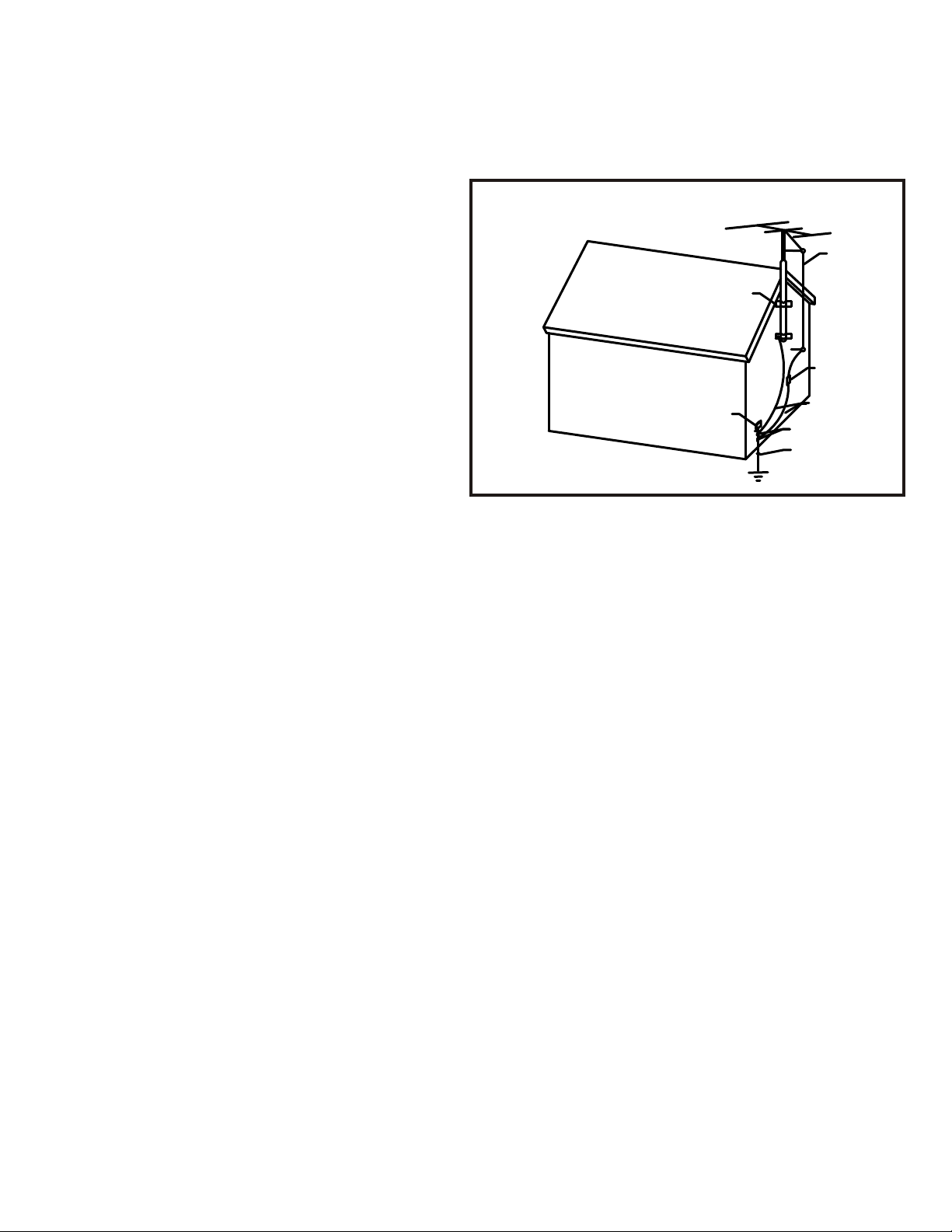
Precautions
GROUND
CLAMPS
ANTENNA
LEAD-IN
WIRE
FCC Information for the User
Caution:
Changes or modifications by the user that are not
expressly approved by the party responsible for
compliance could void the user’s authority to
operate the equipment.
NOTE:
This equipment has been tested and found to
comply with the limits for a class B digital device ,
pursuant to part 15 of the FCC rules. These Limits
are designed to provide reasonable protection
against harmful interference in a residential
installation. This equipment generates, uses and
can radiate radio frequency energy and, if not
installed and used in accordance with the
instructions, may cause harmful interference to
radio communications. However, there is no
guarantee that interference will occur in a particular
Installation. If this equipment does cause harmful
interference to radio or television reception, which
can be determined by turning the equipment off
and on, the user is encouraged to try to correct the
interference by one or more of the following
measures:
1) Reorient or relocate the receiving antenna.
2) Increase the separation between the equipment
and the receiver.
3) Connect the equipment into an outlet on a circuit
different from that to which the receiver is
connected.
4) Consult the dealer or an experienced radio/TV
technician for help.
ANTENNA
DISCHARGE UNIT
NEC SECTION
810-20
ELECTRIC
SERVICE
ENTRANCE
NEC NATIONAL ELECTRICAL CODE
GROUNDING
CONDUCTORS
GROUND CLAMPS
POWER SERVICE
GROUPING ELECTRODE
SYSTEM NEC ART 250
PART H
Warranty
NUVO Technologies warrants this product to be free of defects in
workmanship or materials for a period of three (3) years from the
original date of purchase. This warranty applies to the original
purchaser only and is not transferable. This warranty is subject to
the following conditions and exclusions.
-Defects caused by wear and tear, misuse, or neglect are
not covered by this warranty.
-This warranty will be void if:
a. The unit has been altered or modified.
b. The serial number has been removed or
defaced.
c. Original purchase is not from an Authorized
NUVO Dealer.
d. The warranty card is not completely filled out and
mailed within 10 days of the original purchase.
Neither NUVO Technologies nor NUVO dealers are liable for any
incidental or consequential damages resulting from any defect in or
failure of NUVO Technologies products. This warranty gives the
original owner of NUVO Technologies products specific legal rights,
and he or she may also have other rights which vary from state to
state. This warranty is expressly in lieu of all other agreements and
warranties, expressed or implied, except as may be otherwise
required by law.
Page 4

®
Model NV-T3
3-in-1 AM/ FM Tuner
Introduction
Imagine the capability to enjoy AM news in the den … soft rock FM in the kitchen … and a smooth jazz
FM station in the bedroom … all at the same time and without having to purchase three separate tuners.
With the introduction of the NUVO™3-IN-1 AM/FM tuner, this dream is now a reality.
The NUVO™3-in-1 provides three independent AM/FM tuners in one convenient and affordable package.
Using the handy RC1 remote, you can easily control the 3-in-1 from anywhere in your home.
With separate IR (infrared) codes for each tuner, it’s simple to choose preset stations, adjust volume
levels, switch from AM to FM, mute a specific tuner, and more - all with one remote control.
There’s no need for multiple remotes!
NUVO™
The 3-in-1 Tuner can be used with most any audio system. But when combined with a NUVO™
or Kustom multi-source, multi-zone system, you get complete control, convenience, and flexibility.
That’s the magic of NUVO™.
NUVO™
NUVO™
List of Supplied Accessories Part #
1) One NV-RC1 Remote Control NV-RC1
2) Two AAA Batteries N/A
3) Three Indoor FM Antennas NV-FM1
Table of Contents
Page 1) Front Cover
Page 2) Safety Page
Page 3) Precautions Page
Page 4) Introduction, List of Supplied Accessories, Table of Contents
Page 5) LCD Display
Page 6) Work Sheet
Page 7) Front Panel Controls and Their Functions
Page 8) Remote Control
4) Three Indoor AM Antennas MV-AM1
5) One Power Cord N/A
6) Three Audio Cables NV-AC1
PART #
Page 9) Rear Panel Connections
Page 10) Troubleshooting
Page 11) Remote AM/FM Antenna Configurations
Page 12) Specifications
Page 5

LCD Display
2
3
1
MODEL NV-T3
THREE SOURCE AM/FM TUNER
STAND BY
POWER
SENSOR
M ME EM MO OR RY Y
ON
•
OFF
STEREO
F FM M
8 99 7
. .7 75 0
TUNER 1 TUNER 2 TUNER 3
AM
PRESET PRESET PRESETTUNE TUNE TUNE
•
FM
P P PR R RE E ES S SE E ET T T
M MH Hz z
10 7 8
MEMORY MEMORY MEMORY
))
((
AM
ON
•
•
FM
OFF
))
((
STEREO
4
6
5
MEMORY
AM
ON
•
OFF
7
700.00
AM
•
FM
kH z
8
1) FM
Frequency Modulation
2) Memory
Lights when programming the tuner.
3) Stereo
This display shows the tuner is capable of receiving stereo broadcasts.
If the display reads ((STEREO)), the tuner is receiving a stereo broadcast.
If the display is off, the tuner is in the mono mode and can be changed only from the remote control.
Please refer to page for more information on the remote control.
4) Numerical Display
This display shows to what frequency the tuner is tuned.
5) MHz
Megahertz
6) Preset Numbers
This display shows what preset is currently being used by the tuner.
7) AM
Amplitude Modulation
8) kHz
Kilohertz
Page 6

Important
Please use this work sheet before attempting to program the NUVO NV-T3.
We recommend this web site for radio programming in your area. This will help
filling out your work sheet.
www.radio-locator.com
Filling out your work sheet
Choose AM or FM; fill in the space.
Fill in the frequency space.
Each preset can be AM or FM and the frequency does not have to be in any
particular order.
Programming the tuner for the first time.
Programming from the front panel is recommended. Programming from the
remote control is not recommended. Turn the unit on and power up all three
tuners.
Program one tuner at a time.
1) Press preset until desired preset number is displayed.
2) Choose AM or FM.
3) Tune to desired station by pressing the tune-up or tune-down arrows.
4) Press and hold the memory button until the preset number blinks.
5) Repeat the process for each preset.
Preset
Number
0
1
2
3
4
5
6
7
8
9
10
11
12
13
14
15
16
17
18
19
NUVO Tuner 1 NUVO Tuner 2 NUVO Tuner 3
AM or FM
Station
Frequency
Preset
Number
0
1
2
3
4
5
6
7
8
9
10
11
12
13
14
15
16
17
18
19
AM or FM
Station
Frequency
Preset
Number
0
1
2
3
4
5
6
7
8
9
10
11
12
13
14
15
16
17
18
19
AM or FM
Frequency
Station
Page 7

Front Panel Controls and Their Functions
4
))
((
MODEL NV-T3
THREE SOURCE AM/FM TUNER
STAND BY
POWER
1
SENSOR
2
3
MMEEMMOORRY
ON
•
OFF
5
STEREO
F FM M
8 99 7
. .7 75 0
TUNER 1 TUNER 2 TUNER 3
AM
PRESET PRESET PRESETTUNE TUNE TUNE
•
FM
7
6
P P PR R RE E ES S SE E ET T T
M MH Hz z
10 7 8
MEMORY MEMORY MEMORY
9
8
1) Power Button
Press switch on for stand by power.
This switch was designed to be left on all the time.
2) Stand by LED
Lights when the power switch is engaged.
MEMORY
AM
ON
•
•
FM
OFF
((
STEREO
))
ON
•
OFF
Y
AM
700.00
AM
•
FM
kH z
3) Remote control sensor
This receives signals from the remote control.
4) Display
This shows various information (refer to page 5 for details).
5) On/Off
This turns power on and off for that specific tuner.
6) AM/FM
This changes reception band between AM and FM.
7) Preset
This changes the preset stations.
8) Tune
This button is used for tuning. Press button to tune to higher frequencies. Press
button to tune to lower frequencies.
9) Memory
This button is used to store radio station frequencies. Refer to page 6 for more information.
Page 8

Remote Control Model NV-RC1
TUNER 1
TUNER 2
TUNER 3
SOURCE 1
1
SOURCE 4
4
SOURCE 7
7
NUM
POWER
OFF
MODE
MON
BAND
AM FM
TUNE
-
PRESET
-
TUNER
MULTI-ROOM
SOURCE 2
2
SOURCE 5
5
SOURCE 8
8
SOURCE 10
0
ON
ST
+
+
TUNER
SOURCE 3
SOURCE 6
SOURCE 9
ON-OFF
MUTE
MULTI
ROOM
3
6
9
MEM
ALL
VOL
VOL
MODEL NV-T3
THREE SOURCE AM/FM TUNER
STAND BY
SENSOR
POWER
10m
R
E
M
O
T
E
C
O
N
T
R
O
L
((
)) ((
MMEEMMOORRY
STEREO
M MH Hz z
F FM M
8 99 7
. .7 75 0
TUNER 1 TUNER 2 TUNER 3
AM
ON
PRESET PRESET PRESETTUNE TUNE TUNE
•
•
FM
OFF
MEMORY
P P PR R RE E ES S SE E ET T T
10 7 8
MEMORY MEMORY MEMORY
))
STEREO
AM
ON
•
•
FM
OFF
10 meter maximum
distance
Y
kHz
AM
700.00
AM
ON
•
•
FM
OFF
KEY
POWER OFF
POWER ON
MODE MONO
MODE ST
BAND AM
BAND FM
TUNE +
TUNE PRESET +
PRESET -
NUM
0 THRU 9
MEM
RC-1 Tuner remote
Function
This turns tuner off
This turns tuner on
Selects FM mono
Selects FM stereo
Selects AM band
Selects FM band
Tunes up in frequency
Tunes down in frequency
Advances presets forward
Advances presets backward
Numeric Display
Selects a tuner preset 1
through 20 with “0” = 1st
preset and “19” = last
preset.
Programs selected
stations in selected
presets
This button is for direct tuning.
Example: If 97.7 FM is the desired station, press NUM
and then press 977 in that order.
Press “0” through “9”
To select presets 0 through 9,
press 11 through 19 and that
preset will be displayed.
See page 6.
Page 9

Rear Panel Connections
TUNER 3 TUNER 2 TUNER 1
ANTENNA ANTENNA ANTENNA
FM 75V
AM LOOP
GND AM GND AM GND AM
AUDIO
OUTPUT
L L LR R R
FM 75V
AM LOOP
AUDIO
OUTPUT
FM 75V
AM LOOP
AUDIO
OUTPUT
IR
EXTERNAL
IR INPUT
MODEL NV-T3
THREE SOURCE AM/FM TUNER
120V ~ 60Hz 12W
KUSTOM INC. CINCINNATI, OH USA
CAUTION
RISK OF ELECTRIC SHOCK
DO NOT OPEN
AVIS: RISQUE DE CHOC ELECTRIQUE-NE PAS OUVRIR
WARNING: SHOCK HAZARD - DO NOT OPEN.
2
1
3
4
1) FM Antenna connection
75-ohm cable connections.
If using an outdoor antenna (not supplied), do not connect the supplied indoor antenna.
If using a 300-ohm cable, a 300-ohm to 75-ohm antenna adapter must be used (not included).
2) AM Antenna connection
AM loop antenna connection.
If using an outdoor AM antenna, also connect the loop antenna for better performance.
3) Audio out
Connect RCA-type audio cables from the tuner to the amplifier.
Connect white to the left channel; connect red to the right channel.
4) IR (Infrared) external connection
IR input connection for external equipment
(This is typically used with a NUVO multi-room audio system.)
Refer to specifications for more information.
5
5) AC power connection
IEC-type power cord connection to AC wall outlet.
Only connect to voltage specified on the back of tuner!
Page 10

Troubleshooting
SYMPTOM CAUSE REMEDY
Noisy reception
Crackling sounds.
Stereo indicator (( ))
flickers.
FM Stereo reception is noisy.
There is distortion and clear
FM
reception cannot be obtained
even with a good antenna.
Cannot tune station
using automatic tuning, no
stereo operation
Noise from other electrical
equipment, ignition noise
from passing vehicles.
Insufficient antenna input.
Transmitter too far away,
antenna is not in direct line
of sight with transmitter
tower.
Multipath interference.
Station is too weak.
The tuning mode is set to
manual tuning.
The FM antenna should be
put up as high as possible.
Install a noise suppressor on
the equipment causing the
noise.
Try using a directional
antenna.
Check all antenna
connections. Try using a
directional antenna. Use
manual tuning.
Try different antenna
positions.
Use manual tuning mode .
Try using a directional.
antenna.
Preset stations can no
longer be tuned in.
Cannot tune station using
automatic tuning.
There are continuous
crackling and hissing noises.
AM
There are buzzing and
whining noises (especially in
the evening).
The T-3 has been unplugged
for a long period of time.
No AC power at the wall
outlet for a long period of
time.
Weak signal.
These noises result from
certain atmospheric
conditions. All types of
electrical equipment cause
noise in AM reception.
A TV set is in use nearby.
Another station is interfering
with the received station.
Reprogram the tuner.
Use manual tuning mode.
Use an outdoor antenna and
a good ground wire.
Note: It is very difficult to
eliminate all noise.
Relocate the NV-T3 or the
TV.
Page 11

Remote AM / FM Antenna configurations
Remote FM antenna:
If using remote antenna,
do not connect supplied
FM antenna. Follow all
connection procedures on
the precautions page
(page 3.)
Three separate remote FM antennas can be used (one for
each tuner). This type of installation is used for directional
antenna placement. Example: Three distance FM towers
located in different directions from the location of the NV-T3.
Static discharge
grounding block.
Earth Ground
In line amp
In-line FM Amplifier (optional)
should be installed as close to
the antenna as possible.
Sound quality will depend on
area and distance from the
station’s tower.
3-way FM splitter
AM loop antennas
must be
connected.
MODEL NV-T3
THREE SOURCE AM/FM TUNER
120V ~ 60Hz 12W
KUSTOM INC. CINCINNATI, OH USA
CAUTION
RISK OF ELECTRIC SHOCK
TUNER 3 TUNER 2 TUNER 1
ANTENNA ANTENNA ANTENNA
FM 75V
AM LOOP
GND AM GND AM GND AM
r
e
t
it
pl
s
y
wa
3
AUDIO
OUTPUT
L L LR R R
FM 75V
AM LOOP
AUDIO
OUTPUT
FM 75V
AM LOOP
AUDIO
OUTPUT
IR
EXTERNAL
IR INPUT
DO NOT OPEN
AVIS: RISQUE DE CHOC ELECTRIQUE-NE PAS OUVRIR
WARNING: SHOCK HAZARD - DO NOT OPEN.
Length of wire:
Experiment for best
reception.
Follow all connection
procedures on the
precautions page
(page 3.)
Recommended Parts
1) Outdoor FM antenna..............................TERK® FM PRO (includes in-line amplifier)
2) 3-way splitter..........................................Any brand that will pass 88 to 108 MHz
3) Static Discharge Grounding Block.........Any brand
Page 12

Specifications*
FM Section
Tuning Range .............................................87.5 to 108 MHz
IF Frequency .............................................10.7 MHz
Usable Sensitivity, 30 dB S/N .....................13 dB
Auto Scan Sensitivity...................................23 dB
IF Rejection.................................................72 dB Max.
Image Response.........................................45 dB Max.
AM Rejection...............................................44 dB AM 60dB/M/30/% Modulation
Limiting Sensitivity.......................................55 dB REF. I/P/-3 db
Frequency Response..................................12HZ to 13.1kHz REF. I/P/-3
Harmonic Distortion.....................................0.01%
Strong Signal Distortion...............................0.39%
AF Output....................................................430mV
Noise, Hum..................................................150mV Max.
Modulation Hum..........................................42 dB
Stereo Indicator...........................................30 dB (Just on)
Channel Separation.....................................35/34 dB
AM Section
Tuning Range ..............................................520 to 1710 kHz
IF Frequency ..............................................450 kHz
Usable Sensitivity, 20 dB S/N ......................60 dB/M
Auto Scan Sensitivity....................................66 dB/M
IF Rejection..................................................48 dB Max.
Image Rejection...........................................17 dB Max.
Frequency Response...................................50HZ to 12.1kHz REF. I/P/-3
Harmonic Distortion......................................0.5% 94dB/M
Strong Signal Distortion................................1.1% 94dB/M / 80% Modulation
AF Output.....................................................1200mV 94dB/M / 80% Modulation
Noise, Hum..................................................3.8mV Max.
Modulation Hum...........................................43dB
Audio Section
Output level/Impedance (fixed)
FM (100% Modulation 1kHz) .......................900mV/2.2k-ohms
AM (30% Modulation 1kHz) .........................150mV/2..2k-ohms
Infrared Section
Input Voltage.................................................3-15 Volts
Input Carrier Frequency................................40 kHz nominal
Polarity..........................................................Active High
General
USA and Canada Models............................120V, 60HZ
Power Consumption.....................................12W
Memory Backup..........................................72 hours
Dimensions(W x H x D)................................430x95x340mm
(16-15/16”x3-3/4”x13-3/8”)
Weight..........................................................4.8kg (10.6 lb)
*Specifications subject to change without notice.
NUVO TECHNOLOGIES · 4940 DELHI PIKE · CINCINNATI OHIO ·
TEL: 1-866-796-4904 FAX: 1-800-451-4944
www.nuvotechnologies.com
E-mail: sales@nuvotechnologies.com
·
45238
0234
 Loading...