

Page 1
NV-T2FAM-EX
Dual AM/FM Tuner
Installation Guide
Page 2

Page 3
ENGLISH
IMPORTANT SAFETY INSTRUCTIONS
Danger
Exposure to extremely high noise levels may cause a permanent
hearing loss. Individuals vary considerably to noise induced hearing
loss but nearly everyone will lose some hearing if exposed to sufficiently
intense noise for a sufficient time. The U.S. Government's
Occupational Safety and Health Administration (OSHA) has specified
the following permissible noise level exposures:
DURATION PER DAY (HOURS) 8 6 4 3 2 1
SOUND LEVEL (dB) 90 93 95 97 100 103
According to OSHA, any exposure in the above permissible limits could
result in some hearing loss. Ear plugs or protectors in the ear canal or over
the ears must be worn when operating this amplification system in order to
prevent a permanent hearing loss. If exposure in excess of the limits as
put forth above, to insure against potentially harmful exposure to high
sound pressure levels, it is recommended that all persons exposed to
equipment capable of inducing high sound pressure levels, such as this
amplification system, be protected by hearing protectors while this unit is in
operation.
CAUTION
RISK OF ELECTRIC SHOCK
DO NOT OPEN
CAUTION: TO REDUCE THE RISK OF ELECTRIC SHOCK, DO
AVIS: RISQUE DE CHOC ELECTRIQUE-NE PAS OUVRIR.
THIS SYMBOL IS INTENDED TO ALERT THE USER TO THE PRESENCE
OF NON-INSULATED "DANGEROUS VOLTAGE" WITHIN THE
PRODUCT'S ENCLOSURE THAT MAY BE OF SUFFICIENT MAGNITUDE
TO CONSTITUTE A RISK OF ELECTRIC SHOCK TO PERSONS.
THIS SYMBOL IS INTENDED TO ALERT THE USER TO THE PRESENCE
OF IMPORTANT OPERATING AND MAINTENANCE (SERVICING)
INSTRUCTIONS IN THE LITERATURE ACCOMPANYING THE UNIT.
APPARATUS SHALL NOT BE EXPOSED TO DRIPPING OR SPLASHING
AND THAT NO OBJECTS FILLED WITH LIQUIDS, SUCH AS VASES,
SHALL BE PLACED ON THE APPARATUS.
NOT REMOVE CHASSIS. NO USER-SERVICEABLE
PARTS INSIDE. REFER SERVICING TO QUALIFIED
SERVICE PERSONNEL.
1. Read all safety and operating instructions before using this
product.
2. All safety and operating instructions should be kept for future
reference.
3. Read and understand all warnings listed on the operating
instructions.
4 . Follow all operating instructions to operate this product.
5. This product should not be used near water, i.e. Bathtub,
sink,swimming pool, wet basement, etc.
6. Only use dry cloth to clean this product.
7. Do not block any ventilation openings, It should not be placed flat
against a wall or placed in a built-in enclosure that will impede the
flow of cooling air.
8. Do not install this product near any heat sources ;such
as,radiators, heat registers, stove or other apparatus (including
heat producing amplifiers) that produce heat.
9. Do not defeat the safety purpose of the polarized or groundingtype plug. A polarized plug has two blades with one wider than the
0ther.A grounding-type plug has two blades and a third grounding
prong. The wide blade or the third prong are provided for your
safety If the provided plug does not fit into your outlet, consult an
electrician for replacement of the obsolete outlet.
10. Protect the power cord being walked on or pinched, particularly at
Plugs, convenience receptacles and the point where they exit
from the apparatus. Do not break the ground pin of the power
supply cord.
11 . Only use attachments specified by the manufacturer.
12. Use only with the cart, stand, tripod, bracket, or table specified by
the manufacturer or sold with the apparatus. When a cart is used,
use caution when moving cart/apparatus combination to avoid
injury from tip-over.
13. Unplug this apparatus during lightning storms or when unused for
long periods of time.
14. Care should be taken so that objects do not fall and liquids are
not spilled into the unit through the ventilation ports or any other
openings.
15. Refer all servicing to qualified service personnel. Servicing is
required when the apparatus has been damaged in any way;
such as, power-supply cord or plug is damaged, liquid has been
spilled or objects have fallen into the apparatus, the apparatus
has been exposed to rain or moisture, does not operate normally
or has been dropped.
16. WARNING: To reduce the risk of fire or electric shock, do not
expose this apparatus to rain or moisture.
Page 4
FRENCH
Danger
L‘exposition a des niveaux eleves de bruit peut provoquer une perte
permanente de l’audition, Chaque organisme humain reagit
differemment quant a la perte de l’audition, mais quasiment tout le
monde subit une diminution de I’acuite auditive lors d’une exposition
suffisamment longue au bruit intense. Les autorites competentes en
reglementation de bruit ont defini les expositions tolerees aux niveaux
de bruits:
DURE EN HEURES PAR JOUR 8 6 4 3 2 1
INIVEAU SONORE CONTINU EN dB 90 93 95 97 100 103
Selon les autorites, toute exposition dans les limites citees ci-dessus,
peuvent provoquer certaines pertes d’audition. Des bouchons ou
protections dans l’appareil auditif ou sur l’oreille doivent etre portes lors
de l’utilisation de ce systeme d’amplification afin de prevenir le risque
de perte permanente de l’audition, Dans le cas d’expositions
superieures aux limites precitees il est recommande, afin de se
premunir contre les expositions aux pressions acoustiquese I evees
potentielIement dangeure u ses, aux personnes exposees aux
equipements capables de delivrer de telles puissances, tels ce
systeme d’amplification en fonctionnement, de proteger l’appareil
auditif.
ATTENTION
RISQUE DE CHOC ELECTRIQUE
NE PAS OUVRIR.
ATTENTION: AFIN DE LlMlTER LE RISQUE DE CHO ELECTR/QUE, NE
CE SYMBOLE A POUR BUT D'AVERTIR L'UTILISATEUR DE LA PRESENCE
DE VOLTAGE DANGEREUX NON-ISOLE A L'INTERIEUR DE CE PRODUIT
QUI PEUT ETRE DE PUISSANCE SUFFISAMMENT IMPORTANTE POUR
PROVOQUER UN CHOC ELECTRIQUE AUX PERSONNES.
CE SYMBOLE A POUR BUT D'AVERTIR L'UTILISATEUR DE LA PRESENCE
D'INSTRUCTIONS D'UTILISATION ET DE MAINTENANCE DANS LES
DOCUMENTS FOURNIS AVEC CE PRODUIT.
AFIN DE REDUIRE LES RISQUÉ D'INCENDIE ET DE DECHARGE
ELECTRIQUE, NE PAS EXPOSER CET APPAREIL A LA PLUIE OU A
L'HUMIDITE.
PAS ENLEVER LE CHASSIS. NE CONTIENT PAS DE
PIECES POUVANT ETRE REPAREE PAR L’UTILISATEUR.
CONFER LE SERVICE APRES-VENTE AUX
REPARATEURS
IMPORTANTES INSTRUCTIONS DE SECURITE
1. Lire avec attention toutes les recommandations et précautions
d'emploi avant d'utiliser ce produit.
2. Toutes les recommandations et précautions d'emploi doivent être
conservées afin de pouvoir s'y reporter si nécessaire.
3. Lire et comprendre tous les avertissements énumérés dans les
précautions d'emploi.
4. Suivre toutes les précautions d'emploi pour utiliser ce produit.
5. Ce produit ne doit pas être utilisé près d'eau, comme par exemple
baignoires, éviers, piscine, sous-sol humides ... Etc.
6. Utiliser exclusivement un chiffon sec pour nettoyer ce produit.
7. Ne bloquér aucune ouverture de ventilation. Ne pas placer le
produit tout contre un mur ou dans une enceinte fernée, cela
gênerait le flux d'air nécessaire au refroidissement.
8. Ne pas placer le produit près de toute source de chaeur telle que
radiateurs, arrivées d'air chaud, fourneaux ou autres appareils
générant de la chaleur (incluant les amplificateurs producteurs
de chaleur) .
9. Ne pas négliger la sécurité que procure un branchement polarisé
ou avec raccordement à la terre, Un branchement polarisé
comprend deux fiches dont l'une est plus large que l'autre. Un
branchement à la terre comprend deux fiches plus une troisième
reliée à la terre. Si la fiche secteur fournie ne s'insert pas dans
votre prise de courant. consulter un 'électricien afin de remplacer
votre prise obsolète.
10. Protéger le cordon d'alimentation de tout écrasement ou
pincement, particulièrement au niveau des fiches, des
réceptacles utilisés et à l'endroit de sortie de l'appareil. Ne pas
casser la fiche de terre du cordon d'alimentation.
11. Utiliser uniquement les accessoires spécifiés par le constructeur.
12. Utiliser uniquement avec le chariot de transport, le support, le
trépied, la console ou la table spécifiés par le constructeur ou
vendus avec l'appareil. Lors de l'utilisation d'un chariot, bouger
avec précaution l'ensemble chariotlappareil afin d'éviter les
dommages d'un renversement.
13 Débrancher cet appareil lors d'orages ou s'il n'est pas utilisé
pendant une longue période.
14. Des précautions doivent être prises afin qu'aucun objet ne tombe
et qu'aucun liquide ne se répande à l'intérieur de l'appareil par
les orifics de ventilation ou n'importe quelle autre ouverture.
15. Pour toutes interventions techniques s'adresser à un technicien
qualifié.L'intervention technique est nécessaire lorsque l'appareil
a été endommagé de n'importe quelle façon, comme par
exemple si le cordon secteur ou sa fiche sont détériorés,si du
liquide a coulé ou si des objets sont tombés à l'intérieur de
l'apparei1,si l'appareil a été exposé à la pluie ou à l'humidité, s'il
ne fonctionne pas normalement ou s'il est tombé.
16. ATTENTI0N:Pour réduire le risque d'incendie ou de choc
electrique ne pas exposer l'appareil à la pluie ou à l'humidité.
Page 5
GROUND
CLAMPS
ELECTRIC
SERVICE
ENTRANCE
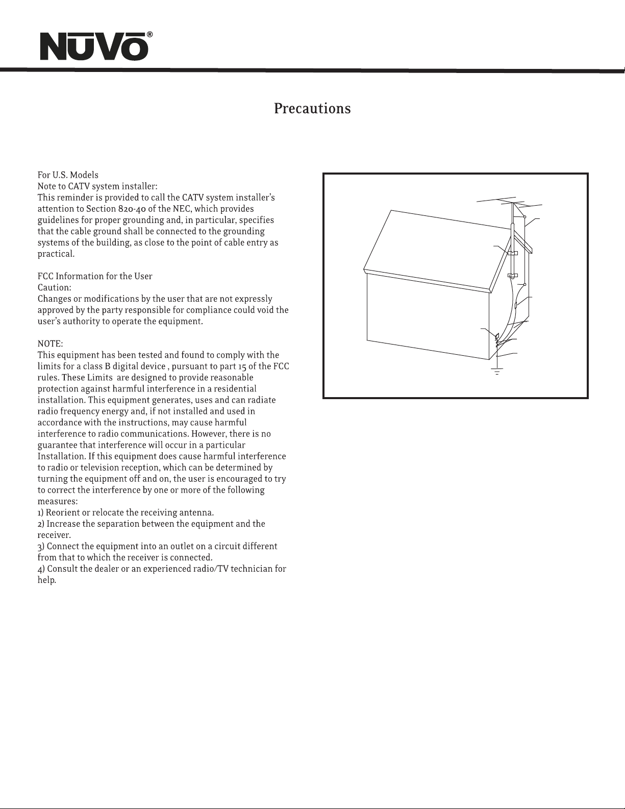
NEC NATIONAL ELECTRICAL CODE
ANTENNA
LEAD-IN
WIRE
ANTENNA
DISCHARGE UNIT
NEC SECTION
810-20
GROUNDING
CONDUCTORS
GROUND CLAMPS
POWER SERVICE
GROUPING ELECTRODE
SYSTEM NEC ART 250
PART H
Page 6
Introduction
Congratulations on your purchase of the NuVo T2 Dual Tuner. Enjoying broadcast music throughout the home has moved into the
st
21 century with NuVo’s T2 Dual Tuner solutions. The included active AM/FM antenna provides a clear precise signal to the home.
The T2’s internal NuVoNet communication allows for very unique and complete feedback to all of the NuVo Control Pads including
RDS (Radio Data Service) artist and song information.
With NuVo, broadcast music has never been better.
Table of Contents:
T2FAM-EX Quick Setup Guide for Use with NuVoNet page 2
Basic Features
Front Panel page 4
Back Panel page 5
NV-T2RC4 Remote Control page 6
I. Installing the T2FAM-EX in the Home
Connecting the Audio Outputs page 7
Setting the Audio Outputs for NuVoNet or
Standalone use page 7
AM/FM Antenna Installation page 8
Connecting for NuVoNet Use page 8
IR Control of the T2FAM-EX page 8
RS232 Serial Control page 9
II. T2FAM-EX Front Panel Menu
Bands page 9
T2FAM-EX Options page 9
Edit Presets page 9
Tuning Mode page 10
T2FAM-EX Settings page 10
Operating Mode page 10
Enabled Bands page 10
Tuning page 10
Diagnostics page 11
Reset Memory page 11
III. NuVoNet Control of the T2FAM-EX
Tuning Up and Down page 12
Changing Bands page 12
Tuning Modes page 12
Selecting Tuner A or B page 12
Control Pad Main Menu page 13
IV. Using the T2 Configurator Software
1.0 Start page 15
2.0 Config page 15
3.0 Presets page 17
Advanced Settings
4.0 Advanced Config page 18
5.0 Update System page 20
NV-T2FAM-EX Specifications page 21
1
Page 7
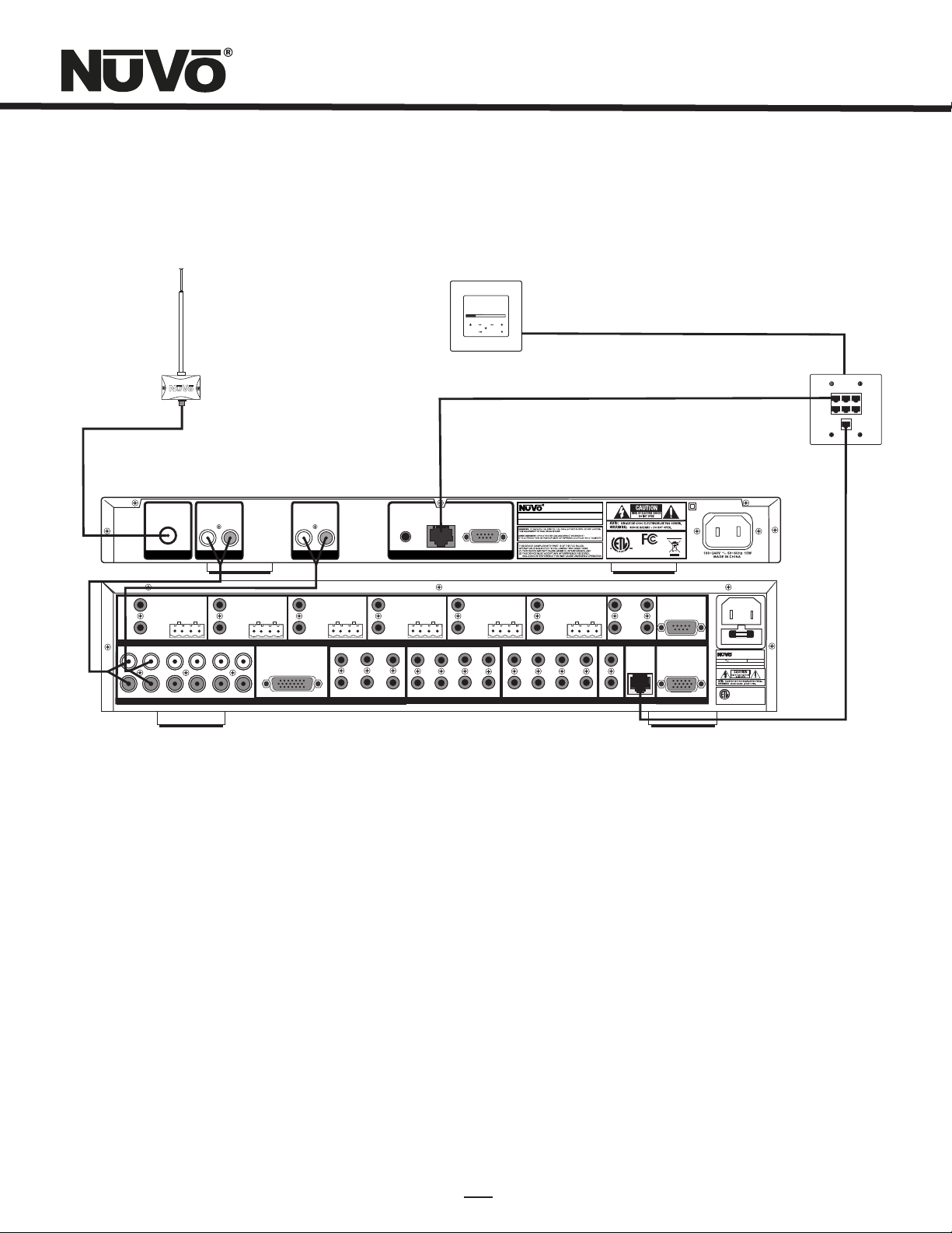
T2FAM-EX Wiring Diagram
AM/FM
Modern Rock
Drift-Follow Th
Living For
MENU
3:09 pm
OK
Concerto EZ Port
Model NV-I8GEZP
Device 2 Device 3
Device 1
Device 4 Device 5 Device 6
Connect to
NV-I8GM
NuVo Technologies LLC He bron , Kentu cky USA
www.nuvotechnolog ies .com
USE NV-T2 DAA WITH
OPTION AL NV-T2 FXC
AND SIRI US ANTEN NA
IN
L
OUTPUT POWER
20W/6OHM X2
L
R
SOURC E INPUT S
TUNE R A
ANTE NNA
VARIABL E
OUTPUT
TIP=L
RING=R
FIXED
OUTPUT
ZONE 1
1 2 3 4 5
L
R
1 2 3 4 5
AUDI O
ZONE 2
R
VARIABL E
OUTPUT
TIP=L
RING=R
FIXED
OUTPUT
L
R
OUTPUT POWER
6
6
20W/6OHM X2
CONNEC T TO
NV-I8X
USE NV-SL C1
CABLE
SOURC E LINK
L
TUNE R B
ZONE 3
AUDI O
VARIABL E
OUTPUT
TIP=L
RING=R
FIXED
OUTPUT
R
OUTPUT POWER
20W/6OHM X2
1
4
SOURC E STATUS INP UTS
NuVoNe t
SYST EM
2 3
ZONE 5
VARIABL E
OUTPUT
TIP=L
RING=R
FIXED
OUTPUT
RS 232
www.nuv otech nolog ies.c om
VARIABL E
OUTPUT POWER
20W/6OHM X2
4
8
OUTPUT
OUTPUT POWER
TIP=L
20W/6OHM X2
RING=R
FIXED
OUTPUT
ZONE 6ZO NE 6
1 2 3
4
EMITT ER OUTP UTS DIGITA L LINK
SUM1
SUM2
5
6
EXT. MUTE
SYSTE M
SYS ON
R
T
E
E
T
N
I
3033118
VARIABL E
OUTPUT
TIP=L
RING=R
OUTPUT
ZONE 7& 8
K
CM
FIXED
CONNEC T TO
NV-I8EZ P1
USE NV-NC 1
NETWO RK
CONFORMS TO UL
STD.6006 5 CERTIF IED
TO CAN/CSA STD .
C22.2 No.6 0065:0 6
CABLE
RoHS
RS-23 2
PROGR AM
CONNEC T TO
NV-I8X
USE NV-SL C1
CABLE
IR INPU T
VARIABL E
OUTPUT
OUTPUT POWER
20W/6OHM X2
TIP=L
RING=R
FIXED
OUTPUT
ZONE 4
2
3
1
5
6
5 6 7
ZONE TR IGGER O UTPUT S
Model N V-T2FAM -EX
Dual SIR IUS Rea dy AM/FM Tun er
NuVo Techn ologi es LLC Heb ron, KY US A •
0728
USE CNLY WITH 250V FUSE
MODEL NV-I8DM
SIX SOURCE EIG HT ZONE
AUDIO DISTRI BUTIO N SYSTE M
120V 60Hz 50 0W
FUSE:T5 A
NuVo Technolog ies Cin cinna ti Ohio U SA
www.nuvot echno logie s.com
CONFORM S TO
R
UL STD.650 0
US
C
CERTIFIE D TO
CAN/CSA ST D.E60 065
3033118
Diagram shown using the Grand Concerto System
T2FAM-EX Quick Setup Guide for Use With NuVoNet
The T2FAM-EX Dual Tuner is the perfect broadcast music solution for whole-home audio. The internal NuVoNet capability of the
T2FAM-EX allows it to easily communicate in real time with the NuVo Grand Concerto and Essentia E6G Control Pads. The following
is a step-by-step guide for setting up and installing the T2FAM-EX for use with the Grand Concerto and Essentia NuVoNet Suites.
Step 1: Upon unpacking your T2FAM-EX Tuner, establish what audio inputs, 1-6, the T2’s A and B audio outputs will represent. Plug
the T2 into an AC power source.
Step 2: Attach the audio outputs A and B of the Tuner to the appropriate numbered inputs on the Grand Concerto or Essentia
System.
Step 3: Connect the CAT5 from the NuVoNet output on the rear panel of the Tuner to one of the Device inputs on the Grand Concerto
EZ Port or the Essentia Allport. This will enable communication to the System’s Control Pads. Note that a single CAT5 connection
provides information from both tuners A and B. A final CAT5 Connection should then be made to the NuVoNet CAT5 input on the
back panel of the Grand Concerto or Essenita main amplifier for the NuVoNet RJ45 on the Grand Concerto EZ Port or the Essentia
Allport. This completes the necessary connection for the NuVoNet communication.
2
Page 8

Step 4: Complete the antenna connection on the back panel of the Tuner using standard RG6 coaxial cable. Quad shielded cable is
recommended. When the antenna is connected, the Tuner will begin receiving a signal for both Tuners A and B.
Step 5: When the Tuner is plugged into an AC power source the front panel display will move through a boot procedure. When this
procedure is complete a message, Uninitialized State Detected will appear.
Step 6: Following the prompt from the display, touch the OK button on the Tuner’s front panel control. This will display a regional
tuning selection, USA and Canada, Western Europe, Australia, and New Zealand. Make to appropriate selection to match the Tuner s
geographic location.
Step 7: Touching OK on the front panel controls will prompt a second screen on the display. This will read, Set Tuner A Mode,
Standalone, Source 1, Source 2, Source 3, Source 4, Source 5, and Source 6. The top selection, Standalone, will be highlighted. This
choice is used for any purpose that is not NuVoNet communication. Using the down arrow on the far right of the front panel
controls, scroll to the desired source input number, and touch OK to select. The display will automatically go to Tuner B setup.
Repeat the steps for setting Tuner A. If NuVoNet is not connected or all available sources have been assigned, then the source
selections will be grayed out.
Step 8: When the desired source number is selected, the display will return to the first screen. Both outputs A and B will display
the lowest AM band frequency by default. At this point full tuning capability can be done from the Tuner’s front panel, or an
addressed NuVo Control Pad.
Step 9: When both Tuner outputs are set, make sure the NuVoNet CAT5 connection between the Tuner s back panel and the
system EZ Port is complete.
The T2FAM-EX Tuner is now ready for NuVoNet communication with either the Grand Concerto or Essentia E6G distributed audio
systems.
Please see the complete installation guide for understanding the full use of your T2FAM-EX Tuner.
3
Page 9
STANDBY
NV-T2FAM-EX
Dual AM/FM Tuner
AM 550
FM 103.5
Ticket To Ride
P103
ST
P104
MENU
BAND
A/B
DISP
OK
RADIO DATA SYSTEM
1 4
2
3
5
6
7
9
8
10
11
12
14
13
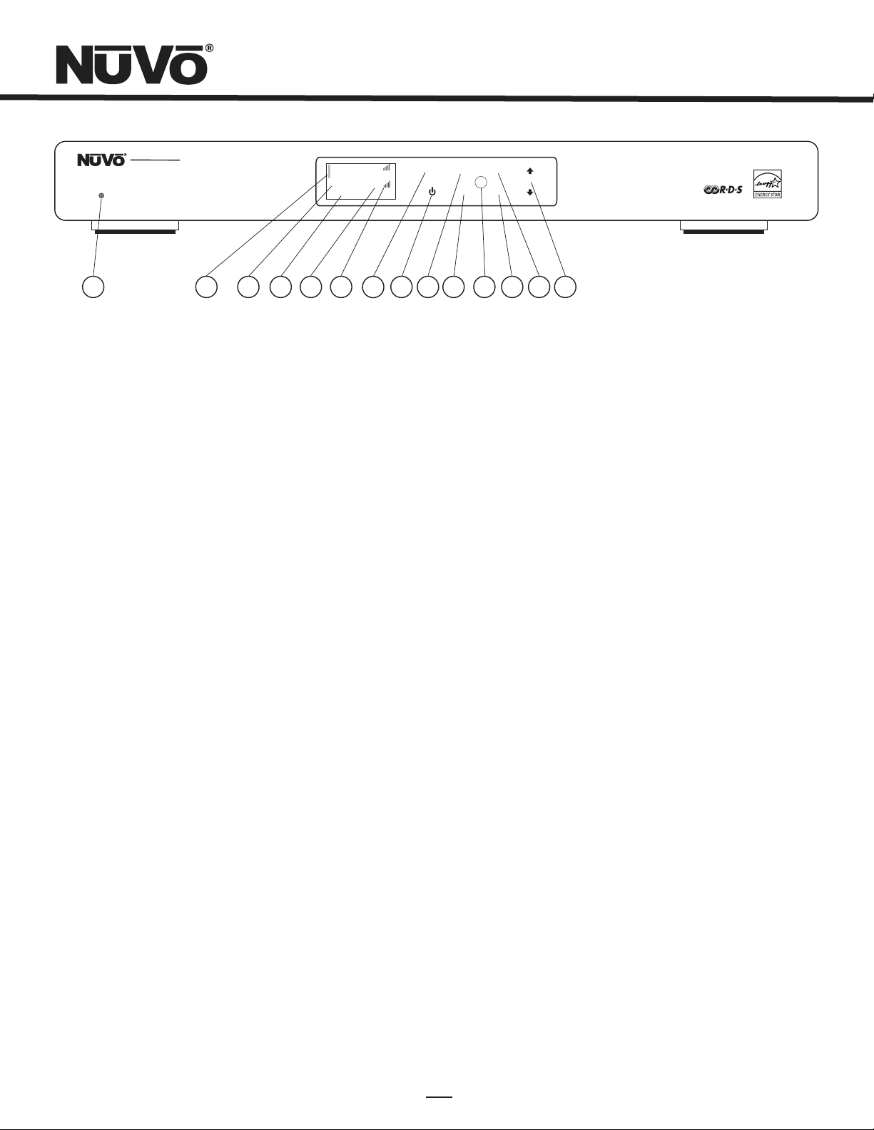
Front Panel Features
1. Standby: This blue LED will light when the T2FAM is plugged into an AC power outlet.
2. Tuner Highlight: This highlight bar shifts between the tuner A and B display to indicate which tuner is being controlled.
3. Broadcast Band Display: This line of the front panel display shows the selected broadcast band and frequency. The bands
available are FM and DAB.
4. Metadata Display: This line of the display scrolls RDS, Radio Data Service, information for FM broadcast.
5. Preset Number: The T2FAM features up to 5 banks of 20 presets each. This indicates the number of the preset bank and the
selected preset.
6. Antenna Signal: The level of signal level is indicated with up to five bars, five being the best. When listening to FM, full stereo
reception is indicated with an abbreviated ST.
7. Menu: This capacitive touch panel allows front access to the T2FAM’s controls as well as preset listening selections and
tuning parameters.
8. Power: This button turns the power for the front panel off when tapped, and causes a soft reboot of the operating system when
it is held for 3 seconds.
9. A/B: By tapping the A/B button, the highlighted tuner output control toggles between A and B.
10. Band: The Band button toggles between AM and FM listening.
11. IR Window: The T2FAM-EX can be controlled via IR through its front panel IR receiver.
12. OK: Ok initiates a highlighted Menu choice.
13. Disp: This button is only active for SIRIUS Satellite radio. It does not function on the T2FAM Tuner.
14. Up and Down Arrows: These arrow buttons provide multiple functions depending on the mode of the tuner. In normal
operation they initiate tuning up and down through the selected band. When in menu mode they scroll
up and down through the menu choices.
4
Page 10

USE NV-T 2FAA
ANTEN NA
IN
ANTE NNA
AUDI O
L
TUNE R A
Mode l NV-T2FA M-EX
Dual SI RIUS Re ady AM/F M Tuner
R
AUDI O
L
TUNE R B
R
IR INP UT
NuVoN et
RS 232
SYST EM
NuVo Tech nolog ies LLC Hebr on, KY USA •
www.nu votec hnolo gies. com
3033118
R
T
E
E
T
K
N
I
CM
CONFORM S TO UL
STD.600 65 CERT IFIED
TO CAN/CS A STD.
C22.2 No. 60065 :06
RoH S
0728
1
2
3
4
5
6
Back Panel Features
1. Antenna Input: This single F connector is the coaxial cable connection between the T2FAM-EX and the included NV-T2FAA
AM/FM antenna.
2. Audio Output: The audio broadcast for AM and FM received by the Tuner module is available through this stereo RCA output.
Tuner A and B offer independent audio outputs for use with the NuVo audio systems or third
party receivers and amplifiers.
3. IR Input: The T2FAM-EX offers a single stereo mini, 3.5mm, connection for independent IR control of both tuners A and B.
4. NuVoNet: This single CAT5 connection provides full NuVoNet communication for both tuners A and B to the NuVo Grand Concerto
and Essentia E6G audio distribution systems. This connection is made at the Grand Concerto EZ Port or the Essentia
E6G Allport.
5. RS232: This DB9 9-pin connector is used for configuration programming (see Section IV. Using the Tuner Configurator Software,
pg. 15) and bidirectional serial control from a third party home automation controller.
6. AC Power: The T2FAM-EX is designed to plug into any AC power source. The digital switching power supply allows the tuner to
respond to any world wide voltage.
5
Page 11

8
NV-T2RC4 Remote Control
TUN E
BAND
A/B
TUNER
9
1
PWR
2
3
4
P
5
6
7
C
DI SP
1
4
7 8
PRE
FM
DAB
T2 Tuner
NV-T2RC4
REMOTE CONTROL
P
C
10
3
2
5
6
9
OK
0
AM
SAT
11
12
13
1.Power: The power button turns the selected tuner on and off.
2.Tune Buttons: These buttons are the equivalent of using the Up and Down arrows on the front panel of the T2FAM-EX to
tune.
3.Band: This button toggles through the tuner s available broadcast bands.
4.Seek Up and Down: The seek buttons will tune to the next available station with the required signal strength for AM and
FM use. The signal threshold can be adjusted higher or lower using the Tuner Configurator software
(see Section IV. Using the Tuner Configurator Software, pg. 18), or through the advanced menu options
on the front panel (see Section II. T2FAM-EX Front Panel Menu, Seek Thesholds, pg. 11).
5.Preset Tune: These buttons step through the assigned presets. The T2FAM-EX is capable of 5 banks of 20 presets.
6.Category Tune: Category Tune is not implemented on this model.
7. Pre: This button is used to establish a preset bank and preset number for the frequency being displayed on the selected
tuner.
8.Tuner A & B LED: This LED glows red when Tuner A is selected and green when Tuner B is selected. This LED glows only
momentarily when a button is pushed.
9.A/B: This button toggles between Tuner A and Tuner B operation.
10.Disp: This button functions only for North American satellite radio use.
11.Numeric Buttons: These buttons (0-9) are used to access a specific station frequency.
12. OK: This is a select button used for saving presets or entering an AM or FM frequency.
13. Source Buttons: These four buttons are a direct select for the tuning bands available through the T2 Tuners. Actual
functionality depends on the model tuner being controlled.
6
Page 12

I. Installing the T2FAM-EX in the Home
Connecting the Audio Outputs (Fig. 1)
The T2FAM-EX has two independent audio outputs labeled A
and B. These are standard stereo RCA connections and can be
connected to any device designed to receive an analog stereo
audio signal.
Setting the Audio Outputs for NuVoNet or Standalone use
(Fig. 2)
The outputs A and B are individually set from the front panel
display of the T2FAM-EX. When the tuner is initially plugged
into an AC power source, a short setup wizard will appear on
the display. A message, Uninitialized State Detected (Press
OK) will appear. When OK is pressed, the prompt is to select a
regional tuning standard. The choices are USA/Canada,
Western Europe, Australia, and New Zealand. Use the Up and
Down arrows to highlight the appropriate choice and touch the
OK button to select. Once regional tuning has been selected,
the display will prompt for the use of each output A and B.
+Output A will highlight automatically. Using the Up and
Down arrows on the front panel, move the highlight to the
appropriate use of the tuner output and touch OK. The choices
are Stand Alone, Source 1, Source 2, Source 3, Source 4, Source
5, and Source 6. For any use other than with the Essentia E6G
or Grand Concerto Systems, select Stand-alone. This will
require IR or serial control of the T2FAM-EX’s functions.
Highlighting the appropriate Source number input for the NuVo
system and touching the OK button sets NuVoNet
communication. Once Output A is set, the highlight will move
to Output B. For operation, both outputs A and B must be set as
Stand Alone or as a NuVoNet Source.
When the Tuner’s outputs are set, they will return to AM 530, or
the minimum AM band setting for the selected regional tuning
parameters. At this point the T2FAM-EX is ready for either
NuVoNet communication or standalone use, depending on the
setting made for both outputs.
Fig. 1
Fig. 2
Uninitialized
State Detected
(Press OK)
Regional Setup
US and Canada
Western Europe
Australia
Set TunerA Mode
Standalone
Source 1
Source 2
USE NV-T2FA A
ANTENNA
IN
ANTEN NA
VARIABLE
OUTPUT
SPEAKER
40W/6 OHMS X 2
TIP=L
LEFT RIGHT
RING=R
FIXED
OUTPUT
ZONE 1
1 2 3 4 5
L
L
R
R
1 2 3 4 5
SOURCE I NPUTS
MENU
MENU
MENU
AUDIO
L
TUNER A
ZONE 2
VARIABLE
CONNECT TO
NV-I8X
USE NV-SLC1
CABLE
SOURCE L INK
ZONE 3
VARIABLE
DISP
OK
DISP
OK
DISP
OK
AUDIO
R
L
TUNER B
VARIABLE
OUTPUT
SPEAKER
40W/6 OHMS X 2
TIP=L
LEFT RIGHT
RING=R
FIXED
OUTPUT
1 2 3
4
SOURCE S TATUS
SPEAKER
OUTPUT
40W/6 OHMS X 2
TIP=L
LEFT RIGHT
RING=R
FIXED
OUTPUT
ZONE 4
6
5
R
OUTPUT
SPEAKER
40W/6 OHMS X 2
TIP=L
LEFT RIGHT
RING=R
FIXED
OUTPUT
6
L
R
6
A/B
BAND
A/B
BAND
A/B
BAND
7
Page 13

AM/FM Antenna Installation (Fig. 3)
The T2FAM-EX is shipped with the NV-T2FAA active AM/FM
antenna. The antenna is designed to work actively with the
tuner using standard 75-ohm coaxial cable. Quad-shielded
cable is recommended for this purpose. The advantage of the
active antenna technology is the remote location capability, up
to 200 feet from the T2FAM-EX location without the need for
an external power supply. The termination at the antenna and
tuner is a standard F style connector. No software
application or configuration is necessary beyond making the
cable connection at each end.
Fig. 3
The NuVo active
antenna can be located up
to 200 feet from the
T2FAM-EX Tuner.
USE NV-T2 FAA
ANTENN A
AUDIO
IN
SIRIU S
R
L
L
AUDIO
SIRIU S
R
Note, for best results, the T2FAA antenna should be located as
high as possible, either in an attic or outside. If you choose to
use a third party antenna, other than the T2FAA, you must use
the forced off setting from the menu to allow the signal to pass
through to the T2FAM-EX, (see Section II. T2FAM-EX Front Panel
Menu, Antenna Power, pg. 11).
Connecting for NuVoNet Use (Fig. 4)
Once audio outputs A and B are set for NuVoNet, the T2FAM-EX
is ready to communicate in real time with the Grand Concerto
or Essentia E6G audio distribution systems. To complete the
connection, all that is necessary is a single CAT5 cable from the
NuVoNet output on the T2FAM-EX’s back panel to one of the
Device inputs on either the Grand Concerto EZ Port or the
Essentia E6G Allport. Since the outputs of the Tuner must be
set as a specific source number input for NuVoNet
communication, the number of the Device connection used is
irrelevant to the system’s operation. Once the connection is
complete, the tuner is ready to fully communicate with
NuVoNet.
Fig. 4
ANTE NNA
TUNE R A
TUNE R B
IR Control of the T2FAM-EX (Fig. 5)
The T2FAM-EX can be used without NuVoNet as a standalone
AM/FM tuner. It is necessary to set the audio outputs at
Standalone for IR control to be active (see Section I. Setting
the Audio Outputs for NuVoNet or Standalone Use, pg. 7).
SIR
3:09 PM
SR 86 (P101)
SIRIUS Pops
Jozef Kossovit
Hungaria
MENU
OK
IR INPUT
NuVoNet
SYSTEM
Model NV-T 2FAM-E X
Dual AM/FM Tune r
NuVo Technol ogies LL C He bron, KY U SA •
RS 232
www.nuvote chno logies .com
R
T
E
E
T
K
N
I
CM
CONFORMS TO UL
STD.60065 CERT IFIE D
TO CAN/CSA STD.
3033118
C22.2 No.60065 :06
0728
RoHS
8
Page 14

Once the audio outputs are set at Standalone, the T2FAM-EX
offers three methods for IR control. One is to take the IR
output of your control device using a mono 3.5mm patch cable
into the Direct IR input on the back panel of the T2FAM-EX.
Tuners A and B feature discrete commands, allowing both
tuners to be controlled independently from one input. The
second method for IR control is to attach an IR emitter over the
IR receiver on the front panel, and the third method is to aim
the remote control at the IR receiver located on the front
panel.
RS232 Serial Control
The T2FAM-EX features a bidirectional DB9 port for serial
control. This enables the tuner to be controlled via a third party
home automation system and will in turn issue present state
commands back to the controller. Potentially, all aspects of
NuVoNet communication can be emulated using the serial
control capability. The necessary protocol for serial use can be
downloaded from the NuVo website ProZone at
www.nuvotechnologies.com/prozone.
9
Page 15

Delete Preset, which will erase the highlighted preset
from the list; Add to Favorites places the highlighted
preset into the Favorites menu available at each
Control Pad; Move Up and Move Down move the
highlighted preset up or down within the list of
presets; Move to Top and Move to Bottom place the
highlighted preset in the number 1 position or to the
last available position.
Fig. 10
Tuning Mode
Seek Tune
Preset Tune
Fig. 11
Tuning Mode (Fig. 10): Tuning Mode has four choices
that set defaults for the way in which the T2FAM-EX
will tune through channels or frequencies.
Seek Tune: Seek Tune searches for strong
frequencies in AM/FM bands and will stop at
the next frequency that meets the set tuning
parameters. This menu option turns seek on
or off. When Seek Tune is turned off, Step
Tune is the default.
Preset Tune: When turned on, the Preset Tune
mode will only stop at channels or
frequencies that have been saved as presets.
T2FAM-EX Settings (Fig. 11)
There are several operational defaults that are set in this menu
choice:
Operating Mode (Fig. 12): This will display the set
choice for each tuner output A and B with a check
mark. The choices are Standalone, Source 1, Source 2,
Source 3, Source 4, Source 5, and Source 6. Here, the
source number or standalone can be changed from the
initial power on setting. Used NuVoNet sources will be
grayed out.
Enabled Bands: Broadcast bands associated with each
tuner can be turned off here. This is useful especially
for AM where an acceptable AM signal is not possible.
T2FAM Settings
Operating Mod
Enabled Bands
Tuning
Fig. 12
Operating Mode
Tuner A
Tuner B
Set Tuner A Mo
Standalone
Source 1
Source 2
Tuning: There are four sub-menus that set default
tuning parameters for the T2FAM-EX:
Fine Tuning: This reduces the frequency step
to 50 kHz in FM and 1 kHz in AM. With today’s
digital tuners this feature is rarely used.
Regional Setup: Regional Setup sets the
default tuning standard for four regions of
the world. The choices are US/Canada,
Western Europe, Australia, and New Zealand.
Custom is grayed out. This must be set using
the Configurator Software discussed later in
this manual.
10
Page 16

Seek Thresholds (Fig. 13): The recognized
signal level for AM and FM can be set in this
menu. There are three default levels with 1
being the lowest, requiring a stronger signal
to be recognized and 3 being the highest,
requiring a weak to moderate signal to be
recognized. The default is 2, the middle level.
Brightness: Brightness sets the overall level
of the display. There are seven degrees of
brightness to choose from.
Antenna Power: The choices here are
Automatic, Forced ON and Forced OFF.
Automatic is the default and allows the
T2FAM-EX to provide 5 volts to the attached
T2FAA active antenna. This is necessary for
AM reception. In instances where you intend
on using a third party FM antenna, the
Forced OFF choice is necessary to block DC
voltage needed for AM reception. This is a
nice feature that eliminates the need for an
external DC blocker. Forced ON provides
Fig. 13
Seek Thresholds
AM Threshold
FM Threshold
AM Threshold
Level 1
Level 2
Level 3
Fig. 14
Diagnostics
Version
Signal Streng..
Reset Memory
Fig. 15
Diagnostics (Fig. 14): Signal strength for AM, FM and
reception and the current firmware version number
are provided in the Diagnostics menu.
Version: This displays the T2FAM-EX’s
current firmware version. Upgraded versions
are posted on the NuVo website ProZone and
are loaded onto the Tuner by downloading a
new configuration from the Tuner
Configurator software through the RS232
port.
AM/FM Signal Strength (Fig. 15): This
displays two levels for tuners A and B. RSSI,
received signal strength indicator, is a
measurement in dBuV, and SNR, signal to
noise, is measured in dB.
Reset Memory (Fig. 16): This should be used only
when it is advantageous to remove all settings from
the tuner. Choosing yes to reset memory returns the
T2FAM-EX to its factory default.
AM/FM Strength
RSSI: 60 dBuV
SNR: 31 dB
Fig. 16
Are You Sure?
No
Yes
11
Page 17

III. NuVoNet Control of the T2FAM-EX
NuVoNet allows the Grand Concerto and Essentia E6G Control
Pad to completely control the T2FAM-EX functionality. The
important feature of the Control Pad is its multi-line OLED,
(organic light emitting diode) display, which give complete
tuner function feedback.
Tuning Up and Down (Fig. 17)
Tuning at the NuVo Control Pad is accomplished by touching
arrow forward >> or arrow back <<. A single touch advances one
station frequency based on the tuning method selected, and a
touch and hold will rapidly change the channel or frequency.
Changing Bands (Fig. 18)
In normal play mode, touching the Play/Pause button changes
the broadcast band. This can also be done in the Bands menu
selection. If a band has been turned off, (see Section II.
T2FAM-EX Front Panel Menu, T2FAM-EX Settings, Enabled
Bands, pg. 10), only the enabled bands will be present.
Fig. 17
Fig. 18
FM
KROCK 89.9 (P101)
drift
Follow the Day
MENU
3:09 PM
OK
Tuning Up and Down
Tuning Modes
The available tuning modes are Seek and Preset tune. Seek is
an AM/FM function that searches for stronger frequencies.
Preset tune moves to the next preset in the list. Touching and
holding the Play/Pause button advances to the next tuning
mode, seek or preset.
Selecting Tuner A or B
In normal play mode, selecting a new source is done by
touching the OK button. Each touch will advance to the next
source. Accessing the sources can also be done from the
Sources menu at each Control Pad.
FM
FM 92.9
Fly 92.9
MENU
3:15 PM
OK
Change Tuner Bands
12
Page 18

Control Pad Main Menu (Fig. 19)
Touching the Menu button takes the Control Pad display to the
Main Menu where the user has several control choices. Once in
the Control Pad Menu, the arrow Up and Down buttons move
the highlight up and down. When the desired choice is
highlighted, touch the OK button to initiate the command.
Favorites (Fig. 20): The NuVoNet system places the
top 20 presets or playlists for each source in one
alphabetical list. This allows the user to make a
selection without having to choose that source first.
Sources (Fig. 21): Sources 1-6 are listed in this menu
for easy access. NuVoNet automatically assigns the
names T2FAM-EX (A) and T2FAM-EX (B) when the
NuVoNet source number is established at the Tuner,
(see Section I. Setting the Audio Outputs for NuVoNet
or Standalone use, pg. 7).
Bands: This displays the available broadcast bands for
the selected tuner.
Presets: Presets only appear if channels or
frequencies have been saved. The T2FAM-EX allows 5
banks of 20 presets each. The groups of 20 are
automatically defined as My Presets 1, My Presets 2,
etc., unless they are given preset group names in the
Tuner Configurator Software. When a preset is chosen,
the front panel will display its bank and preset
number. For example, P103 notes preset bank 1 and
preset 3 of 20 total.
Fig. 19
Fig. 20
FM
KROCK 89.9 (P101)
drift
Follow the Day
MENU
Menu Access
Main Menu
Favorites
Sources
My Presets 1
My Presets 2
T2FAM-EX Options
Adv. Zone Control
Setup
Favorites
55 KRC
700 WLW
KROCK 89.9
Oldies 91.9
The Loft
3:09 PM
OK
13
Fig. 21
Sources
NV-T2FAM-EX (A)
NV-T2FAM-EX (B)
NV-M3 (A)
NV-M3 (B)
NV-M3 (C)
Cable
Page 19

T2FAM-EX Options (Fig. 22): Tuning parameters for
the T2FAM-EX are easily set from any Control Pad
using this menu. There are three sub-menu choices:
Edit Presets (Fig. 23): This allows the user to
establish the current channel or station
frequency as a preset. The menu provides
five banks of 20 presets each. Choosing a
preset bank will then give you the option of
saving the current channel. To add a preset to
favorites, highlight and select an existing
preset. This will bring up a second menu with
several choices. Delete Preset, will erase the
highlighted preset from the list. Add to
Favorites places the highlighted preset into
the Favorites menu available at each Control
Pad. Move Up and Move Down move the
highlighted preset up or down within the list
of preset. Move to Top and Move to Bottom
place the highlighted preset in the number 1
position or to the last available position.
Seek Tune: Selecting Seek Tune turns the
frequency seek function on and off. When
check marked, seek is active. This is an
AM/FM function that allows the Tuner to
search within the selected band until a strong
signal is found. The level of signal necessary
for the seek function can be set within the
T2FAM-EX menu,( see Section II. T2FAM-EX
Settings, Seek Threshold, pg. 11).
Tuning Mode: Tuning Mode changes the
tuning between Seek Mode and Preset Mode.
If Preset is chosen, touching the arrow
forward button >> or arrow back button <<
scroll through the saved presets.
Fig. 22
Fig. 23
T2FAM-EX Options
Edit Presets
Seek Tune
Tuning Mode
Edit Presets
My Presets 1
My Presets 1
My Presets 2
My Presets 3
My Presets 4
My Presets 5
Assign Preset
Assign to Current Chan
My Presets 1
1: AM 530
2:
3:
4:
5:
6:
14
Page 20

IV. Using the Tuner Configurator Software
The Configurator Software is tabbed, wizard style software that
easily moves you through the T2FAM-EX setup and
implementation as a NuVoNet source or as a standalone source
controllable by IR or Serially. Within the Configurator you can
set up the source address and presets for an installation and
download the information to the T2FAM-EX’s FLASH memory
prior to its installation. Its non-volatile memory will retain the
configuration indefinitely while the Tuner is unplugged.
1.0 Start (Fig. 24)
The start tab allows you to load an existing configuration or
create a new one. You can also retrieve and edit a configuration
from an existing Tuner. When the computer is connected to the
Tuner via its RS232 port, you can click on Retrieve
Configuration from Tuner and make any necessary edits.
When the edited version is downloaded to the Tuner, the
previous configuration will be overwritten.
To start a new configuration or open an existing configuration,
click on the Load Existing or Create New Configuration
button. The File Name field allows you to give a new
configuration a new name.
Fig. 24
Fig. 25
2.1 NuVoNet Operating Mode (Fig. 26): This drop down menu
allows you to select between Stand Alone or as a NuVoNet
Source 1- 6 . If you are using the Tuner as NuVoNet source
with a NuVo System, you must select a unique, dedicated
source input for each Tuner (A and B) being configured.
Stand Alone will set the output for any use other than
NuVoNet. Making the appropriate NuVoNet Source selection
properly sets the Tuner’s outputs for full communication when
the configuration is downloaded to the Tuner.
Fig. 26
2.0 Config (Fig. 25)
The Config tab is for the initial setup, which determines basic
tuner operation. Within the Config Tab the first step is to
establish the correct tuner model being configured. Make that
model choice from the Tuner Model menu.
15
Page 21

2.2 Regional Setup (Fig. 27): Depending on your geographic
location, the tuner needs to be set for the proper tuning
standard. The choices are USA & Canada, Western Europe,
Australia, and New Zealand. Countries outside these
geographic locations need the advanced custom setting (see
Section IV. Advanced Settings: 4.1 Custom Regional Setup,
pg.18).
2.4 Auto-On (Fig. 29): In the event of loss of power, or if the
Tuner is unplugged, the tuners can be set with this check box
to automatically turn on when power is restored. Note that this
feature is only necessary for non-NuVoNet use, since NuVoNet
causes the tuners to turn on when a zone within the NuVo
System is turned on. The tuners will turn off when all NuVo
System zones are turned off.
Fig. 27
2.3 Brightness (Fig. 28): This sets the intensity of the display
for the tuner. The factory default is the maximum level, 8.
Fig. 28
Fig. 29
2.5 Disable Bands (Fig. 30): These check boxes allow you to
disable the AM or FM bands. This is useful for areas where
reliable reception is not possible.
Reset Config: This button will reset all of the configuration
information to the original factory default settings.
16
Fig. 30
Page 22

3.0 Presets
The Tuner Configurator software is an important setup tool for
easily setting tuner presets and loading them on the NVT2FAM-EX non-volitile memory prior to the installation.
NuVoNet will automatically read the presets and make them
available on the Control Pads.
3.1 Preset Information (Fig. 31): This section provides a display
name, band and tuning frequency for each preset. As the
preset information fields are populated, the same information
will automatically fill the highlighted fields to the left. Each of
the 5 available banks of presets will hold 20 separate AM or FM
channel selections. The default setting will show two available
banks of 20 with the default names, My Presets 1 and My
Presets 2 .
When the AM or FM bands are selected and a station name is
typed into the Name field, the Frequency dialer will
become active. As you scroll up and down the frequency list,
the highlighted Frequency column to the left will
automatically populate.
3.2 Add Bank (Fig. 32): If you want to add a bank of 20 presets,
the Add Bank button will bring up a window that allows you
to name the bank and automatically add it to the Tuner’s
presets.
Fig. 32
Favorite: This check box will add any highlighted preset to the
Favorites menu on the Control Pads. Up to 20 can be selected
for each tuner band. When a preset is selected, it will appear in
the far right column labeled Favorites . Any preset can be
added or removed from the list by highlighting the preset and
selecting or deselecting the Favorite box.
Fig. 31
3.3 Rename Bank (Fig. 33): This button allows you to give a
bank of presets a customized name.
Fig. 33
17
Page 23

3.4 Erase Bank (Fig. 34): All preset banks, with the exception
of the first bank, can be erased one bank at a time. You cannot
erase the first bank of 20 presets.
Fig. 34
Advanced Settings
The Tuner software contains several specialized settings for
more advanced setup. Clicking on view and selecting
Advanced will expand the tabs as discussed in the next
section to allow access to this functionality.
4.0 Advanced Config (Fig. 35)
The Tuner software allows for more advanced settings that, if
necessary, allow you to tweak the Tuner’s operation. The
process for beginning a new configuration or editing an
existing one does not change from the standard mode.
Fig. 35
4.1 Custom Regional Setup (Fig. 36): Some countries operate
at a tuning standard outside the four preset regions. The
Custom setting allows specific parameters to be set. One
determining factor for tuning is the Pre-emphasis . The two
choices for this are 50S (microseconds) and 75S. The
custom setting also allows for specific setting of the minimum
and maximum tuning capability and the individual tuning
steps for FM and AM.
Fig. 36
4.2 Tuning Parameters (Fig. 37): This section determines how
the NV-T2FAM-EX tunes up and down. Seek/Scan Levels for
each band, FM and AM, set the signal strength parameter for
searching stations. Level 0 (Low), causes the tuner to stop at
any frequency with a very low signal, and Level 4 (High), stops
only when a very strong signal is detected. The factory default
is Level 2 (Medium), which searches for a moderate signal.
This setting changes the necessary signal threshold, which is
the minimum signal level required for the Tuner to recognize it
and lock onto the frequency.
18
Page 24

Fig. 37
4.3 Fine Tuning: When selected, Fine Tuning changes the
tuning standard for FM from the default .10 MHz tuning to .05
MHz step tuning. AM will tune by single kHz increments, rather
than the default 10 kHz for USA and Canada, and 9 kHz for
Europe. Smaller tuning steps allow access to all station
frequencies.
Fig. 38
4.4 Antenna Power (Fig. 38): This drop down menu provides
options for the way in which power is sent to the attached
antenna. The choices are Antenna Auto , Antenna On and
Antenna Off . Antenna Auto is the default and allows the
T2FAM-EX to supply power to the NV-T2FAA antenna. In
instances where you intend on using a third party FM antenna,
the Antenna Off choice is necessary to block DC voltage
needed for AM reception. This eliminates the need for an inline
DC blocker. Antenna On and Antenna Auto serve the same
function. A DC voltage must be present for AM reception.
19
Page 25

5.0 Update System
When you are ready to download your configuration to the
T2FAM-EX, connect your computer to the DB9, RS232 port on
the back panel of the Tuner. Note that you may need a USB to
RS232 cable if your computer is not equipped with a serial
port.
5.1 Help/ About (Fig. 40): You can click on Help and then
About to confirm communication between the computer and
the Tuner. The initial software screen will appear. If the current
Tuner firmware information is listed in the bottom right-hand
corner of the screen, you have good communication. If it does
not appear, check your cable connections, and make sure the
Tuner is powered on. Often, lack of communication is fixed by
closing and reopening the Configurator.
Fig. 40
Fig. 41
5.3 Successful Download (Fig. 42): When the download is
complete, a final window will appear indicating that all
information has downloaded successfully. Actual download
time will vary based on your computer’s processing
capabilities.
5.2 Download Configuration (Fig. 41): The final step in the
setup is to download the configuration to the T2FAM-EX via
either its RS232 serial port. A progress bar will indicate the
actual download process.
Fig. 42
20
Page 26

NV-T2FAM-EX Tuner
Specifications
Power Requirements
AC Power Input 90-264 VAC 50/60Hz
Power Consumption, operating 3 W max.
Power Consumption, standby 1 W max.
Memory Backup Indefinite
FM
Tuning Range 87.5 to 108.0 MHz
Total Harmonic Distortion (1 kHz)
Mono %
Stereo %
Signal to Noise Ratio
Mono dB
Stereo dB
Usable Sensitivity ìV
Selectivity (400 kHz) dB
Frequency Response (20 Hz to 15 kHz) dB
Stereo Separation (1 kHz) dB
Antenna Input ? (unbalanced)
Usable Sensitivity, 30 dB S/N 14 dBV
Auto Scan Sensitivity Adjustable
Image Rejection 50 dB min.
Limiting Sensitivity 10 dBV
Intermediate Frequency 10.7 MHz
AM
Tuning Range kHz
Signal to Noise Ratio dB
Usable Sensitivity ìV
Intermediate Frequency 450 kHz
Usable Sensitivity at 25 dB S/N 14 dBV
Auto Scan Sensitivity Adjustable
Image Rejection 50 dB min.
75
522 to 1720
0.3
0.5
80
75
1.0
50
-3
43
50
18
Regulatory Approvals
USA Safety Listing (UL 6500)
FCC
Canada Safety Listing (CAN/CSA E60065.00)
ENERGY STAR
Physical Specifications
Unit Size Millimeters 44 H x 430 W x 250 D
Unit Size Inches 1.75 H x 17 W x 9.875 D
Shipping Size Millimeters 205 H x 515 W x 343 D
Shipping Size Inches 8.07 H x 20.3W x 13.5 D
Unit Weight Kilograms
Unit Weight Pounds
Shipping Weight Kilograms
Shipping Weight Pounds
*NuVo Technologies reserves the right to change specifications without
notice.
2.36
5.20
6.5
14.3
NV-T2FAM-EX Package Contents
SKU QTY
NV-T2FAM-EX Dual AM/FM Tuner 1
NV-T2FAA AM/FM Active Antenna 1
NV-T2RC4 Remote Control 1
NV-RCA1 RCA Stereo Audio Cable 2
NV-AC2 2 meter RG6 Antenna Cable 1
NV-REM1U Single Space Rack Ear Mount (pair) 1
NV-NC1 3 meter CAT5 Network Cable 1
NV-PC Power Cable (Aus, EU, or UK) 1
Audio Output Two Stereo Outputs
Level Adjustable
Impedance 560 ohms
Infrared Input
Input Voltage 3–15 V
Input Carrier Frequency 38 kHz nominal
Polarity Active High
21
Page 27

Page 28

NuVo Technologies
3015 Kustom Dr. Hebron, KY 41048, USA
www.nuvotechnologies.com
Ph: 859-817-7200
TNFAM 0838
 Loading...