

Page 1

The Intelligent Surveillance Solution
SCB-C24
User Manual
Ver. 1.0.120723.00
Page 2

The Intelligent Surveillance Solution
NUUO NVR/DVR/Hybrid NDVR System
TABLE OF CONTENTS
TABLE OF CONTENTS ............................................................................................................................. 1
1. INTRODUCTION .................................................................................................................................. 2
1.1.Key Features ......................................................................................................................................................... 3
1.2. OS Requirement .................................................................................................................................................. 4
1.3. Hardware Requirement ..................................................................................................................................... 4
1.4. Specification ........................................................................................................................................................ 5
2. OVERVIEW .......................................................................................................................................... 7
2.1. Pin Definition ........................................................................................................................................................ 8
3. CONFIGURE PROTOCOL & SELF-TEST ............................................................................................ 9
3.1. Communication Defaults ................................................................................................................................ 10
3.2. Back to Initial ..................................................................................................................................................... 11
4. NETWORK DEPLOYMENT DIAGRAM ............................................................................................ 12
5. HARDWARE SETUP ........................................................................................................................... 13
5.1. Connect C08 to Server PC.............................................................................................................................. 13
5.2. Connect C24 to C08 ........................................................................................................................................ 14
5.3. Connect C24 to Power Supply ...................................................................................................................... 14
5.4. Connect Peripherals to C24 & Power Supply.............................................................................................. 14
5.5. Check C24 COM port, Baud Rate & Address ............................................................................................. 14
5.6. Configure Mainconsole ................................................................................................................................... 15
- 1 -
Page 3
The Intelligent Surveillance Solution
NUUO NVR/DVR/Hybrid NDVR System
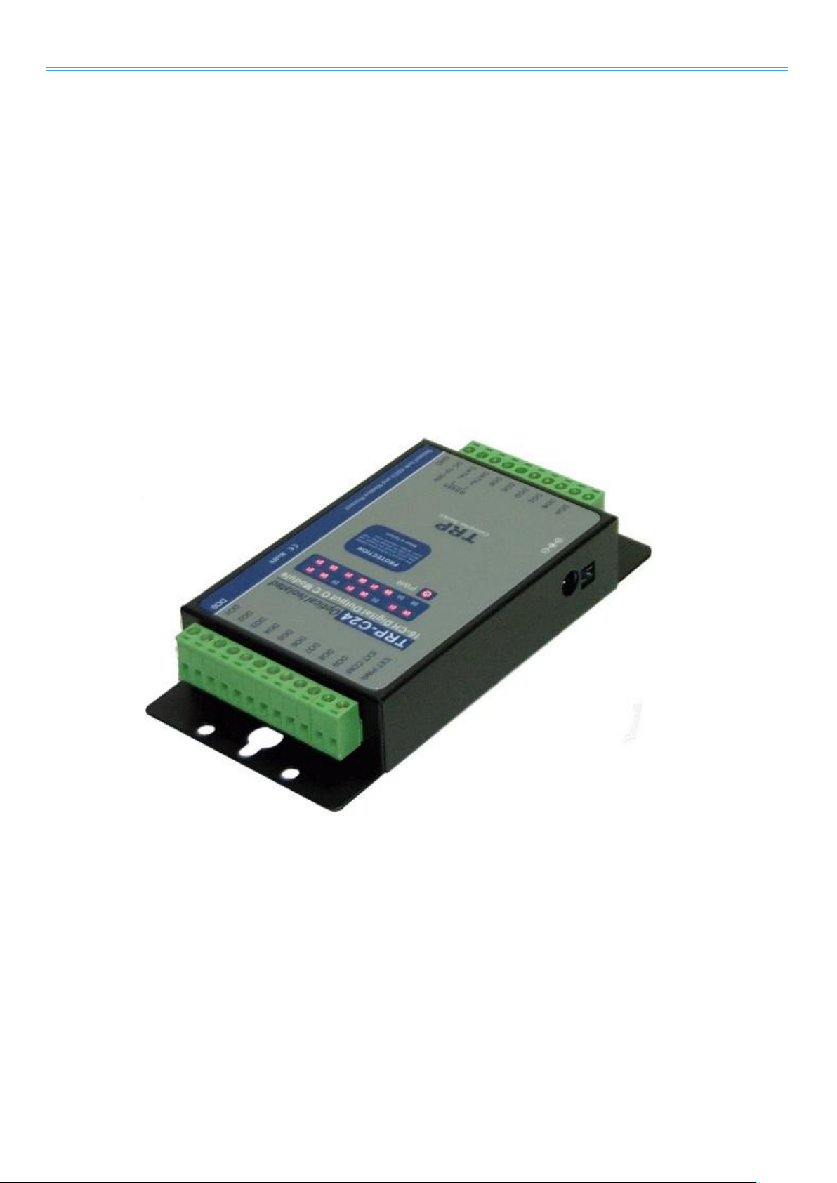
1.Introduction
C24 is an I/O box to intermediate the communication between a surveillance server and multiple peripherals.
It joins up all the major components in your surveillance network to deliver your prospective management
and protection over your property.
This manual combs the hardware/software setup for C24. Hardware-wise C24 needs a converter (C08), and
software-wise the server relies on a piece of surveillance recording software, Mainconsole, to bring all the
peripherals under control.
Easy-to-mount and flexible in communication, C24 will be the pivot in your surveillance network. Thank you
for choosing C24.
- 2 -
Page 4

The Intelligent Surveillance Solution
NUUO NVR/DVR/Hybrid NDVR System
1.1.Key Features
- Supports wide range of DC-in voltages.
- Supports ASCII and Modbus/RTU protocols
- Supports baud rates from 1.2Kbps to 115.2 Kbps.
- Digital output signal with 3750Vrms isolation protection
- Supports dual watchdog: Hardware (module) watchdog & software (host) watchdog.
- External dip-switch to deliver configuration and hardware self-test.
- Status LED for each channels
- DIN-Rail and panel mount support.
- Support screw terminal
- Includes external DC power adaptor.
- 3 -
Page 5
The Intelligent Surveillance Solution
32 bits
MS Windows XP pro SP3 / Vista SP1 / Win 7 SP1
64 bits
Win 7 SP1/ Win Server 2008 R2
S of all cam*
D C B
A
2200~1400
1400~1050
1050~550
550~
CPU
Intel Core I7
Intel Core I5
Intel Core 2
Quad Q9400
Intel Core 2
Duo
E5300
RAM
2 GB
2 GB
2 GB
1 GB
Motherboard
Intel 55 or 57 chip or above, MB
vendor Asus, Gigabyte or Intel with
Intel Chipset recommended
Intel 35 or 33 chip or above, MB
vendor Asus, Gigabyte or Intel with
Intel Chipset recommended
Display card
ATI Radeon HD 4350 or above
(ATI Driver V11-5 recommended ATI Driver V10 not support)
Ethernet
100 baseT or above, Gigabit LAN recommended
Hard Disk
250 GB or above
OS
Windows XP (32-bit) / Windows 7 (32 and 64-bit) / Windows 2008 (64-bit)
Resolution
5 M
3 M
2 M
1 M
VGA / D1
CIF
Value of
M
37
27
22
14 3 1
1.2. OS Requirement
1.3. Hardware Requirement
NUUO NVR/DVR/Hybrid NDVR System
*S=M x N
N: FPS of Camera
M: Value of IP camera resolution
- 4 -
Page 6

The Intelligent Surveillance Solution
Communication & Data Transmission
Protocol
ASCII and Modbus RTU
Interface
RS-485 differential 2 half/duplex wires
Speed
1.2Kbps to 115.2Kbps auto-switching
Data Format
Data bit 8; Parity Check: None; Stop Bit: 1
Distance
Maximum 4000 ft (1200m)
Digital Output Isolation
3750Vrms
Electrical Characteristics
Power Input Voltage
DC +10V to +30V
Maximum Output Voltage
+30V
Maximum Output Current
100mA
Power Supply
Screw terminal, or external DC adapter.
Power Consumption
1.5W
Physical Characteristics
Connection Type
Screw terminal for maximum AWG# 12~30 wire
Status LED
Status LED for power and all output channels
Dimension
151mm x 75mm x 26mm
Weight
395g
1.4. Specification
NUUO NVR/DVR/Hybrid NDVR System
- 5 -
Page 7

The Intelligent Surveillance Solution
Environment Characteristics
Operating Temperature
0 to 65 degrees C
Storage Temperature
-20 to 65 degrees C
Humidity
10~90%, non-condensing
NUUO NVR/DVR/Hybrid NDVR System
- 6 -
Page 8
The Intelligent Surveillance Solution
NUUO NVR/DVR/Hybrid NDVR System
2. Overview
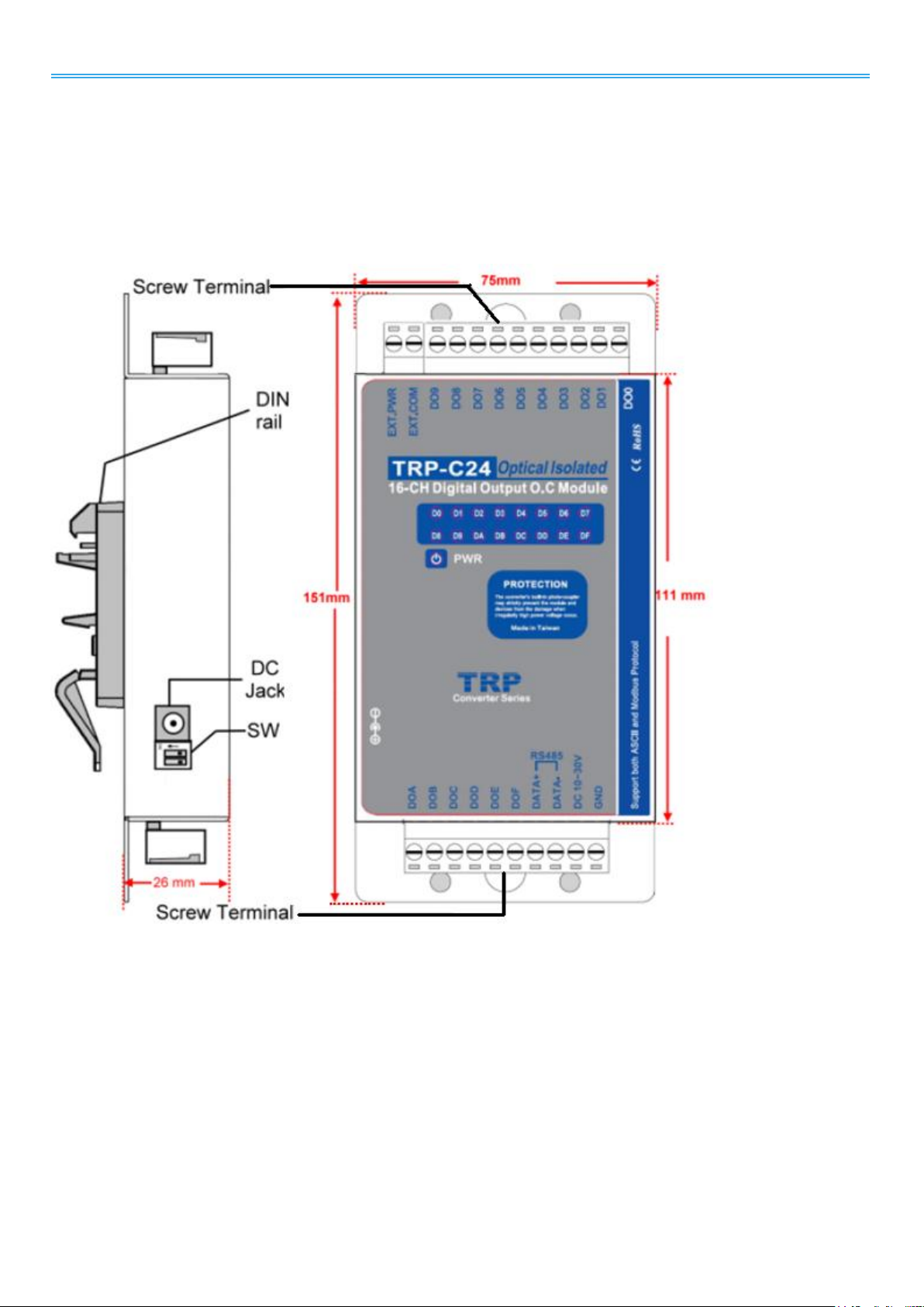
To apply C24 to your surveillance system, get to know it first. Take a look around C24. The illustration below
depicts C24 by top view and side view, with all major components and dimensions called out.
Side View Top View
Fig. 1. Overview
- 7 -
Page 9

The Intelligent Surveillance Solution
Name
Description
EXT PWR
External power for isolation. Max. 30V DC.
EXT. GND
External ground for isolation. Max. 30V DC.
DIA
Digital output Channel 10
DIB
Digital output Channel 11
DIC
Digital output Channel 12
DID
Digital output Channel 13
DIE
Digital output Channel 14
DIF
Digital output Channel 15
DATA+
RS485+
DATA-
RS485-
DC 10-30V
Input DC 10~30V
GND
DC Ground
DI0
Digital output channel 0
DI1
Digital output channel 1
DI2
Digital output channel 2
DI3
Digital output channel 3
DI4
Digital output channel 4
DI5
Digital output channel 5
DI6
Digital output channel 6
DI7
Digital output channel 7
DI8
Digital output channel 8
DI9
Digital output channel 9
2.1. Pin Definition
NUUO NVR/DVR/Hybrid NDVR System
- 8 -
Page 10
The Intelligent Surveillance Solution
NUUO NVR/DVR/Hybrid NDVR System
3. Configure Protocol & Self-test
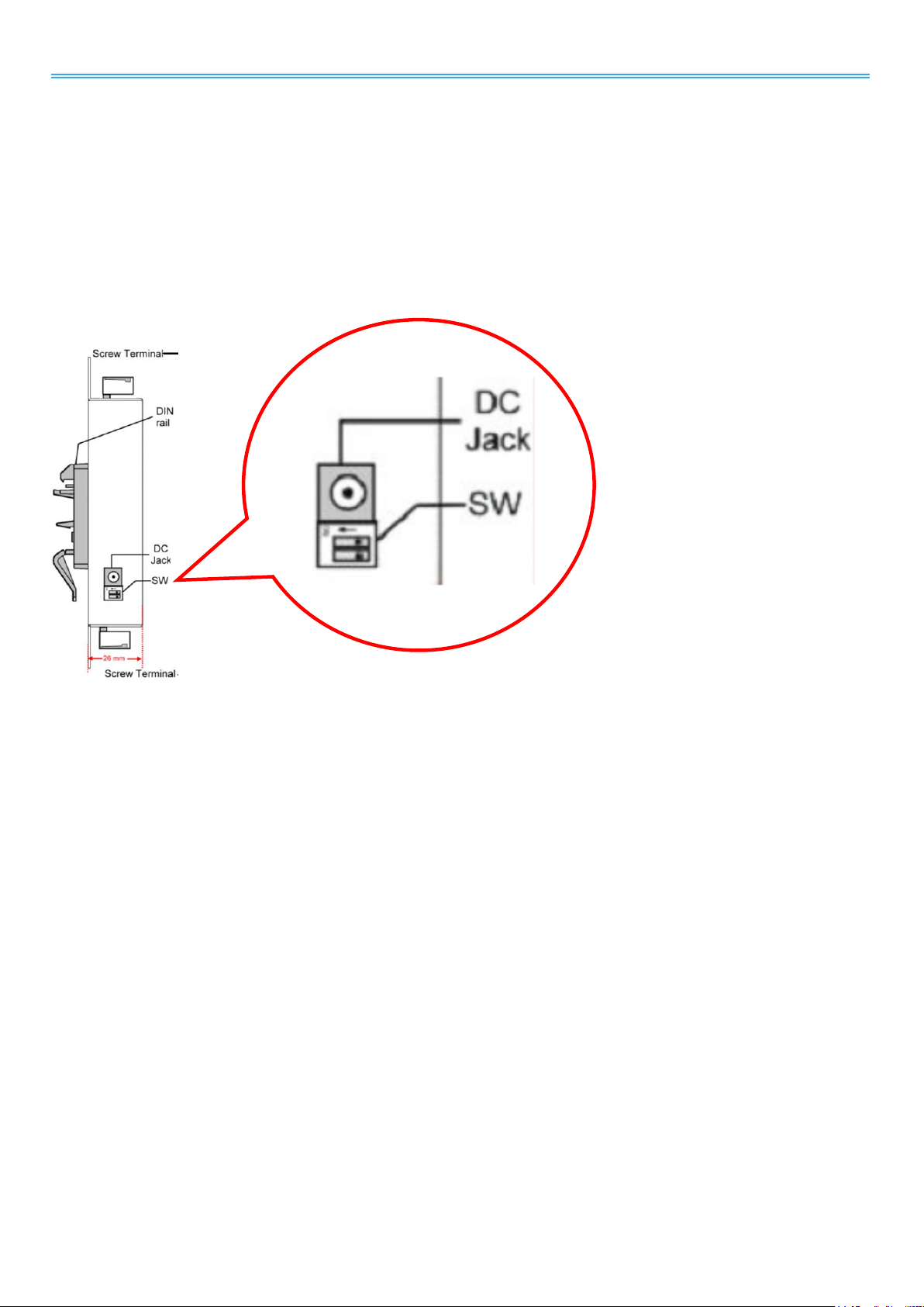
C24 supports two protocols, Modbus RTU and ASCII, to communicate with the monitoring peripherals. Which
protocol to use is adjustable by the 2-toggle dip-switch on one side of C24 as depicted in Overview.
The external dip-switch also enters C24 into self-test whereby C24 examines itself to make sure its hardware is
working properly
Fig. 2. Dip-Switch
- 9 -
Page 11

The Intelligent Surveillance Solution
Item
Description
Protocol
Modbus RTU
ID address
01
Baud rate
9600
DIO mode type
40
Checksum
Disabled
RS485 data format
Data bit 8;
Parity Check: None
Stop Bit: 1
3.1. Communication Defaults
In default state, C24 communicates by the following profile:
NUUO NVR/DVR/Hybrid NDVR System
- 10 -
Page 12

The Intelligent Surveillance Solution
Setting
Value
ID
00
BD
9600
DF
00
Name:
TRPC24
NUUO NVR/DVR/Hybrid NDVR System
3.2. Back to Initial
The dip-switch supports “Back to Initial”, a function that puts a set of communication settings back to “initial”
state in case they cannot be remembered and thus disable C24 from being communicated with.
The “initial” state represents:
To bring C24 “Back to Initial”:
Step 1: Close Mainconsole if it is opened.
Step 2: Connect C24 to power if you haven’t.
Step 3: Adjust dip-switch toggles to “off-off” position.
Step 4: Disconnect C24 from power.
Step 5: Adjust the toggles to “on-off” position.
Step 6: Reconnect C24 to power.
Step 7: Adjust the toggles to “off-on” position and C24 goes back to initial.
- 11 -
Page 13

The Intelligent Surveillance Solution
NUUO NVR/DVR/Hybrid NDVR System
4. Network Deployment Diagram
This diagram shows how server, converter (C08), I/O box (C24) are deployed within the surveillance network
to work. C08 is subject to connection to maximum 256 I/O boxes (C24/C26/C28), with each I/O box
identified by an address ranging from 0~255.
Fig. 3. Network Deployment Diagram
- 12 -
Page 14

The Intelligent Surveillance Solution
NUUO NVR/DVR/Hybrid NDVR System
5. Hardware Setup
This chapter combs through the necessary setup for the major components in the surveillance network
including:
1. peripherals,
2. I/O box C24,
3. converter C08,
4. Windows-based server PC.
5.1. Connect C08 to Server PC
An average Windows-based PC isn’t capable of RS485 communication. Therefore it needs C08, a
USB-to-RS485 converter, to be able to talk to C24.
Step 1: Connect C08 to PC an USB cable.
Step 2: On PC, install C08 driver.
- C08 driver is downloadable at www.nuuo.com > Download
Once driver is successfully installed, PC auto-detects C08 and generates a COM port for C08. Check it
up by clicking Start > Settings > Control Panel > System > Hardware tabbed page > Device Manager.
Click the plus (+) of Ports (COM & LPT). The COM port(s) in use will show.
- 13 -
Page 15

The Intelligent Surveillance Solution
Fig. 4. Connect Peripherals to C24 &
Power Supply
NUUO NVR/DVR/Hybrid NDVR System
5.2. Connect C24 to C08
After C08 and server are connected and a COM port is up between them, proceed to connect C24 to
C08.
Connect C08 (TX+, DATA+) to C24 (DATA+). Connect C08 (TX-, DATA-) to C24 (DATA-).
5.3. Connect C24 to Power Supply
Connect C24 to power supply by the power adopter that comes with your purchase.
5.4. Connect Peripherals to C24 & Power Supply
Step 1: Split a power supply to negative pole and positive pole.
Step 2: Connect the positive pole to C24’s EXT.PWR port.
Step 3: Connect the negative pole to C24’s EXT.COM port.
Step 4: Connect the negative pole of each peripheral to C24’s DO (digital output) ports.
Step 5: Bridge the positive poles of the peripheral devices to C24’s EXT.PWR port.
By the example of Fig. 4, each digital input and output device requires at least 4.0V.
- Input logical level 0: +1V (max).
- Input logical level 1: +4.0V ~ +30V.
5.5. Check C24 COM port, Baud Rate & Address
Step 1: Run Oconfig.exe on PC.
Step 2: IOconfig.exe is downloadable at www.nuuo.com > download
Step 3: Note to close Mainconsole before running IOconfig.exe
- 14 -
Page 16

The Intelligent Surveillance Solution
NUUO NVR/DVR/Hybrid NDVR System
Step 4: IOConfig opens.
Step 5: On the left pane of IOConfig, click Scan button.
Step 6: IOConfig proceeds to check the COM port, baud rate and address for the connected C24.
Step 7: In a few seconds the checking is through. Scan result shows on the right pane.
5.6. Configure Mainconsole
Step 1: Open Mainconsole on PC.
Step 2: From Mainconsole tool bar, click button.
Step 3: A menu opens.
Step 4: Click Setting > System Setting.
Step 5: Setting page opens featuring a series of tabs.
Step 6: Click I/O Device tab.
I/O Device tabbed page opens.
Step 7: In Module field, dub C24 with a name.
Step 8: By Device, specify C24 model name.
Step 9: By COM Port, select the COM port of C24 as you have noted in section 5.5. Check C24 COM port,
- 15 -
Page 17

The Intelligent Surveillance Solution
Baud Rate & Address.
Step 10: By ID, select the ID address for C24.
Step 11: Run Digital Output Simulation.
If the graphic in question lights on red, the setup is successfully made.
Step 12: Click lower-right OK and quit setting.
NUUO NVR/DVR/Hybrid NDVR System
- 16 -
 Loading...