

Page 1
MODELS QTXE080 • QTXEN080 • QTXE090C • QTXE110 • QTXEN110 • QTXE1102
QTXE SERIES
ULTRA SILENT
READ AND SAVE THESE INSTRUCTIONS
Page 1
TM
FANS
WARNING
TO REDUCE THE RISK OF FIRE, ELECTRIC SHOCK, OR INJURY TO PERSONS, OBSERVE THE FOLLOWING:
1. Use this unit only in the manner intended by the manufacturer.
If you have questions, contact the manufacturer at the address
or telephone number listed in the warranty.
2. Before servicing or cleaning unit, switch power off at service
panel and lock the service disconnecting means to prevent
power from being switched on accidentally. When the service
disconnecting means cannot be locked, securely fasten a
prominent warning device, such as a tag, to the service panel.
3. Installation work and electrical wiring must be done by a
qualified person(s) in accordance with all applicable codes
and standards, including fire-rated construction codes and
standards.
4. Sufficient air is needed for proper combustion and exhausting
of gases through the flue (chimney) of fuel burning equipment to prevent backdrafting. Follow the heating equipment
manufacturer’s guideline and safety standards such as those
published by the National Fire Protection Association (NFPA),
and the American Society for Heating, Refrigeration and Air
Conditioning Engineers (ASHRAE), and the local code authorities.
5. When cutting or drilling into wall or ceiling, do not damage
electrical wiring and other hidden utilities.
6. Ducted fans must always be vented to the outdoors.
7. Acceptable for use over a tub or shower when connected to
a GFCI (Ground Fault Circuit Interrupter) - protected branch
circuit (ceiling installation only).
8. This unit must be grounded.
CLEANING & MAINTENANCE
For quiet and efficient operation, long life, and attractive appearance - lower or remove grille and vacuum interior of unit with the
dusting brush attachment.
The motor is permanently lubricated and never needs oiling. If the
motor bearings are making excessive or unusual noises, replace
the blower assembly (includes motor and impeller).
OPERATION
Use an on/off switch or speed control to operate this ventilator. See
“Connect Wiring” for details.
Broan Models 78V and 78W may cause a motor humming noise.
Use of speed controls other than the
CAUTION
1. For general ventilating use only. Do not use to exhaust hazardous or explosive materials and vapors.
2. This product is designed for installation in ceilings up to a
12/12 pitch (45 degree angle). Duct connector must point up.
DO NOT MOUNT THIS PRODUCT IN A WALL.
3. To avoid motor bearing damage and noisy and/or unbalanced
impellers, keep drywall spray, construction dust, etc. off power
unit.
4. Please read specification label on product for further information and requirements.
Installer: Leave this manual with the homeowner.
Page 2
MODELS QTXE080 • QTXEN080 • QTXE090C • QTXE110 • QTXEN110 • QTXE1102
Cooking
Equipment
Floor
COOKING AREA
Do not install above or
inside this area.
45
o
45
o
NOT FOR USE IN
A COOKING AREA.
Page 2
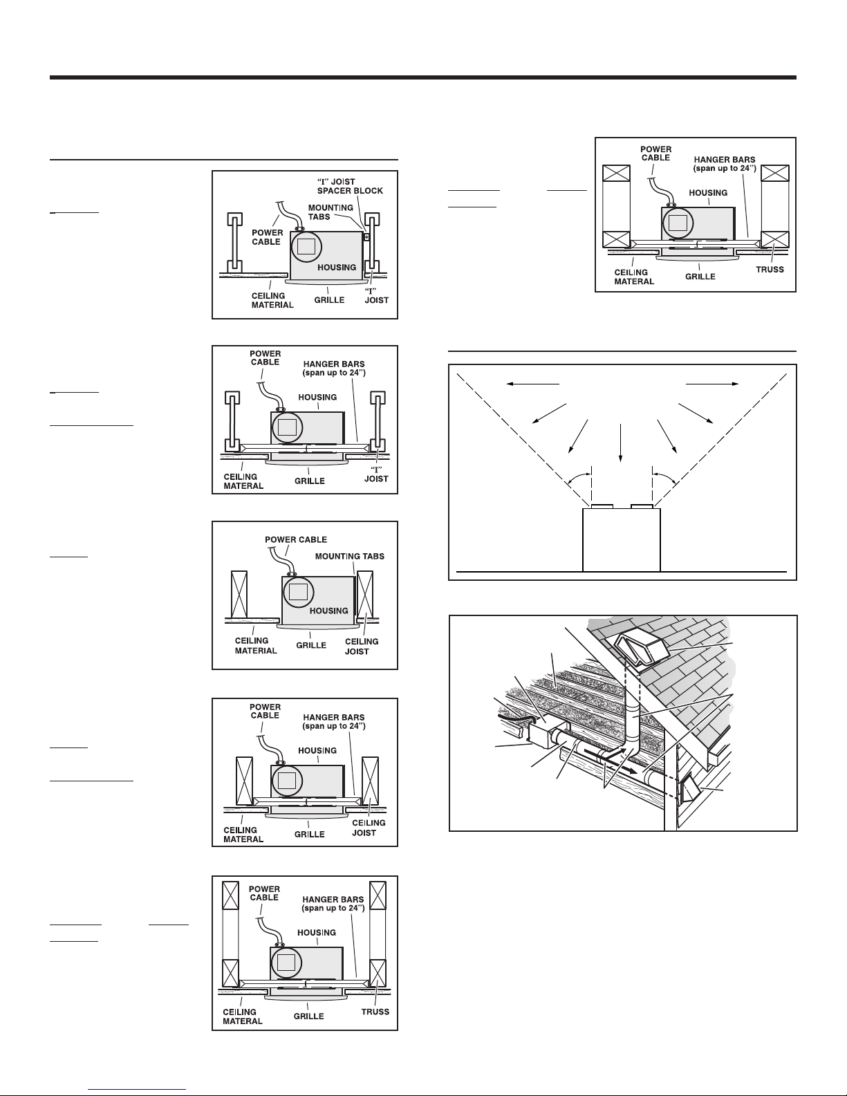
TYPICAL INSTALLATIONS
Housing mounted to
I-joists.
Housing mounted anywhere between
I-joists
using
hanger bars.
Housing mounted to
joists.
Housing mounted
anywhere between
trusses using hanger bars.
PLAN THE INSTALLATION
Housing mounted
anywhere between
joists
using
hanger bars.
Housing mounted
anywhere between
trusses using hanger bars.
Seal duct
joints with
tape.
6-IN.
ROUND
ELBOWS*
ROOF CAP*
(with built-in
damper)
Keep duct
runs short.
OR
WALL CAP*
(with built-in
damper)
HOUSING
POWER
CABLE*
Seal gaps
around
Housing.
6-IN. ROUND
*Purchase
separately.
INSULATION*
(Place around and
over Fan Housing.)
FAN
DUCT*
The ducting from this fan to the outside of the building has a strong
effect on the air flow, noise and energy use of the fan. Use the
shortest, straightest duct routing possible for best performance,
and avoid installing the fan with smaller ducts than recommended.
Insulation around the ducts can reduce energy loss and inhibit
mold growth. Fans installed with existing ducts may not achieve
their rated airflow.
Use a roof cap or wall cap that has a built-in damper to reduce
backdrafts.
Plan to supply the unit with proper line voltage and appropriate
power cable.
Page 3
MODELS QTXE080 • QTXEN080 • QTXE090C • QTXE110 • QTXEN110 • QTXE1102
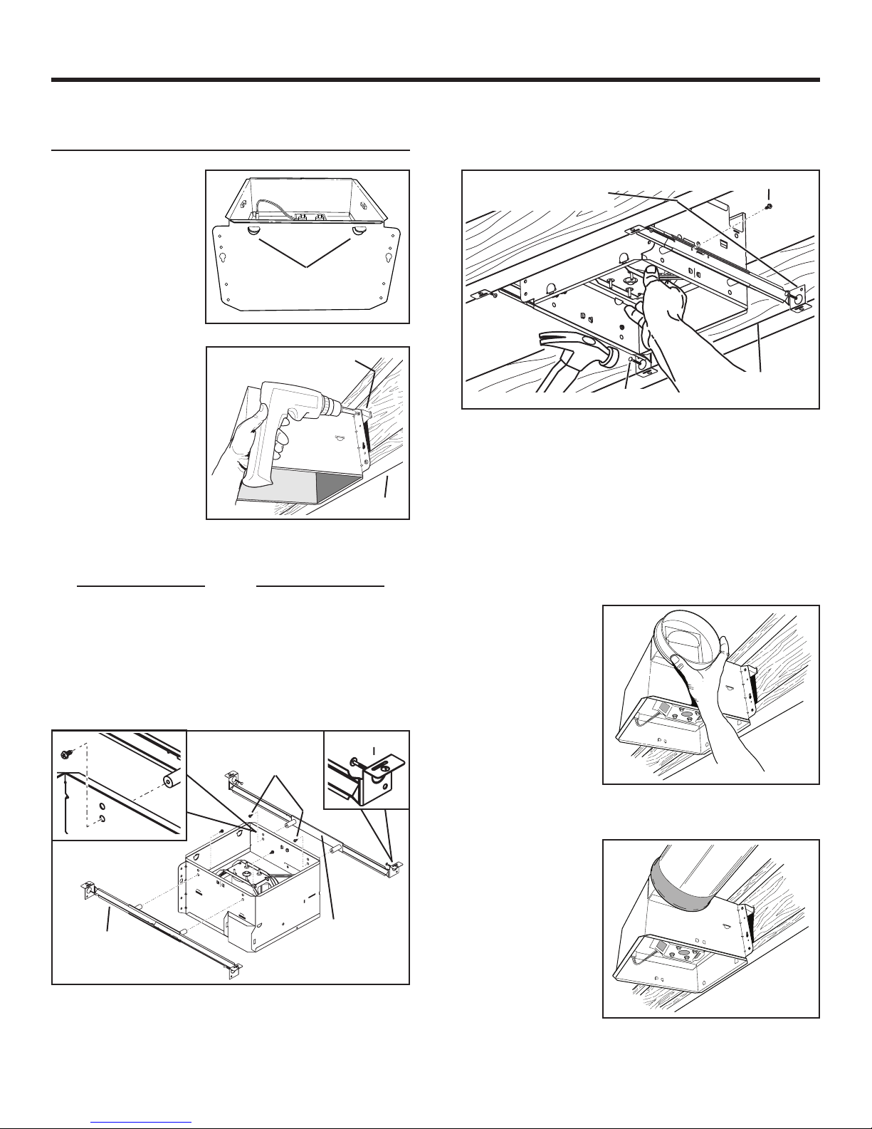
INSTALL HOUSING & DUCT
1a. Mount
housing to
joist or I-joist.
Use a pliers to bend
housing TABS out
to 900. Hold housing
in place so that
the housing tabs
contact the bottom
of the joist. The
housing mounts
with four (4) screws
or nails. Screw or
nail housing to joist
through lowest
holes in each
mounting flange,
then through
highest holes.
NOTE: Mounting to
I-JOIST (shown)
requires use
of SPACERS
(included) between
the highest hole
of each mounting
flange and the
I-joist.
(use for mounting to I-Joist)
TABS
SPACER
I-JOIST
Page 3
HOLE FOR OPTIONAL
SCREW MOUNTING (4)
NAIL (4)
Extend HANGER BARS to the width of the framing.
Hold ventilator in place with the hanger bar tabs wrapping
around the BOTTOM EDGE OF THE FRAMING.
NAIL ventilator to framing or fasten with screws (not provided)
through HOLES near nails.
* To ensure a noise-free mount: Secure hanger bars together
with SCREWS or use a pliers to crimp mounting channels
tightly around hanger bars.
SCREW (2)
*
BOTTOM EDGE
OF FRAMING
OR
1b. Mount housing anywhere between
trusses, joists, or I-joists using hanger
bars.
Sliding hanger bars are provided to allow for accurate posi-
tioning of housing anywhere between framing. They can be
used on all types of framing (I-joist, standard joist, and truss
construction) and span up to 24”.
TAB
SCREWS (4)
STD
HANGER
BAR (4)
Attach the MOUNTING CHANNELS to the housing using the
SCREWS supplied. Make sure TABS face “up” as shown. Use
the set of channel mounting holes (marked “STD”) to mount the
housing flush with the bottom of the drywall. Use the other set
of holes (not marked) to mount the housing flush with the top of
the drywall.
MOUNTING
CHANNEL (2)
2. Attach
damper/duct
connector.
Snap damper /
duct connector
onto housing.
Make sure connector is flush with
top of housing and
damper flap falls
closed.
3. Install
6-inch
round ductwork.
Connect 6-inch
round ductwork
to damper / duct
connector. Run
ductwork to a
roof cap or wall
cap. Tape all
ductwork connections to make
them secure and air tight.
Page 4
MODELS QTXE080 • QTXEN080 • QTXE090C • QTXE110 • QTXEN110 • QTXE1102
Page 4
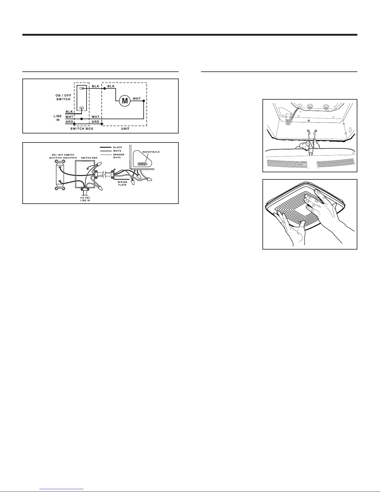
CONNECT WIRING
4. Connect electrical wiring.
Run 120 VAC house wiring to installation location. Use
proper UL approved connector to secure house wiring to
wiring plate. Connect wires as shown in wiring diagrams.
INSTALL GRILLE
5. Finish ceiling.
Install ceiling material. Cut out around housing.
6. Attach grille
to housing.
Squeeze grille
springs and insert
them into slots on
each side of housing.
7. Push grille
against
ceiling.
99045936A
Page 5

MODÈLES QTXE080 • QTXEN080 • QTXE090C • QTXE110 • QTXEN110 • QTXE1102
Page 5
VENTILATEURS ULTRA
SILENTMC (ULTRA
SILENCIEUX) SÉRIE QTXE
LISEZ CES DIRECTIVES ET CONSERVEZ-LES
AVERTISSEMENT
OBSERVEZ LES DIRECTIVES CI-DESSOUS AFIN DE RÉDUIRE
LES RISQUES D’INCENDIE, DE CHOC ÉLECTRIQUE OU DE
BLESSURES CORPORELLES :
1. N’utilisez cet appareil que de la manière prévue par le fabricant.
Si vous avez des questions, communiquez avec le fabricant à
l’adresse ou au numéro de téléphone indiqués dans la garantie.
2. Avant de procéder à l’entretien ou au nettoyage de l’appareil, coupez
l’alimentation du panneau électrique et verrouillez l’interrupteur
principal afin d’empêcher que le courant ne soit accidentellement
rétabli. S’il est impossible de verrouiller l’interrupteur principal, fixez
solidement un message d’avertissement bien visible, par exemple
une étiquette, sur le panneau électrique.
3. La pose de l’appareil et les travaux d’électricité doivent être
effectués par des personnes qualifiées conformément à la
réglementation en vigueur, notamment les normes de la
construction ayant trait à la protection contre les incendies.
4. Pour éviter les refoulements, l’apport d’air doit être suffisant pour
brûler les gaz produits par les appareils à combustion et les
évacuer dans le conduit de fumée (cheminée). Respectez les
directives du fabricant de l’appareil de chauffage et les normes de
sécurité, notamment celles publiées par la National Fire Protection
Association (NFPA), l’American Society for Heating, Refrigeration
and Air Conditioning Engineers (ASHRAE) et les codes des
autorités locales.
5. Veillez à ne pas endommager le câblage électrique ou d’autres
équipements non apparents lors de la découpe ou du perçage du
mur ou du plafond.
6. Les ventilateurs canalisés doivent toujours rejeter l’air à l’extérieur.
7. Cet appareil peut être installé au-dessus d’une enceinte de
baignoire ou de douche s’il est branché sur un circuit de dérivation
protégé par un disjoncteur différentiel de fuite à la terre (installation
au plafond seulement).
8. Cet appareil doit être relié à une mise à la terre.
NETTOYAGE ET ENTRETIEN
Pour un fonctionnement silencieux et efficace, ainsi qu’une durabilité
et une apparence supérieures, abaissez ou enlevez la grille et
nettoyez l’intérieur de l’appareil avec un aspirateur muni d’une brosse
à épousseter.
Le moteur est lubrifié en permanence et n’a pas besoin d’être huilé.
Si les roulements du moteur sont anormalement bruyants, remplacez
l’ensemble de ventilateur (incluant le moteur et la roue à ailettes).
FONCTIONNEMENT
Utilisez un interrupteur marche/arrêt ou une commande de vitesse
pour actionner le ventilateur. Pour plus de détails, consultez la section
« Câblage ». L’utilisation de commandes de vitesse autres que les
modèles Broan 78V et 78W risque de causer un grondement du moteur.
ATTENTION
1. Pour ventilation générale uniquement. N’utilisez pas cet appareil
pour évacuer des matières ou des vapeurs dangereuses ou
explosives.
2. Ce produit doit être installé dans un plafond dont la pente n’excède
pas 12/12 (45 degrés). Le raccord de conduit doit pointer vers le
haut. CE PRODUIT NE PEUT PAS ÊTRE POSÉ DANS UN MUR.
3. Pour éviter d’endommager les roulements du moteur, de
déséquilibrer les pales ou de les rendre bruyantes, débarrassez
l’appareil de la poussière de plâtre, de construction, etc.
4. Veuillez lire l’étiquette de spécifications du produit pour obtenir
plus de renseignements, notamment sur les exigences.
Installateur : Veuillez remettre ce manuel au propriétaire.
Page 6

MODÈLES QTXE080 • QTXEN080 • QTXE090C • QTXE110 • QTXEN110 • QTXE1102
CÂBLE
D'ALIMENTATION
BOÎTIER
SOLIVE
EN « I »
GRILLE
MATÉRIAU
DU PLAFOND
BARRES DE SUSPENSION
(s’allongent jusqu’à 61 cm
[24 po])
BOÎTIER
C
Â
BLE D'ALIMENTATION
ERGOTS DE MONTAGE
MATÉRIAU
DU PLAFOND
GRILLE
SOLIVE DU
PLAFOND
CÂBLE
D'ALIMENTATION
BOÎTIER
FERME
GRILLE
MATÉRIAU
DU PLAFOND
BARRES DE
SUSPENSION
(s’allongent
jusqu’à 61 cm
[24 po])
CÂBLE
D'ALIMENTATION
BOÎTIER
FERME
BARRES DE
SUSPENSION
(s’allongent jusqu’à
61 cm [24 po])
GRILLE
MATÉRIAU
DU PLAFOND
Appareil
de cuisson
Plancher
ZONE DE CUISSON
Ne pas installer au-dessus ou
à l'intérieur de cette zone.
45
o
45
o
NE PAS INSTALLER DANS
UNE ZONE DE CUISSON.
Page 6
INSTALLATIONS TYPE
Boîtier fixé à des
solives en « I ».
Boîtier monté
n’importe où entre
des solives en « I » à
l’aide des barres de
suspension.
Boîtier fixé aux
solives.
CÂBLE
D'ALIMENTATION
MATÉRIAU
DU PLAFOND
ERGOTS DE
MONTAGE
BLOC ESPACEUR
DE SOLIVE EN « I »
BOÎTIER
GRILLE
SOLIVE
EN « I »
Boîtier monté
n’importe où entre
des fermes de toit à
l’aide des barres de
suspension.
PLANIFICATION DE
L’INSTALLATION
Boîtier monté
n’importe où entre
CÂBLE
D'ALIMENTATION
des solives à l’aide
des barres de
suspension.
MATÉRIAU
DU PLAFOND
Boîtier monté
n’importe où entre
des fermes de toit à
l’aide des barres de
suspension.
BARRES DE SUSPENSION
(s’allongent jusqu’à 61 cm
[24 po])
BOÎTIER
SOLIVE DU
GRILLE
PLAFOND
ISOLANT*
(le placer autour et par-dessus
le boîtier de ventilateur.)
BOÎTIER DE
VENTILATEUR
CÂBLE
D'ALIMENTATION*
Scellez
l'écart autour
du boîtier.
15,2 CM (6 PO)
CONDUIT ROND*
*Vendu
séparément.
Scellez les
joints avec
du ruban
à conduit.
15,2 CM (6 PO)
COUDES RONDS*
CAPUCHON
DE TOIT
(avec clapet
intégré)
Utilisez des
conduits les plus
courts possible.
OU
CAPUCHON
MURAL
(avec clapet intégré)
Les conduits allant de ce ventilateur jusqu’à l’extérieur de l’habitation
ont une grande influence sur le débit d’air, le bruit du ventilateur et
sa consommation d’énergie. Pour obtenir le meilleur rendement, utilisez les conduits les plus courts et les plus droits possible et évitez
d’utiliser des conduits plus petits que ceux recommandés. L’isolation
des conduits peut contribuer à réduire les pertes d’énergie et éviter la
prolifération de moisissures. Les ventilateurs installés sur d’anciens
conduits pourraient ne pas produire leur débit d’air nominal.
Utilisez un capuchon de toit ou un capuchon mural muni d’un clapet
intégré afin de réduire les refoulements d’air.
Prévoyez l’alimentation de l’appareil avec la tension adéquate et le
câble approprié.
Page 7

MODÈLES QTXE080 • QTXEN080 • QTXE090C • QTXE110 • QTXEN110 • QTXE1102
INSTALLATION DU BOÎTIER
Page 7
ET DES CONDUITS
1a. Fixez le boîtier
aux solives ou
solives en I.
Utilisez des pinces
pour plier les ERGOTS
vers l’extérieur à 90°.
Maintenez le boîtier en
place de sorte que les
ergots touchent au bas
de la solive. Le boîtier
se fixe avec quatre (4)
vis ou clous. Vissez ou
clouez-le à la solive au
travers des trous les
plus bas de chaque
bride de montage,
puis au travers des
trous les plus hauts.
REMARQUE : La
fixation aux SOLIVES
EN « I » (illustrée)
exigel’utilisation de
CALES (incluses)
entrele trou le plus
hautde chaque bride
de montage et la
soliveen « I ».
(pour fixation aux solives en I)
OU
1b. Fixez le boîtier n’importe où entre les
fermes, solives ou solives en « I » avec
les barres de suspension.
Les barres de suspension fournies permettent de positionner
avec précision le boîtier n’importe où entre les éléments de
charpente. Elles s’utilisent pour tous les types de charpente
(solives en « I », solives ordinaires et fermes de toit) et s’allongent
jusqu’à 61 cm (24 po).
ERGOTS
CALE
SOLIVES EN « I »
ERGOT
VIS (4)
TROU POUR VISSAGE
FACULTATIF (4)
BORD INFÉRIEUR
CLOU (4)
Allongez les BARRES DE SUSPENSION à la même largeur que
la charpente.
Maintenez le ventilateur en place avec les ergots des barres de
suspension épousant le BORD INFÉRIEUR DE LA CHARPENTE.
CLOUEZ le ventilateur à la charpente ou fixez-le avec des vis (non
fournies) au travers des TROUS à côté des clous.
* Pour assurer un montage silencieux : Fixez les barres de
suspension ensemble avec des VIS ou, à l’aide de pinces, écrasez
fermement les profilés autour des barres de suspension.
DE LA CHARPENTE
VIS (2)
*
2. Fixez le
clapet /
raccord de
conduit.
Enclenchez le
clapet / raccord
de conduit sur le
boîtier. Assurezvous que le raccord
est à égalité avec
le haut du boîtier
et que le clapet
retombe fermé.
STD
BARRE DE
SUSPENSION (4)
Fixez les PROFILÉS DE MONTAGE au boîtier à l’aide des VIS
fournies. Assurez-vous que les ERGOTS sont vers le haut,
tel qu’illustré. Utilisez les trous de montage des profilés (marqués
« STD ») pour fixer le boîtier au même niveau que le dessous du
gypse. Utilisez les autres trous (non marqués) pour fixer le boîtier au
même niveau que le dessus du gypse.
PROFILÉS DE
MONTAGE (2)
3. Installez
un conduit
rond de
15,2 cm
(6po).
Raccordez le
conduit rond de
15,2 cm (6 po) au
clapet / raccord
de conduit.
Acheminez le
conduit jusqu’au
capuchon mural
ou de toit. Étanchez tous les
joints avec du ruban adhésif.
Page 8

MODÈLES QTXE080 • QTXEN080 • QTXE090C • QTXE110 • QTXEN110 • QTXE1102
INTERRUPTEUR MARCHE/ARRÊT
(vendu séparément)
BOÎTE D'INTERRUPTEUR
ENTRÉE
120 VCA
NOIR
BLANC
FIL DE TERRE
(nu)
PRISE
PLAQUE DE
CÂBLAGE
INTERRUPTEUR
MARCHE/ARRÊT
ENTRÉE
NOIR
NOIR
NOIR
BLANC
BLANC
BLANC
FIL DE TERRE
FIL DE TERRE
BOÎTE
D'INTERRUPTEUR
APPAREIL
Page 8
CÂBLAGE
4. Branchement du câblage électrique.
Acheminez un fil de 120 VCA jusqu’au lieu d’installation.
Fixezle fil à la plaque de câblage avec le connecteur
approprié homologué UL. Connectez les fils, tel qu’illustré
dans les schémas de câblage.
INSTALLER LA GRILLE
5. Finissez la surface du plafond.
Installez le matériau du plafond. Coupez-le autour du boîtier.
6. Fixez la grille
au boîtier.
Pincez les ressorts
de la grille et
insérez-les dans les
fentes de chaque
côté du boîtier.
7. Poussez la
grille contre
le plafond.
99045936A
Page 9

MODELOS QTXE080 • QTXEN080 • QTXE090C • QTXE110 • QTXEN110 • QTXE1102
VENTILADORES
ULTRA SILENCIOSOS
SERIE QTXE
LEA Y CONSERVE ESTAS INSTRUCCIONES
Página 9
ADVERTENCIA
PARA REDUCIR EL RIESGO DE INCENDIOS, DESCARGAS
ELÉCTRICAS O LESIONES PERSONALES, OBSERVE LAS
SIGUIENTES PRECAUCIONES:
1. Use la unidad sólo de la manera indicada por el fabricante. Si
tiene preguntas, comuníquese con el fabricante a la dirección
o al número telefónico que se incluyen en la garantía.
2. Antes de dar servicio a la unidad o de limpiarla, interrumpa el
suministro eléctrico en el panel de servicio y bloquee los medios de desconexión del servicio para evitar que la electricidad
se reanude accidentalmente. Cuando no sea posible bloquear
los medios de desconexión del servicio, fije firmemente un
dispositivo de advertencia (por ejemplo, una etiqueta) en un
lugar prominente del panel de servicio.
3. El trabajo de instalación y el cableado eléctrico deben ser realizados por una o más personas calificadas, y deben cumplir
con todos los códigos y normas correspondientes, incluidos los
códigos y normas de construcción específicos de protección
contra incendios.
4. Se necesita suficiente aire para que se lleve a cabo la combustión y descarga adecuadas de los gases a través del tubo
de humos (chimenea) del equipo quemador de combustible,
con el fin de evitar los contratiros. Siga las directrices y normas
de seguridad del fabricante del equipo de calentamiento, tales
como las publicadas por la Asociación Nacional de Protección
contra Incendios (National Fire Protection Association, NFPA),
la Sociedad Americana de Ingenieros de Calefacción, Refrigeración y Aire Acondicionado (American Society for Heating,
Refrigeration and Air Conditioning Engineers, ASHRAE) y las
autoridades de los códigos locales.
5. Al cortar o perforar a través de la pared o del cielo raso, no
dañe el cableado eléctrico ni otros servicios ocultos.
6. Los ventiladores con conductos deben siempre conectarse
hacia el exterior.
7. Es aceptable utilizar este producto sobre una regadera o tina
si se conecta a un circuito secundario protegido por un GFCI
(interruptor accionado por pérdida de conexión a tierra) (instalación del techo solamente).
8. Esta unidad debe conectarse a tierra.
LIMPIEZA Y MANTENIMIENTO
Para lograr un funcionamiento silencioso y eficiente, como también larga vida y una apariencia atractiva, baje o retire la rejilla
y aspire el interior de la unidad con el accesorio del cepillo para
sacudir polvo.
El motor está permanentemente lubricado y nunca necesitará
aceite. Si los cojinetes del motor están haciendo ruido excesivo
o inusual, reemplace el conjunto del ventilador (incluye el motor
y el rodete del ventilador).
OPERACIÓN
Opere este ventilador mediante un interruptor de encendido/
apagado o control de velocidad de estado sólido. Vea los detalles
en la sección “Conexión eléctrica”. El uso de los controles de la
velocidad con excepción de los modelos 78V y 78W de Broan
puede causar un ruido del tarareo del motor.
PRECAUCIÓN
1. Sólo para usarlo en ventilación general. No lo use para descargar materiales ni vapores peligrosos o explosivos.
2. Este producto se diseña para la instalación en techos hasta
una echada de 12/12 (ángulo de 45 grados). NO MONTE ESTE
PRODUCTO EN UNA TECHO.
3. Para evitar daños a los cojinetes del motor y rotores ruidosos
y/o no equilibrados, mantenga la unidad de accionamiento al
resguardo de rocío de yeso, polvo de la construcción, etc.
4. Lea la etiqueta de especificaciones del producto para ver
información y requisitos adicionales.
A la persona que realiza la instalación: Deje este manual con el dueño de la casa.
Page 10

MODELOS QTXE080 • QTXEN080 • QTXE090C • QTXE110 • QTXEN110 • QTXE1102
Equipo
para cocinar
Piso
ÁREA QUE COCINA
No instale sobre o dentro
de esta área.
45
o
45
o
NO PARA EL
USO EN UN
ÁREA QUE COCINA.
INSTALACIONES TÍPICAS
Página 10
Montaje de la cubierta en viguetas “I”.
Montaje de la cubierta en cualquier parte
entre las viguetas “I”
por medio de barras
de suspensión.
Montaje de cubierta
en viguetas.
Montaje de la cubierta en cualquier
parte entre armaduras por medio de
barras de suspensión.
PLANIFICACIÓN DE LA
INSTALACIÓN
Montaje de la cubierta en cualquier parte
entre las viguetas
por medio de barras
de suspensión.
Montaje de la cubierta en cualquier
parte entre armaduras por medio de
barras de suspensión.
CAPUCHÓN
PARA TEJADO*
(con regulador
de tiro
incorporado)
Asegurarse
de que los
conductos
sean cortos.
CAPUCHÓN
DE PARED*
(con regulador
de tiro incorporado)
del conducto
con cinta.
AISLACIÓN*
(Colocar alrededor y sobre
el compartimiento para el ventilador).
VENTILADOR
COMPARTIMIENTO
CABLE DE
ALIMENTACIÓN*
Sellar las
cavidades
alrededor del
compartimiento.
CONDUCTO CIRCULAR
DE 6 PULG.*
Sellar las uniones
*Comprar por separado.
O
CODOS
CIRCULARES
DE 6 PULG.*
Los conductos desde este ventilador hacia el exterior del edificio
tienen un gran efecto sobre el flujo de aire, el ruido y el uso de energía
del ventilador. Utilice el tramo de conductos más corto y recto posible
para obtener un desempeño óptimo y evite instalar el ventilador con
conductos menores que los recomendados. El aislamiento alrededor
de los conductos puede reducir la pérdida de energía e inhibir el desarrollo de moho. Los ventiladores instalados en conductos existentes
podrían no obtener el flujo de aire nominal.
Instale una tapa de techo o de pared que tenga un regulador de tiro
incorporado a fin de reducir los contratiros.
Alimente la unidad con el voltaje de línea y el cable eléctrico apropiados.
Page 11

MODELOS QTXE080 • QTXEN080 • QTXE090C • QTXE110 • QTXEN110 • QTXE1102
INSTALE LA CUBIERTA Y EL
CONDUCTO
1a. Instale la
cubierta en
las viguetas o
viguetas “I”.
Con un alicate, doble
las LENGÜETAS
de la cubierta a 90°.
Sostenga la cubierta
en su lugar de manera
que las lengüetas
de la cubierta hagan
contacto con la parte
inferior de la vigueta.
Para el montaje de
la cubierta se utilizan
cuatro (4) tornillos
o clavos. Atornille o
clave la cubierta a
la vigueta a través
de los orificios
más bajos de cada
brida de montaje, y
seguidamente a través
de los más altos.
NOTA: Para el montaje
en la VIGUETA “I”, tal como se ilustra, se requiere utilizar
SEPARADORES (incluidos) entre el orificio más alto de cada
brida de montaje y la vigueta “I”.
SEPARADOR (se usa para
el montaje a la vigueta “I”)
O BIEN
1b. Instale la cubierta en cualquier parte
entre las armaduras, viguetas o viguetas
“I” por medio de barras de suspensión.
Se proporcionan barras de suspensión deslizantes para facilitar
la colocación adecuada de la cubierta en cualquier parte entre la
estructura. Estas barras se adaptan a toda clase de estructuras
(construcciones de viguetas “I”, viguetas estándar y armaduras)
y se extienden a un máximo de 61 cm (24 pulg.).
TORNILLOS (4)
STD
LENGÜETA
VIGUETA “I”
LENGÜETA
Página 11
ORIFICIO PARA MONTAJE
CON TORNILLO OPCIONAL (4)
CLAVO (4)
Abra las BARRAS DE SUSPENSIÓN hasta el ancho de la
estructura.
Sostenga el ventilador en su sitio envolviendo las lengüetas de
la barra de suspensión alrededor del BORDE INFERIOR DE LA
ESTRUCTURA.
CLAVE el ventilador a la estructura o sujételo con tornillos (no
incluidos) a través de los ORIFICIOS que están cerca de los clavos.
Para lograr un montaje silencioso: acople y fije las barras de
*
suspensión con TORNILLOS, o doble los canales de montaje con
un alicate bien justos alrededor de las barras de suspensión.
TORNILLO (2)
*
BORDE INFERIOR DE
LA ESTRUCTURA
2. Acople el
conector del
regulador
de tiro/
conducto.
Conecte a presión
el conector del
regulador de tiro/
conducto en la
cubierta. Asegúrese
de que el conector
esté al ras con la
parte superior de la
cubierta y que la aleta del regulador caiga cerrada.
BARRA DE SUS-
PENSIÓN (4)
Fije los CANALES DE MONTAJE a la cubierta con los TORNILLOS
incluidos. Asegúrese de que las LENGÜETAS estén de cara hacia
arriba, tal como se muestra. Utilice el juego de orificios de montaje
del canal (marcados como “STD”) para montar la cubierta al ras
con la parte inferior de la tablarroca. Utilice el otro juego de orificios
(sin marca) para montar la cubierta al ras con la parte superior de
la tablarroca.
CANAL DE
MONTAJE (2)
3. Instale el
conducto
redondo de
6 pulgadas.
Conecte el con-
ducto redondo
de 6 pulgadas
al conector del
regulador/conducto. Extienda
el conducto hacia
una tapa de techo
o tapa de pared.
Encinte todas las conexiones de los conductos para fijarlas y
hacerlas herméticas al aire.
Page 12

MODELOS QTXE080 • QTXEN080 • QTXE090C • QTXE110 • QTXEN110 • QTXE1102
Página 12
CONEXIÓN ELÉCTRICA
4. Conecte los cables eléctricos.
Extienda el cableado de la casa de 120 V CA al lugar de la
instalación. Utilice una conexión aprobada por UL para afianzar el
cableado de la casa a la placa de cableado. Conecte los cables
tal como se ilustra en los diagramas de cableado.
INSTALE LA REJILLA
5. Termine el cielo raso.
Instale el material del cielo raso. Recorte alrededor de la cubierta.
6. Acople la
rejilla a la
cubierta.
Apriete los resortes de
la rejilla e insértelos
en las ranuras que se
encuentran a cada lado
de la cubierta.
7. Empuje la
rejilla contra
el cielo raso.
99045936A
 Loading...