

Page 1
INSTALLATION INSTRUCTIONS
READ & SAVE THESE INSTRUCTIONS!
FOR BEST RESULTS
In a new construction site, install the housing during rough-in
construction of the building. The blower assembly, light, and grille
should be installed when the finished ceiling is in place.
Installation in an existing, finished building requires an accessible
area (attic or crawl space) above the planned location. See
“INSTALLATION IN EXISTING CONSTRUCTION.”
INSTALLATION IN A NEW CONSTRUCTION SITE
Preparation of Housing Assembly
CAUTION: When handling the power unit, do not reach in the end
openings and bend the blower wheels.
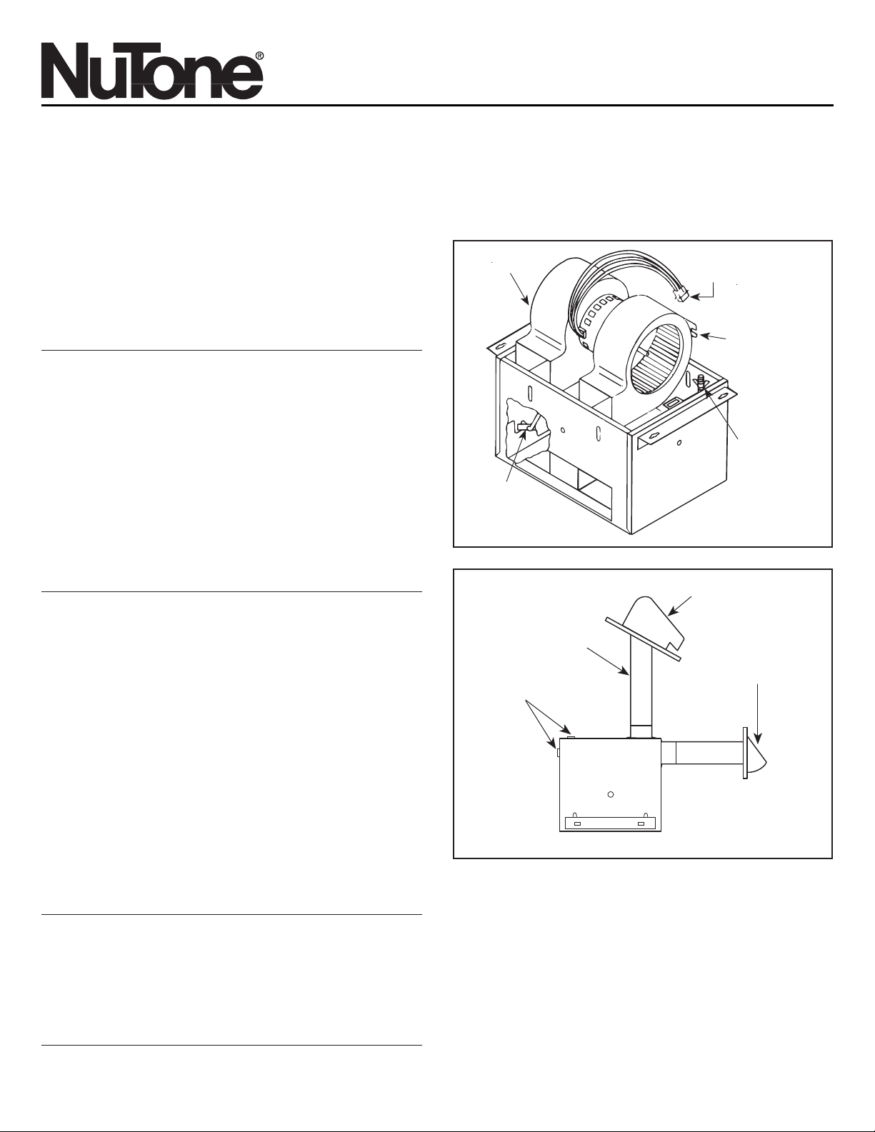
1. Refer to Figure 1. Remove power unit from housing assembly.
A. If necessary, unplug power plug from mating connector.
B. Loosen wing nuts on hanger rods that hold the power unit.
C. Unfasten hanger rods from slots and remove power unit.
D. Set power unit aside until needed.
2. Remove one of the wiring knockouts from the housing.
3. Refer to Figure 2. This unit can be ducted for either vertical or
horizontal discharge. Determine the method of discharge that will
be used.
4. Refer to Figure 3. Mount 3
1
⁄4" x 10" damper section on top of
housing for vertical discharge, or on the side of housing for
horizontal discharge with two (2) screws (furnished).
FIGURE 1
POWER
UNIT
QuieTTest®Combination Fan/Light
(with Night Light)
MODEL: QT140L
SUITABLE FOR USE OVER TUB OR SHOWER ENCLOSURE
WHEN INSTALLED IN A GFCI PROTECTED BRANCH CIRCUIT.
• Suitable for use with solid-state speed controls.
• Not for use in kitchens.
• Uses standard 3
1
⁄4" x 10" ducting.
• Designed for ceiling installation.
IMPORTANT SAFETY INSTRUCTIONS
WARNING: TO REDUCE THE RISK OF FIRE. ELECTRIC
SHOCK, OR INJURY TO PERSONS, OBSERVE THE
FOLLOWING:
A. Use this unit only in the manner intended by the manufacturer. If
you have questions, contact the manufacturer.
B. Before servicing or cleaning unit, switch power off at service
panel and lock service panel to prevent power from being
switched on accidentally.
When the service disconnecting means cannot be locked, securely
fasten a prominent warning device, such as a tag, to the service
panel.
CAUTION:
For general ventilating use only. Do not use to exhaust hazardous
or explosive materials and vapors.
INSTALLATION INSTRUCTIONS
WARNING: TO REDUCE THE RISK OF FIRE, ELECTRIC
SHOCK, OR INJURY TO PERSONS, OBSERVE THE
FOLLOWING:
A. Installation work and electrical wiring must be done by qualified
person(s) in accordance with all applicable codes and standards,
including fire-rated construction.
B. Sufficient air is needed for proper combustion and exhausting of
gases through the flue (chimney) of fuel burning equipment to
prevent back draft. Follow the heating equipment manufacturer’s
guideline and safety standards such as those published by the
National Fire Protection Association (NFPA), and the American
Society for Heating, Refrigeration, and Air Conditioning Engineers
(ASHRAE), and the local code authorities.
C. When cutting or drilling into wall or ceiling, do not damage
electrical wiring and other hidden utilities.
D. Ducted fans must always be vented to the outdoors.
E. If this unit is to be installed over a tub or shower, it must be
marked as appropriate for the application.
F. NEVER place a switch where it can be reached from a tub or
shower.
POWER
CONNECTOR
SLOT
WING NUT,
HANGER
ROD
HANGER
ROD
FIGURE 2
VERTICAL
DISCHARGE
ROOF CAP
WALL CAP
FAN HOUSING
HORIZONTAL
DISCHARGE
3
1
⁄4" X 10"
DUCT
KNOCKOUTS
Page 2
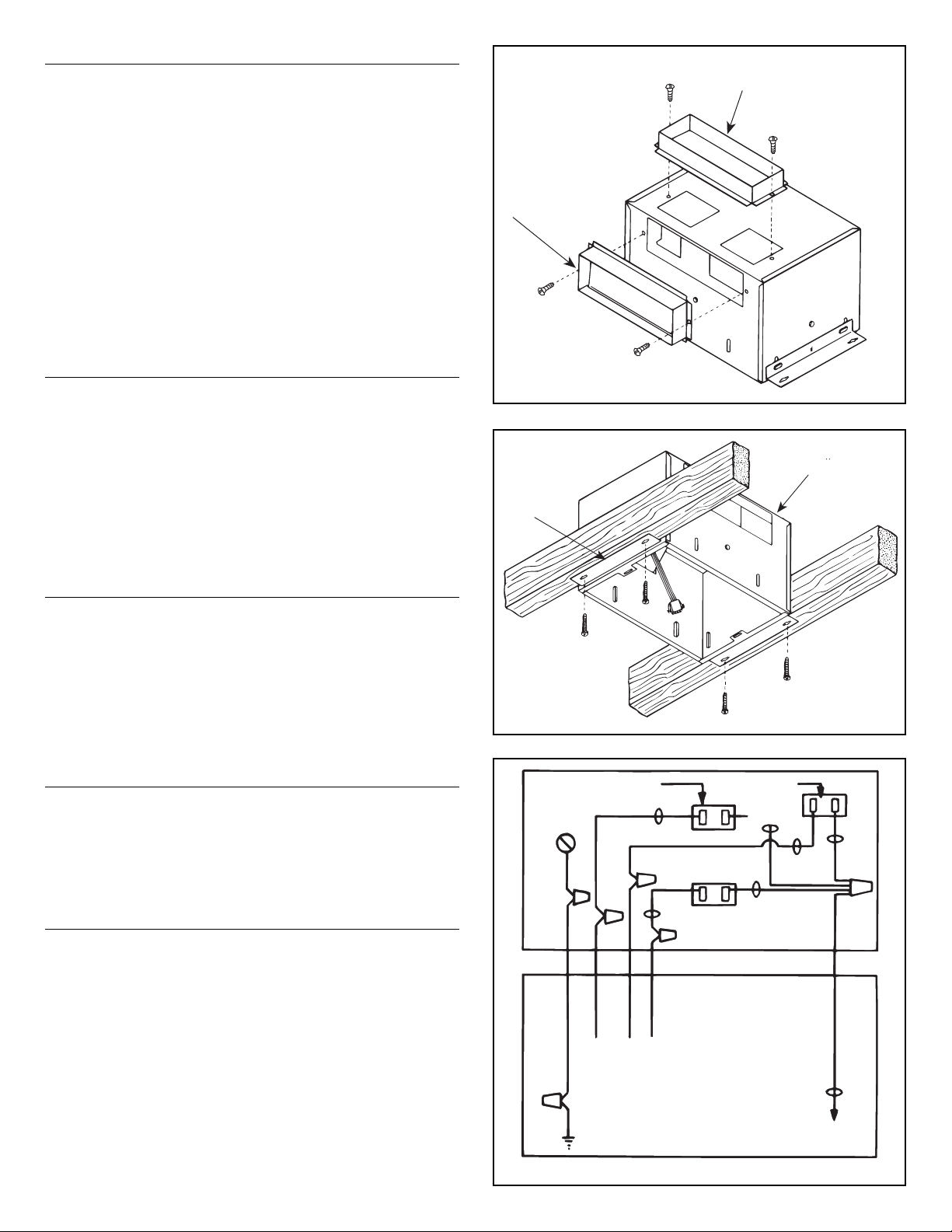
MOUNTING THE HOUSING
NOTE: This unit is designed for installation between 16" OC ceiling
joists with no framing necessary. if the building structure has 24" OC
joist construction, framing will be required.
1. Position housing between ceiling joists and adjust height to
finished ceiling. Loosen two (2) hex nuts for each mounting
bracket from inside the housing and make the adjustment. Tighten
the four (4) hex nuts.
NOTE: There are four (4) extra mounting slots in the housing long
sides for mounting or relocating the mounting brackets.
2. Refer to Figure 4. Screw housing to joists using holes in
mounting brackets and four (4) screws (furnished).
3. Refer to Figure 2 and mounting instructions included with caps.
Install standard 3
1
⁄4" x 10" ductwork from damper section to
outside wall or through roof and mount appropriate wall or roof
cap (optional).
IMPORTANT: Be sure nothing obstructs the discharge of the
unit. Make sure the insulation does not get into the ductwork or
into the blower unit.
WIRING
NOTE: All wiring connections must comply with local codes,
ordinances, and the National Electric Code and the unit must be
properly grounded.
1. Loosen screws and remove junction box.
2. Run 120vAC supply wiring with ground through switch box to
knockout in ventilator housing and secure with box connector.
3. Refer to Figure 5. Connect supply wires to the unit's wires. Black
to black; white to white. Connect ground to green ground lead.
4. Replace junction box; tighten screws.
5. Connect supply wire to a listed general use wall switch in switch
box or use a listed timer suitable for the voltage and current rating
of the fan.
POWER UNIT INSTALLATION
1. Refer to Figure 6. The Power Unit mounts with two hanger rods
to the mounting brackets. Insert the hanger rods through the holes
in the mounting bracket.
2. Position the power unit so that its discharge opening is in line with
the installed ductwork. Hold the power unit in position between the
mounting brackets and swing the hanger rods into the slots on the
power unit and securely tighten the wing nuts.
3. Plug the three-wire connector from the junction box into the three-
wire connector from the power unit, making sure plug is properly
aligned.
MOUNTING THE GRILLE ASSEMBLY
1. Place the reflector into the grille.
2. Insert light plug and night light plug into receptacles.
3. Using two provided screws, secure grille and reflector to housing.
4. Install 100 watt (maximum) light bulb into light socket.
5. Install 7 watt (maximum) C-7 candelabra type bulb into night light
socket.
6. Snap lens into place.
MAINTENANCE
• Disconnect the power before cleaning or performing any
maintenance on the unit.
• If the grille becomes soiled, use only a mild soap and water
solution for cleaning. Do not use solvents or abrasive cleaners.
VERTICAL DISCHARGE
31⁄4
" X 10" DAMPER
SECTION
FIGURE 3
31⁄4" X 10"
DAMPER
SECTION
VENTILATOR
HOUSING
FIGURE 4
MOUNTING
BRACKET
FIGURE 5
LIGHT
RECEPTACLE
BLACK
BLACK
NIGHT LIGHT
RECEPTACLE
VENT
RECEPTACLE
SWITCH
BOX
WHITE
BLACK
WHITE
WHITE
TO NIGHT-
LIGHT SWITCH
TO LIGHT SWITCH
FIELD
GROUNDING
WIRE
TO FAN SWITCH
WHITE
(COMMON)
Page 3
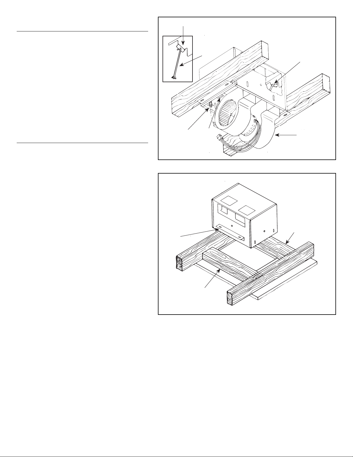
INSTALLATION IN EXISTING
CONSTRUCTION
Installing the unit in an existing house requires at least a
small accessible area (attic or crawl space) above the
planned installation location.
Review “INSTALLATION IN A NEW CONSTRUCTION
SITE” and follow all instructions which apply to your
installation.
LOCATION – Locate ventilator next to a ceiling joist.
WIRING AND DUCTING – Refer to Figure 6 for wiring
and to Figure 2 for ducting. Plan ducting and wiring
before proceeding with installation.
CAUTION: Check area above planned installation to be
sure that:
1. Ducting can be installed.
2. Wiring can be run to the planned location.
3. No wiring or other obstruction might interfere with
installation.
INSTALLATION FROM ACCESSIBLE
AREA ABOVE (Using headers)
1. From below, drill a small hole in ceiling at the planned
location. Stick clothes hanger through hole to help
locate the area from above.
2. Locate hole in attic or crawl space.
3. Refer to Figure 7. In attic or crawl space, mark ceiling
for cutout by using the housing as a template. Cutout
dimensions 10
3
⁄
16"x14
3
⁄
8". The short side (10
3
⁄
16") or
cutout must be next to the ceiling joist.
4. Make cutout along marked line.
NOTE: Refer to Figure 3. If ceiling is plaster, cutout
should be made from below to avoid chipping plaster.
5. Refer to Figure 7. Install headers between joists using
nails or screws leaving 10
3
⁄
16" between them.
6. Refer to Figure 7. The mounting brackets must be
mounted on the long sides of the housing. NOTE: Each
of the mounting brackets are secured by two (2) hex
nuts.
7. Refer to pages 1 and 2. Mount damper section to
housing, install housing and connect wiring and ducting.
Install power unit, blower assembly and grille.
HANGER
ROD
FIGURE 6
HANGER
ROD SLOT
POWER
UNIT
MOUNTING
BRACKET
HOOK HANGER
RODS FROM
INSIDE TO
OUTSIDE
HEADER
FIGURE 7
MOUNTING
BRACKET
HEADER
Page 4

Product specifications subject to change without notice.
4820 Red Bank Road, Cincinnati, Ohio 45227
Printed in U.S.A., Rev. 04/01, Part No. 35746
One Year Limited Warranty
WARRANTY OWNER: NuTone warrants to the original consumer purchaser of its products that such products will be free from defects in materials or workmanship for a period
of one (1) year from the date of original purchase. THERE ARE NO OTHER WARRANTIES, EXPRESS OR IMPLIED, INCLUDING, BUT NOT LIMITED TO, IMPLIED
WARRANTIES OF MERCHANTABILITY OR FITNESS FOR A PARTICULAR PURPOSE.
During this one year period, NuTone will, at its option, repair or replace, without charge, any product or part which is found to be defective under normal use and service.
THIS WARRANTY DOES NOT EXTEND TO FLUORESCENT LAMP STARTERS OR TUBES, FILTERS, DUCT, ROOF CAPS, WALL CAPS AND OTHER ACCESSORIES
FOR DUCTING. This warranty does not cover (a) normal maintenance and service or (b) any products or parts which have been subject to misuse, negligence, accident,
improper maintenance or repair (other than by NuTone), faulty installation or installation contrary to recommended installation instructions.
The duration of any implied warranty is limited to the one year period as specified for the express warranty. Some states do not allow limitation on how long an implied warranty
lasts, so the above limitation may not apply to you.
NUTONE’S OBLIGATION TO REPAIR OR REPLACE, AT NUTONE’S OPTION, SHALL BE THE PURCHASER’S SOLE AND EXCLUSIVE REMEDY UNDER THIS
WARRANTY. NUTONE SHALL NOT BE LIABLE FOR INCIDENTAL, CONSEQUENTIAL OR SPECIAL DAMAGES ARISING OUT OF OR IN CONNECTION WITH
PRODUCT USE OR PERFORMANCE. Some states do not allow the exclusion or limitation of incidental or consequential damages, so the above limitation or exclusion may
not apply to you. This warranty gives you specific legal rights, and you may also have other rights, which vary from state to state. This warranty supersedes all prior warranties.
WARRANTY SERVICE: To qualify for warranty service, you must (a) notify NuTone at the address stated below or telephone 1/800-543-8687, (b) give the model
number and part identification and (c) describe the nature of any defect in the product or part. At the time of requesting warranty service, you must present
evidence of the original purchase date.
Date of Installation Builder or Installer
Model No. and Product Description
IF YOU NEED ASSISTANCE OR SERVICE:
For the location of your nearest NuTone Independent Authorized Service Center:
Residents of the contiguous United States Dial Free 1-800-543-8687
Please be prepared to provide:
Product model number • Date and Proof of purchase • The nature of the difficulty
Residents of Alaska or Hawaii should write to: NuTone Inc. Attn: Department of National Field Service, 4820 Red Bank Road, Cincinnati Ohio 45227-1599.
Residents of Canada should write to: Broan-NuTone Canada, 1140 Tristar Drive, Mississauga, Ontario, Canada L5T 1H9.
Page 5

Combinación Lámpara-Ventilador QuieTTest
®
(con iluminación nocturna)
MODELO: QT140L
APROPIADO PARA SER UTILIZADO EN EL RECINTO
DE LA BANERA O DE LA DUCHA CUANDO SE INSTALA
EN UN CIRCUITO DERIVADO PROTEGIDO POR GFCI.
INSTRUCCIONES DE INSTALACION
¡
LEA Y GUARDE ESTAS INSTRUCCIONES!
FIGURA 1
UNIDAD DE
POTENCIA
•
Apropiado para usarla con controles de velocidad de estado sólido.
• No se puede utilizar en cocinas.
• Utiliza un conducto estándar de 3
1
⁄4" x 10".
• Diseñado para la instalación en techos.
INSTRUCCIONES IMPORTANTES
DE SEGURIDAD
ADVERTENCIA: PARA REDUCIR EL RIESGO DE
INCENDIO, CHOCQUE ELECTRICO O LESIONES A LAS
PERSONAS, OBSERVE LO SIGUIENTE:
A. Utilice esta unidad solamente de la manera planeada por el
fabricante. Si tiene alguna pregunta, póngase en contacto
con el fabricante.
B. Antes de reparar o limpiar la unidad, apague la corriente del
panel de servicio y cierre con llave el panel de servicio par
evitar que la corriente se encienda accidentalmente.
PRECAUCION:
Solamente para ventilación general. No lo utilice para
expulsar materiales y vapores peligrosos o explosivos.
INSTRUCCIONES DE INSTALACION
ADVERTENCIA: PARA REDUCIR EL RIESGO DE
INCENDIO, CHOQUE ELECTRICO O LESIONES A LAS
PERSONAS, OBSERVE LO SIGUIENTE:
A. El trabajo de instalación y el cableado eléctrico deben ser
realizados por una (s) persona (s) calificada (s) de acuerdo
con todos los códigos y estándares aplicables, incluyendo
la contrucción según los estándares contra incendios.
B. El flujo del aire de combustión necesario para el manejo
seguro del equipo quemador de combustible puede verse
afectado por el funcionamiento de esta unidad. Siga las
pautas y estándares de seguridad del fabricante para el
equipo de calefacción como las publicadas por la Asociación
Nacional de Portección contra Incendios (NFPA), por la
Asociación Norteamericana de Ingenieros de Calefacción,
Refrigeración y Aire Acondicionado (ASHRAE) y por las
autoridades de códigos locales.
C. Cuando corte o taladre en la pared o el techo, no dañe el
cableado eléctrico ni otros servicios escondidos.
D. Los ventiladores entubados siempre deben estar ventilados
hacia el exterior.
E. Si la unidad se va a instalar encima de una bañera o ducha,
aquélla debe estar señalada como apropiada para la aplicación.
F. No coloque NUNCA un interruptor donde pueda ser
alcanzado desde la bañera o ducha.
PARA OBTENER MEJORES RESULTADOS
En la construcción nueva, instale la caja (unidad de potencia)
durante la etapa de enterramiento de la instalación eléctrica del
edificio. El conjunto de lámpara y la rejilla deben de instalarse
después de que el techo acabado esté en su sitio.
La instalación en un edificio avabado, ya existente, requiere un
área accesible (ático o sóntano de pequeña altura que queda entre
el primer piso y el terreno natural) sobre la localización planeada.
Consulte “INSTALACION EN UNA CONSTRUCCION EXISTENTE”.
CONECTADOR
DE POTENCIA
RANURA
TUERCA DE
MARIPOSA,
VARILLA DE
SUSPENSION
VARILLA
DE
SUSPENSION
FIGURA 2
DESCARGA
VERTICAL
CAPERUZA
DE TEJADO
CAPERUZA
DE PARED
CAJA DEL
VENTILADOR
DESCARGA
HORIZONTAL
CONDUCTO
DE 3
1
⁄4" X 10"
AGUJEROS CIEGOS
INSTALACION EN UN LUGAR
DE CONTRUCCION NUEVA
Preparación del conjunto de la caja
PRECAUCION: Cuando maneje la unidad de potencia, no toque las
aberturas de los extremos ni doble las rudeas del ventilador.
1. Refiérase a la Figura 1. Quite la unidad de potencia del conjunto
de la caja.
A. Si es necisario, desenchufe la clavija de toma de corriente del
conectador de acoplamiento.
B. Afloje las tuercas de mariposa de las varillas de suspensión
que sostienen la unidad de potencia.
C. Suelte las varillas de suspensión de las ranuras y quite la
unidad de potencia
D. Ponga la unidad de potencia a un lado hasta que la necesite.
2. Quite uno de los agujeros ciegos del cableado de la caja.
3. Refiérase a la Figura 2. En esta unidad el conducto se puede
colocar para descarga vertical u horizontal. Determine el método
de descarga que se utilizará.
4. Refiérase a la Figura 3. Monte la sección del regulador de tiro de
3
1
⁄4" x 10" sobre la caja para la descarga vertical, o en el lado de
la caja para la descarga horizontal con dos (2) tornillos (incluidos).
Page 6

MONTAJE DE LA CAJA
NOTA: Esta unidad está diseñada para la instalación entre viguetas
de techo separadas 16" entre los centros sin necesidad de armazón.
Si la estructura del edificio tiene una construcción de viguetas
separadas 24" entre los centros, será necesario un armazón.
1. Coloque la caja entre las viguetas de techo y ajuste la altura al
techo acabado. Afloje dos (2) tuercas hexagonales para cada
consola para el montaje desde el interior de la caja y haga el
ajuste. Apriete las cuatro (4) tuercas hexagonales.
NOTA: Hay cuatro (4) ranuras extras de montaje en los lados
largos de la caja para montar o cambiar de sitio las consolas para
el montaje.
2. Refiérase a la Figura 4. Atornille la caja a las viguetas utilizando
los agujeros de las consolas para el montaje y cuatro (4) tornillos
(incluidos).
3. Refiérase a la Figura 2 y a las instrucciones para el montaje
incluidas con las caperuzas. Instale el conducto estándar de
3
1
⁄4" x 10" desde la sección del regulador de tiro hasta la pared
exterior o a través del tejado y monte la caperuza de pared o
tejado (opcional).
INPORTANTE: Asegúrese de que nada obstruya la descarga de
la unidad. Asegúrese de que el aislamiento no entre en el
conducto ni en la unidad del ventilador.
CABLEADO
NOTA: Todas las conexiones del cableado deben cumplir
con los códigos y las ordenanzas locales y con el reglamento
de instalaciones eléctricas nacionales y la unidad debe estar
puesta a tierra adecuadamente.
1. Afloje los tornillos y saque la caja de empalme.
2. Pase un cableado de 120v CA con conexión a tierra a través de
la caja del interruptor al agujero ciego en la caja del ventilador y
fíjelo con un conectador de caja.
3. Refiérase a la Figura 5. Conecte los cables de alimentación a los
cables de la unidad. Negro con negro; blanco con blanco. Conecte
la puesta a tierra con el conductor verde de conexión a tierra.
4. Vuelva a colocar la caja de empalme; apriete los tornillos.
5. Conecte el cable de alimentación a un interruptor de pared
certificado de uso general en la caja del interruptor o utilice un
temporizador certificado apropiado para el voltaje y el tipo de
corriente del ventilador.
INSTALACION DE LA UNIDAD DE POTENCIA
1. Refiérase a la Figura 6. La unidad de potencia se monta con dos
varillas de suspensión en la consola de montaje. Inserte las varillas
de suspensión a través de los agujeros de la consola de montaje
.
2. Coloque la unidad de potencia de manera que la abertura de
descarga esté alindeada con el conducto instalado. Sostenga la
unidad de potencia en su lugar entre las consolas de montaje y
gire las varillas de suspensión para introducirlas en las ranuras
de la unidad de potencia y apriete bien las tuercas de mariposa.
3. Enchufe el conector de tres hilos de la caja de empalme en el
conector de tres hilos de la unidad de potencia, asegurándose
de que el enchufe esté bien alineado.
MONTAJE DEL CONJUNTO DE LA REJILLA
1. Coloque el reflector en la rejilla.
2. Inserte el enchufe de la luz y el enchufe de la luz nocturna
en los receptáculos.
3. Utilizando dos tornillos incluidos, fije la rejilla y el reflector a la caja.
4. Instale una bombilla de 100 watt (máximo) en el portalámparas.
5. Instale una bombilla tipo candelabre C-7 de 7 watt (máaximo) en
el enchufe de iluminación nocturna.
6. Presione la lente hasta que quede en su sitio.
MANTENIMIENTO
• Desconecte la corriente antes de limpiar o realizar cualquier clase
de mantenimiento en la unidad.
• Si la rejilla se ensucia, use solamente una solución de jabón
suave y agua para la limpiarla. No utilice disolventes ni
limpiadores abrasivos.
SECCION DEL
REGULADOR DE TIRO
DE 31⁄4" X 10" DE LA
DESCARGA VERTICAL
FIGURA 3
SECCION DEL
REGULADOR
DE TIRO DE
31⁄4" X 10"
CAJA DEL
VENTILADOR
FIGURA 4
CONSOLA
PARA EL
MONTAJE
RECEPTACULO
DE LA LUZ
RECEPTACULO DE
LA LUZ NOCTURNA
NEGRO
RECEPTACULO DE
VENTILACION
BLANCO
BLANCO
(NEUTRO)
CAJA DEL
INTERRUPTOR
CABLE PUESTO
A TIERRA DEL
EMPLAZAMIENTO
HACIA EL INTERRUPTOR
DE LA LUZ
HACIA EL INTERRUPTOR DE
ILUMINACION NOCTURNA
HACIA EL INTERRUPTOR
DEL VENTILADOR
BLANCO
NEGRO
NEGRO
BLANCO
FIGURA 5
Page 7

INSTALACION EN UNA CONSTRUCCION
EXISTENTE
La instalación de la unidad en una casa existente requiere
al menos un área pequeña accesible (ático o sótano de
pequeña altrua que queda entre el primer piso y el terreno
natural) sobre la localización de la instalación planeada.
Repase “INSTALACION EN UN LUGAR DE
CONSTRUCCION NUEVA” y siga todas las instrucciones
que correspondan a su instalación.
UBICACION – Coloque el ventilador junto a una vigueta
de techo.
CABLEADO Y CONDUCTO – Refiérase a la Figura 6
para el cableado y a la Figura 2 para el conducto.
Planee el conducto y el cableado antes de continuar con
la instalación.
PRECAUCION: Compruebe el área sobre la instalación
planeada para asegurarse de que:
1. El conducto se puede instalar o el área es suficiente
para el montaje adecuado.
2. El cableado se puede llevar a la ubicación planeada.
3. Ningún cableado ni otra obstrucción puede interferir
con la instalación.
INSTALACION DESDE UN AREA
SUPERIOR ACCESIBLE
(Utilizando soportes)
1. Desde abajo, taladre un agujero de menos en el techo
en el lugar planeado. Meta una percha para colgar la
ropa por el agujero para ayudarle a localizar el área
desde arriba.
2. Localice el agujero en el ático o sótano de pequeña altura.
3. Refiérase a la Figura 7. En el ático o en el sótano
de pequeña altura, marque el techo para el recorte
utilizando la caja como plantilla. Recorte las dimensiones
10
3
⁄
16
"x14
3
⁄
8
". El lado corto (10
3
⁄
16
") o el recorte debe
estar junto a la vigueta de techo.
4. Haga el recorte a lo largo de la línea marcada.
NOTA: Refiérase a la Figura 3. Si el techo es de yeso,
el recorte se debe hacer desde abajo para evitar las
virutas del yeso.
5. Refiérase a la Figura 7. Instale los soportes entre las
viguetas utilizando clavos o tornillos dejando 10
3
⁄
16"
entre ellos.
6. Refiérase a la Figura 7. Las consolas para el montaje
deben montarse en los lados largos del alojamiento.
NOTA: Cada una de las consolas de montaje se fijan
con dos (2) tuercas hexagonales.
7. Refiérase a las páginas 1 y 2. Monte la sección del
regulador de tiro en la caja, instale la caja y conecte el
cableado y el conducto. Instale la unidad de potencia,
el conjunto del ventilador y la rejilla.
VARILLA
DE SUSPENSION
FIGURA 6
RANURA
UNIDAD DE
POTENCIA
CONSOLA PARA
EL MONTAJE
ENGANCHE LAS
VARILLAS DE
SUSPENSION
DESDE FUERA
HACIA
DENTRO
SOPORTE
FIGURA 7
SOPORTE
CONSOLA
PARA EL
MONTAJE
VARILLA DE
SUSPENSION
Page 8

Las especificaciones del producto están sujetas a cambio sin previo aviso.
4820 Red Bank Road, Cincinnati, Ohio 45227
Impreso en los EE.UU.
Garantía Limitada de un Año
GARANTÍA DEL PROPIETARIO: NuTone garantiza al comprador consumidor original de sus productos, por el período de un (1) año desde la fecha original de compra,
que tales productos están libres de defectos en material y mano de obra. NO HAY OTRAS GARANTÍAS, EXPRESADAS O SOBREENTENDIDAS, INCLUYENDO, PERO
NO LIMITADAS A, GARANTÍAS NO EXPRESADAS DE MERCANTIBILIDAD O ADAPTABLES A UN PROPÓSITO EN PARTICULAR.
Durante este período de un año, NuTone reparará o reemplazará a su opción y sin costo, cualquier producto o parte que se encuentre defectuoso bajo condiciones
normales de uso y servicio. ESTA GARANTÍA NO CUBRE A LOS ARRANCADORES PARA LÁMPARAS FLUORESCENTES O A LOS TUBOS FLUORESCENTES,
FILTROS, DUCTOS, TAPAS DE TECHO, TAPAS DE PARED Y OTROS ACCESORIOS PARA CANALIZACIÓN. Esta garantía no cubre (a) Mantenimiento y servicios
normales (b) Productos o partes sujetos al mal uso, negligencia, accidente, mantenimiento inadecuado o reparaciones (por otros ajenos a NuTone), instalación defectuosa
o a una instalación contraria a las instrucciones de instalación recomendadas.
La duración de cualquier garantía no expresada está limitada a un período de un año según se especifica en la garantía expresada. Algunos estados no permiten
limitación en cuanto a la duración de una garantía no expresada, por lo que la limitación arriba indicada puede que no se aplique a Ud.
LA OBLIGACIÓN DE NUTONE DE REPARAR O REEMPLAZAR A SU OPCIÓN, SERÁ EL ÚNICO Y EXCLUSIVO RECURSO QUE TENDRÁ EL COMPRADOR BAJO
ESTA GARANTÍA. NUTONE NO SERÁ RESPONSABLE POR DAÑOS INCIDENTALES, CONSECUENTES O ESPECIALES QUE RESULTEN A CONSECUENCIA O
SEAN INDEPENDIENTE DEL USO O DESEMPEÑO DEL PRODUCTO. Algunos estados no permiten la exclusión o limitación de daños incidentales o consecuentes, de
modo que la limitación o exclusión arriba indicada pueda que no se aplique a Ud. Esta garantía le proporciona derechos legales específicos, y Ud. puede tener otros
derechos, los cuales varían de estado a estado. Esta garantía reemplaza a todas las garantías anteriores.
SERVICIO DE GARANTÍA: Para tener derecho al servicio de garantía, Ud. debe (a) Notificar a NuTone a la dirección indicada más abajo o al teléfono 1/800-5438687, (b) indicar el número de modelo y la identificación de la parte y (c) describir la naturaleza de cualquier defecto en el producto o parte. Al momento de
solicitar el servicio por la garantía, Ud. debe presentar la evidencia de la fecha original de compra.
Fecha de instalación Constructor o instalado
Nº de modelo y descripción del producto
SI NECESITA ASISTENCIA O SERIVIVIO:
Para obtener la localización del Centro de Servicio Autorizado:
Los residentes de los Estados Unidos contiguos llam gratis al: 1 800 543 8687
Por favor, esté preparado para suministrar • Fecha y prueba de compra • La naturaleza de la dificultad
Los residentes de Alaska o Hawaii deben escribir a: NuTone Inc. Attn: Department of National Field Service, 4820 Red Bank Road, Cincinnati Ohio USA 45227-1599.
Los residentes de Canada: Écrivez à Broan-NuTone Canada, 1140 Tristar Drive, Mississauga, Ontario Canada L5T 1H9.
Rev. 03/2001
 Loading...