

Page 1
INSTALLATION INSTRUCTIONS
READ & SAVE THESE INSTRUCTIONS!
®
IMPORTANT SAFETY INSTRUCTIONS
WARNING: TO REDUCE THE RISK OF FIRE. ELECTRIC
SHOCK, OR INJURY TO PERSONS, OBSERVE THE
FOLLOWING:
A. Use this unit only in the manner intended by the manufacturer.
If you have questions, contact the manufacturer.
B. Before servicing or cleaning unit, switch power off at service
panel and lock service panel to prevent power from being
switched on accidentally.
When the service disconnecting means cannot be locked, securely
fasten a prominent warning device, such as a tag, to the service
panel.
CAUTION:
For general ventilating use only. Do not use to exhaust hazardous
or explosive materials and vapors.
INSTALLATION INSTRUCTIONS
WARNING: TO REDUCE THE RISK OF FIRE, ELECTRIC
SHOCK, OR INJURY TO PERSONS, OBSERVE THE
FOLLOWING:
A. Installation work and electrical wiring must be done by qualified
person(s) in accordance with all applicable codes and standards,
including fire-rated construction.
B. Sufficient air is needed for proper combustion and exhausting of
gases through the flue (chimney) of fuel burning equipment to
prevent back drafting. Follow the heating equipment
manufacturer's guideline and safety standards such as those
published by the National Fire Protection Association (NFPA),
and the American Society for Heating, Refrigeration and Air
Conditioning Engineers (ASHRAE), and the local code
authorities.
C. When cutting or drilling into wall or ceiling, do not damage
electrical wiring and other hidden utilities.
D. Ducted fans must always be vented to the outdoors.
E. If this unit is to be installed over a tub or shower, it must be
marked as appropriate for the application.
F. NEVER place a switch where it can be reached from
a tub or shower.
•
Suitable for use with solid state speed controls.
•
Uses standard 31⁄
4
" x 10" ducting.
•
Designed for ceiling installation.
•
Do not mount over bathtub or shower stall enclosure.
•
Not for use in kitchens.
•
The ventilator consists of the housing, mounting brackets, junction
box, power unit/blower assembly, damper section and grille
assembly.
FAN MUST NOT BE INSTALLED IN A CEILING THERMALLY
INSULATED TO A VALUE GREATER THAN R-40.
FOR BEST RESULTS
When installing the ventilator in a new construction site, install the
housing during the rough-in construction of the building. The power
unit and grille should be installed after the finished ceiling is in place.
To install the ventilator in an existing building, an accessible area
(attic or crawl space) is required from above the planned location.
QuieTTest
®
Twin Blower Ventilator
MODELS: QT130, QT200 & QT300
For Ceiling Installation
INSTALLATION IN
A NEW CONSTRUCTION SITE
PREPARATION
CAUTION: When handling the power unit do not reach in the end
openings and bend the blower wheels.
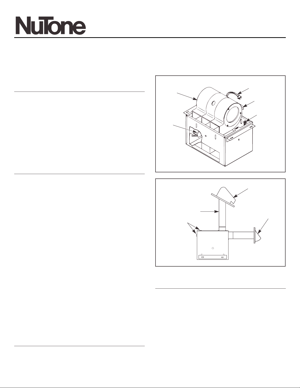
Refer to Figure 1.
1. Remove power unit from housing assembly.
(a) If necessary, unplug power plug from the connector.
(b) Loosen wing nut on hanger rods that hold the power unit.
(c) Unfasten hanger rods from slots and remove power unit.
(d) Set power unit aside until needed.
2. Refer to Figure 2. Remove one of the wiring knockouts from the
housing.
3. The ventilators can be ducted for either vertical or horizontal
discharge.
4. Refer to Figure 3. Mount 3
1
⁄4" x 10" damper section on top of
housing for vertical discharge or on the side of housing for
horizontal discharge with two (2) screws furnished.
FIGURE 1
FIGURE 2
POWER
UNIT
ROOF CAP
VERTICAL
DISCHARGE
31⁄4" x 10"
DUCT
KNOCKOUTS
FAN
HOUSING
HORIZONTAL
DISCHARGE
WALL CAP
POWER
CONNECTOR
SLOTS
WING NUT,
HANGER ROD
HANGER
ROD
Page 2
MOUNTING THE HOUSING
NOTE: These ventilators are designed for installation
between 16" O.C. ceiling joists with no framing necessary.
If the building structure has 24" O.C. joists construction,
framing will be required.
1. Position housing between ceiling joists and adjust height
to finished ceiling. Loosen two (2) hex nuts for each mounting
bracket from inside the housing and make the adjustment.
Tighten the four (4) hex nuts.
NOTE: There are four (4) additional mounting slots in the
housing for mounting or relocating the mounting brackets.
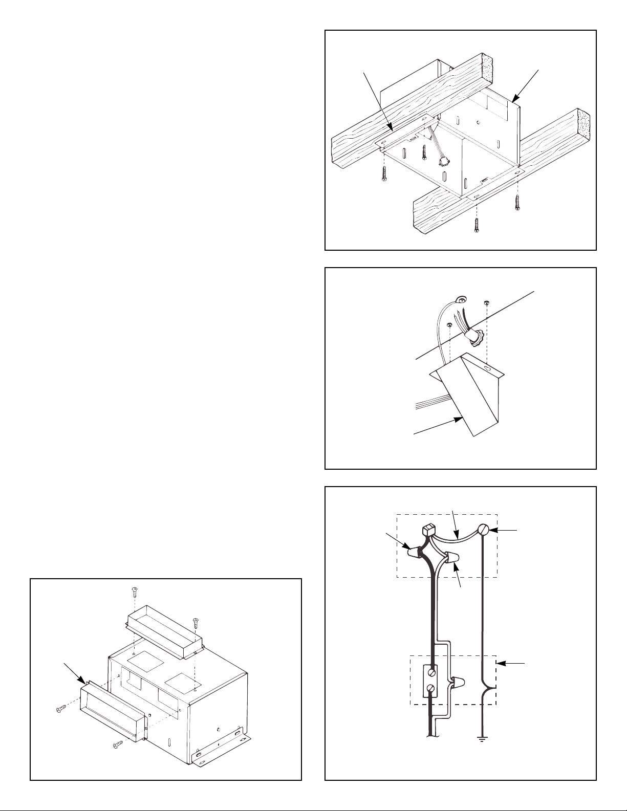
2. Refer to Figure 4. Screw housing to joists using holes
in mounting brackets and four (4) screws furnished.
3. Install standard 3
1
⁄4" x 10" ductwork from damper section
to outside wall or through roof and mount appropriate wall or roof
cap (optional.) Refer to the instructions provided with the caps.
IMPORTANT: Be certain there are not any obstructions at
the discharge of the ventilator. Be certain insulation does not
get into the ductwork or into the blower.
WIRING
NOTE: All wiring connections must comply with local codes,
ordinances and the National Electrical Code and the ventilator
must be properly grounded. Disconnect power at circuit
breaker before making wire connections.
1. Refer to Figure 5. Loosen screws and remove junction box.
2. Run 120vAC supply wiring with ground through switch box to
knockout in ventilator housing and secure with box connector.
3. Refer to Figure 6. Connect supply wires to ventilator wires: black
to black, white to white. Connect ground wire to green ground
screw.
4. Replace junction box and tighten screws.
5. Connect supply wire to switch. NOTE: Switch must be
purchased separately. Refer to NuTone's catalog.
POWER UNIT INSTALLATION
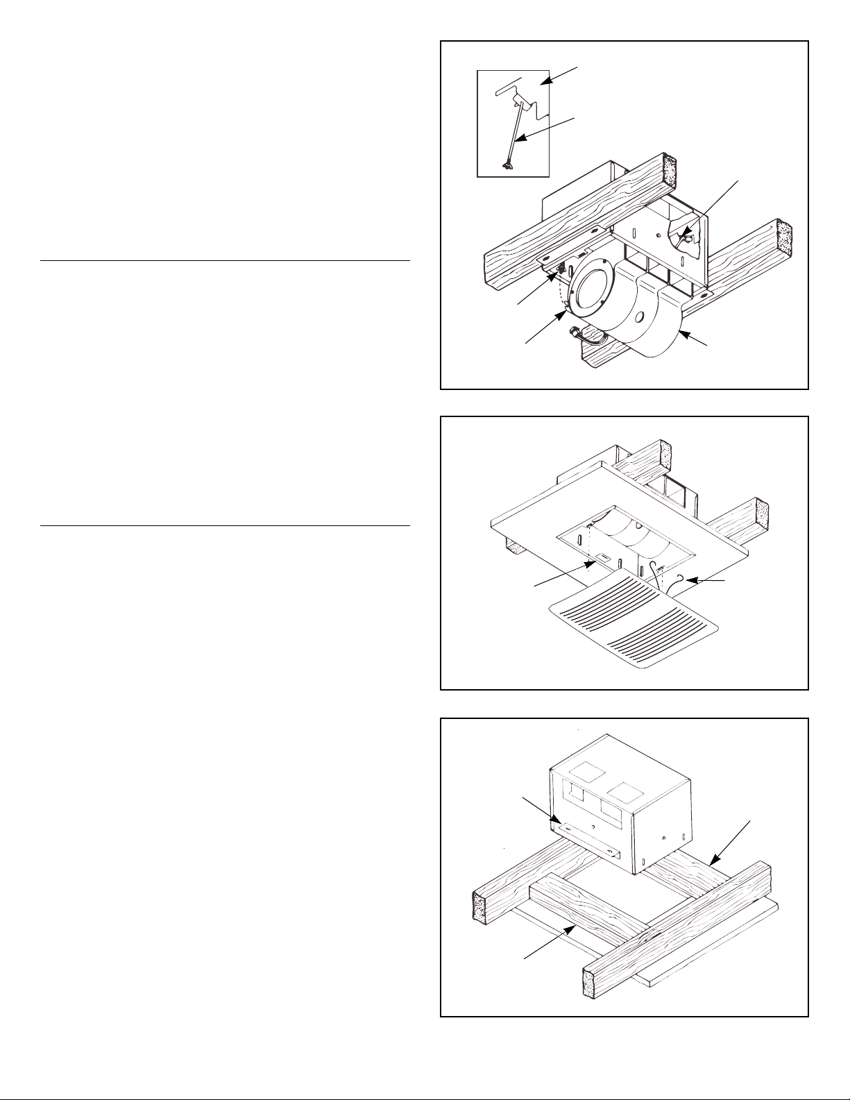
1. Refer to Figure 7. The power unit mounts with two hanger rods
to the mounting brackets. Insert the hanger rods through the
holes in the mounting bracket hooking them from the inside
to the outside.
2. Position the power unit so that its discharge opening is in line
with the installed ductwork. Hold the power unit in position
between the mounting brackets and swing the hanger rods
into the slots on the power unit and securely tighten the wing nuts.
3. Plug the three (3) wire connectors from the junction box
into the wire receptacle connector from the power unit making
sure the plug is properly aligned.
FIGURE 4
FIGURE 5
FIGURE 6
MOUNTING
BRACKET
VENTILATOR
HOUSING
JUNCTION
BOX
GREEN
GREEN
GROUND
SCREW
WHITE
SWITCH
BOX
120vAC, 60 Hz
HOUSE POWER
STANDARD
WALL SWITCH
EARTH
GROUND
BLACK
FIGURE 3
VERTICAL DISCHARGE
31⁄4" x 10" DAMPER SECTION
31⁄4" x 10"
DAMPER
SECTION
HORIZONTAL
DISCHARGE
Page 3
GRILLE INSTALLATION
1. Refer to Figure 8. Compress grille mounting springs
and insert into slots in the housing.
2. Press grille firmly into place against ceiling.
MAINTENANCE
•
WARNING: Risk of fire or electrical shock; disconnect the power
before cleaning or performing any maintenance on the ventilator.
•
If the grille becomes soiled, use only a mild soap and water
solution for cleaning. Do not use solvents or abrasive cleaners.
INSTALLATION IN
EXISTING CONSTRUCTION
Installing a ventilator in an existing construction site requires
at least a small accessible area (attic or crawl space) above
the planned installation location.
Review “INSTALLATION IN A NEW CONSTRUCTION SITE”
and follow all instructions which apply to your installation.
Locate the ventilator next to a ceiling joist.
Plan the ductwork and wiring before proceeding with the
installation.
CAUTION: Check the area above the planned installation
to be certain that:
1. Ductwork can be installed or that the area is sufficient
for proper mounting.
2. Wiring can be run to the planned location.
3. No wiring or other obstruction will interfere with the installation.
INSTALLATION FROM ACCESSIBLE
AREA ABOVE (using headers)
1. From below the installation site, drill a small hole in ceiling at
the planned location.
2. Locate hole in attic or crawl space.
3. In attic or crawl space, mark ceiling for cutout by using the
housing as a template. Cutout dimensions: 10
3
⁄16" x 141⁄2".
The short side (10
3
⁄
16
") of the cutout must be right next to
the ceiling joist.
4. Refer to Figure 9. Mark cutout along marked line.
NOTE: If ceiling is plaster, cutout should be made from
below to avoid chipping plaster.
5. Install headers between joists using nails or screws leaving
10
3
⁄16" between them.
6. Install brackets upside down on housing's long dimension using
hex nuts.
7. Mount damper section to housing, install housing and connect
wiring and ductwork. Install power unit/blower assembly and grille.
FIGURE 7
FIGURE 8
FIGURE 9
MOUNTING
BRACKET
HOOK HANGER
RODS FROM INSIDE
TO OUTSIDE
HANGER ROD
POWER UNIT
SLOT
HANGER
ROD
MOUNTING
SPRING
MOUNTING
BRACKET
HEADER
HEADER
SPRING
MOUNTING
CLIP
Page 4

INSTRUCTIONS D'INSTALLATION
LIRE ET CONSERVER CES INSTRUCTIONS
®
•
Convient pour utilisation avec commande de vitesse à
semi-conducteurs.
•
Utilisent une gaine standard de 31⁄4po x 10 po.
•
Concus pour une installation au plafond.
•
Ne pas installer au-dessus d'une baignoire ou au plafond
d'une cabine de douche.
•
Ne pas utiliser dans une cuisine.
•
Le ventilateur comprend: le boîtier, les pattes de fixation, le boîtier
de raccordement, l'ensemble bloc-moteur/rotors, le registre
et la grille.
LE VENTILATURE NE DOIT PAS ETRE INSTALLE DANS UN
PLAFOND A ISOLATION THERMIQUE SUPERIEURE A R-40.
POUR DE MEILLEURS RESULTATS
Lorsqu'on installe le ventilateur dans une construction neuve,
installer le boîtier avant de procéder aux finitions. Le bloc-moteur
et la grille doivent être installés après la finition du plafond.
Pour installer le ventilateur dans une construction ancienne,
un espace accessible au-dessus de l'emplacement choisi pour
l'installation est exigé (grenier ou combles.)
INSTALLATION DANS
UNE CONSTRUCTION NEUVE
PREPARATION
ATTENTION: Lors de la manipulation du bloc-moteur, ne pas
le soulever par les côtés pour ne pas plier les aubes.
Voir Figure 1.
1. Enlever le bloc-moteur du boîtier.
(a) Au besoin, débrancher le raccord du boîtier de raccordement.
(b) Desserrer les écrous à oreilles des tiges de suspension
qui retiennent le bloc-moteur.
(c) Enlever les tiges de suspension des fentes et déposer
le bloc-moteur.
(d) Mette le bloc-moteur de côté.
2. Voir Figure 2. Enlever une des prédécoupes pour le câblage.
3. Les ventilateurs sont prévus pour une évacuation verticale
ou horizontale.
4. Voir Figure 3. A l'aide des deux (2) vis fournies, monter
le registre de 3
1
⁄4po x 10 po en haut du boîtier pour une
évacuation verticale, ou sur le côté du boîtier pour une
évacuation horizontale.
Ventilateur QuieTTest
®
à rotor double
MODELES: QT130, QT200 & QT300
Pour plafond
FIGURE 1
FIGURE 2
BLOC-MOTEUR
CHAPERON DE TOIT
EVACUATION
VERTICALE
GAINE DE
31⁄4PO x 10 PO
PREDE COUPES
BOITIER DU
VENTILATEUR
EVACUATION
HORIZONTALE
CHAPERON
MURAL
RACCORD
D'ALIMENTATION
FENTE
ECROU A
OREILLES
SUR TIGE DE
SUSPENSION
TIGE DE
SUSPENSION
FIGURE 3
EVACUATION VERTICALE
REGISTRE DE 31⁄4PO x 10 PO
REGISTRE DE
3
1
⁄4PO x 10 PO
EVACUATION
HORIZONTALE
Page 5

MONTAGE DU BOITIER
REMARQUE: Ces ventilateurs sont conçus pour une
installation sans encadrement entre solives de 16 po d'axe
en axe. Si la structure du bâtiment comporte des solives
de 24 po d'axe en axe, un encadrement ser a nécessaire.
1. Placer le boîtier entre les solives de telle manière qu'il vienne
à ras du plafond quand celui-ci sera fini. Desserrer les deux (2)
écrous hexagonaux de chaque patte de fixation depuis l'intérieur
du boîtier et ajuster celui-ci. Serrer les quatre (4) écrous
hexagonaux.
REMARQUE: Il y a quatre (4) fentes de montage
supplémentaires sur le boîtier pour les pattes de fixation.
2. Voir Figure 4. Fixer le boîtier aux solives en faisant passer les
quatre (4) vis (fournles) par les orifices des pattes de fixation.
3. Faire passer la gaine standard de 3
1
⁄4po x 10 po du registre
au mur extérieur ou à travers le toit, et monter un chaperon mural
ou de toit (en option.) Voir les instructions comprises avec les
chaperons.
IMPORTANT: S'assurer que rien ne gêne l'évacuation
du ventilateur. S'assurer aussi qu'aucun élément d'isolation
ne pénètre dans la gaine ou dans un des rotors.
CABLAGE
REMARQUE: Tous les raccords de câblage doivent
respecter les règlements locaux et le ventilateur doit être
convenablement relié à la terre. Couper le courant avant
de faire les raccords de câblage.
1. Voir Figure 5. Enlever les vis et ôter le boîtier de raccordement.
2. Faire passer un câble de 120vCA avec terre du boîtier de
l'interrupteur au raccord du boîtier de raccordement en passant
par la prédécoupe.
3. Voir Figure 6. Raccorder les fils d'alimentation aux fils
du ventilateur: le noir avec le noir, le blanc avec le blanc.
Raccorder le fil de terre à la vis verte de mise à la terre.
4. Replacer le boîtier de raccordement et serrer les vis.
5. Raccorder le câble d'alimentation à l'interrupteur.
REMARQUE: l'interrupteur doit être acheté séparément.
Voir le catalogue NuTone.
INSTALLATION DU BLOC-MOTEUR
1. Voir Figure 7. Le bloc-moteur s'installe à l'aide de deux tiges
de suspension aux supports de montage. Insérer les tiges
de suspension par les orifices du support de montage en
les accrochant de l'intérieur vers l'extérieur.
2. Placer le bloc-moteur de manière à ce que son ouverture
d'évacuation soit alignée avec la gaine installée. Maintenir le
bloc-moteur en place entre les supports de montage et faire
basculer les tiges de suspension dans les fentes du bloc-moteur
et serrer les écrous à oreilles.
3. Brancher le raccord à trois (3) fils provenant du boîtier
de raccordement avec le raccord à trois fils du bloc-moteur
en s'assurant que le branchement soit bien fait.
FIGURE 4
FIGURE 5
FIGURE 6
PATTE DE
FIXATION
BOITIER DU
VENTILATEUR
BOITIER DE
RACCORDEMENT
VERT
VIS VERTE
DE MISE A
LA TERRE
BLANC
BOITIER
D'INTERRUPTEUR
COURANT DOMESTIQUE
120vCA, 60 Hz
INTERRUPTEUR
MURAL
STANDARD
TERRE
NOIR
Page 6

INSTALLATION DE LA GRILLE
1. Voir Figure 8. Comprimer les ressorts de montage de la grille
et les insérer dans les fentes du boîtier.
2. Appuyer fermement sur la grille pour qu'elle vienne contre
le plafond.
ENTRETIEN
•
ATTENTION: Risque d'incendie ou de décharge électrique;
couper le courant avant le nettoyage ou l'entretien du ventilateur.
•
Si la grille se salit, n'utiliser qu'une solution d'eau et de savon
doux pour le nettoyage. Ne pas utiliser de solvant ou de nettoyant
abrasif.
INSTALLATION DANS
UNE CONSTRUCTION ANCIENNE
Pour installer le ventilateur dans une construction ancienne,
un espace (même petit) accessible au-dessus de l'emplacement
choisi pour l'installation est exigé (grenier ou combles.)
Revoir le paragraphe “INSTALLATION DANS UNE
CONSTRUCTION NEUVE” er suivre toutes les instructions.
Placer le ventilateur près d'une solive.
Prévoir le gainage et le câblage avant de commencer
l'installation.
ATTENTION: Inspecter l'espace au-dessus de l'emplacement
prévu pour s'assurer que:
1. La gaine puisse être installée ou que l'espace soit suffisant
pour une installation adéquate.
2. Le câble puisse être amené jusqu'à l'emplacement choisi.
3. Aucun câblage ou autre construction ne gêne l'installation.
INSTALLATION PAR L'ESPACE
ACCESSIBLE AU-DESSUS
(en utilisant des cheviêtres)
1. Par en dessous, percer un trou une petite dans le plafond
à l'emplacement prévu.
2. Localiser le trou dans le grenier ou sous les combles.
3. Dans le grenier ou sous les combles, tracer la découpe en
utilisant le boîtier comme gabarit. Découper aux dimensions:
10
3
⁄16po x 141⁄2po. La largeur (103⁄16po) de la découpe doit être
tout contre la solive.
4. Voir Figure 9. Découper en suivant les lignes.
REMARQUE: Si le plafond est en plâtre, la découpe doit
se faire par en dessous pour éviter d'ébrécher le plâtre.
5. Installer les chevêtres entre les solives à l'aide de clous
ou de vis en laissant 10
3
⁄16po d'espace entre eux.
6. Monter les pattes à l'envers sur la longueur du boîtier en utilisant
les écrous.
7. Monter le registre sur le boîtier, installer le boîtier et raccorder
le câblage et la gaine. Installer le bloc-moteur et la grille.
FIGURE 7
FIGURE 8
FIGURE 9
SUPPORT DE
MONTAGE
ACCROCHER LA TIGE DE
SUSPENSION DE L'INTERIEUR
VERS L'EXTERIEUR
TIGE DE
SUSPENSION
BLOC-MOTEUR
FENTE
TIGE DE
SUSPENSION
PATTE DE
FIXATION
CHEVETRE
CHEVETRE
RESSORT DE
MONTAGE
SPRING
MOUNTING
CLIP
Page 7

4820 Red Bank Road, Cincinnati Ohio 45227
1140 Tristar Drive, Mississauga, Ontario, Canada L5T 1H9
Printed in U.S.A., Imprimé aux E.U., Rev. 05/2001, Part No. 85669
Garantie limitée d’un an
GARANTIE DU PROPRIÉTAIRE: NuTone garantie à l'acheteur original de ses produits que ces derniers seront exempts de tout défaut de matériaux et de fabrication pour une période
d’un (1) an à compter de la date d'achat. AUCUNE AUTRE GARANTIE, IMPLICITE OU EXPRESSE, N'EST DONNÉE, Y COMPRIS, MAIS SANS S'Y LIMITER, GARANTIE DE
MARCHANDIBILITÉ OU D'ADAPTATION À UN USAGE PARTICULIER.
Pendant cette période d’un an, NuTone procédera au remplacement ou à la réparation sans aucuns frais, mais à sa propre discrétion, de tout produit ou pièce jugé défectueux dans
le cadre d'une utilisation normale. CETTE GARANTIE NE VISE PAS LES DISPOSITIFS D'AMORÇAGE NI LES TUBES DES LUMINAIRES FLUORESCENTS. Cette garantie ne
couvre pas (a) l'entretien et le service courants ni (b) les produits et les pièces ayant fait l'objet d'un usage abusif, de négligence, d'un accident, d'un entretien ou d'une réparation non
appropriée (par du personnel non autorisé par NuTone), d'une mauvaise installation ou d'une installation non conforme aux directives d'installation fournies.
La durée de toute garantie implicite est limitée à la période de deux ans précisée pour la garantie expresse. Certains états ne reconnaissent pas les restrictions relatives à la durée des
garanties implicites; il se pourrait donc que cette restriction ne s'applique pas dans votre cas.
LE REMPLACEMENT OU LA RÉPARATION PAR NUTONE, À SA PROPRE DISCRÉTION, DE TOUT PRODUIT OU PIÈCE DÉFECTUEUX CONSTITUE LE SEUL REMÈDE DE
L'ACHETEUR EN VERTU DE CETTE GARANTIE. NUTONE NE PEUT ÊTRE TENUE RESPONSABLE DES DOMMAGES INDIRECTS, CONSÉCUTIFS OU SPÉCIAUX
ATTRIBUABLES À L'UTILISATION OU AU RENDEMENT DU PRODUIT. Certains états ne reconnaissent pas les restrictions ni les exclusions relatives aux dommages indirects,
consécutifs ou spéciaux; il se pourrait donc que cette restriction ne s'applique pas dans votre cas. La présente garantie vous accorde des droits spécifiques, mais vous pourriez aussi
avoir d'autres droits en fonction de l'état dans lequel vous résidez. Cette garantie remplace toute autre garantie donnée précédemment.
SERVICE SOUS GARANTIE Pour être admissible au service sous garantie, vous devez (a) aviser NuTone, à l'adresse fournie ci-dessous ou par téléphone au 1 800 5433687, (b) fournir le numéro du modèle et la description de la pièce et (c) décrire la nature du défaut de la pièce ou du produit. Au moment de la demande de service sous
garantie, vous devez fournir une preuve de la date d'achat originale.
Date d’installation Entrepreneur ou installateur
N° de modèle et description du produit
POUR OBTENIR DE L’ASSISTANCE OU DU SERVICE:
Pour connaître le Centre de service NuTone autorisé indépendant le plus proche:
Résidents des États-Unis continentaux, composez le numéro sans frais: 1 800 543 8687
Garder à protée de la main le numéro du modèle, la date et la preuve d’achat, le type de problème.
Résidents de l’Alaska et d’Hawaii: Écrivez à NuTone Inc. Attn: Department of National Field Service, 4820 Red Bank Road, Cincinnati Ohio USA 45227-1599.
Résidents du Canada: Écrivez à Broan-NuTone Canada, 1140 Tristar Drive, Mississauga, Ontario Canada L5T 1H9.
Rev. 03/2001
Product specifications subject to change without notice.
Les caractéristiques de produits peuvent changer sans prévis.
One Year Limited Warranty
WARRANTY OWNER: NuTone warrants to the original consumer purchaser of its products that such products will be free from defects in materials or workmanship for a period
of one (1) year from the date of original purchase. THERE ARE NO OTHER WARRANTIES, EXPRESS OR IMPLIED, INCLUDING, BUT NOT LIMITED TO, IMPLIED
WARRANTIES OF MERCHANTABILITY OR FITNESS FOR A PARTICULAR PURPOSE.
During this one year period, NuTone will, at its option, repair or replace, without charge, any product or part which is found to be defective under normal use and service.
THIS WARRANTY DOES NOT EXTEND TO FLUORESCENT LAMP STARTERS OR TUBES, FILTERS, DUCT, ROOF CAPS, WALL CAPS AND OTHER ACCESSORIES
FOR DUCTING. This warranty does not cover (a) normal maintenance and service or (b) any products or parts which have been subject to misuse, negligence, accident,
improper maintenance or repair (other than by NuTone), faulty installation or installation contrary to recommended installation instructions.
The duration of any implied warranty is limited to the one year period as specified for the express warranty. Some states do not allow limitation on how long an implied warranty
lasts, so the above limitation may not apply to you.
NUTONE’S OBLIGATION TO REPAIR OR REPLACE, AT NUTONE’S OPTION, SHALL BE THE PURCHASER’S SOLE AND EXCLUSIVE REMEDY UNDER THIS
WARRANTY. NUTONE SHALL NOT BE LIABLE FOR INCIDENTAL, CONSEQUENTIAL OR SPECIAL DAMAGES ARISING OUT OF OR IN CONNECTION WITH
PRODUCT USE OR PERFORMANCE. Some states do not allow the exclusion or limitation of incidental or consequential damages, so the above limitation or exclusion may
not apply to you. This warranty gives you specific legal rights, and you may also have other rights, which vary from state to state. This warranty supersedes all prior warranties.
WARRANTY SERVICE: To qualify for warranty service, you must (a) notify NuTone at the address stated below or telephone 1/800-543-8687, (b) give the model
number and part identification and (c) describe the nature of any defect in the product or part. At the time of requesting warranty service, you must present
evidence of the original purchase date.
Date of Installation Builder or Installer
Model No. and Product Description
IF YOU NEED ASSISTANCE OR SERVICE:
For the location of your nearest NuTone Independent Authorized Service Center:
Residents of the contiguous United States Dial Free 1-800-543-8687
Please be prepared to provide:
Product model number • Date and Proof of purchase • The nature of the difficulty
Residents of Alaska or Hawaii should write to: NuTone Inc. Attn: Department of National Field Service, 4820 Red Bank Road, Cincinnati Ohio 45227-1599.
Residents of Canada should write to: Broan-NuTone Canada, 1140 Tristar Drive, Mississauga, Ontario, Canada L5T 1H9.
Rev. 03/2001
 Loading...