

Page 1
INSTALLATION GUIDE
CENTRAL VACUUM POWER UNITS
PUREPOWER SERIES
PP5501, PP6501 & PP7001
AB0039
!
FOR RESIDENTIAL USE ONLY
BROAN-NUTONE LLC; HARTFORD, WISCONSIN WWW.NUTONE.COM 1-888-336-3948
R
EGISTER YOUR PRODUCT ONLINE AT : WWW.NUTONE.COM/REGISTER
MODELS SFDB-DQ, SFDB-DR AND SFDB-DS
!
24010 rev. B
Page 2

IMPORTANT SAFETY INSTRUCTIONS
SAVE THESE INSTRUCTIONS
READ ALL INSTRUCTIONS BEFORE USING THIS APPLIANCE
When using an electrical appliance, basic precautions should always be followed, including the following:
WARNING
!
To reduce the risk of fire, electric shock or injury:
1. Do not use on wet surfaces or outdoors.
2. Do not vacuum liquids or fine powders (such as drywall dust).
3. Do not use to pick up flammable or combustible liquids such
as gasoline or use in areas where they may be present.
4. Do not pick up anything that is burning or smoking, such as
cigarettes, matches, or hot ashes.
5. Do not allow to be used as a toy. Close attention is necessary
when used by or near children.
6. Use only as described in this manual. Use only
manufacturer's recommended attachments.
7. Keep hair, loose clothing, fingers and all parts of body away
from openings and moving parts.
8. Turn off all controls before unplugging.
9. Use extra care when cleaning on stairs.
10. Do not handle plug or appliance with wet hands.
11. Do not use with damaged cord or plug. If appliance is not
working as it should, if it has been dropped, damaged,
left outdoors, or dropped into water, return it to a Service
Center.
12. Keep your work area well lighted.
13. Connect to a properly grounded outlet only. See grounding
instructions shown on page 10.
14. When performing installation, servicing or cleaning the unit,
it is recommended to wear safety glasses and gloves.
CAUTION
1. Do not put any object into openings. Do not use with any
opening blocked; keep free of dust, lint, hair and anything
that may reduce air flow.
2. Ensure air flows freely and exhausts unobstructed from top
or side outlet.
3. Do not use without filter (or filters, according to the model)
in place.
4. Do not use to blow leaves or debris.
5. Do not place any object on top of the unit.
6. Do not install the unit horizontally.
7. Do not use the pail as a wash bucket.
8. Do not use the pail as a stool.
9. Avoid picking up sharp objects.
10. This appliance is for use on a standard 120 VAC, dedicated
20-amp branch circuit.
11. Do not unplug the unit by pulling on cord. To unplug, grasp
the plug, not the cord.
12. Store your vacuum cleaner indoors in a clean, dry area, and
away from extreme temperatures.
13. Any servicing other than that recommended in this manual
should be performed by an authorized service facility.
14. We recommend that your unit be inspected by a specialized
technician once a year.
2
Page 3

TABLE OF CONTENTS
SYSTEM PLANNING LAYOUT . . . . . . . . . . . . . . . . . . . . . . . . . . . . . . . 4-5
THE RANCH STYLE HOUSE . . . . . . . . . . . . . . . . . . . . . . . . . . . . . . . . . . . . . . . . . . . . . 4
T
HE TWO-STORY HOUSE . . . . . . . . . . . . . . . . . . . . . . . . . . . . . . . . . . . . . . . . . . . . . . 4
THE SPLIT-LEVEL HOUSE. . . . . . . . . . . . . . . . . . . . . . . . . . . . . . . . . . . . . . . . . . . . . . 4
LOCATING THE POWER UNIT . . . . . . . . . . . . . . . . . . . . . . . . . . . . . . . . . . . . . . . . . . . . 5
THE RANCH STYLE HOUSE . . . . . . . . . . . . . . . . . . . . . . . . . . . . . . . . . . . . . . . . . . . . . 5
TUBING AND WALL INLET LOCATIONS . . . . . . . . . . . . . . . . . . . . . . . . . . . . . . . . . . . . . . . . . 5
GENERAL INSTALLATION GUIDE . . . . . . . . . . . . . . . . . . . . . . . . . . . . . 5-6
TOOL LISTING . . . . . . . . . . . . . . . . . . . . . . . . . . . . . . . . . . . . . . . . . . . . . . . . . . . 5
WORKING WITH PLASTIC TUBING. . . . . . . . . . . . . . . . . . . . . . . . . . . . . . . . . . . . . . . . . . 5-6
INSTALLATION IN NEW CONSTRUCTION. . . . . . . . . . . . . . . . . . . . . . . . . 7-10
WALL INLET ROUGH-IN. . . . . . . . . . . . . . . . . . . . . . . . . . . . . . . . . . . . . . . . . . . . . . . 7
INSTALLING THE TUBING. . . . . . . . . . . . . . . . . . . . . . . . . . . . . . . . . . . . . . . . . . . . . . . 8
WALL INLET INSTALLATION . . . . . . . . . . . . . . . . . . . . . . . . . . . . . . . . . . . . . . . . . . . . . 9
CI399 ELECTRAVALVE™ ELECTRIFIED INLET INSTALLATION (CI399RK ROUGH-IN). . . . . . . . . . . . . . . . . . . . 10
CI1358 SUPERVALVE™ WALL INLET & ROUGH-IN KIT . . . . . . . . . . . . . . . . . . 11
INSTALLATION IN EXISTING CONSTRUCTION . . . . . . . . . . . . . . . . . . . . . 12-18
LOCATING ACCESS KEYS IN EXISTING CONSTRUCTION . . . . . . . . . . . . . . . . . . . . . . . . . . . . . . . . . 12
AVOIDING IN-WALL OBSTACLES . . . . . . . . . . . . . . . . . . . . . . . . . . . . . . . . . . . . . . . . . . . 12
INSTALLING THE INLET TUBING . . . . . . . . . . . . . . . . . . . . . . . . . . . . . . . . . . . . . . . . . . 12-14
WALL INLET INSTALLATION . . . . . . . . . . . . . . . . . . . . . . . . . . . . . . . . . . . . . . . . . . . 14-16
C370 OR 360 SERIES INLETS (CF361 OR CF361F ROUGH-IN) . . . . . . . . . . . . . . . . . . . . . . . . . 16-17
MODEL 330 SERIES WALL INLET INSTALLATION (CF329 ROUGH-IN) . . . . . . . . . . . . . . . . . . . . . . . . 17-18
FLOOR INLET INSTALLATION IN NEW AND EXISTING CONSTRUCTION . . . . . . . . . . . . . . . . . . . . . . . . . . . 18
CI377W CANSWEEP® UNDER CABINET INSTALLATION. . . . . . . . . . . . . . . . 19-20
CI377W CANSWEEP® BASEBOARD WALL INSTALLATION . . . . . . . . . . . . . . . . 21
ASSEMBLING THE TUBING SYSTEM . . . . . . . . . . . . . . . . . . . . . . . . . . 22-24
POWER UNIT INSTALLATION . . . . . . . . . . . . . . . . . . . . . . . . . . . . . . 25-27
CHANGING INTAKE LINE DIRECTION . . . . . . . . . . . . . . . . . . . . . . . . . . . . . . . . . . . . . . . . . 25
CONVERTING POWER UNIT FROM CYCLONIC OPERATION TO A BAGGED SYSTEM (DEBRIS BAG INCLUDED) . . . . . . . . . . 25
MOUNTING THE POWER UNIT . . . . . . . . . . . . . . . . . . . . . . . . . . . . . . . . . . . . . . . . . . . . 26
FITTING MAIN LINE TO POWER UNIT . . . . . . . . . . . . . . . . . . . . . . . . . . . . . . . . . . . . . . . . . 27
GROUNDING INSTRUCTIONS . . . . . . . . . . . . . . . . . . . . . . . . . . . . . . . . 27
WIRING . . . . . . . . . . . . . . . . . . . . . . . . . . . . . . . . . . . . . . . . . . . . . . . . . . . . . . 27
FINAL SYSTEM CHECK. . . . . . . . . . . . . . . . . . . . . . . . . . . . . . . . . . . . 28
WARRANTY . . . . . . . . . . . . . . . . . . . . . . . . . . . . . . . . . . . . . . . . . . 28
TROUBLESHOOTING GUIDE. . . . . . . . . . . . . . . . . . . . . . . . . . . . . . . . . 29
SERVICE PARTS . . . . . . . . . . . . . . . . . . . . . . . . . . . . . . . . . . . . . . . 30
3
Page 4
SYSTEM PLANNING AND LAYOUT
T
The NuTone central cleaning system consists of a power unit, PVC tubing and fittings, wall inlets, a flexible hose and various
cleaning attachments.
The power unit is designed to be wall-mounted away from the living area of the home and connected to the living area by means
of permanently installed in-wall tubing, fittings and inlets.
Generally, an installation will require 3 to 4 inlets and 16 to 20 feet of tubing per inlet. It is suggested that a floor plan be used to
more accurately determine the quantity of materials needed.
Use the following examples as an aid in planning the installation in either new or existing construction. You should be able to
adapt the examples shown to your specific home layout.
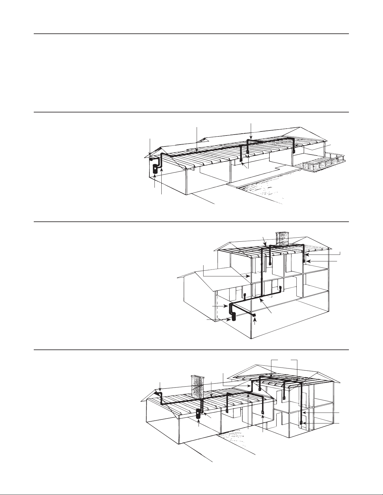
THE RANCH STYLE HOUSE
Here the power unit is mounted in the
garage. The intake and exhaust tubing,
the only exposed tubing in the installation,
EXHAUST
runs up the garage wall and into the attic.
The trunk line runs horizontally through the
attic from the power unit to the farthest inlet
location. Branch lines spread throughout
the attic, connecting the trunk line to the
inlet tubing. Each inlet tube is threaded
vertically through an inside wall. Located in
hallways and in large rooms, the inlets are
placed to provide maximum access to all
POWER
UNIT
INTAKE
cleaning areas. See figure at right.
AH0003A
THE TWO-STORY HOUSE
A double-trunk line system is commonly used in two-story
houses. In the installation shown at right, the power unit
is mounted in the basement. The intake tubing runs up
the basement wall and connects to the main trunk line,
which runs along the unfinished basement ceiling. Two
first-floor inlets are connected to the basement trunk line
by vertical inlet lines run through interior walls. In the
center of the house, a vertical branch line runs from the
basement trunk line, through stacked closets, up into the
attic. A second trunk line runs across the attic and two
branch lines connect to inlet lines which are dropped
down through upstairs interior walls. See figure at right.
THE SPLIT-LEVEL HOUSE
AH0005A
TRUNK LINE
VERTICAL
BRANCH
LINE
INTAKE
POWER
UNIT
BRANCH LINE
INLETS
AT TIC
TRUNK
LINE
EXHAUST
BASEMENT
TRUNK LINE
INLET LINE
INLET
LINE
INLE
Like the two-story house, the split level
installation commonly calls for a two-level
trunk line. Here, the power unit is located
in the garage. The intake tubing runs
exposed up the garage wall and into the
ground level section's attic. Two branch
lines connect this part of the trunk line
to inlet lines which are dropped inside
interior walls. A vertical branch line runs
to the upstairs attic, where the trunk line
branches into a T-shape. This trunk line
connects to two upstairs inlet lines and
to one inlet line which drops through an
upstairs wall and down into the third-level
utility room to service this entire level. See
figure at right.
AH0004A
EXHAUST
BRANCH
VERTICAL
BRANCH
LINE
TRUNK
LINE
POWER
UNIT
INTAKE
BRANCH
LINE
INLET
LINES
INLET
LINE
INLET
4
Page 5
SYSTEM PLANNING AND LAYOUT (CONT'D)
!
!
WARNING
Do not install outdoors. When performing
installation, servicing or cleaning the unit, it is
recommended to wear safety glasses and gloves.
LOCATING THE POWER UNIT
• Locate the power unit away from the general living area in
an accessible location for cleaning and maintenance.
• When planning the installation of PP7001 power unit,
remember it is equipped with an inlet to service a garage,
basement, utility room, etc., wherever it is located.
• Locate the power unit within 6 feet of a grounded electrical
outlet. The power unit requires a 120 VAC power source.
• Do not locate the power unit close to a source of extreme
heat (i.e.: water heater) or in an area with a high ambient
temperature (i.e.: attic, furnace room).
• If the power unit is located in a closet or a small utility
room, make sure the area is well-ventilated (e.g.: with door
louvers).
• Exhausting the power unit to the outside is recommended
for optimal performance. The exhaust should not be vented
into a wall, a ceiling or a concealed space in the house.
The exhaust line should be vented outside the home using
a Model 393 or CI330 wall caps.
TUBING AND
WALL INLET LOCATIONS
Locate inlets on interior walls, choosing central locations
which allow several rooms to be cleaned from a single inlet
using a 30-foot long hose.
The tubing installation should consist of a main trunk line
running from the farthest wall inlet to the power unit location,
with branch lines running to each additional inlet. Keep all
tubing lines as straight as possible and use as few fittings as
possible.
Beginning at the area farthest from the power unit, choose
a tentative inlet location. Measure 30 feet from the proposed
inlet location to the farthest corner of the rooms to be cleaned
by that inlet to determine if inlet location is proper. If working
from blueprints (or building plans drawn at 1⁄4" = 1 ft. scale),
use a 7½" chain as your guide to determine inlet locations.
Locate inlets within six feet of an electrical receptacle to
allow use of optional current-carrying hose.
Be sure inlets will not be blocked by doors or furniture.
Be sure inlets will not interfere with electrical, plumbing or
other mechanical installations.
Move tentative inlet location if necessary. Use the same
procedure to determine each additional inlet location,
always working toward the power unit.
GENERAL INSTALLATION GUIDE
WARNING
When applicable local regulations comprise more restrictive installation and/or certification requirements,
the aforementioned requirements prevail on those of this document and the installer agrees to conform to
these at his own expenses.
TOOL LISTING
Depending on your installation, you may require the use of these tools. The power tools are recommended to make your installation
proceed quickly. Also, plan a mask when cutting ducting (PVC dust) and gloves when using glue.
• Wire Strippers • 1/4" Drill • Level • Flashlight
• Utility Knife • Putty Knife • Drill Bit • Electrical tape
• Knife • Hammer • Screwdriver • Safety Glasses
• 2½" Hole Saw • Keyhole Saw • Wrench • Hacksaw
• 1/2" Drill • Cold Chisel • Tape Measurer
WORKING WITH PLASTIC TUBING
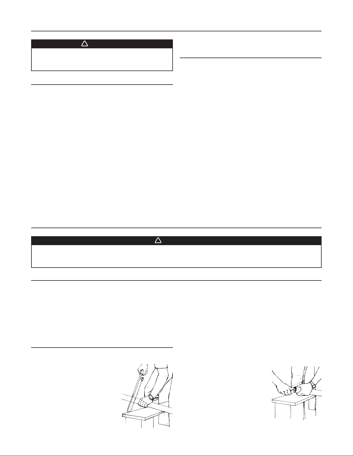
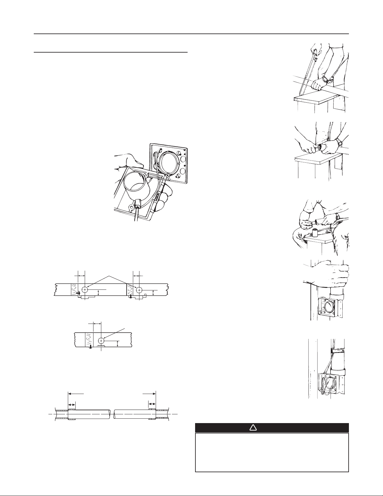
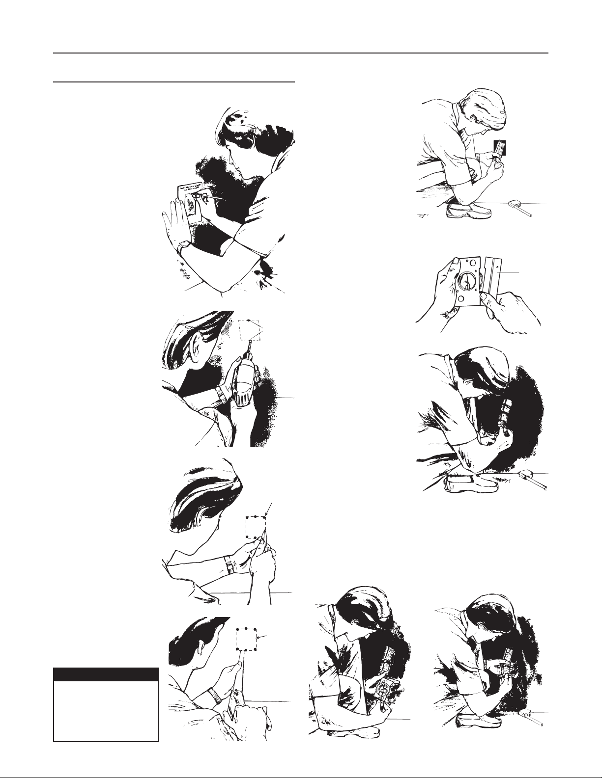
CUTTING THE TUBING
Before you cut a length of tube,
accurately measure the length you
need. Allow 5/8” of tubing for inserting
into fittings and 1½” for placing into
flexible tubing. Cut the plastic tubing
with a hacksaw, making sure that the
cut is exactly square. (You can use a
tube cutter if one is available.) Use
wire cutters or tin snips to cut flexible
tubing. The 8” lengths of flexible tubing
supplied with each inlet should not be
cut. See figure at right.
AR0016
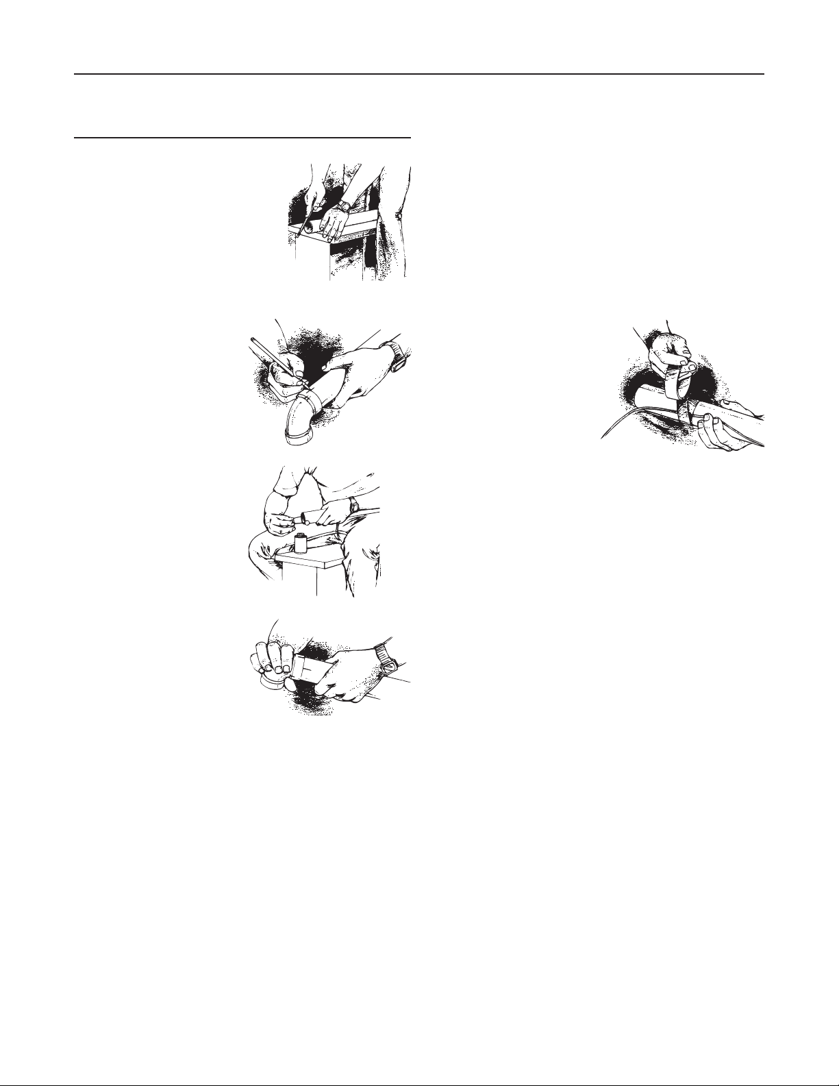
Use a small knife to remove any burrs
from the inside of the tube. You can
also use steel wool to remove burrs.
The burrs must be removed or they
may impede air flow of form clogs by
snagging hair and carpet thread. See
figure at right.
AR0017
5
Page 6
GENERAL INSTALLATION GUIDE (CONT'D)
WORKING WITH
PLASTIC TUBING (CONT'D)
CUTTING THE TUBING (CONT'D)
Next, use a file to slightly bevel the
outside of the tube so that it will easily
slide into the fitting. Use steel wool or
a light grained sandpaper to buff the
surface of the tube which will be glued.
This will clean the tube and assure a
good seal. See figure at right.
MAKING A JOINT
Insert the tube into the fitting,
aligning the two parts as they
will be installed. Mark the tube
and the fitting so that you can
quickly realign the joint. See
figure at right.
Apply cement only to the
outside of the tube. Dab the
cement generously in an
inch-wide band. Insert the
tube into the fitting with the
alignment marks a quarter turn
apart, and then quickly push
and turn the fitting to align the
marks and spread the cement.
Allow one minute for the joint to
dry. You may also use electrical
tape or duct tape to further seal
the joint. See figure at right.
AR0018
AR0019
CEMENTING FLEXIBLE TUBING
Make sure the ends of the flexible tubing are even—trim if
necessary. When you join flexible tubing to plastic tubing or to
an inlet mounting plate, apply cement to both the inside of the
flexible tubing and the outside of the plastic tubing or mounting
plate tubing ring. Twist the two pieces as you join them to
evenly spread the glue. Allow five minutes for the cement to set
in flexible tubing. You may also use electrical tape or duct tape
to further seal the joint.
SECURE WIRE TO T UBING
The low-voltage power wiring
is run along with the tubing. To
insure that the wire is secure
and will not hang-up in a wall,
use electrical tape to attach
the wire to the tubing. Tape
the wire approximately every
12-18 inches. See figure at
right.
AO0011
AO0010
6
Page 7
INSTALLATION IN NEW CONSTRUCTION
WALL INLET ROUGH-IN
Once the locations for the wall inlets have been determined, mount all inlet brackets.
Choose the appropriate mounting bracket for the inlet being installed. (See chart below.)
ROUGH-IN SERIES
395 396-3 CI3301RK CI3303RK CF329 CF361 CF361F CI399RK
330 X X X
360XX XX
CI358 Rough-in and wall valve sold together
SERIES
WALL VALVE
To locate a bracket on a wall stud, measure approximately 18" up from finished floor level. (Height may vary according to
individual preference.)
CI399 X
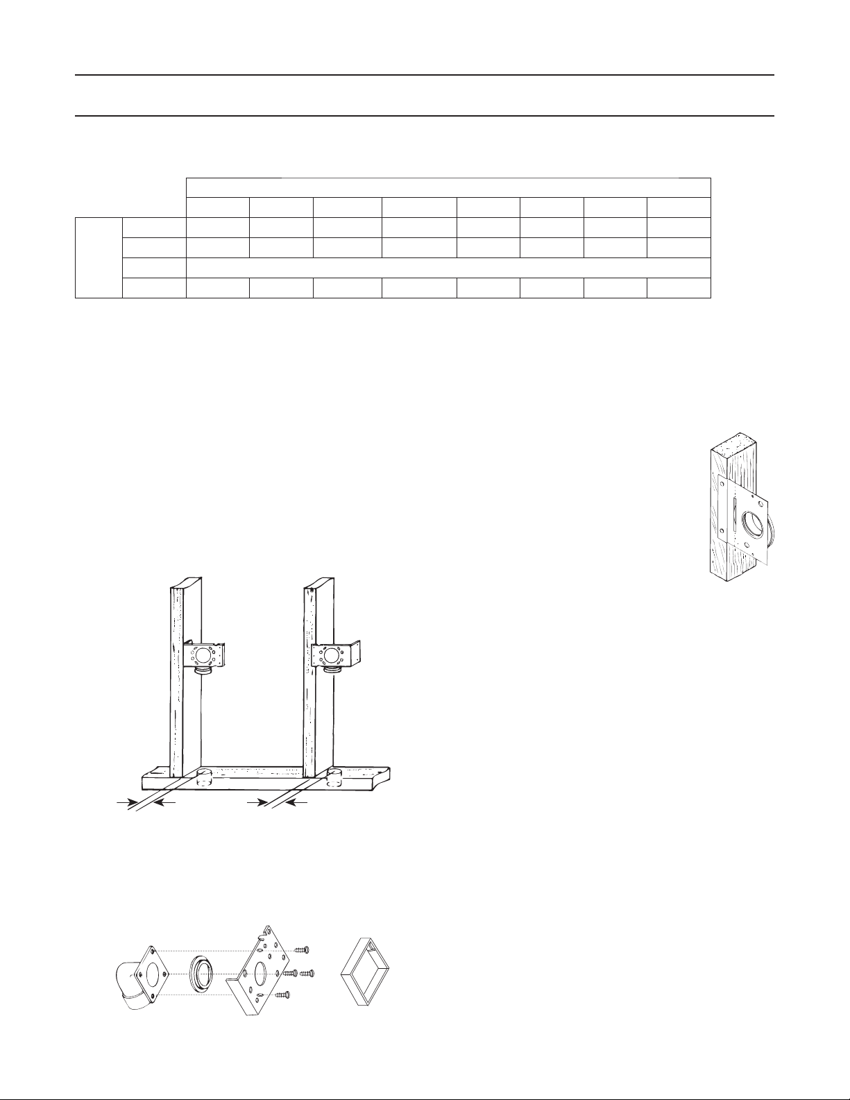
MODELS CF361 & CF361F
(FOR USE WITH 360 INLET)
Refer to figure below. Nail bracket to the side of the stud so
that the front edge of the bracket is flush to the front of the
stud. (The bracket may also be nailed to the front edge of
the stud. See face mounting illustrated. For face mounting,
use locating tabs on bracket for proper alignment.)
MODEL CF361 & CF361F
SIDE
MOUNTING
23/8"
AD0059A
FACE
MOUNTING
13
/16"
1
MODELS CF329 (FOR USE WITH 330 INLETS)
When using Model CF329, glue elbow to
mounting plate. Attach to stud as shown in
figure at right.
AD0015
Refer to figure below. Remove cardboard from plaster guard
frame. Using four (4) provided screws, attach the appropriate
flanged fitting and inlet seal to back of inlet.
Replace cardboard in plaster guard frame
AD0060
7
Page 8
INSTALLATION IN NEW CONSTRUCTION (CONT'D)
!
INSTALLING THE TUBING
Use the following installation guidelines when installing tubing.
B Start tubing installation at farthest inlet and work toward the
power unit.
C Tubing run to the power unit should be as straight as
possible.
D When assembling sections with elbows and tees, make sure
the curve in the fitting is aligned so that the air flows toward
the power unit.
E Branch lines should always join the trunk line from above
or from the same level. Never join a branch line from an
angle below the trunk line.
I Refer to figure at right. Cut tubing,
keeping cut square.
AR0016
F Refer to figure at right. Run
low voltage wiring (Model
376UL) and secure wiring
to tubing as tubing is
installed. Model CF380
Pipe Support can be used
to support long runs of
tubing (position near joists)
and to clip wire along tubing.
Secure tubing to joists or
studs. Leave approximately
6" of wire for connection to
each inlet.
G Cut a 2½" diameter hole in sole plate, header or stud
AE0040
directly in line with opening of inlet bracket fitting. See figure
below for center line dimensions.
MODEL CF361 MOUNTING
2½” DIA. HOLE
3
2
SIDE MOUNTING
AD0055A
THROUGH SOLE PLATE
”
/8
13
1
/16
MODEL CF329 MOUNTING
2”
FACE MOUNTING
”
THROUGH SOLE PLATE
13
”
1
/16
13
”
1
/16
13
1
FACE MOUNTING
2½” DIA. HOLE
”
/16
J Refer to figure at right. Remove
burrs from both inside and outside
of tubing.
AR0017
K Before cementing, pre-assemble section to inlet fitting,
check for proper length.
L Refer to figure at right Apply PVC
cement (Model 379) to outside of
tubing. Coat tubing approximately 1"
back. Take care to keep cement
from inside of tube.
AR0020
M Refer to figure at right. Insert tubing
into fitting with a twisting motion to
evenly spread cement. Be sure
tubing is firmly seated in fitting.
AO0012
N If fittings have been attached to tubing at the end opposite the
inlet bracket, be sure alignment is proper before cement sets.
H Refer to figure below. Measure length of tubing needed to
connect inlet to trunk line. Allow approximately 3⁄4" of tubing
for inserting into fittings.
INCLUDE FITTING RECESS
3/4”
(19 mm)
FITTING
AD0017A
IN MEASUREMENT
TUBING MEASUREMENT
PVC TUBING
(19 mm)
FITTING
3/4”
O Refer to figure at right. Tape wire
to tubing to hold in place and insert
through hole in inlet bracket.
AD0018
P Connect each inlet line and branch line into main trunk line.
Complete low voltage wiring as main trunk line is continued
back to power unit.
WARNING
When tubing is run through the wall stud, sole
plate, headers or else where building materials will
be attached, place a nail plate (Model 378) over that
area (on both sides if necessary) to prevent nails
from piercing tubing.
8
Page 9
INSTALLATION IN NEW CONSTRUCTION (CONT'D)
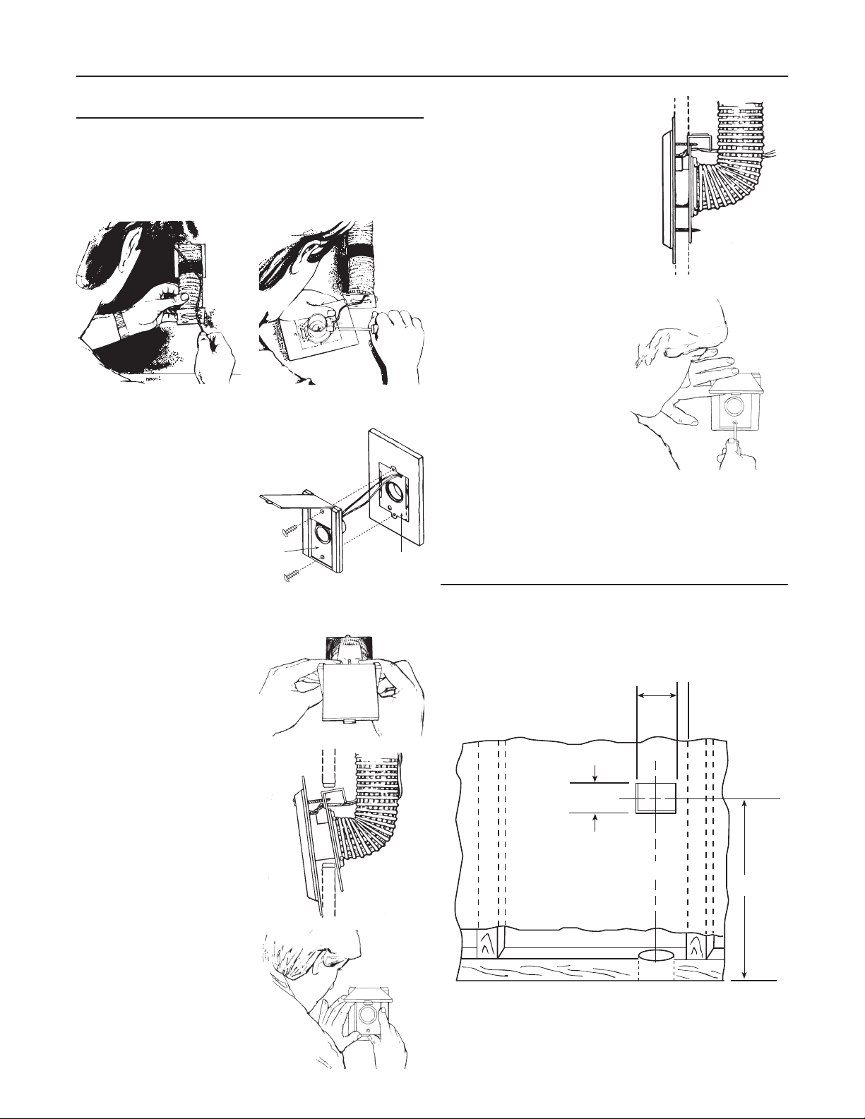
WALL INLET INSTALLATION
MODEL 360 WALL INLET
(CF361
B Remove the cardboard plaster guard.
C Refer to figure at right.
For some drywall or panel
construction, the plaster frame
will extend beyond the finished
wall. In this case, remove
plaster frame from mounting
bracket by removing mounting
screws.
NOTE: When using the model CF361 and CF361F inlet
INLET MOUNTING
AND CF361F ROUGH-INS)
AR0045
bracket on walls thinner than 1⁄2", use a 1⁄4" spacer
(not furnished) between the wall and the inlet bracket.
See figure below. Spacer may be made from plywood,
Masonite™, etc. Contact cement may be used to hold
spacer in place during assembly. Configuration of
spacer may vary depending upon installation.
BRACKET
SPACER
1/4"
WALL LESS THAN
1
/2" THICK.
MODEL 330 WALL INLET (CF329 ROUGH-IN)
B Refer to figure at right. Connect
2-conductor low-voltage wire
to terminal screws on back of
wall inlet.
C Align inlet mounting holes with
holes in mounting plate.
D Refer to figure at right. Place
inlet into mounting plate and
secure with two provided
screws.
INLET
AE0024A
MOUNTING
PLATE
21/4"
AD0057A
D Refer to figure at right.
31/4"
PLASTER
GUARD
HOLE
Connect 2-conductor low voltage wire to terminal
screws on back of wall inlet.
AE0040
E Guide excess wire back through the hole in inlet bracket and
flanged fitting.
F Refer to figure at right. Place
inlet into mounting bracket and
secure.
INLET
AE0024A
MOUNTING
PLATE
9
Page 10
INSTALLATION IN NEW CONSTRUCTION (CONT'D)
!
CI399 ELECTRAVALVE™
ELECTRIFIED INLET INSTALLATION
(CI399RK ROUGH-IN)
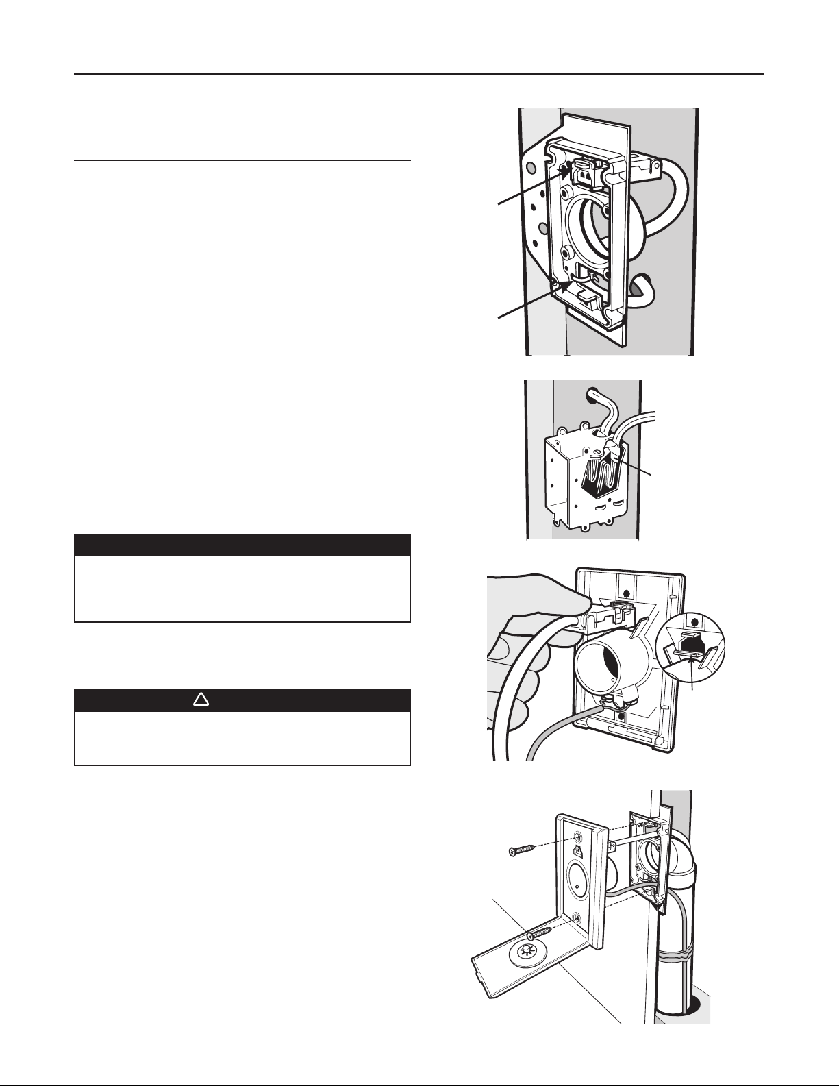
B Fasten the mounting plate onto a stud. Locate the lower hole
on the mounting plate marked “Wire Trap” and use a zip tie
to secure the wire to the back of the mounting plate at the
10” mark.
C Position the assembled wire plug through the top hole in the
mounting plate. Secure the plug to the mounting plate tab as
shown. This will keep it secure and out of harm’s way during
drywalling and finishing.
D Run the wire to the adjacent electrical box. If the
wire is to run through a stud, drill a hole directly
on the center of the stud and run the wire through.
Strip 6 inches of outer sheathing from this end of the wire and
place the wire into the electrical box through a strain relief.
Ensure the strain relief is tightened against the outer sheathing
(do not over tighten). Leave 1/2” of sheathing inside the outlet
box. Fold the 6” of black and white wires into the outlet box.
Leave the wires to be connected by the electrician when the
outlet receptacle is being installed.
E Once drywall and finishing have been completed, pull the
plug off the tab and snap into the opening on the back of the
new ElectraValve®. Ensure the plug is securely locked into
the position as shown. Attach the low voltage wires to the
screw contacts.
B
Ta b
Wire
Trap
D
C
1/2” Outer
Sheathing
CAUTION
Power tools such as routers are not recommended
for use with the inlet installation, as removal of
drywall with these devices may cause damage to
the mounting plate and/or inlet plug.
F Insert the valve into the mounting plate and secure the valve
to the mounting plate with the screws provided.
WARNING
All location and installation direct connect
electrified wall valves must conform with all local
and municipal building codes.
E
F
Low Voltage Wires
Valve
locking
tabs
AE0050A
10
Page 11
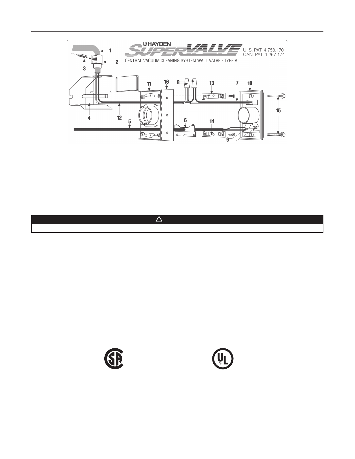
C1358 SUPERVALVE™ WALL INLET & ROUGH-IN KIT
!
AL0008A
SAFETY INSTRUCTIONS
FOR HOUSEHOLD USE ONLY. INSTALL ONLY ON A NOMINAL 120 V, 60 Hz, 7 A SUPPLY
PROTECTED BY A MAXIMUM 15 A OVERCURRENT PROTECTIVE DEVICE.
THE PIN CONNECTOR ON THIS TYPE A WALL VALVE IS INTENDED FOR USE ON
A NOMINAL 120 V, 60 Hz, 7 A SUPPLY ONLY. IT IS REQUIRED TO BE WIRED BY A
QUALIFIED ELECTRICIAN AND IS REQUIRED TO CONFIRM
TO LOCAL ELECTRICAL CODES.
WARNING
Do not operate on wet surfaces!
NEW CONSTRUCTION
Install BUILDING WIRE CONDUCTORS (1) through the approved type electrical CONNECTOR (2) (supplied) until they
B
protrude approximately six inches from connector. Seat connector firmly into the opening atop the WIRING COMPARTMENT (4).
Insert and secure LOCKING TAB (3).
C Splice wires from INLET VALVE RECEPTACLE (7) to the protruding building wire conductors with no. 31 TWIST-ON WIRE
CONNECTORS (8) (not supplied).
NOTE: WHITE wire to WHITE wire and BLACK wire to BLACK wire.
D Feed LOW VOLTAGE RELAY WIRES (5) through opening in the LVT COVER PLATE (6) and connect to the two contact screws
of INLET VALVE FACE PLATE (9).
E Push Inlet Valve face plate (10) into MOUNTING PLATE (11 ). At the same time, push ELECTRICAL CONDUCTORS (12) and
connectors (8) into WIRING COMPARTMENT (4). Back out the two screws that hold the wiring compartment in place. Slip
upper FINISHED WALL CLIP (13) under the screw\heads and tightly fasten both wiring compartment and upper finished wall
clip (13) with MOUNTING SCREWS (supplied).
F Install the lower FINISHED WALL CLIP (14) with screws (supplied).
G Secure Inlet Valve face plate (10) to mounting plate (11) using the two supplied color matched SCREWS (15).
No. LR 61865 No. 27Z2
®
FINISHED CONSTRUCTION
After pipe, low voltage relay control wire, electrical building wires and opening in wall has been cut:
B Remove mounting plate NAILING FLANGE (16). Use a hack saw or score with razor knife along dotted line and snap off.
C Repeat step B (from NEW CONSTRUCTION).
D Install modified mounting plate with short 90° ELL glued in position into wall opening.
E Repeat steps C - G (from NEW CONSTRUCTION).
11
Page 12
INSTALLATION IN EXISTING CONSTRUCTION
LOCATING ACCESS KEYS IN
EXISTING CONSTRUCTION
Unless your home is a ranch-style house where a single trunk
line can run directly through the attic or basement, you should
first investigate your house to find the key to running your
tubing from level to level. Look for an accessible area free from
obstructions that will accommodate the 2" tubing.
If you understand how your existing home is constructed, it can
be relatively easy to find access routes to run the tubing. Refer
again to the illustrations on page 4 as you consider your home
construction.
Some of the keys you might find in your home are illustrated
here.
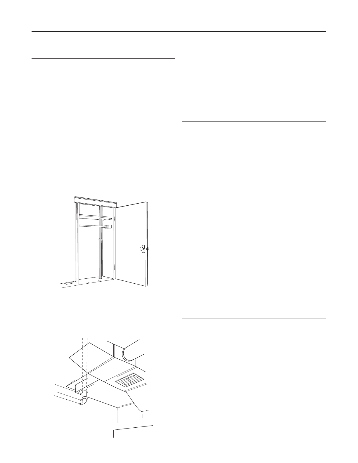
STACKED CLOSETS OR LAUNDRY CHUTE
Many homes will have an upstairs closet located directly
above a downstairs closet. It is easy to run the tubing from
one floor level to another inside these stacked closets. In these
installations the tubing is often left exposed inside the closets.
See figure below. A laundry chute could also provide access
from basement to upper floors. You may also want to consider
running exposed tubing through cabinets or cupboards.
Use the following procedures for installation in existing
construction. Wall inlets in existing construction may be
accessed from below (basement or crawl space) or from above
(attic). Instructions apply to either method.
Starting from farthest wall inlet location, install each inlet as
described below. Working back toward power unit, connect
each inlet line and branch line into main trunk line. See page
24. Complete low voltage wiring as main trunk line is continued
back to power unit. Mount power unit and complete wiring. See
pages 27-29.
AVOIDING IN-WALL OBSTACLES
The tubing which connects the inlet into the trunk line is
threaded through interior partition walls. After you’ve chosen an
inlet location, make sure the wall doesn’t contain some hidden
obstacle which will prevent you from running tubing to the inlet.
ELECTRICAL WIRING
The insulation in these walls will prevent you from running
tubing through them.
EXTERIOR WALLS
Wiring may not obstruct your tubing, but you should always
make sure that tubing does not damage the wiring. Electrical
outlets and wall switches are signs of wiring.
D0019
COLD-AIR RETURN
A cold-air return often provides a straight run from basement
to other levels of the house. See figure below. The ductwork is
easily cut for access. Seal around the tube when completing
the installation.
AD0061
DUCTWORK
Avoid choosing a section of wall that contains ducting. If you
see signs of ductwork—such as floor or ceiling registers—
move your inlet location to another section of the wall.
PLUMBING
Plumbing may or may not prevent you from running tubing
through a wall. If you must choose a plumbing wall for an inlet
location, be extremely careful when making a cutout in the wall.
WALL STUDS
Make sure your location is between wall studs. Locate studs by
tapping walls, looking for electrical outlet (usually fastened to
studs), or noticing finishing nails in the floor molding.
INSTALLING THE INLET TUBING
When your planning is complete, you will have to determine
where all the inlets and the power unit will be located. You have
also mapped out the location of your trunk line and found the
access you need to run vertical tubing from one level of your
house to another level. You should have acquainted yourself
with the methods of joining plastic tubing and acquired the
tools you’ll need to install your NuTone Central Vacuum System.
Now, you can begin installation.
The first step to install the inlet tubing which connects the wall
inlets to the branch lines. As explained before, the inlet lines
run inside interior walls. You will find access to these walls
through your attic or basement. Briefly, you want to find the
exact location in the wall, drill an access hole through the wall
plate or header, and insert the tubing into the wall cavity.
This part of your installation requires close observation and
careful measurements. Take your time and make sure you
accurately line up your access holes with the locations you’ve
chosen for your wall inlets.
12
Page 13
INSTALLATION IN EXISTING CONSTRUCTION (CONT'D)
INSTALLING THE INLET TUBING (CONT'D)
LOCATING ATTIC ACCESS HOLES
Drill the access holes directly above the inlet location. To
accurately locate the access hole, you must find the space
between wall studs where the inlet is to be located. Observe the
area around the inlet location. Look for references you might be
able to find in the attic: electrical wiring, ductwork, doorways,
etc. Measure and note the distance from these references to
the inlet location.
Enter the attic and find the inlet wall. Have a helper downstairs
knock on the top of the wall right above the inlet location; locate
the general area by following the sound. Most likely, you will
have to clear away insulation. Ask your helper to continue
knocking until you locate the area between wall studs directly
above the inlet location.
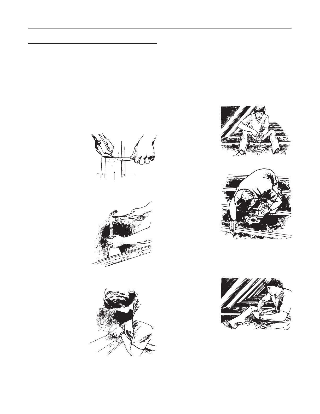
Next, measure the
thickness of the wall. Mark
the exact center of the wall
where you will drill the
access hole. Remember
that the access hole must
be placed exactly in the
center of the wall.
LOCATING BASEMENT ACCESS HOLES
To locate access holes in
the basement, remove the
toe molding or baseboard
at the base of the inlet
wall. Carefully loosen the
molding or baseboard
by inserting the blade of
a putty knife behind it.
Force another putty knife
between the first knife
and the baseboard or
wall. Gently hammer a
cold chisel between the
two knife blades, prying the loosened molding away from the
baseboard or the baseboard away from the wall.
Directly below the inlet
location, drill a 1/16”
reference hole through the
floor into the basement.
(If you’re drilling through
carpet, use an awl to
slightly open the weave.
This will keep the carpet
from wrapping itself around
the drill bit.) Insert a piece
of scrap wire or a clothes
hanger into the reference
hole so you can easily find
the hole in the basement.
Drywall
AR0021A
AR0022
AR0023
Drywall
Wall Plate
Once you’ve found the location in the partition wall, you must
center the access hole in the middle of the wall. Measure half
the thickness of the wall and mark the center of the wall where
you will drill the access hole. If you cannot see the plate, you
can determine this measurement from upstairs. At the nearest
doorway, measure the thickness of the wall, including the
baseboard.
In the basement measure a distance equal to half the thickness
of the wall, using the reference hole as a starting point.
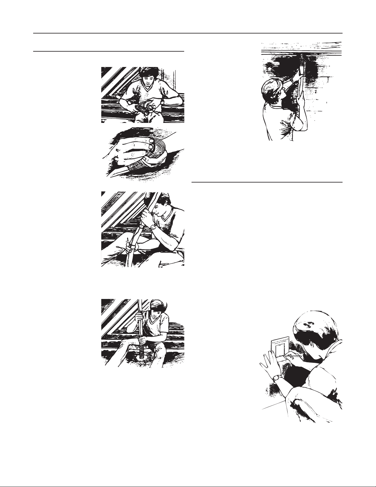
DRILLING THE ACCESS HOLES
Once you are certain that
you’ve located the center
of the wall directly above
the inlet location, use a
2½” hole saw to cut the
access hole through the wall
plate or header and into
the wall cavity. (A 1/2” drill
is recommended.) Remove
the drill from the hole
AR0024
carefully.
Now, use a flashlight to
inspect the wall cavity
through the access hole.
Make sure no hidden
obstacles will interfere
with the tube installation.
(If this inspection reveals
an obstacle, find a new
inlet location.) Repeat this
procedure in your attic
or basement until your
access holes are drilled.
AR0025
ASSEMBLING THE INLET TUBING
Once you’ve drilled the access holes, you assemble the inlet
tubing and insert it into the wall cavity. Refer to “Working With
Plastic Tubing” on pages 5-6 before you begin to assemble the
inlet lines.
Select a section of plastic
tubing and an 8” section
of the flexible inlet tubing.
Apply cement to the
outside of the plastic
tubing and to the inside of
the flexible tubing. Join the
two pieces together and
allow 5 minutes for them
to dry.
AO0013
13
Page 14
INSTALLATION IN EXISTING CONSTRUCTION (CONT'D)
INSTALLING THE INLET TUBING (CONT'D)
ASSEMBLING THE INLET TUBING (CONT'D)
Cut a piece of low voltage
wire which is long enough
for the complete inlet line,
allowing 6” for connections
to the inlet wall plate.
Secure the wire to the
tubing with electrical tape.
AO0014
Tuck the 6” wire lead inside
the flexible tubing so that
it will not snag inside the
wall.
AO0015
If space permits, you
can assemble the entire
inlet line by joining two
sections of tubing with
a stop coupling before
dropping the assembly
into the access hole.
(Remember to only glue
the outside of the tubing
when joining two pieces of
PVC tubing.) Oftentimes,
tight attic spaces require
you to begin your drop and
then join the second section of tubing. Of course, the order of
assembly, and the length of tubing required depend on your
attic space and your wall height.
Whatever the case, insert
the completed inlet line
into the access hole and
thread it down inside the
wall. The inlet line should
be long enough so that it
extends above the joists
in the attic; at this height, it
can be easily connected to
the branch and truck lines.
When cutting the inlet
tubing to length, remember
that your inlet will be placed at 18” above the floor.
AO0016
AO0017
For a basement installation,
assemble the tubing to
the inlet flexible tubing in
the same way and insert
it into the access hole.
A basement inlet line
is necessarily shorter
because it must only reach
18” from the floor to the
inlet. Most of the time,
basement inlet lines are
more easily installed by
two people after the inlet
hole has been cut in the
interior wall. See “Wall Inlet
Installation.”
Complete all your inlet lines, and then proceed to your inlet
installations.
AO0018
WALL INLET INSTALLATION
The wall inlet design allows you to work outside the wall—
where assembly is easy and all the parts you need are
accessible. First, you make a cutout into the wall and locate the
flexible tubing attached to the inlet line which you previously
threaded into the wall. Then, you attach the flexible tubing to
the inlet mounting plate, assemble the other inlet parts, and
make the wiring connections. You place the inlet assembly into
the wall cutout, sandwiching the wall between the inner and
outer parts, and secure the inlet tightly to the wall with two
screws.
Assemble and install the wall inlet as shown in the illustrations
and as explained in the next few pages. Be careful and patient
as you make your first cutout and install your first inlet by
following the procedure step by step—the other inlets will be
easy to install in very little time.
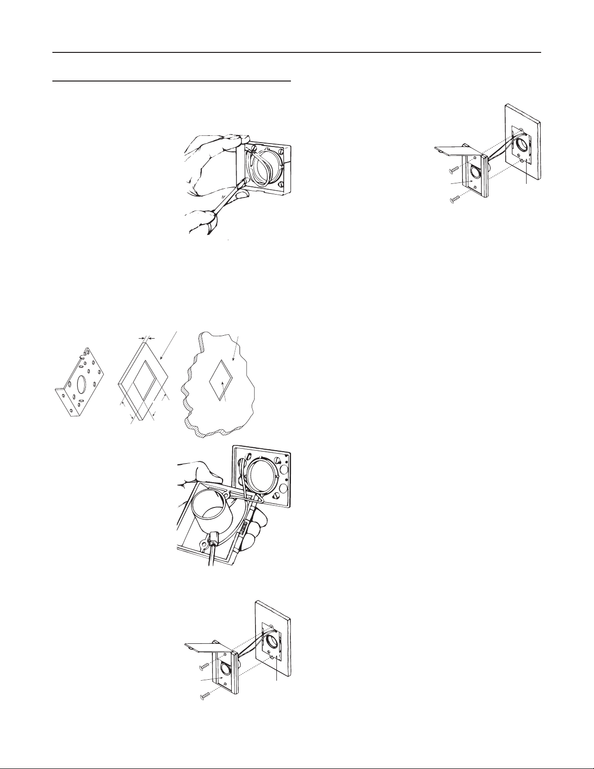
MAKING THE WALL INLET CUTOUT
The wall inlet should be
located 18” on-center from
the floor and directly in line
with the attic or basement
inlet tubing hole you have
already drilled in the wall
plate or header. the wall
inlet cutout must be exactly
3 7⁄8” high by 2 7⁄8” wide. It
is crucial that you make an
accurate cutout, and we
have supplied a template
to help you.
14
Page 15
INSTALLATION IN EXISTING CONSTRUCTION (CONT'D)
e
e
WALL INLET INSTALLATION (CONT'D)
MAKING THE WALL INLET CUTOUT (CONT'D)
Place the template against
the wall so that it is 18”
on-center from the floor.
Use a level along the top
edge of the template to
make sure it is square to
the wall. Mark your wall
for the cutout by tracing
around the inside of the
template. Then use your
pencil to mark the screw
hole locations through
punched holes at the top
and bottom of the template.
Remove the template from
the wall.
AR0027
3/8”
Use an awl or icepick to
punch pilot holes where
you marked the two hole
locations. Now, drill two
3⁄8” diameter holes, using
the pilot holes as the
centers. Locate and drill
these holes exactly as
marked with the template.
Also drill four pilot holes
in the four corners of the
marked area. Make sure
these holes are located
inside the marked line.
Then, using a utility knife,
score along the inside of
the marked line. For plaster
walls, score the plaster
deeply, being careful to
stay inside the marked line.
Next, use a keyhole saw
or a sabersaw to make the
cutout. Again, be extremely
careful to cut along the
inside of the marked line.
CAUTION
When cutting into
plaster walls, make
sure the plaster is firm
and secure around
the cutout area.
AR0028A
AR0032A
AR0033A
DIA.
HOLES
Pilot holes must b
inside marked line
Cut
along
inside
of marked
line
ATTACHING THE INLET MOUNTING PLATE
Reach through the inlet
hole and locate the inlet
tubing. Raise it up inside
the wall until you locate
the inlet tubing. If the inlet
is connected from the
basement, have a helper
insert the inlet tubing into
the access hole until you
can see the flexible tubing.
Then, pull the flexible
tubing through the inlet
hole and remove the low
voltage wiring from inside
the tube. If the end of the flexible tubing is not even, trim it so
that it is exactly even.
Now, remove the nail
flange (used for new
construction) from the inlet
mounting plate. Use pliers
to bend this flange along
the scored lines until you
can break it off.
Apply cement to both the
inside of the flexible tubing
and to the outside of the
mounting plate’s tube ring.
Insert the mounting plate’s
tube ring in the flexible
tubing and twisting the
pieces as you join them
to spread the cement, and
align the mounting plate in
a vertical position.
Hold the assembly in place for a few minutes as the cement
sets; allow 5 minutes for the cement to completely dry.
Now, strip the ends of the two low voltage wires, and then
connect the wires to the screw terminals on the back of the
inlet cover. Make sure the wires are tightly secured under the
terminal screws.
AO0041
15
AO0038
Nail Flang
AO0039A
AO0040
AO0042
Page 16
INSTALLATION IN EXISTING CONSTRUCTION (CONT'D)
WALL INLET INSTALLATION (CONT'D)
ATTACHING THE INLET MOUNTING PLATE (CONT'D)
When the wiring is complete, assemble the inlet cover to the
tube guard and mounting plate. Insert the top screw through
the entire inlet assembly until the screw engages the mounting
plate.
AO0043
COMPLETING INLET ASSEMBLY
Once you have attached the
mounting plate to the flexible
tubing, pull the low voltage wire
through the top wiring hole in
the mounting plate.
AR0034
Insert the bottom screw into
the inlet cover and through the
other parts. Give the screw a
few turns until it firmly engages
in the mounting plate. Now,
level and slightly lower the
assembly. Make sure the wall is
sandwiched between the inner
and outer parts—you’ll be able
to feel if mounting plate is firmly
centered on the inside of the
AO0047
wall.
Hold the inlet in place and
gradually tighten down each
screw a little bit at a time. (If you
completely tighten down one
screw at a time, the mounting
plate may pull away from the
wall at the loose end and slip
back into the cutout.)
AR0035
Complete all your wall inlet installations in this manner. If your
cutouts are accurate, each wall inlet will install more quickly
and easily.
INSTALLING THE INLET
When you place the inlet into
the wall cutout, the mounting
plate and tube guard slip inside
the wall; the inlet cover remains
on the outside.
Holding the inlet assembly
between your thumbs and
fingers, angle the bottom of the
mounting plate into the cutout.
Push the assembly downward
until you have clearance at the
top of the cutout.
Push the top of the mounting
plate into the cutout and lift the
assembly upward until the top
screw seats in the predrilled
hole. At this point, the wall
should be sandwiched between
the mounting plate and the
frame plate.
INLET
AE0024A
AO0044
AO0045
AO0046
MOUNTING
PLATE
360 SERIES INLETS
(CF361 OR CF361F ROUGH-IN)
NOTE: If 330 wall inlet is being used refer to Model 330 Series
Wall Inlet on next page.
B If area is clear, cut an inlet opening in the wall approximately
18" above the floor. Make sure wall opening and 2½" tube
hole line up (see figure below).
31/16 "
29/16 "
21/2"
18"
AD0062
16
Page 17
INSTALLATION IN EXISTING CONSTRUCTION (CONT'D)
e
360 SERIES INLETS
(CF361 OR CF361F ROUGH-IN) (CONT'D)
NOTE: If the wall for mounting the Model 360 inlet is less than
1⁄2", a spacer must be used. See figure below as a
guide.
INLET MOUNTING
BRACKET
SPACER
1/4"
WALL LESS THAN
1
/2" THICK.
F Attach the low voltage wires
to terminal screws on back
of wall inlet (see figure at
right). If using 361 Rough-in
with CI370 Series Inlets,
refer to instructions on page 7,
step D, shown in its figure.
AO0071
21/4"
AD0057A
C Cut a length of tubing that will extend from inlet opening to a
31/4"
PLASTER
GUARD
HOLE
point below floor level (or above ceiling level in attic
installation). Tape low voltage wire to tube and insert tube
through predrilled hole to a level opposite the wall opening.
FLANGED
FITTING
D Apply cement to tube and
install flanged wall fitting.
Make sure fitting is well
seated and sealed (see
LOW
VOLTAGE
WIRING
figure at right).
AD0064A
E Remove plaster frame from mounting bracket. Pull low
voltage wire through hole in bracket and insert bracket into
cutout. Secure bracket to flanged fitting with 4 screws
provided. Be sure seal is secure between flange fitting and
mounting bracket (see figure below).
G Insert wall inlet into bracket
and secure with the two
screws provided (see figure
at right).
AR0047
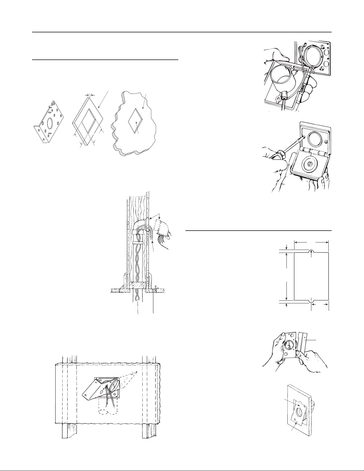
MODEL 330 SERIES
WALL INLET INSTALLATION
(CF329 ROUGH-IN)
1/4"
(6 mm)
7
/8"
B Make cutout according to
dimensions in figure at right.
AD0020A
C Refer to figure at right. Break
off nail plate at scored line.
3
(98 mm)
1/4"
(6 mm)
3
/4"
2
(70 mm)
3/8
" (10 mm) DIA.
3/8
" (10 mm) DIA.
3
/8"
1
(35 mm)
Nail Flang
AD0063
AO0039A
MOUNTING
D Refer to figure at right. Glue
elbow to mounting plate,
PLATE
ELBOW
place assembly into cutout,
and attach elbow to tubing
inside the wall.
MOUNTING
HOLE (2)
AD0021A
17
Page 18
INSTALLATION IN EXISTING CONSTRUCTION (CONT'D)
MODEL 330 SERIES
INLET
EXTENSION
MOUNTING
BRACKET
CUT TO
LENGTH
EXTENSION
SLEEVE
FLOOR
INLET
9
/16"
2
WALL
INLET
WALL INLET INSTALLATION
(CF329 ROUGH-IN) (
E Make sure mounting holes are exactly at top and bottom.
F Connect 2-conductor low voltage wire to terminal screws on
back of wall inlet.
G Refer to figure at right.
Align inlet mounting holes with
mounting plate holes, place
inlet into mounting plate, and
secure with provided screws.
NOTE: If CF382S shorter radius elbow is used, it may be
necessary to use the short mounting screw to avoid
interference with elbow.
CONT'D)
INLET
AE0024A
MOUNTING
PLATE
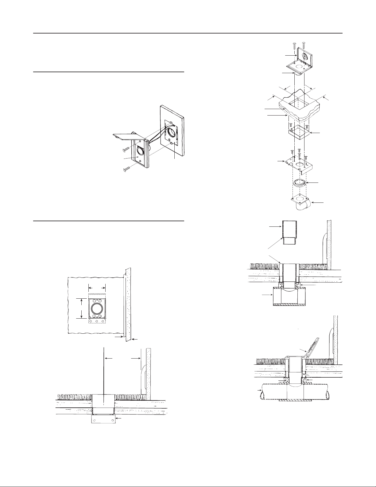
FLOOR INLET INSTALLATION IN
NEW & EXISTING CONSTRUCTION
MODEL 360 SERIES INLETS (361 ROUGH-IN)
B Refer to both figures below. After floor inlet location has been
selected, cut a 3 ¹⁄16" x 2 9⁄16" square hole in floor. Center line
of inlet must be located at least 2½" from wall to allow cover
to be opened when hose is inserted.
TOP VIEW
9
/16"
2
1
3
/16"
AD0067A
SIDE VIEW
AD0068A
C Determine direction of tubing and attach appropriate flanged
MOLDING
21/2" MIN.
APPROX.
fitting to mounting bracket with four (4) screws supplied. Be
sure mounting bracket flange does not interfere with tubing
and seal is securely in place.
WALL
MOUNTING BRACKET
FLANGE
D Refer to figure
at right. Position
bracket with
FLOOR
SUB-FLOOR
frame and flanged
fitting assembly
into cutout from
below and secure
to sub-floor.
AD0069A
E Refer to figure at
right. Large end of
Model 399
extension sleeve
should be cut
to length to allow
proper seating of
inlet against floor
or carpet.
F Refer to figure at
FLANGED
FITTING
AD0070A
right. Pull
low-voltage
2-conductor wire
through mounting
bracket and attach
to terminal screws
on back of floor
inlet. Cement
extension sleeve
to Model 360 inlet.
Insert extension
TUBING
sleeve through
vinyl gasket in
AD0071A
mounting bracket
and firmly seat into flanged fitting.
G For convenience of operation, floor inlet should be installed
to open back toward wall.
H Refer to figure of step D. Secure floor inlet in place with two
screws.
31/16"
FRAME
SEAL
FLANGED
FITTING
MOUNTING
BRACKET
FLANGE
EXTENSION SLEEVE
BRACKETFLANGED FITTING
18
Page 19

CI377W CANSWEEP® UNDER CABINET INSTALLATION
Align the template
®
(cut from this
instruction sheet)
onto the kick plate to
the desired location,
and trace the outline
of the area.
Template
Cut out the desired
opening and
discretely mark the
center of the
opening on the floor.
Mark Center
6¾"
TEMPLATE
CI377W CANSWEEP
2⅜"
If by any chance the opening was cut too big,
a trim plate (part number CI376W) is available
to provide a perfect cover.
Drill a small
reference hole
along the
center line
behind the
kick plate
through the
subfloor.
Locate the
reference hole from
beneath the
subfloor. Cut a
4” x 4” access hole
on your chosen
position along the
center line under
the kick space.
Kick Plate
Opening
Reference
Cabinet Space
Hole
Kick Space
4" x 4" Access
Hole
Trim plate
19
Page 20

CI377W CANSWEEP® UNDER CABINET INSTALLATION (CONT'D)
Fig. A
Fig. B
Solvent weld a coupling
to a piece of 2” central
vacuum pipe, long enough
to reach the 4” x 4” access
hole from the opening on
the kick plate (Fig. A).
Friction fit the other end
of the coupling to the
CanSweep® until secure.
Do not glue, friction fit only
(Fig. B).
Insert the
CanSweep®/pipe
into the opening on
the kick plate.
Use a 90° sweep
elbow fitting to
determine a cut
mark on the other
end of the pipe.
Then cut the pipe
at the mark.
Slide the
low voltage wires
into the
CanSweep® clips
as shown to
complete the wiring
connections.
Slide the
CanSweep®/pipe
and low voltage
wires into the
opening on
the kick plate. Glue
both ends of the
elbow to the piping
system, and then
secure the
CanSweep® to the kick plate with the 2 supplied screws.
Screws
Glue elbow
to pipe
20
Page 21

CI377W CANSWEEP® BASEBOARD WALL INSTALLATION
Do not glue
Choose a desired
position on the baseboard
between two studs.
Place the template (cut
from this instruction sheet)
on the position, and trace
the outline of the area.
Template
Make piping
connections as
required and
ready the short
90° elbow in position
behind the CanSweep®.
Make sure that the opening of the elbow will securely
attach onto the spigot on the back of the CanSweep®
when it is time for connection.
CanSweep® to
the elbow.
Attach wires
Trim the opening on
the baseboard and
through the drywall
until reaching the
2" x 4" bottom wall
plate.
2" x 4" Bottom Plate
Against the edge of the
2" x 4" bottom plate, mark the
center of the opening.
Mark Center
Reference
Reference Hole
Drill a small reference hole
at the mark through the subfloor to below.
Locate the reference hole from below
and measure back 1
to remove the 2"x4" bottom plate
section behind the opening.
7
/8”. Use a 2” hole saw
Hole
2" x 4"
Bottom Plate
1⅞"
Slide the low volt wires into the CanSweep® clips
as shown to complete the wiring connections.
Slide the
CanSweep® and
low voltage wires
into the opening
on the
baseboard.
Friction fit the
CanSweep®
spigot into the elbow. Secure the CanSweep® to the
baseboard with the 2 supplied screws.
21
Page 22

ASSEMBLING THE TUBING SYSTEM
Once you have installed all your inlets, you can complete the
network of tubing that connects your inlets to the power unit.
This network consists of the following parts:
90° Elbows – Used for connecting
the inlet lines to the branch lines. Also
used for making smooth 90° turns in
branch lines or trunk lines.
45° Elbows – Used for a 45° tubing
turn in branch or trunk lines.
90° Tees – Used to connect branch
lines to the trunk lines.
Stop Couplings – Used to join two
lengths of tubing.
Flexible Tubing – Used to bypass
obstacles or to make difficult S-turns
in branch lines. This tubing is not the
same as the inlet flex tube.
BEGINNING THE TRUNK LINE
Start the inlet line which is
farthest from the power unit.
Place 90° elbow onto a section
of tubing and align it with the
inlet tubing at the height it will
run across the attic joists. Mark
the inlet tubing where the elbow
will join, allowing 5/8˝ for the
tubing that inserts into the fitting
collar.
Now, cut the inlet tubing at the
marked line. Make sure the cut
is straight and even. Attach the
elbow and check its fit. Then,
insert the first section of tubing
into the other end of the elbow.
AO0049
AO0050
PVC Tubing – 8’ straight sections
of tubing used for inlet, branch and
trunk lines.
AA0012
Use the tubing and fittings to run branch lines from the inlet
tubing to a main trunk line. Begin at the farthest inlet from the
power unit and work your way toward the power unit. When
you assemble sections with elbows and tees, make sure the
curve in the fitting is aligned so that the air flows toward the
power unit.
Assemble the entire network of tubing and fittings, making
sure every joint is accurately cut and aligned. Then, go back
and cement all the joints. You may run the wiring and make
the wiring connections after the network is assembled and
cemented, or you may make the wiring connections as you
assemble the network. Use the method that best suits your
needs.
AO0051
AO0052
JOINING STRAIGHT LENGTHS OF TUBING
Both branch lines and the trunk lines may require lengths
of tubing longer than those 8´ sections supplied. Use stop
couplings to join two straight lengths of tubing. Insert one end
of the tubing into the stop coupling; join the second length of
tubing into the other end of the stop coupling. Stop couplings
are also used to join long vertical branches which run from one
level to another level of a house.
AO0053
AO0054
22
Page 23

ASSEMBLING THE TUBING SYSTEM (CONT'D)
CONNECTING A BRANCH LINE
A branch line connects the inlet
line to the trunk line. Follow the
methods previously described
for aligning, marking and cutting
the inlet tubing. Attach a 90°
elbow and run tubing from the
inlet line to the trunk line.
AO0055
To align and measure the
branch line, attach a 90° tee
fitting to the trunk line. Make
sure the tee connects with the
air flow going toward the power
unit. Align, measure, and mark
the branch line for inserting it
into the tee fitting. Then, cut
the branch line to length and
insert it into the tee. Check to
make sure the cut is straight
and even. Connect the next
section of tubing to the out-take
side of the tee fitting. Continue
AO0056
Branch Line
Make sure
air flows
toward
Power Unit
the trunk line until you come
to another branch line junction
point.
AO0057A
To Power Unit
CIRCUMVENTING AN OBSTACLE
Wherever possible the branch lines should connect to the trunk
line in straight paths. The fewer turns in a tubing system, the
more efficient air flow. Accordingly, you should locate the inlets
to avoid zig-zags in the branch lines. But, sometimes, when
you just can’t avoid an obstacle, you are required to construct
the tubing around it.
In the example illustrated here, you might run the branch line
at an angle to avoid a chimney. Then, once the branch line
has run past the chimney, you can use a 45° elbow to turn
the branch line back perpendicular to the trunk line. Again, the
branch line and the trunk line connect with a 90° tee.
AO0060
You can also use a piece of flexible tubing to run a branch line
around an obstacle. See “Using Flexible Tubing,” on next page.
COMPLETING THE TRUNK LINE
Continue to run the trunk line toward the power unit, connecting
all branch lines as you go along. Again, make sure you connect
all fittings with the air flow toward the power unit.
Bring the trunk line to the
access hole you have drilled
for the power unit’s intake tube.
Place a 90° elbow over the
hole and cut the trunk line to fit
into this final elbow. Allow 5⁄8˝
of tubing to fit into the elbow’s
collar. Connect the elbow to
the trunk line so that it aligns
over the intake access hole.
You will make the intake tube
connection itself after you have
installed the power unit.
When you are satisfied that all fittings and tubing are aligned for
maximum air flow, make sure that all your cuts are square and
that all joints are tight. Then, prepare the tubing and cement
the joints as described in “Working With Plastic Tubing,” page 5.
AR0037
AO0061
AO0058
AO0059
CONNECTING THE LOW-VO LTAGE WIRING
Ideally, you will run the wiring and make all the wiring
connections after you have completed the tubing system. Of
course, the inlet wiring must be run at the time the inlet tubing
is threaded through the walls.
Run the low voltage wiring along the trunk line; at approximately
12˝-18˝ intervals, use electrical tape to secure the wire to the
tubing. Then, run wiring along the branch lines from the inlet
lines to the trunk line. Also secure this wiring with electrical
tape.
23
Page 24

ASSEMBLING THE TUBING SYSTEM (CONT'D)
CONNECTING THE LOW-VO LTAGE WIRING (CONT'D)
At the joint of the inlet line and the branch line, make a
two-wire connection. Use wire nuts to make the connections
and insulate each connection with electrical tape.
AE0033
At the junction of every branch line and the trunk line, cut the
trunk line wire and connect it to the branch line wire. Connect
this wiring in groups of threes–one branch wire, one in-coming
trunk line wire, and one out-going trunk line wire. Insulate all
wire connections with electrical tape.
Attach the tubing to the joists
or ceiling with either perforated
metal or support strapping
(support strapping is available
from NuTone).
Make all branch line connections in the same way you would
an attic installation. Make sure that all branch lines enter the
trunk line at an angle that is at least levelled with the trunk line.
Make sure all the fittings are oriented so the air flows toward the
power unit. Complete the trunk line to the power unit location.
USING FLEXIBLE TUBING (MODEL CF367)
AR0039
AE0034
Complete all wiring connections up to the power unit’s intake
access hole. You will make this connection when you mount
and connect the power unit. If, for some reason, you want to
connect the wire as you go along, make the same two-wire and
three-wire connections where required.
ASSEMBLING A BASEMENT TRUNK LINE
Basically, the tubing network
is assemble the same way for
a basement installation. Begin
the trunk line at the farthest
inlet line from the power unit.
Measure and cut the inlet tubing
to the length required to align
the trunk line with the joists or
ceiling. Cement the inlet tubing
and connect at 90° elbow. Then,
run the trunk line until you reach
a branch line junction point.
AR0038
Flexible tubing may be used
to circumvent an obstacle or
to make a difficult turn. In the
example illustrated here, the
flexible tubing is used in order
to run a branch line under a
support beam. Attach this tubing
to the PVC tubing, cementing
AO0064
only the outside of the PVC
tubing as you would for a
hard-fitting connection.
Whenever you use the flexible
tubing, you must secure both
ends of it with support strapping.
AO0065
AO0062
AO0063
24
Page 25

POWER UNIT INSTALLATION
CHANGING INTAKE LINE DIRECTION
The intake line connects to the right side of the unit. However,
it is possible to change this configuration; to connect the intake
line to the left side of the unit, follow these steps:
Remove debris pail from power unit by releasing both latches
on sides of the unit, pulling them out and then pushing up.
Detach the pail from unit.
PP5501 ONLY
PP5501 only: Grasp
the edges of the bag
collar and pull down;
the bag will slide off
easily. Do not pull on
the bag. Set the bag
aside.
AO0078
PP5501 only: Using
a Phillips screwdriver
no. 2, remove the
screw tightening the
bag adapter and
intake elbow junction.
Disassemble the
bag adapter from the
intake elbow and set
aside with its screw
and nut.
PP5501 ONLY
AD0075
All units: Disassemble
the intake elbow from
the back of the unit
using a 3/8” socket
to remove its both
retaining nuts and
screws.
AD0076
All units: Flip the
intake elbow 180°,
then reassemble it to
the unit, taking care to
keep its gasket at its
original position.
NOTE: Ensure the
gasket is not folded in
order to prevent lack of suction and noise.
PP5501 only: put the
bag adaptor back in
place to the intake
elbow. Align triangle
with small inclined
stud, then tighten
the junction using
the screw and nut
previously removed in
.
AD0077
PP5501 ONLY
AD0078
PP5501 only: Put the
bag back in place by
grasping the edges of
its collar and insert
over bag adapter. Be
careful not to tear the
bag. Ensure the collar
is positioned between
the taper ring and the
bag stopper on the
bag adapter.
PP5501 ONLY
AO0080
TAPER RING
BAG STOPPER
All units: Put the debris pail back in its place.
CONVERTING POWER UNIT FROM
CYCLONIC OPERATION TO A
BAGGED SYSTEM (DEBRIS BAG
INCLUDED)
Both PP6501 and PP7001 units are factory shipped ready for
use in cyclonic mode, but due to their hybrid design, they can
also be operated with a disposable bag (391). The bag adapter
(included with the unit) must be installed if the disposable bag
will be used. Follow these steps:
NOTE: Do not remove the cyclonic filter.
Remove the pail from unit by releasing its both side latches,
pulling them out and then pushing them up. Detach the pail
from unit.
Assemble the bag
adapter to the intake
elbow. Align triangle
with small inclined
stud.
AD0080
Tighten the junction
using the screw and
nut (included in parts
bag).
AD0081
Unfold the disposable bag and grasp its collar where
indicated. Insert over bag adapter. Be careful not to tear the
bag. Ensure the collar is positioned between the taper ring
and the bag stopper on the bag adapter (see illustration
below). Put the pail back in its place.
TAPER RING
25
AO0085
BAG STOPPER
Page 26

POWER UNIT INSTALLATION (CONT'D)
MOUNTING THE POWER UNIT
Carefully remove debris pail from power unit. Make sure bag
is properly installed in power unit (if need be). Remove the
installation kit and securely reinstall debris pail.
Refer to illustration below to maintain minimum walls and
floor clearance dimensions.
MINIMUM CLEARANCE DIMENSIONS
TOP VIEW
12”
minimum
12” minimum
from ceiling
12”
minimum
FRONT VIEW
C
AD0079A
UPPER
MOUNTING
HOLES
LOWER
MOUNTING
HOLES
L
1” TYP.
18 ¹/
3/4” TYP.
32
8”18 ¹/ 8”
7
/8”
45¼”
MIN.
HEIGHT
Use the provided mounting screws to secure the mounting
bracket on the wall through upper and lower mounting
holes.
Hang power unit onto wall mounting bracket. Ensure
the back brackets of the power unit are engaged with
corresponding wall bracket fingers (or top fingers and lower
tab for PP5501 model; see figure below). Pull the power unit
down to secure
18” minimum
above floor
AD0039A
Position and install the wall mounting bracket with the
provided screws. Refer to illustration at right for proper
mounting dimensions.
CAUTION
Ensure to screw the wall mounting bracket directly
to a wall stud for a solid installation.
PP6501 & PP7001
PP5501
AD0074
26
Page 27

POWER UNIT INSTALLATION (CONT'D)
!
FITTING MAIN LINE TO POWER UNIT
Run house vacuum line up to the elbow behind the power
unit. Insert the end of the line in the elbow opening and
secure house vacuum line by hand tightening the screw
and nut provided (see illustration below). DO NOT GLUE.
INTAKE LINE TYPICAL CONNECTION
TO POWER UNIT
SCREW AND
NUT FROM
PAR TS BAG
INTAKE LINE
AJ0001
NOTE
Ensure to connect the utility valve (included) to the intake
line in the appropriate way, as shown below.
UNIT LOCATION
GROUNDING
INSTRUCTIONS
WARNING
Improper connection of the equipment-grounding
conductor can result in a risk of electric shock.
Check with a qualified electrician or service person
if you are in doubt as to whether the outlet is
properly grounded. Do not modify the plug provided
with the appliance – if it will not fit the outlet, have
a proper outlet installed by a qualified electrician.
Grounding Instructions – This appliance must be grounded.
If it should malfunction or break down, grounding provides a
path of least resistance for electric current, to reduce the risk
of electric shock. This appliance is equipped with a cord having
an equipment-grounding conductor and grounding plug. The
plug must be plugged into an appropriate outlet that is properly
installed and grounded in accordance with all local codes and
ordinances.
WIRING
This appliance is for use on a standard 120 VAC, minimum
dedicated 20-amp branch circuit with a NEMA 5-15R
receptacle. Make sure that the power unit is connected to an
outlet and has a grounding attachment plug that looks like the
plug shown in illustration below. No adapter should be used
with this power unit.
INTAKE LINE INTAKE LINE
AJ0002
Assemble exhaust tubing to exhaust outlet on top or top
side of the unit, according to the power unit model. DO NOT
GLUE.
NOTE FOR PP7001 UNIT ONLY
If desired, the
coupling or elbow
used to connect
the exhaust line to
the top of the unit
may be secured
using two 5/8”
included screws.
See illustration at
right.
AJ0003
NOTE: Using flexible tubing will ease future top cap removal.
Make sure all tubing connections are air tight.
The exhaust should not be vented into a wall, ceiling or
concealed space in the house. It is recommended to vent
the vacuum exhaust air to the outdoors. Exterior vented
exhaust line should end using Model 393 or CI330 wall cap.
NOTE: For optimal indoor air quality, exhausting the power
unit to the outdoors is recommended but is not
required.
CRIMP
CONNECTORS TO
BE CONNECTED
IN LOW VO LTAG E
TABS
GROUNDED OUTLETS
INLET LEADS
MODEL 376-UL
GROUNDING PIN
TO
OTHER
INLETS
AE0044
INLET
NOTE: Inlet leads to be connected to power unit low voltage
tabs using crimp connectors (included in parts bag)
and low voltage harness.
27
INLET INLET
(18/2) LOW VO LTAGE
WIRE
Page 28

FINAL SYSTEM CHECK
Be sure all inlets are closed and soil bag (for PP5501 unit) is in
place. Make sure this bag is properly installed in the power unit
according to directions printed on the bag or in homeowner’s
manual. Check switch on power unit for manual on/off operation.
Check that indicator light on side of power unit is lit.
Remove the owner's manual from the power unit debris pail.
It may be convenient to store it with the cleaning tools and
accessories.
Now it’s time to enjoy the benefits of a NuTone Central
Cleaning System. See Homeowner’s Manual for operating and
care information.
WARRANTY
NUTONE MODELS PP5501, PP6501 AND PP7001
NUTONE
CENTRAL VACUUM POWER UNIT LIMITED WARRANTY
NuTone warrants to the original consumer purchaser that its central vacuum power unit will be free from defects in materials and workmanship
for five (5) years for PP5501 units, eight (8) years for PP6501 units and ten (10) years for PP7001 units. This warranty covers the parts and
labor in an authorized service center for the first three (3) years of the warranty for PP5501 units, the first five (5) years of the warranty for
PP6501 units, the first six (6) years of the warranty for PP7001 units. After these time periods, the parts only will be covered under this warranty.
THERE ARE NO OTHER WARRANTIES, EXPRESSED OR IMPLIED, INCLUDING, BUT NOT LIMITED TO, IMPLIED WARRANTIES OF
MERCHANTABILITY OR FITNESS FOR A PARTICULAR PURPOSE.
During these time periods, NuTone will, at its option, repair or replace the power unit or part without charge, which is found to be defective
under normal use and service. THIS WARRANTY DOES NOT APPLY TO THE INSTALLATION OR THE PARTS USED IN THE INSTALLED
TUBING SYSTEM. All central vacuum hoses, electric or air-driven brushes, filters, attachments and accessories are warranted for one (1) year
from the original purchase date with the exception to consumables such as light bulbs and belts. We invite you to register your product on line
at www.nutone.com/register. NuTone reserves the right to limit this warranty if the product is not registered.
This warranty does not cover (a) normal maintenance and service or (b) any products or parts which have been subject to misuse, negligence,
accident, improper maintenance or repair (other than by NuTone or an authorized representative), faulty installation or installation contrary
to recommended installation instructions.
The duration of any implied warranty is limited to the period as specified for the express warranty.
NUTONE’S OBLIGATION TO REPAIR OR REPLACE, AT NUTONE’S OPTION, SHALL BE THE PURCHASER'S SOLE AND EXCLUSIVE
REMEDY UNDER THIS WARRANTY. NUTONE SHALL NOT BE LIABLE FOR INCIDENTAL, CONSEQUENTIAL OR SPECIAL DAMAGES
ARISING OUT OF OR IN CONNECTION WITH PRODUCT USE OR PERFORMANCE. Please do not return your unit to place of purchase.
Please visit www.nutone.com/register for your closest service center. You may also call 1-888-336-3948 for the name of an authorized
representative in your area. This warranty supersedes all prior warranties.
Warranty service is to be completed by an authorized Service Center designated by NuTone. Where applicable, in home service will be made
available only in areas where a contracted service provider offers service during the first three (3) years of the warranty for PP5501 units,
during the first five (5) years of the warranty for PP6501 units and during the first six (6) years of the warranty for PP7001 units. If in home
service is not available, the product will be repaired or replaced, at NuTone’s discretion, by the nearest authorized service provider. The unit
removal and reinstallation works are under the customer responsibility, and NuTone cannot be charged for them.
To qualify for warranty service, you must notify NuTone at the address or telephone number stated below. We will then forward you the
authorized service depot in your area. You will be required to present evidence of the original purchase date.
Date of Installation Builder or Installer
Model Number and Product Description
IF YOU NEED ASSISTANCE OR SERVICE
For the location of your nearest NuTone Independant Authorized Service Center:
Residents of the contiguous United States, dial toll free: 1-888-336-3948
Please be prepared to provide: Product model number • Date and proof of purchase • The nature of the difficulty
Residents of Alaska or Hawaï should write to: NuTone Inc. Attn: Department of National Field Service, 926 West State Street, Hartford, WI 53027
Product specifications subject to change without notice. Printed in Canada.
28
Page 29

TROUBLESHOOTING GUIDE
PROBLEMS POSSIBLE CAUSES POSSIBLE REMEDY
1. Loss or decrease of
suction occurs.
2. Power unit does
not start, or stops
suddenly.
3. Power unit runs
continuously when
the hose is removed.
• Debris pail or disposable bag is completely full.
• Debris pail gasket damaged or missing.
• Obstruction in the hose. A blockage in the hose
can be determined by inserting the hose into
any wall inlet and, while power unit is running,
check each additional inlet for normal suction
by holding the palm of your hand over the
open inlet. If normal suction is felt at all other
inlets, insert the hose into a second inlet. If the
blockage still exists it is located in the hose.
However, if the blockage does not occur when
the hose is changed, the blockage is probably
located in the tubing system leading to the
original inlet.
• Obstruction in the tubing system inside the
walls.
• Permanent filter or disposable bag torn.
• Wall inlet cover not properly sealed.
• Exhaust tubing or vent clogged.
• Defective inlet. Check other wall inlets.
• Power unit internal circuit breaker has been
activated (the reset button is popped up).
• Blown fuse or tripped circuit breaker on house
electrical panel.
• Defective hose.
• Power unit overcurrent protector has been
activated.
• The unit power switch is in ON position.
• An electrical short has occurred somewhere in
the system.
• Empty debris pail or change the disposable bag
as described in user guide on page 4.
• Replace the debris pail gasket.
• Disconnect the hose from the wall inlet and
insert a blunt instrument into the hose —
slightly smaller in diameter — such as a flexible
garden hose. Push the garden hose through the
cleaning system hose until the obstruction has
been cleared.
• Insert hose end into any inlet to make power unit
running, then place the palm of your hand over
the opposite end of the hose. When you can feel
the suction increase, hold your hand over the
hose end for a few seconds and then quickly
remove your hand. This procedure repeated
several times should clear the obstruction. If the
blockage is not cleared, contact your nearest
Service Center.
• Clean the interior or the unit and install a new
sealed HEPA permanent filter (or disposable
bag); see user guide on pages 4 and 5.
• Check all wall inlet covers to be sure they are
closed and sealed tightly.
• Inspect and remove any blockages.
• Replace defective wall inlet.
• Push on the
circuit breaker
reset button
located on the
left side of the
power unit. If this
button pops up
again, contact
your authorized
Service Center.
• Replace fuse or reset circuit breaker on house
electrical panel.
• Replace hose as required.
• Unplug the power unit, wait at least 15 minutes
and plug back the power unit.
• Set the unit power switch to OFF position.
• Perform a complete check of all wall inlets and
power unit low voltage control lead connections.
Contact your authorized Service Center.
RESET
BUTTON
POWER SWITCH
AC0003
29
Page 30

SERVICE PARTS
PP7001 UNIT
1
2
3
4
PP5501 AND PP6501 UNITS
1
5
4
5
6
16
6
AL0026
15
13
8
7
12
14
9
11
10
17
REPLACEMENT PARTS AND REPAIRS
In order to ensure your unit remains in good working
condition, you must use NuTone genuine replacement
parts only. NuTone genuine replacement parts are specially
designed for each unit and are manufactured to comply
with all the applicable certification standards and maintain
a high standard of safety. Any third party replacement part
used may cause serious damage and drastically reduce the
performance level of your unit, which will result in premature
failing. NuTone also recommends to contact a NuTone
certified service depot for all replacement parts and repairs.
KEY NO.PART NO.DESCRIPTION PP5501 PP6501 PP7001
S10941409 PP7001 TOP CAP ASSEMBLY (INCLUDING ITEM 8) (UPPER PART )1
1
S10941424 PP5501 & PP6501 TOP CAP ASSEMBLY 11
2 S10941416 PP7001 EXHAUST HEPA FILTER 1
3 S10941413 PP7001 TOP CAP ASSEMBLY (INCLUDING ITEM 8) (LOWER PAR T )1
66368 MOTOR WITH UPPER AND LOWER FOAMS AND NUTS 1
4
S10941418 MOTO R WITH UPPER AND LOWER FOAMS AND NUTS 1
S10941419 MOTO R WITH UPPER AND LOWER FOAMS AND NUTS 1
5 S10941420 E
6 S99670649 ROCKER SWITCH 11 1
7 66369 MOTOR FOAM FILTER WITH FASTENER 11 1
8 S10941400 GASKET 11 3
9 S10941415 SEALED HEPA PERMANENT FILTER 11
10 S99670648 DEBRIS PAIL (INCLUDING KEY NO. 11) 1 1 1
11 S10941199 L
12 S10941404 L
13 S10941405 BAG ADAPTER WITH NUT AND SCREW 11 1
14 S10941408 UTILITY VALVE 11 1
15 S10941406 I
16 S99670650 E
17 S30390555 U
* 391 DISPOSABLE BAG (SET OF 3) 1 1 1
* ITEM NOT SHOWN
NOTE: Order service parts by “Part No.” — not by “Key No.”
LECTRONIC BOARD WITH BOTTOM FOAM AND SIDE FOAM 11 1
ATCH AND SCREWS 22 2
ATCH KEEPER WITH SCREWS 22 2
NTAKE ELBOW WITH GASKET, SCREWS, AND NUTS 11 1
XHAUST PORT WITH GASKET AND SCREWS 11
NIT SUPPORT BRACKET 11 1
30
Page 31

GUÍA DE INSTALACIÓN
UNIDADES DE ASPIRACIÓN CENTRAL
SERIE PUREPOWER
PP5501, PP6501 Y PP7001
AB0039
!
ÚNICAMENTE PARA USO RESIDENCIAL
BROAN-NUTONE LLC; HARTFORD, WISCONSIN WWW.NUTONE.COM 1-888-336-3948
R
EGISTRE SU PRODUCTO EN LÍNEA EN: WWW.NUTONE.COM/REGISTER
MODELOS SFDB-DQ, SFDB-DR Y SFDB-DS
!
24010 rev. B
Page 32

IMPORTANTES INSTRUCCIONES DE SEGURIDAD
GUARDE ESTAS INSTRUCCIONES
LEA TODAS LAS INSTRUCCIONES ANTES DE USAR ESTE APARATO.
Cuando use un aparato electrodoméstico, siempre deben tomarse precauciones básicas, incluidas
las siguientes:
ADVERTENCIA
!
Para reducir el riesgo de incendio, choque eléctrico
o lesiones:
1. No se use en superficies húmedas ni en exteriores.
2. No aspire líquidos ni polvos finos (tales como polvo
de tablarroca).
3. No se use para recoger líquidos inflamables o combustibles
tales como gasolina ni se use en áreas donde puedan
estar presentes.
4. No recoja nada que se esté quemando o emitiendo humo,
por ejemplo, cigarrillos, cerillos o cenizas encendidas.
5. No permita que se use como juguete. Ponga mucha
atención cuando se use junto o cerca de los niños.
6. Úsese únicamente como se indica en este manual.
Use únicamente los aditamentos recomendados por
el fabricante.
7. Mantenga el cabello, ropas sueltas, los dedos y todas
las partes del cuerpo alejadas de las aberturas y piezas
en movimiento.
8. Apague todos los controles antes de desenchufar el aparato.
9. Tenga mucho cuidado cuando limpie escaleras.
10. NO maneje el enchufe ni el aparato con las manos húmedas.
11. NO se use con el cable o enchufe dañados. Si el aparato
no está funcionando como debe ser, si ha sufrido caídas,
daños, se ha dejado en exteriores o se ha caído en agua,
lleve el aparato a un Centro de servicio técnico.
12. Mantenga su área de trabajo bien iluminada.
13. Conecte únicamente a un tomacorriente conectado a tierra
correctamente. Consulte las instrucciones de conexión
a tierra mostradas en la página 10.
14. Cuando lleve a cabo la instalación, reparación o limpieza
de la unidad, se recomienda usar gafas y guantes
de seguridad.
PRECAUCIÓN
1. No ponga ningún objeto en las aberturas. No se use con
ninguna abertura bloqueada, manténgase libre de polvo,
pelusa, cabellos y cualquier cosa que pueda reducir el flujo
de aire.
2. Asegúrese de que el aire fluya libremente y escape sin
obstrucciones por la salida superior o lateral.
3. NO se use sin tener el filtro (o filtros, de acuerdo con
el modelo) instalado.
4. NO se use para soplar hojas o basura.
5. NO se coloque ningún objeto encima de la unidad.
6. NO instale la unidad horizontalmente.
7. NO use la bandeja como cubeta de lavar.
8. NO use la bandeja como banquillo.
9. Evite recoger objetos afilados.
10. Este aparato es para usarse en un circuito de derivación
estándar mínimo dedicado de 120 VCA, 20 A.
11. NO desenchufe la unidad jalando por el cable. Para
desenchufar, agarre el enchufe, no el cable.
12. Guarde su aspiradora en interiores en un área limpia
y seca alejada de las temperaturas extremas.
13. Cualquier reparación de servicio distinta a las
recomendadas en este manual debe realizarse
en instalaciones de servicio autorizadas.
14. Recomendamos que su unidad sea revisada por un técnico
especializado una vez al año.
2
Page 33

CONTENIDO
PLANIFICACIÓN Y ARREGLO DEL SISTEMA . . . . . . . . . . . . . . . . . . . . . . . 4-5
LA CASA ESTILO RANCHO . . . . . . . . . . . . . . . . . . . . . . . . . . . . . . . . . . . . . . . . . . . . . . 4
L
A CASA DE DOS PISOS . . . . . . . . . . . . . . . . . . . . . . . . . . . . . . . . . . . . . . . . . . . . . . . 4
LA CASA DE DESNIVELES . . . . . . . . . . . . . . . . . . . . . . . . . . . . . . . . . . . . . . . . . . . . . . 4
UBICACIÓN DE LA UNIDAD DE POTENCIA . . . . . . . . . . . . . . . . . . . . . . . . . . . . . . . . . . . . . . . . 5
LA CASA ESTILO RANCHO . . . . . . . . . . . . . . . . . . . . . . . . . . . . . . . . . . . . . . . . . . . . . . 5
UBICACIONES DE TUBERÍA Y TOMAS DE PARED . . . . . . . . . . . . . . . . . . . . . . . . . . . . . . . . . . . . . 5
GUÍA DE INSTALACIÓN GENERAL . . . . . . . . . . . . . . . . . . . . . . . . . . . . 5-6
LISTA DE HERRAMIENTAS . . . . . . . . . . . . . . . . . . . . . . . . . . . . . . . . . . . . . . . . . . . . . . 5
TRABAJANDO CON TUBERÍA DE PLÁSTICO . . . . . . . . . . . . . . . . . . . . . . . . . . . . . . . . . . . . . . 5-6
INSTALACIÓN EN UNA CONSTRUCCIÓN NUEVA . . . . . . . . . . . . . . . . . . . . 7-10
INSTALACIÓN OCULTA DE TOMA DE PARED . . . . . . . . . . . . . . . . . . . . . . . . . . . . . . . . . . . . . . . 7
INSTALACIÓN DE LA TUBERÍA . . . . . . . . . . . . . . . . . . . . . . . . . . . . . . . . . . . . . . . . . . . . . 8
INSTALACIÓN DE TOMA DE PARED . . . . . . . . . . . . . . . . . . . . . . . . . . . . . . . . . . . . . . . . . . . 9
CI399 ELECTRAVALVE™ INSTALACIÓN DE TOMA ELECTRIFICADA (INSTALACIÓN OCULTA DE CI399RK) . . . . . . . . . . . . 10
CI1358 SUPERVALVE™ JUEGO DE INSTALACIÓN OCULTA Y TOMA DE PARED. . . . . 11
INSTALACIÓN EN UNA CONSTRUCCIÓN EXISTENTE . . . . . . . . . . . . . . . . . 12-18
UBICANDO LOS PUNTOS DE ACCESO EN LA CONSTRUCCIÓN EXISTENTE . . . . . . . . . . . . . . . . . . . . . . . . . . 12
RODEAR OBSTÁCULOS EN EL INTERIOR DE LAS PAREDES. . . . . . . . . . . . . . . . . . . . . . . . . . . . . . . . . 12
INSTALACIÓN DE LA TUBERÍA DE TOMA. . . . . . . . . . . . . . . . . . . . . . . . . . . . . . . . . . . . . . . 12-14
INSTALACIÓN DE TOMA DE PARED . . . . . . . . . . . . . . . . . . . . . . . . . . . . . . . . . . . . . . . . . 14-16
TOMAS SERIE C370 O 360 (INSTALACIÓN OCULTA DE CF361 O CF361F) . . . . . . . . . . . . . . . . . . . . . 16-17
INSTALACIÓN DE TOMA DE PARED MODELO SERIE 330 (INSTALACIÓN OCULTA CF329) . . . . . . . . . . . . . . . . . 17-18
INSTALACIÓN DE TOMA DE PISO EN CONSTRUCCIÓN NUEVA Y EXISTENTE . . . . . . . . . . . . . . . . . . . . . . . . . . 18
CI377W CANSWEEP® INSTALACIÓN DEBAJO DEL GABINETE . . . . . . . . . . . . 19-20
CI377W CANSWEEP® INSTALACIÓN EN LA PARED CON ZÓCALO . . . . . . . . . . . . 21
ENSAMBLE DEL SISTEMA DE TUBERÍA . . . . . . . . . . . . . . . . . . . . . . . . 22-24
INSTALACIÓN DE LA UNIDAD DE POTENCIA . . . . . . . . . . . . . . . . . . . . . 25-27
CAMBIO DE DIRECCIÓN DE LA LÍNEA DE ENTRADA. . . . . . . . . . . . . . . . . . . . . . . . . . . . . . . . . . . . 25
CONVERSIÓN DE LA UNIDAD DE POTENCIA DE OPERACIÓN CICLÓNICA A UN SISTEMA EMBOLSADO (BOLSA DE DESECHOS INCLUIDA) 25
MONTAJE DE LA UNIDAD DE POTENCIA . . . . . . . . . . . . . . . . . . . . . . . . . . . . . . . . . . . . . . . . 26
CONECTANDO LA LÍNEA PRINCIPAL A LA UNIDAD DE POTENCIA . . . . . . . . . . . . . . . . . . . . . . . . . . . . . . 27
INSTRUCCIONES DE CONEXIÓN A TIERRA . . . . . . . . . . . . . . . . . . . . . . . . 27
CABLEADO . . . . . . . . . . . . . . . . . . . . . . . . . . . . . . . . . . . . . . . . . . . . . . . . . . . . 27
REVISIÓN FINAL DEL SISTEMA . . . . . . . . . . . . . . . . . . . . . . . . . . . . . . . 28
GARANTÍA. . . . . . . . . . . . . . . . . . . . . . . . . . . . . . . . . . . . . . . . . . . 28
GUÍA DE LOCALIZACIÓN Y SOLUCIÓN DE PROBLEMAS . . . . . . . . . . . . . . . . . 29
PIEZAS DE SERVICIO. . . . . . . . . . . . . . . . . . . . . . . . . . . . . . . . . . . . . 30
3
Page 34

PLANIFICACIÓN Y ARREGLO DEL SISTEMA
El sistema de limpieza central NuTone consta de una unidad de potencia, tubería y conectores de PVC, tomas de pared, una
manguera flexible y varios aditamentos de limpieza.
La unidad de potencia está diseñada para montarse en pared alejada del área de convivencia de la casa y conectada al área de
convivencia por medio de tubería, conectores y tomas instaladas ocultas en la pared permanentemente.
Generalmente, una instalación requiere de 3 a 4 tomas y 16 a 20 pies de tubería por cada toma. Se sugiere que se utilice un plano
de piso para determinar con mayor exactitud la cantidad de materiales necesarios.
Use los siguientes ejemplos como ayuda en la planificación de la instalación en construcciones nuevas o existentes. Debe poder
adaptar los ejemplos mostrados al arreglo específico a su casa.
LA CASA ESTILO RANCHO
Aquí la unidad de potencia está montada
en la cochera. La tubería de entrada
y de salida, la única tubería expuesta en
la instalación, se tiende hacia arriba por
la pared de la cochera y hacia el ático. La
SALIDA
línea troncal se tiende horizontalmente
a través del ático desde la unidad de
potencia hasta la ubicación de toma más
lejana. Las líneas derivadas se esparcen
a lo largo del ático, conectando la línea
troncal a la tubería de toma. Cada tubo
de toma está ensartado verticalmente
a través de una pared interior. Localizadas
en pasillos y en habitaciones grandes,
las tomas se colocan para proporcionar
máximo acceso a todas las áreas
de limpieza. Ver la figura de la derecha.
UNIDAD
DE POTENCIA
AH0003E
ENTRADA
LA CASA DE DOS PISOS
En una casa de dos pisos se utiliza comúnmente un sistema
de doble línea troncal. En la instalación mostrada en la
imagen de la derecha, la unidad de potencia está montada
en el sótano. La tubería de entrada se tiende hacia arriba por
la pared del sótano y se conecta con la línea troncal principal,
la cual se tiende a lo largo del cielo del sótano no acabado.
Dos tomas en el primer piso están conectadas a la línea
troncal del sótano por medio de líneas de toma vertical que
se tienden a través de las paredes exteriores. En el centro
de la casa, una línea derivada vertical se tiende desde la
línea troncal del sótano, a través de closets apilados, hacia
arriba al ático. Una segunda línea troncal se tiende a través
del ático y dos líneas derivadas se conectan a las líneas de
toma las cuales bajan a través de las paredes interiores del
piso de arriba. Ver la figura de la derecha.
LA CASA DE DESNIVELES
LÍNEA TRONCAL
UNIDAD DE
POTENCIA
AH0005E
LÍNEA
DERIVADA
VERTICAL
ENTRADA
LÍNEA DERIVADA
TOMA
LÍNEA TRONCAL
DEL ÁTICO
SALIDA
LÍNEA TRONCAL
DE SÓTANO
LÍNEA
DE TOMA
LÍNEA DE
TOMA
TOMA
Al igual que la casa de dos pisos, la
instalación en desniveles comúnmente
requiere de una línea troncal de dos
niveles. Aquí, la unidad de potencia está
ubicada en la cochera. La tubería de
entrada se tiende expuesta hacia arriba
por la pared de la cochera y hacia el ático
a nivel del suelo. Dos líneas derivadas
conectan esta parte de la línea troncal a
las líneas de toma las cuales bajan por
dentro de las paredes interiores. Una línea
derivada vertical se tiende hacia el ático
del piso de arriba, donde la línea troncal
se deriva en forma T. Esta línea troncal se
conecta a dos líneas de toma en el piso de
arriba y a una línea de toma la cual baja
por una pared del piso de arriba hacia la
habitación de servicio de tercer nivel para
dar servicio a todo este piso. Ver la figura
de la derecha.
AH0004E
SALIDA
ENTRADA
UNIDAD
DE POTENCIA
4
DERIVADA
VERTICAL
LÍNEA
TRONCAL
LÍNEA
LÍNEA
DERIVADA
TOMA
LÍNEA
DERIVADA
LÍNEA DE
TOMA
TOMA
Page 35

PLANIFICACIÓN Y ARREGLO DEL SISTEMA (CONT.)
!
!
ADVERTENCIA
No instale en exteriores. Cuando lleve a cabo la
instalación, el mantenimiento o la limpieza de la unidad,
se recomienda usar gafas y guantes de seguridad.
UBICACIÓN DE LA UNIDAD
DE POTENCIA
• Ubique la unidad de potencia desde el área de convivencia
general en un lugar accesible para limpieza y mantenimiento.
• Cuando planifique la instalación de la unidad de potencia
PP7001, recuerde que está equipada con una toma para
dar servicio a la cochera, sótano, cuarto de servicio, etc.,
donde quiera que esté ubicada.
• Ubique la unidad de potencia dentro de 6 pies de distancia
de un tomacorriente eléctrico conectado a tierra. La unidad
de potencia requiere una fuente de alimentación de 120 VCA.
• No coloque la unidad de potencia cerca de una fuente de
calor extremo (por ejemplo.: calentador de agua) o en un
área con alta temperatura ambiente (por ejemplo.: ático,
cuarto de calefacción).
• Si la unidad de potencia se ubica en un clóset o en un
pequeño cuarto de servicio, asegúrese de que el área esté
bien ventilada (por ejemplo.: con rejillas en las puertas).
• Para un óptimo rendimiento, se recomienda un dispositivo
extractor hacia el exterior para la unidad de potencia. El
extractor no debe ventilar hacia una pared, cielo o espacio
cerrado en la casa. La línea del extractor debe ventilar hacia
el exterior de la casa usando cornisas de pared modelo 393
o CI330.
UBICACIONES DE TUBERÍA Y TOMAS
DE PARED
Ubique las tomas en las paredes interiores, eligiendo
las ubicaciones centrales que permitan limpiar varias
habitaciones desde una sola toma usando una manguera
de 30 pies de largo.
La instalación de tubería debe consistir de una línea troncal
principal que se tiende desde la toma de pared más lejana
hasta la ubicación de la unidad de potencia, con líneas
derivadas tendidas hacia cada toma adicional. Mantenga
todas las líneas de tubería lo más rectas posibles y use la
menor cantidad posible de conectores.
Comenzando en el área más alejada de la unidad de
potencia, elija una ubicación de toma tentativa. Mida 30 pies
desde la ubicación de toma propuesta hasta la esquina más
lejana de las habitaciones que se van a limpiar por esa toma,
para determinar si la ubicación de la toma es adecuada. Si
está trabajando con planos (o planos del edificio dibujados
a una escala de 1⁄4" = 1 pie), use una cadena de 7½" como
guía para determinar las ubicaciones de las tomas.
Ubique las tomas dentro de seis pies de un tomacorriente
eléctrico para permitir el uso de una manguera
eléctrica opcional.
Asegúrese de que las tomas no sean bloqueadas por
puertas o muebles.
Asegúrese de que las tomas no interfieran con las instalaciones
eléctricas, plomería y otras instalaciones mecánicas.
Mueva la ubicación tentativa de la toma como sea
necesario. Siga el mismo procedimiento para determinar
cada ubicación de toma adicional, siempre trabajando hacia
la unidad de potencia.
GUÍA DE INSTALACIÓN GENERAL
ADVERTENCIA
Cuando las regulaciones locales aplicables requieran una instalación más estricta y/o cumplir con
requerimientos de certificación, los requerimientos antes mencionados reemplazarán a los de este
documento y el instalador acepta cumplir con estos requerimientos bajo su propio riesgo.
LISTA DE HERRAMIENTAS
Dependiendo de su instalación, puede requerir el uso de estas herramientas. Se recomienda usar herramientas eléctricas
o neumáticas para realizar su instalación rápidamente. También, use una máscara de protección cuando corte conductos (polvo
PVC) y guantes cuando use pegamento.
• Pelacables • Talado de 1/4" • Nivel • Linterna
• Navaja de servicio • Espátula • Broca para taladro • Cinta aislante eléctrica
• Navaja • Martillo • Desarmador • Gafas de seguridad
• Sierra perforadora 2½" • Sierra de calar • Llave • Segueta
• Taladro de 1/2" • Cincel corta frío • Cinta de medir
TRABAJANDO CON TUBERÍA
DE PLÁSTICO
RECORTE DE TUBERÍA
Antes de cortar un tramo de tubería,
mida con exactitud el largo que
necesita. Deje 5/8” de tubo para
insertar en los conectores y 1½” para
insertar en la tubería flexible. Corte la
tubería de plástico con una segueta,
asegurándose de que el corte sea
exactamente cuadrado. (Puede usar
un cortador de tubo si está disponible).
Use cortadoras de cable o tijeras de
hojalatero para cortar la tubería flexible.
Los tramos de 8” de tubería flexible
suministrados con cada toma no deben
cortarse. Ver la figura de la derecha.
AR0016
Use una navaja pequeña para quitar
cualquier rebaba del interior del
tubo. También puede usar lana de
acero para eliminar las rebabas. Las
rebabas deben eliminarse ya que
pueden obstruir el flujo de aire o formar
taponamientos al enmarañar cabellos
e hilos de alfombras. Ver la figura de la
derecha.
AR0017
5
Page 36

GUÍA DE INSTALACIÓN GENERAL (CONT.)
TRABAJANDO CON
TUBERÍA DE PLÁSTICO (CONT.)
RECORTE DE TUBERÍA (CONT.)
A continuación, use una lima para
biselar ligeramente el exterior del tubo
de modo que se deslice fácilmente en
el conector. Use lana de acero o papel
de lija ligera para pulir la superficie
del tubo que se va a pegar. De este
modo limpia el tubo y asegura un buen
sellado. Ver la figura de la derecha.
HACER UNA UNIÓN
Inserte el tubo en el conector,
alineando las dos piezas que
se van a instalar. Marque el
tubo y el conector de modo que
pueda realinear rápidamente
la unión. Ver la figura de
la derecha.
Aplique pegamento
únicamente al exterior del
tubo. Unte el pegamento
generosamente en una tira
de una pulgada de ancho.
Inserte el tubo en el conector
con las marcas de alineación
separadas un cuarto de vuelta,
y luego empuje rápidamente
y gire el conector hacia
las marcas de alineación
esparciendo el pegamento.
Deje secar la unión durante un
minuto. También puede usar
cinta de aislamiento eléctrica o
cinta adhesiva para conductos
para sellar aún más la unión.
Ver la figura de la derecha.
AR0018
AR0019
AO0010
PEGAR LA TUBERÍA FLEXIBLE
Asegúrese de que los extremos de la tubería flexible estén
parejos, recorte como sea necesario. Cuando una la tubería
flexible con la tubería de plástico o con una placa de montaje
de toma, aplique el pegamento a ambos lado interior de la
tubería flexible y lado exterior de la tubería de plástico o anillo
de tubería de la placa de montaje. Gire las dos piezas mientras
las une para extender uniformemente el pegamento. Deje
reposar el pegamento durante cinco minutos en la tubería
flexible. También puede usar cinta de aislamiento eléctrica
o cinta adhesiva para conductos para sellar aún más la unión.
SUJETAR EL CABLE A LA TUBERÍA
El cable de bajo voltaje
se tiende a lo largo de la
tubería. Para asegurar que el
cable se sujete y no cuelgue
en una pared, use cinta
eléctrica para adherir el cable
a la tubería. Aplique cinta al
cable cada 12 a 18 pulgadas
aproximadamente. Ver la figura
de la derecha.
AO0011
6
Page 37

INSTALACIÓN EN UNA CONSTRUCCIÓN NUEVA
INSTALACIÓN OCULTA DE TOMA DE PARED
Una vez que las ubicaciones para las tomas de pared se han determinado, monte todos los soportes de toma.
Elija el soporte de montaje apropiado para la toma que va a instalar. (Consulte la gráfica a continuación).
SERIE DE INSTALACIÓN OCULTA
395 396-3 CI3301RK CI3303RK CF329 CF361 CF361F CI399RK
330 X X X
360XX XX
VÁLVULA
SERIE DE
Para ubicar un soporte en un montante de pared, mida aproximadamente 18" hacia arriba desde el nivel del piso acabado.
(La altura puede variar conforme a preferencia individual)
CI358 Instalación oculta y válvula de pared vendidas juntas
DE PARED
CI399 X
MODELOS CF361 Y CF361F
(PARA USARSE CON TOMA 360)
Consulte la figura a continuación. Clave el soporte en el
lado del montante de modo que el borde frontal del soporte
quede al ras con el frente del montante. (El soporte también
puede clavarse al borde frontal del montante). Ver imagen
del montaje de cara. Para el montaje de cara, use las orejas
guías en el soporte para una alineación correcta).
MODEL CF361 & CF361F
MONTAJE
LATERAL
23/8"
AD0059E
MONTAJE
FRONTAL
13
/16"
1
MODELOS CF329 (PAR A USARSE CON TOMAS 330)
Cuando use el Modelo CF329, pegue
el codo a la placa de montaje. Fije
al montante como se muestra en la figura
de la derecha.
AD0015
Consulte la figura a continuación. Quite el cartón del
marco protector de yeso. Usando los cuatro (4) tornillos
suministrados, fije el conector bridado y el sello de la toma
a la parte posterior de la toma.
Reinstale el cartón en el marco protector de yeso
AD0060
7
Page 38

INSTALACIÓN EN UNA CONSTRUCCIÓN NUEVA (CONT.)
!
INSTALACIÓN DE LA TUBERÍA
Siga los siguientes lineamientos de instalación cuando instale
la tubería.
B Comience la instalación de la tubería en la toma más lejana
y trabaje hacia la unidad de potencia.
C La tubería tendida hacia la unidad de potencia debe ser lo
más recta posible.
D Cuando ensamble las secciones con codos y conectores T,
asegúrese de que la curva en los conectores esté alineada
de modo que el aire fluya hacia la unidad de potencia.
E Las líneas derivadas siempre deben unirse a la línea troncal
desde arriba o al mismo nivel. Nunca haga la unión de una
línea derivada desde un ángulo debajo de la línea troncal.
F Consulte la figura de la
derecha. Encamine el el
cable de bajo voltaje (Modelo
376UL) y sujételo a la tubería
cuando esté instalando la
tubería. El soporte de tubo del
Modelo CF380 se puede usar
para soportar largos tramos
de tubería (posicione cerca
de las vigas) y para sujetar el
cable a lo largo de la tubería.
Sujete la tubería a las vigas
o montantes. Deje un tramo de
AE0040
6" de cable aproximadamente
para conectarse a cada toma.
G Recorte un orificio con un diámetro de 2½" en la solera,
cabezal o montante directamente en línea con la
abertura del conector del soporte de la toma. Ver la figura
a continuación para las dimensiones de la línea central.
MONTAJE DE MODELO CF361
2½” DIÁMETRO DE AGUJERO
3
2
MONTAJE LATERAL
A TRAVÉS DE SOLERA
”
/8
13
”
1
/16
MONTAJE DE MODELO CF329
2”
13
”
1
/16
13
”
1
/16
MONTAJE FRONTAL
2½” DIÁMETRO DE AGUJERO
A TRAVÉS DE SOLERA
I Consulte la figura de la derecha.
Recorte la tubería, manteniendo el
corte cuadrado.
AR0016
J Consulte la figura de la derecha.
Elimine las rebabas del interior
y exterior de la tubería.
K Antes de aplicar el pegamento,
AR0017
ensamble la sección al conector
de la toma, revise que sea de
longitud correcta.
L Consulte la figura de la derecha.
Aplique pegamento para PVC
(Modelo 379) al exterior de la
tubería. Aplique una capa a la
tubería de 1" aproximadamente
hacia atrás. Tenga cuidado de evitar
que el pegamento ingrese al tubo.
M Consulte la figura de la derecha.
AR0020
Inserte el tubo en el conector con un
movimiento giratorio para esparcir
uniformemente el pegamento.
Asegúrese de que la tubería asiente
firmemente en el conector.
AO0012
N Si los conectores se fijaron a la tubería en el extremo
opuesto del soporte de toma, asegúrese de que la
alineación sea correcta antes
de que el pegamento se seque.
13
”
1
/16
AD0055E
H Ver la figura a continuación. Mida la longitud de la tubería
MONTAJE FRONTAL
necesaria para conectar la toma a la línea troncal. Deje 3⁄4" de
tubería aproximadamente para insertarse en los conectores.
INCLUIR EL RECESO DEL
3/4”
(19 mm)
CONECTOR
AD0017E
CONECTOR EN LA MEDICIÓN
TUBERÍA MEDICIÓN
TUBERÍA DE PVC
3/4”
(19 mm)
CONECTOR
O Consulte la figura de la derecha.
Encinte el cable a la tubería para
sujetarlo en su lugar y luego inserte
a través del orificio en el soporte de
la toma.
AD0018
P Conecte cada línea de toma y línea derivada a la línea troncal
principal. Instale el cableado de bajo voltaje mientras la línea
troncal principal continúa de regreso a la unidad de potencia.
ADVERTENCIA
Cuando la tubería se tiende a través del montante
de pared, solera, cabezales o en cualquier lugar del
edificio donde los materiales de construcción se van
a fijar, coloque una placa para clavos (Modelo 378)
sobre el área (en ambos lados si es necesario) para
prevenir que los clavos perforen la tubería.
8
Page 39

INSTALACIÓN EN UNA CONSTRUCCIÓN NUEVA (CONT.)
INSTALACIÓN DE LA TOMA DE PARED
TOMA DE PARED MODELO 360
INSTALACIONES OCULTAS CF361 Y CF361F)
(
B Quite el protector de yeso de cartón.
C Consulte la figura de la
derecha. Para algunas
construcciones paneles de
yeso o tablarroca, el marco
protector de yeso se extenderá
más allá de la pared acabada.
En este caso, quite el marco
de yeso del soporte de
montaje quitando los tornillos
de montaje.
NOTA: Cuando use el soporte de toma modelo CF361
y CF361F en paredes más delgadas que 1⁄2", use un
espaciador de 1⁄4" (no suministrado) entre la pared
y el soporte de toma. Ver figura a continuación. El
espaciador puede estar hecho de madera laminada,
Masonite™, etc. Se puede usar pegamento de
contacto para sujetar el espaciador en su lugar durante
el ensamble. La configuración del espaciador puede
variar dependiendo de la instalación.
SOPORTE DE
MONTAJE DE
TOMA
ESPACIADOR
1/4"
AR0045
PARED MENOR QUE
1
/2" DE ESPESOR.
TOMA DE PARED MODELO 330 (INSTALACIÓN
OCULTA CF329)
B Consulte la figura de la derecha.
Conecte un cable de bajo
voltaje de 2 conductores a los
tornillos de terminal en la parte
posterior de la toma de pared.
C Alinee los orificios de montaje
de la toma con los orificios
en la placa de montaje.
D Consulte la figura de la
derecha. Coloque la toma en
la placa de montaje y fije con
los dos tornillos suministrados.
TOMA
AE0024E
PLACA DE
MONTAJE
21/4"
AD0057E
D Consulte la figura de la
31/4"
AGUJERO DE
PROTECTOR
DE YESO
derecha. Conecte el cable
de bajo voltajede dos
conductores a los tornillos de
terminal en la parte posterior
de la toma de pared.
AE0040
E Guíe el exceso de cable de regreso a través del orificio en
el soporte de la toma y el conector bridado.
F Consulte la figura de la
derecha. Coloque la toma en
el soporte de montaje y fije.
TOMA
AE0024E
PLACA DE
MONTAJE
9
Page 40

INSTALACIÓN EN UNA CONSTRUCCIÓN NUEVA (CONT.)
!
CI399 ELECTRAVALVE™
INSTALACIÓN DE TOMA
ELECTRIFICADA (INSTALACIÓN
OCULTA CI395RK)
B
C
B Sujete la placa de montaje en un travesaño. Ubique el
orificio inferior de la placa de montaje que se identica como
“Wire Trap” (soporte del cable) y utilice un sujetacables
de plástico para sujetar el cable en la parte posterior de
la placa de montaje, en el sitio donde está la marca de
25,4cm (10pulg.).
C Coloque el enchufe ensamblado con el cable a través del
orificio superior de la placa de montaje. Sujete el enchufe
con la lengüeta de la placa de montaje como se muestra.
Con esto se mantendrá fijo y no se dañará durante la
colocación de la lámina de yeso y las tareas de acabado.
D Lleve el cable hasta la caja de conexión adyacente. Si ha
de pasar por un travesaño, perfore un orificio directamente
en el centro de este último y pase el cable a través de él.
Pele 15 cm (6 pulg.) del revestimiento exterior de ese
extremo del cable y colóquelo en el interior de la caja
de conexión a través de un dispositivo de protección
contra tirones. Asegúrese de que dicho dispositivo quede
colocado contra el revestimiento exterior (no lo apriete
demasiado). Deje 13 mm (1/2 pulg.) de revestimiento dentro
de la caja de conexión. Doble los 15 cm (6 pulg.) de cable
negro y cable blanco en el interior de la caja de conexión.
Deje los cables para que el electricista los conecte cuando
instale la toma.
E Cuando se haya colocado el yeso y se hayan realizado las
tareas de acabado; tire del enchufe para que se suelte de
la lengüeta e insértelo a presión en la abertura situada en
la parte posterior de la nueva ElectraValve®. Asegúrese de
que el enchufe quede firmemente bloqueado en su sitio
como se muestra. Conecte los cables de bajo voltaje en los
tornillos de contacto.
F Inserte la válvula en la placa de montaje y sujétela a esta
PRECAUCIÓN
El uso de herramientas de potencia tal como los
buriladores no se recomienda para usarse con la
instalación de la toma, ya que la remoción de la pared
de yeso con estos dispositivos puede causar daños
a la placa de montaje y/o al enchufe de la toma.
Lengüeta
Soporte
del cable
D
E
F
Cables de bajo voltaje
13 mm
(1/2 pulg.) de
revestimiento
exterior
Lengüetas
de bloquero
de la
válvula
con los tornillos que se suministran.
ADVERTENCIA
Todas las válvulas de conexión directa del lugar
y de la instalación deben conformar con todos los
códigos de construcción locales y municipales.
AE0050E
10
Page 41

C1358 SUPERVALVE™ JUEGO DE INSTALACIÓN OCULTA
!
Y TOMA DE PARED
VÁLVULA DE PARED DEL SISTEMA DE LIMPIEZA DE ASPIRACIÓN
AL0008E
CENTRAL- TIPO A
INSTRUCCIONES DE SEGURIDAD
ÚNICAMENTE PARA USO RESIDENCIAL. INSTALE ÚNICAMENTE EN UNA ALIMENTACIÓN
NOMINAL DE 120 V, 60 Hz, 7 A PROTEGIDA CON UN DISPOSITIVO PROTECTOR DE
SOBRECORRIENTE MÁXIMA DE 15 A.
EL CONECTOR DE CLAVIJA EN ESTE TIPO DE VÁLVULA DE PARED ESTÁ DESTINADO
PARA USARSE EN UNA ALIMENTACIÓN NOMINAL DE 120 V, 60 Hz, 7 A ÚNICAMENTE.
SE REQUIERE QUE SEA CABLEADO POR UN ELECTRICISTA CALIFICADO Y QUE
CONFORME CON LOS CÓDIGOS ELÉCTRICOS LOCALES.
ADVERTENCIA
¡NO operar en superficies húmedas!
CONSTRUCCIÓN NUEVA
Instale los CONDUCTORES DE CABLEADO DEL EDIFICIO (1) a través del tipo de CONECTOR (2) eléctrico aprobado
B
(suministrado) hasta que sobresalga aproximadamente seis pulgadas del conector. Asiente el conector firmemente en la
abertura en el COMPARTIMIENTO DE CABLEADO (4).Inserte y asegure la LENÜETA DE BLOQUEO (3).
C Empalme los cables del TOMACORRIENTE DE VÁLVULA DE TOMA (7) a los conductores de cable del edificio protuberantes
con los CONECTORES DE CABLE DE ROSCA Número 31 (8) (no suministrados).
NOTA: Cable BLANCO a cable BLANCO y cable NEGRO a cable NEGRO.
D Encamine los CABLES DEL RELÉ DE BAJO VOLTAJE (5) a través de la abertura en la TAPA LVT (6) y conecte a los dos
tornillos de contacto de la TAPA DE VÁLVULA DE TOMA (9).
E Empuje la tapa de la válvula de toma (10) en la PLACA DE MONTAJE (11 ). Al mismo tiempo, empuje los CONDUCTORES
ELÉCTRICOS (12) y los conectores (8) al COMPARTIMIENTO DE CABLEADO (4). Retroceda los dos tornillos que sujetan
el compartimiento en su lugar. Deslice debajo del SUJETADOR DE PARED ACABADA (13) debajo de los tornillos/cabezas y
apriete firmemente ambos el compartimiento de cableado y el sujetador superior de pared acabada (13) con los TORNILLOS
DE MONTAJE (suministrados).
F Instale el SUJETADOR INFERIOR DE PARED ACABADA (14) con los tornillos (suministrados).
G Fije la tapa de válvula de toma (10) a la placa de montaje (11) usando los dos TORNILLOS (15) de igual color suministrados.
No. LR 61865 No. 27Z2
®
CONSTRUCCIÓN ACABADA
Después del tubo, cable de control de relé de bajo voltaje, cables eléctricos del edificio y de que la abertura en la pared se ha cortado:
B Quite la BRIDA PARA CLAVOS (16) de la placa de montaje. Use una segueta o un raspador con navaja a lo largo de la línea
punteada y desprenda.
C Repita el paso B (de CONSTRUCCIÓN NUEVA).
D Instale la placa de montaje modificada con el ELL de 90° recortado pegado en su posición en la abertura de la pared.
E Repita los pasos C - G (de CONSTRUCCIÓN NUEVA).
11
Page 42

INSTALACIÓN EN UNA CONSTRUCCIÓN EXISTENTE
UBICANDO LOS PUNTOS DE ACCESO
EN LA CONSTRUCCIÓN EXISTENTE
Excepto cuando su casa sea estilo rancho donde una sola
línea troncal pueden tenerse directamente a través del ático
o sótano, usted debe investigar primero su casa para encontrar
los puntos de acceso para tender su tubería de nivel a nivel.
Busque un área accesible libre de obstrucciones que alojará
la tubería de 2".
Si sabe cómo se construyó su casa existente, puede ser
relativamente fácil encontrar rutas de acceso para tender la
tubería. Consulte nuevamente las ilustraciones en la página
4 cuando considere la construcción de su casa.
Aquí se muestran algunos puntos de acceso que puede
encontrar en su casa.
CLÓSETS APILADOS O CANAL DE LAVANDERÍA
Muchas casas tendrán un clóset en el piso de arriba ubicado
directamente arriba del clóset del piso de abajo. Es fácil tender
la tubería desde un nivel de piso a otro dentro de estos clósets
apilados. En estas instalaciones la tubería frecuentemente
se deja expuesta en el interior de los clósets. Ver figura
a continuación. Un canal de lavandería también puede
proporcionar acceso desde el sótano a los pisos superiores.
También puede considerar tender una tubería expuesta
a través de gabinetes o armarios.
D0019
RETORNO DE AIRE FRÍO
Un retorno de aire frío proporciona un tendido recto desde el
sótano a los demás niveles de la casa. Ver figura a continuación.
Los conductos de ventilación se cortan fácilmente para el
acceso. Selle alrededor del tubo cuando termine la instalación.
AD0061
Use los siguientes procedimientos para la instalación en una
construcción existente. Se puede acceder a las tomas de pared en
la construcción existente desde abajo (sótano o espacio sanitario).
Las instrucciones aplican a cualquiera de los métodos.
Comenzando desde la ubicación de toma de pared más
lejana, instale cada toma como se describe a continuación.
Trabajando en retroceso hacia la unidad de potencia, conecte
cada línea de toma y línea derivada a la línea troncal principal.
Consulte la página 24. Termine el cableado de bajo voltaje en
la medida en que continúa con la línea troncal principal hacia
la unidad de potencia. Monte la unidad de potencia y termine
el cableado. Consulte las páginas 59 a 61.
RODEAR OBSTÁCULOS EN EL
INTERIOR DE LAS PAREDES
La tubería que conecta la toma con la línea troncal se ensarta
a través de las paredes de partición interior. Después de
elegir una ubicación de toma, asegúrese de que la pared no
contenga obstáculos ocultos los cuales le impidan tender la
tubería hacia la toma.
CABLEADO ELÉCTRICO
El aislante en estas paredes le impedirá tender la tubería
a través de ellas.
PAREDES EXTERIORES
El cableado no debe obstruir su tubería, pero también siempre
debe asegurarse de que la tubería no dañe el cableado. Los
tomacorrientes eléctricos e interruptores de pared son señales
de cableado.
CONDUCTOS DE VENTILACIÓN
Evite elegir una sección de la pared que contenga conductos
de ventilación. Si ve señales de conductos de ventilación —tal
como rejillas de piso o de cielo—mueva su ubicación de toma
hacia otra sección de la pared.
PLOMERÍA
La plomería puede o no impedirle que tienda tuberías
a través de una pared. Si elige una pared de plomería para
una ubicación de toma, tenga mucho cuidado cuando haga los
recortes en la pared.
MONTANTES DE PARED
Asegúrese de que su ubicación esté en medio de los
montantes de pared. Ubique los montantes golpeteando las
paredes, buscando tomacorrientes eléctricos (generalmente
sujetados a los montantes), o buscando clavos de acabado en
las molduras del piso.
INSTALACIÓN DE LA TUBERÍA
DE TOMA
Cuando termine su planificación, tendrá que determinar las
ubicaciones de las tomas y de la unidad de potencia. Deberá tener
también trazada la ubicación de su línea troncal y localizados
los puntos de acceso necesarios para tender la tubería vertical
de un nivel de su casa a otro. Deberá estar familiarizado
con los métodos para unir tuberías de plástico y con las
herramientas necesarias para instalar su Sistema de aspiración
central NuTone. Ahora, puede comenzar con la instalación.
El primer paso es instalar la tubería de tomas la cual conecta
las tomas de pared a las líneas derivadas. Como se ha
explicado antes, las líneas de toma se tienden en el interior
de las paredes. Encontrará acceso a estas paredes a través
de su ático o sótano. En pocas palabras, lo que debe hacer es
encontrar la ubicación exacta en la pared, perforar un agujero
de acceso a través de la placa de pared o cabezal, e insertar
la tubería en la cavidad de la pared.
Esta parte de su instalación requiere hacer observaciones
minuciosas y mediciones cuidadosas. Tómese el tiempo
para asegurarse de que alinee con exactitud sus agujeros de
acceso con las ubicaciones que ha elegido para sus tomas
de pared.
12
Page 43

INSTALACIÓN EN UNA CONSTRUCCIÓN EXISTENTE (CONT.)
INSTALACIÓN DE LA TUBERÍA
DE TOMA (CONT.)
UBICACIÓN DE LOS AGUJEROS DE ACCESO DEL ÁTICO
Perfore los agujeros de acceso directamente arriba de la
ubicación de la toma. Para ubicar con exactitud el agujero de
acceso, primero debe encontrar espacio entre los montantes
de pared donde la toma se va a ubicar. Observe el área
alrededor de la ubicación de la toma. Busque referencias de lo
que puede encontrar en el ático: cableado eléctrico, conductos
de ventilación, puertas de paso, etc. Mida y anote la distancia
de estas referencias hacia la ubicación de la toma.
Entre al ático y encuentre la pared de la toma. Pida a un
ayudante en el piso de abajo que golpetee en la parte superior
de la pared justo arriba de la ubicación de la toma; localice
el área general siguiendo el sonido. Lo más probable, es
que tendrá que despejar el aislante. Pida a su ayudante que
continúe golpeteando hasta que localice el área entre los
montantes de pared directamente arriba de la ubicación de
la toma.
A continuación, mida
el espesor de la pared.
Marque el centro exacto
de la pared donde va
a perforar el agujero de
acceso. Recuerde que el
agujero de acceso debe
estar exactamente en el
centro de la pared.
UBICACIÓN DE AGUJEROS DE ACCESO DEL SÓTANO
Para localizar los agujeros
de acceso en el sótano,
quite la moldura de suelo
o zócalo en la base
de la pared de toma.
Afloje cuidadosamente
la moldura o el zócalo
insertando la hoja de
la espátula por detrás.
Meta otra espátula entre
la primera espátula y el
zócalo o la pared. Golpee
ligeramente un cincel
entre las dos espátulas,
apalancando la moldura suelta alejándola del zócalo
o alejando el zócalo de la pared.
Directamente debajo de
la ubicación de la toma,
perfore un agujero de
referencia de 1/16” a
través del piso hacia el
sótano. (Si está perforando
a través de la alfombra,
use un punzón para abrir
ligeramente el tejido. De
este modo evitará que
la alfombra se arrolle
alrededor de la broca del
taladro). Inserte una pieza
de cable desechable o un
alambre de gancho de ropa en el agujero de referencia para
que pueda encontrar fácilmente el agujero en el sótano.
Tablarroca
AR0021E
AR0022
AR0023
Tablarroca
Placa de pared
Una vez que encuentre la ubicación en la pared de partición,
debe centrar el agujero de acceso en la mitad de la pared.
Mida la mitad del espesor de la pared y marque el centro
de la pared donde va a perforar el agujero de acceso. Si no
puede ver la placa, puede determinar esta medición desde
el piso de arriba. En el paso de puerta más cercano, mida
el espesor de la pared, incluido el zócalo.
En el sótano mida una distancia igual a la mitad del espesor de
la pared, usando el agujero de referencia como punto de partida.
PERFORACIÓN DE AGUJEROS DE ACCESO
Una vez que esté seguro de
que ha localizado el centro
de la pared directamente
arriba de la ubicación
de la toma, use una:
Sierra perforadora de 2½”
para cortar el agujero
de acceso a través de la
placa de pared o cabezal
y en la cavidad de la
pared. (Se recomienda un
AR0024
taladro de 1/2”). Retire el taladro del agujero cuidadosamente.
Ahora, use una linterna para
inspeccionar la cavidad de
la pared a través del agujero
de acceso. Asegúrese de
que no haya obstáculos
ocultos que interfieran con
la instalación de la tubería.
(Si esta inspección revela
un obstáculo, encuentra una
nueva ubicación de toma).
Repita este procedimiento
en su ático o sótano hasta
que termine de perforar sus
agujeros de acceso.
AR0025
ENSAMBLE DE LA TUBERÍA DE TOMA
Una vez que ha perforado los agujeros de acceso, ensamble la
tubería de toma e insértela en la cavidad de la pared. Consulte
“Trabajando con tubería de plástico” en las páginas 37 a 38
antes de comenzar a ensamblar las líneas de toma.
Seleccione una sección de
tubería de plástico y una
sección de 8” de la tubería
de toma flexible. Aplique
el pegamento al exterior
de la tubería de plástico
y al interior de la tubería
flexible. Una las dos piezas
y deje secar durante
5 minutos.
AO0013
13
Page 44

INSTALACIÓN EN UNA CONSTRUCCIÓN EXISTENTE (CONT.)
INSTALACIÓN DE LA TUBERÍA
DE TOMA (CONT.)
ENSAMBLE DE LA TUBERÍA DE TOMA (CONT.)
Corte una pieza de cable
de bajo voltaje que sea
suficientemente largo para
la línea de toma completa,
dejando 6” para las
conexiones a la placa de
pared de toma. Asegure
del cable a la tubería con
cinta eléctrica.
Acomode la terminal de
cable de 6” dentro de la
tubería flexible para que
no se enrede en el interior
de la pared.
Si el espacio lo permite,
puede ensamblar la línea
de toma entera uniendo
dos secciones de tubo
con un acople con tope
antes de bajar el ensamble
por el agujero de
acceso. (Recuerde aplicar
pegamento únicamente en
el exterior de la tubería
cuando una las dos piezas
de tubo PVC). Muchas
veces, los espacios
reducidos en el ático requieren que comience su tendido abajo
y luego unir la segunda sección de tubería. Por supuesto,
el orden del ensamble y la longitud de la tubería requerida
dependen del espacio de su ático y de la altura de la pared.
Cualquiera que sea el
caso, inserte la línea
de toma completa en
el agujero de acceso y
ensarte en el interior de
la pared. La línea de toma
debe ser suficientemente
larga para que se extienda
por arriba de las vigas en el
ático; a esta altura, puede
conectarse fácilmente a
la línea derivada y a la línea troncal. Cuando corte la tubería
de toma a una longitud, recuerde que su toma será colocada
a 18” por arriba del suelo.
AO0014
AO0015
AO0016
AO0017
Para una instalación
en sótano, ensamble la
tubería en la tubería flexible
de la toma en la misma
manera e insértela en el
agujero de acceso. Una
línea de toma del sótano
es necesariamente más
corta porque debe llegar
únicamente a 18” del suelo
a la toma. La mayorías de
las veces, las líneas de
toma del sótano son más
fáciles de instalar por dos
personas después de haber
recortado el agujero de toma
en la pared interior. Consulte
“Instalación de toma de pared”.
Termine todas sus líneas de toma y luego proceda con sus
instalaciones de toma.
AO0018
INSTALACIÓN DE LA TOMA DE PARED
El diseño de la toma de pared permite que trabaje por fuera
de la pared donde se ensambla fácilmente y todas las piezas
que necesita están accesibles. Primero, haga un recorte
en la pared y localice la tubería flexible acoplada a la línea de
toma que ensartó previamente en la pared. A continuación, fije
la tubería flexible a la placa de montaje de toma, ensamble las
otras piezas de la toma y haga las conexiones del cableado.
Coloque el ensamble de la toma en el recorte de la pared,
metiendo la pared entre las piezas interiores y exteriores, y fije
la toma firmemente a la pared con dos tornillos.
Ensamble e instale la toma de pared como se muestra en las
ilustraciones y como se explica en las siguientes páginas. Tenga
cuidado y paciencia mientras hace su primer recorte e instale
su primera toma siguiendo el procedimiento paso por paso, las
demás tomas serán fáciles de instalar en muy poco tiempo.
HACER EL RECORTE PAR A LA TOMA DE PARED
La toma de pared
debe ubicarse a 18”
centrada desde el suelo
y directamente en línea
con el agujero de tubería
de toma del ático o sótano
que haya perforado
en la placa de pared o
cabezal. El recorte para
la toma de pared debe ser
exactamente de 3 7⁄8” de
altura por 2 7⁄8” de ancho.
Es muy importante que
haga un recorte exacto y le
hemos suministrado una
plantilla para ayudarle.
14
Page 45

INSTALACIÓN EN UNA CONSTRUCCIÓN EXISTENTE (CONT.)
O
e
s
INSTALACIÓN DE TOMA DE PARED
(CONT.)
HACER EL RECORTE PAR A LA TOMA DE PARED (CONT.)
Coloque la plantilla contra la
pared de modo que quede
a 18” centrada desde el
suelo. Use un nivel a lo
largo del borde superior de
la plantilla para asegurarse
de que quede cuadrada en
la pared. Marque su pared
para el recorte trazando
alrededor del interior de la
plantilla. Luego use un lápiz
para marcar las ubicaciones
de los agujeros de tornillos a
través de las perforaciones
en las partes superior
e inferior de la plantilla.
Retire la plantilla de la pared.
AR0027
Use un punzón o pica-hielo
para perforar los agujeros
piloto donde marcó las dos
ubicaciones de agujeros.
Ahora, perfore dos agujeros
de 3⁄8” de diámetro,
usando los agujeros piloto
como centros. Localice
y perfore estos agujeros
exactamente como se
marcaron con la plantilla.
También perfore cuatro
agujeros piloto en las
cuatro esquinas del área
marcada. Asegúrese de
que estos agujeros estén
ubicados en el interior de
la línea marcada. Luego,
usando una navaja de
servicio, corte a lo largo
del interior de la línea
marcada. Para las paredes
de yeso, corte el yeso
profundamente, teniendo
cuidado de mantenerse
dentro de la línea marcada.
A continuación, use una
sierra perforadora o sierra
sable para hacer el recorte.
Nuevamente, tenga mucho
cuidado de cortar a lo
largo del interior de la
línea marcada.
PRECAUCIÓN
Cuando corte paredes
de yeso, asegúrese de
que el yeso esté firme
y asegurado alrededor
del área de recorte.
AR0028E
AR0032E
AR0033E
3/8”
DIÁMETRO
DE AGUJER
Los agujeros piloto
deben estar dentro d
la línea marcada
Recorte a lo
largo del
interior de
la línea
marcada
FIJACIÓN DE LA PLACA DE MONTAJE DE TOMA
A través del agujero de la
toma localice la tubería de
toma. Levántela por dentro
de la pared hasta que
ubique la tubería de toma.
Si la toma está conectada
desde el sótano, pida
a un ayudante que inserte
la tubería de toma por el
agujero de acceso hasta
que usted pueda ver la
tubería flexible. Luego, jale
la tubería flexible a través
del agujero de la toma
y quite el cableado de bajo
voltaje del interior del tubo. Si el extremo de la tubería flexible
no está parejo, recorte para que quede exactamente parejo.
Ahora, quite la brida para
clavar (usada para la
construcción nueva) de
la placa de montaje de
toma. Use unas pinzas
para doblar esta brida
a lo largo de las líneas
punteadas hasta que
pueda desprenderla.
Aplique pegamento al
interior de la tubería flexible
y al exterior del anillo
de tubo de la placa de
montaje. Inserte el anillo de
tubo de la placa de montaje
en la tubería flexible y gire
las piezas mientras las une
para esparcir el pegamento
y alinee la placa de montaje
en posición vertical.
Sostenga el ensamble en su lugar durante unos minutos para
que el pegamento se asiente; deje secar completamente
el pegamento durante 5 minutos.
Ahora, pele los extremos de los dos cables de bajo voltaje, y luego
conecte los cables a las terminales de tornillo en la parte posterior
de la tapa de la toma. Asegúrese de que los cables queden
firmemente sujetados debajo de los tornillos de terminales.
AO0041
15
AO0038
Brida para clavo
AO0039E
AO0040
AO0042
Page 46

INSTALACIÓN EN UNA CONSTRUCCIÓN EXISTENTE (CONT.)
INSTALACIÓN DE TOMA DE PARED
(CONT.)
FIJACIÓN DE LA PLACA DE MONTAJE DE TOMA (CONT.)
Cuando termine el cableado, ensamble la tapa de toma al
protector de tubo y la placa de montaje. Inserte el tornillo
superior a través del ensamble de toma entero hasta que el
tornillo enganche la placa de montaje.
AO0043
TERMINACIÓN DEL ENSAMBLE DE TOMA
Una vez que haya fijado la
placa de montaje a la tubería
flexible, jale el cable de bajo
voltaje a través del agujero de
cableado superior en la placa
de montaje.
INSTALACIÓN DE LA TOMA
Cuando coloque la toma en el
recorte de la pared, la placa
de montaje y el protector de
tubo se deslizan en el interior
de la pared; la tapa de montaje
permanece por fuera.
AR0034
TOMA
AE0024E
AO0044
PLACA DE
MONTAJE
Inserte el tornillo inferior en la
tapa de toma y a través de las
otras piezas. Gire el tornillo
unas cuantas vueltas hasta
que enganche firmemente en la
placa de montaje. Ahora, nivele
y baje ligeramente el ensamble.
Asegúrese de que la pared
quede en medio entre las piezas
interiores y exteriores, podrá
sentir si la placa de montaje
AO0047
está firmemente centrada en el
interior de la pared.
Sostenga la toma en su lugar
y apriete gradualmente cada
tornillo un poco a la vez.. (Si
aprieta completamente un tornillo
a la vez, la placa de montaje
puede separarse de la pared en
el extremo suelto y deslizarse de
nuevo por el recorte).
AR0035
Termine todas las instalaciones de toma de pared de esta
manera. Si sus recortes son exactos, cada toma de pared se
instalará más rápido y fácilmente.
TOMAS SERIE 360
(INSTALACIÓN OCULTA CF361
O CF361F)
NOTA: Si está usando la toma de pared 330, consulte Toma
de pared modelo 330 en la siguiente página.
B Si el área está despejada, recorte una abertura para la
toma en la pared a aproximadamente 18" por arriba del
suelo. Asegúrese de que la abertura y el agujero para tubo
de 2½" estén alineados (ver figura a continuación).
31/16 "
Sujetando el ensamble de
toma entre sus dedos pulgar
e índice, incline la parte inferior
de la placa de montaje hacia el
recorte. Empuje el ensamble
hacia abajo hasta que tenga
un espacio libre en la parte
superior del recorte.
Empuje la parte superior de la
placa de montaje en el recorte
y levante el ensamble hacia
arriba hasta que el tornillo
superior asiente en el agujero
perforado previamente. En este
punto, la pared debe quedar en
medio de la placa de montaje
y el marco.
AO0045
AO0046
29/16 "
21/2"
18"
AD0062
16
Page 47

INSTALACIÓN EN UNA CONSTRUCCIÓN EXISTENTE (CONT.)
s
TOMAS SERIE 360
(INSTALACIÓN OCULTA CF361
O CF361F) (
NOTA: Si la pared para montar la toma modelo 360 es menor
que 1⁄2", debe usar un espaciador. Consulte la figura
a continuación como guía.
SOPORTE DE
MONTAJE DE
TOMA
CONT.)
ESPACIADOR
1/4"
PARED MENOR QUE
1
/2" DE ESPESOR.
F Conecte los cables de
bajo voltaje a los tornillos
de terminales en la parte
posterior de la toma de pared
(ver figura de la derecha).
Si está usando instalación
oculta 361 con tomas serie
CI370, siga las instrucciones
en la página 7, paso D,
mostrado en su figura.
AO0071
21/4"
AD0057E
C Recorte un tramo de tubo que se extenderá desde la
31/4"
AGUJERO DE
PROTECTOR
DE YESO
abertura de la toma hasta el punto debajo del nivel del suelo
(o por arriba del nivel del cielo para la instalación en ático).
Encinte el cable de bajo voltaje al tubo e inserte el tubo
a través del agujero perforado a un nivel opuesto a la
abertura de la pared.
CONECTOR
BRIDADO
D Aplique pegamento al tubo
e instale el conector bridado
de pared. Asegúrese de
que el conector quede bien
asentado y sellado (ver
figura de la derecha).
AD0064E
E Quite el marco protector de yeso del soporte de montaje.
CABLEADO DE
BAJO VOLTAJE
Jale el cable de bajo voltaje por el agujero en el soporte
e inserte el soporte en el recorte. Fije el soporte al conector
bridado con los 4 tornillos suministrados. Asegúrese de que
el sello esté fijado entre el conector bridado y el soporte de
montaje (ver figura a continuación).
G Inserte la toma de pared en
el soporte y fije con los dos
tornillos suministrados (ver
figura de la derecha).
AR0047
MODELO SERIE 330 INSTALACIÓN
DE TOMA DE PARED
(INSTALACIÓN OCULTA CF329)
B Haga el recorte de acuerdo
con las dimensiones en la
figura de la derecha.
AD0020E
C Consulte la figura de
la derecha. Desprenda la
placa para clavos en la
línea punteada.
1/4"
(6 mm)
7
/8"
3
(98 mm)
1/4"
(6 mm)
3
/4"
2
(70 mm)
3/8
" (10 mm) DIÁ.
3/8
" (10 mm) DIÁ.
Brida para clavo
3
/8"
1
(35 mm)
AD0063
AO0039E
PLACA DE
D Consulte la figura de la
derecha. Pegue el codo a la
placa de montaje, coloque
MONTAJE
CODO
el ensamble en el recorte,
y fije el codo a la tubería en
el interior de la pared.
AGUJERO DE
MONTAJE (2)
AD0021E
17
Page 48

INSTALACIÓN EN UNA CONSTRUCCIÓN EXISTENTE (CONT.)
D
MODELO SERIE 330 INSTALACIÓN
DE TOMA DE PARED
(INSTALACIÓN OCULTA CF329) (
E Asegúrese de que los agujeros de montaje estén
exactamente en las partes superior e inferior.
F Conecte el cable de 2 conductores de bajo voltaje a los tornillos
de terminales en la parte posterior de la toma de pared.
G Consulte la figura de la
derecha. Alinee los agujeros
de montaje de toma con
los agujeros de la placa de
montaje, coloque la toma en
la placa de montaje y fije con
los tornillos suministrados.
NOTA: Si se usa el codo de radio más corto CF382S, puede
ser necesario usar el tornillo corto de montaje para
evitar interferencia con el codo.
TOMA
AE0024E
CONT.)
PLACA DE
MONTAJE
INSTALACIÓN DE TOMA DE PISO EN
CONSTRUCCIÓN NUEVA Y EXISTENTE
D Consulte la figura
de la derecha.
Coloque el soporte
con el marco y el
conector bridado
en el recorte
desde abajo y fije
al subsuelo.
SUBSUELO
AD0069E
TOMA DE
PISO
EXTENSIÓN
DE TOMA
PISO
SOPORTE DE
MONTAJE
9
2
/16"
1
3
/16"
MARCO
SELLO
CONECTOR
BRADO
TOMAS MODELO SERIE 360 (INSTALACIÓN OCULTA 361)
B Consulte ambas figuras a continuación. Después de que
ha seleccionado la ubicación de la toma de piso, recorte
un agujero cuadrado de 3 ¹⁄16" x 2 9⁄16" en el piso. La línea
central de la toma debe estar ubicada a un mínimo de 2½"
de la pared para permitir que la tapa se abra cuando se
inserte la manguera.
VISTA SUPERIOR
9
/16"
2
1
3
/16"
MOLDURA
VISTA LATERAL
AD0068E
C Determine la dirección de la tubería y acople el conector
21/2" MIN.
APROXIMADAMENTE.
BRIDA DE SOPORTE
bridado adecuado al soporte de montaje con los cuatro
(4) tornillos suministrados. Asegúrese de que la brida del
soporte de montaje no interfiera con la tubería y que el sello
esté puesto firmemente en su lugar.
PARE
DE MONTAJE
RECORTAR
E Consulte la figura
A LA LONGITUD
de la derecha. El
extremo grande
del manguito de
extensión del
MANGUITO DE
EXTENSIÓN
modelo 399 debe
recortarse a una
longitud para
permitir un sellado
adecuado de la
toma contra el piso
o la alfombra.
F Consulte la figura
CONECTOR
BRIDADO
AD0070E
BRIDA DE
SOPORTE
DE MONTAJE
de la derecha.
Jale el cable
de 2 conductores
de bajo voltaje
a través del
soporte de
TOMA DE
PARED
montaje y fije
a los tornillos
delas terminales
en la parte
posterior de la
toma de piso.
Pegue el manguito
de extensión
a la toma modelo
TUBERÍA
AD0071E
CONECTOR
BRIDADOFITTIN
MANGUITO DE EXTENSIÓN
MONTAJE
360. Inserte el
manguito de
extensión a través del empaque de vinilo en el soporte de
montaje y asiente firmemente en el conector bridado.
G Para facilitar la operación, la toma de piso debe ser instalada
con la parte posterior abierta hacia la pared.
H Consulte la figura del paso D. Fije la toma de piso
con dostornillos.
18
Page 49

CI377W CANSWEEP® INSTALACIÓN DEBAJO DEL GABINETE
Alinee la plantilla
®
(corte de esta hoja
de instrucciones)
sobre la placa
protectora en la
ubicación deseada,
y trace el perfil del
área.
Plantilla
Corte la abertura
deseada y marque
discretamente el
centro de la abertura
en el piso.
Marque el centro
6¾ pulg. (17.15 cm)
PLANTILLA
CI377W CANSWEEP
2⅜ pulg. (6 cm)
Si por casualidad se cortó la abertura demasiado
grande, se tiene disponible una placa de moldura
(número de pieza CI376W) para suministrar una
cubierta perfecta.
Perfore un
pequeño
orificio de
referencia a
lo largo de la
línea central,
detrás de la
placa protectora,
a través
del contrapiso.
Localice el orificio
de referencia
desde debajo del
contrapiso. Corte
un orificio de
acceso de 4 x 4
pulg. (10 x 10 cm)
en la posición que
eligió, a lo largo
de la línea central
debajo del espacio
de protección.
Abertura
de la placa
protectora
Orificio de
referencia
Espacio del gabinete
Espacio de protección
Orificio de
acceso de
4 x 4 pulg.
(10 x 10 cm)
Placa de moldura
19
Page 50

CI377W CANSWEEP® INSTALACIÓN DEBAJO DEL GABINETE (CONT'D)
Fig. A
Fig. B
Suelde con solvente
un acoplamiento a una
pieza de tubo de vacío
central de 2 pulg. (5 cm),
lo suficiente larga como
para alcanzar el orificio de
acceso de 4 x 4 pulg.
(10 x 10 cm) desde la
abertura en la placa
protectora (Fig. A).
Ajuste con fricción el otro
extremo del acoplamiento
al CanSweep
esté seguro. No use
pegamento, ajuste solo
con fricción (Fig. B).
®
hasta que
Inserte el
CanSweep®/tubo
en la abertura de
la placa protectora.
Use una unión en
codo con un barrido
de 90° para determinar una marca
de corte en el otro
extremo del tubo.
Luego corte el tubo en la marca.
Deslice los
cables de bajo
voltaje en los
sujetadores del
CanSweep®,
como se
muestra,
para
completar
las
conexiones
del cableado.
Deslice el
CanSweep®/tubo y
los cables de bajo
voltaje en la
abertura de la
placa protectora.
Una con
pegamento los
dos extremos del
codo al sistema de
tubería y luego asegure el CanSweep
protectora con los 2 tornillos suministrados.
Tornillos
®
a la placa
Una con
pegamento el
codo al tubo
20
Page 51

CI377W CANSWEEP® INSTALACIÓN EN LA PARED CON ZÓCALO
No pegue el
Elija la posición deseada
en el zócalo entre dos
parales. Coloque la
plantilla (corte de esta hoja
de instrucciones) en la
ubicación deseada, y trace
el perfil del área.
Plantilla
Haga las conexiones
de tubería según
se requieran y
deje listo el codo
corto de 90° en posición
detrás del CanSweep®.
Asegúrese de que la abertura del codo se sujetará con
firmeza en la espiga de la parte posterior del
CanSweep® cuando sea el momento de la conexión.
CanSweep® al
codo.
Fije los
alambres
Recorte la abertura
en el zócalo y a
través del panel de
yeso hasta llegar a
la placa de pared
inferior de 2 x 4 pulg.
(5 x 10 cm).
Placa inferior de
2 x 4 pulg. (5 x 10 cm)
Contra el borde de la placa
inferior de 2 x 4 pulg.
(5 x 10 cm), marque el centro
de la abertura.
Orificio de
Orificio de referencia
Perfore un orificio de referencia
pequeño en la marca a través del
contrapiso hacia abajo.
Localice el orificio de referencia
desde abajo y mida hacia atrás
1 7/8 pulg. (4.76 cm). Use un
sacabrocados de 2 pulg. (5 cm)
para quitar la sección de la placa
inferior de 2 x 4 pulg. (5 x 10 cm)
detrás de la abertura.
referencia
Marque el centro
Placa inferior de
2 x 4 pulg. (5 x 10 cm)
1⅞ pulg.
(4.76 cm)
Deslice los cables de bajo voltaje en los sujetadores
del CanSweep®, como se muestra, para completar las
conexiones del cableado.
Deslice el
CanSweep®/
tubo y los cables
de bajo voltaje
en la abertura
del zócalo.
Ajuste con
fricción la espiga
del CanSweep® en el codo. Asegure el CanSweep® al
zócalo con los 2 tornillos suministrados.
21
Page 52

ENSAMBLE DEL SISTEMA DE TUBERÍA
Una vez que ha instalado todas sus tomas, puede terminar la
red de tubería que conecta sus tomas a la unidad de potencia.
Esta red consta de las siguientes piezas:
Codos de 90° – Usados para conectar
las líneas de toma a las líneas
derivadas. También se usa para hacer
vueltas suaves de 90° en las líneas
derivadas o líneas troncales.
Codos de 45° – Usados para vueltas
de tubo de 45° en líneas derivadas
o troncales.
T de 90° – Usadas para conectar
líneas derivadas a las líneas troncales.
Acoples de tope – Usados para unir
dos tramos de tubería.
Tubería flexible – Usada para
rodear obstáculos o hacer vueltas
en S difíciles en las líneas derivadas.
Esta tubería no es la misma que la
tubería flexible de toma.
COMIENZO DE LA LÍNEA TRONCAL
Comience la línea de toma que
esté más alejada de la unidad
de potencia. Ponga el codo de
90° en la sección de tubería
alineado con la tubería de la
toma a la altura en que se
extenderá a través de las vigas
del ático. Marque la tubería
de toma donde el codo se va
a unir, dejando 5/8˝ para la
tubería que se inserta en el
collarín del conector.
Ahora, corte la tubería de toma
en la línea marcada. Asegúrese
de que el corte sea recto
y parejo. Acople el codo y revise
su ajuste. Luego, inserte la
primera sección de tubería en
el otro extremo del codo.
AO0049
AO0050
Tubería de PVC – Secciones rectas
de 8’ de tubería para tomas, líneas
AA0012
derivadas y troncales.
Use la tubería y los conectores para tender líneas troncales
desde la tubería de la toma hacia la línea troncal principal.
Comience en la toma más alejada de la unidad de potencia
y trabaje hacia la unidad de potencia. Cuando ensamble
secciones con codos y conectores T, asegúrese de que la
curva de conector esté alineada de modo que el aire fluya
hacia la unidad de potencia.
Ensamble la red entera de tubería y conectores, asegurándose
de que cada unión esté cortada y alineada correctamente.
Luego, regrese y pegue todas las uniones. Puede tender el
cableado y hacer
las conexiones de cableado después de
que la red ha sido ensamblada y pegada, o puede hacer las
conexiones de cable mientras ensambla la red. Use el método
que sea más adecuado a sus necesidades.
AO0051
AO0052
UNIÓN DE TRAMOS RECTOS DE TUBERÍA
Ambas líneas derivadas y troncales pueden requerir tramos
de tubería más largos que las secciones de 8´ suministradas.
Use acoples con tope para unir dos tramos rectos de tubería.
Inserte un extremo de la tubería en el acople con tope; una el
segundo tramo de tubería en el otro extremo del acople con
tope. Los acoples con tope también se usan para unir largas
líneas derivadas verticales que se tienden desde un nivel
a otro de la casa.
AO0053
AO0054
22
Page 53

ENSAMBLE DEL SISTEMA DE TUBERÍA (CONT.)
a
CONEXIÓN DE UNA LÍNEA DERIVADA
Una línea derivada conecta
a la línea de toma a la línea
troncal. Siga los métodos antes
descritos para alinear, marcar
y cortar la tubería de toma.
Acople un codo de 90° y tienda
la tubería desde la línea de
toma hacia la línea troncal.
Para alinear y medir la línea
derivada, acople un conector
T de 90° a la línea troncal.
Asegúrese de que el conector
T se conecte con el flujo de
aire que va hacia la unidad
de potencia. Alinee, mida
y marque la línea derivada
para insertarla en el conector T.
Luego, corte la línea derivada a
la longitud deseada e insértela
en el conector T. Verifique para
asegurar que el corte sea recto
y parejo. Conecte la siguiente
sección de tubería al lado de
salida del conector T. Continúe
con la línea troncal hasta que
llegue a otro punto de unión de
línea derivada.
RODEAR OBSTÁCULOS
Donde sea posible las líneas derivadas deben conectarse
a la línea troncal en caminos rectos. Entre menos vueltas haya
en un sistema de tubería, más eficiente será el flujo de aire.
De acuerdo a esto, debe ubicar las tomas de modo que evite
zigzagueo en las líneas troncales. Pero, en ocasiones, cuando
no puede evitar un obstáculo, necesita construir la tubería
alrededor del obstáculo.
En el ejemplo aquí ilustrado, puede tender la línea derivada en
un ángulo para rodear una chimenea. Entonces, una vez que
la línea derivada se tiende pasando la chimenea, puede usar
un codo de 45° para dar vuelta a la línea derivada de nuevo
perpendicular a la línea troncal. Nuevamente, la línea derivada
y la línea troncal se conectan con un conector T de 90°.
AO0055
AO0056
AO0057E
Línea derivad
Asegúrese
de que el
aire fluya
hacia la
unidad
de potencia
A la unidad de potencia
AO0060
También puede usar una pieza de tubería flexible para tender
una línea derivada alrededor de un obstáculo. Consulte “Uso
de tubería flexible,” en la siguiente página.
TERMINACIÓN DE LA LÍNEA TRONCAL
Continúe tendiendo la línea troncal hacia la unidad de potencia,
conectando todas las líneas derivadas mientras avanza.
Nuevamente, asegúrese de que conecte todos los conectores
con el flujo de aire hacia la unidad de potencia.
Lleve la línea troncal al agujero
de acceso que perforó para el
tubo de entrada de la unidad
de potencia. Ponga un codo
de 90° en el agujero y corte la
línea troncal para que se ajuste
a esta codo final. Deje 5⁄8˝ de
tubería para ajustarse en el
collarín del codo. Conecte el
codo a la línea troncal de modo
que se alinee sobre el agujero
de acceso de entrada. Hará la
conexión del tubo de entrada
después de haber instalado la
unidad de potencia.
Cuando esté satisfecho de que todos los conectores y tuberías
están alineados para un máximo flujo de aire, asegúrese de que
todos sus cortes estén cuadrados y que todas las uniones estén
firmes. Luego, prepare la tubería y pegue las uniones como se
indica en “Trabajando con tubería de plástico”, página 5.
AR0037
AO0061
AO0058
CONEXIÓN DEL CABLEADO DE BAJO VOLTAJE
Idealmente, tenderá el cableado y hará todas las conexiones de
cableado después de haber terminado el sistema de tubería.
Por supuesto, el cableado de toma debe tenderse al momento
en que la tubería de toma se ensarta a través de las paredes.
Tienda el cableado de bajo voltaje a lo largo de la línea troncal;
AO0059
en intervalos de aproximadamente 12˝ a 18˝, use cinta eléctrica
aislante para asegurar el cable a la tubería. Luego, tienda el
cableado a lo largo de las líneas derivadas desde las líneas de
toma hacia la tubería troncal. También asegure este cableado
con cinta eléctrica.
23
Page 54

ENSAMBLE DEL SISTEMA DE TUBERÍA (CONT.)
CONEXIÓN DEL CABLEADO DE BAJO VOLTAJE (CONT.)
En la unión de la línea de toma y la línea derivada, haga una
conexión de dos cables. Use tuercas de cable para hacer las
conexiones y aísle cada conexión con cinta eléctrica.
AE0033
En la unión de cada línea derivada y la línea troncal, corte
el cable de la línea troncal y conéctelo al cable de la línea
derivada. Conecte este cableado en grupos de tres, un cable
de línea derivada, un cable de entrada de línea troncal y un
cable de salida de línea troncal. Aísle todas las conexiones de
cable con cinta eléctrica.
Fije la tubería a las vigas
o cielo con correas de soporte
o metal perforado (las correas
de soporte están disponibles
con NuTone).
Haga todas las conexiones de línea derivada en la misma
manera en que lo haría con una instalación en ático. Asegúrese
de que todas las líneas derivadas entren a la línea troncal
a un ángulo que al menos esté nivelado con la línea troncal.
Asegúrese de que todos los conectores estén orientados de
modo que el aire fluya hacia la unidad de potencia. Termine la
línea troncal a la ubicación de la unidad de potencia.
USO DE TUBERÍA FLEXIBLE (MODELO CF367)
AR0039
AE0034
Termine todas las conexiones de cableado hasta el agujero de
acceso de entrada de la unidad de potencia. Hará esta conexión
cuando monte y conecte la unidad de potencia. Si, por alguna
razón, desea conectar el cable mientras avanza, haga las
mismas conexiones de dos y tres cables donde sea requerido.
ENSAMBLE DE UNA LÍNEA TRONCAL EN SÓTANO
Básicamente, la red de
tubería se ensambla de la
misma manera que para
una instalación en sótano.
Comience la línea troncal en
la línea de toma más alejada
de la unidad de potencia. Mida
y corte la tubería de toma a la
longitud requerida para alinear
la línea troncal con la vigas o
cielo. Pegue la tubería de toma
y conecte en el codo de 90°.
Luego, tienda la línea troncal
hasta que llegue a un punto de
unión de línea derivada.
AR0038
La tubería flexible puede ser
usada para rodear un obstáculo
o hacer una vuelta complicada.
En el ejemplo aquí ilustrado,
la tubería flexible se usa para
poder tender una línea derivada
debajo de una viga de soporte.
Acople esta tubería a la tubería
PVC, pegando únicamente
el exterior de la tubería PVC
como lo haría para una
conexión de conector duro.
Cuando use la tubería flexible,
debe sujetar ambos extremos de
la misma con correas de soporte.
AO0064
AO0065
AO0062
AO0063
24
Page 55

INSTALACIÓN DE LA UNIDAD DE POTENCIA
CAMBIO DE DIRECCIÓN DE LA LÍNEA
DE ENTRADA
La línea de entrada se conecta al lado derecho de la unidad. No
obstante, es posible cambiar esta configuración; para conectar la
línea de entrada al lado izquierdo de la unidad, siga estos pasos:
Quite la bandeja de desechos de la unidad de potencia
liberando ambos seguros en los lados de la unidad, jalando
hacia afuera y luego empujando. Quite la bandeja de la unidad.
SOLO PAR A PP5501
Solo para PP5501:
Agarre los bordes
del collarín de bolsa
y jale hacia abajo; la
bolsa debe deslizarse
y salir fácilmente. No
jale agarrando la
bolsa. Ponga la bolsa
en un lado.
AO0078
Solo para PP5501:
Con un desarmador
Phillips número 2, quite
el tornillo que aprieta el
adaptador para bolsa
y la unión de codo de
entrada. Desensamble
el adaptador para
bolsa del codo de
entrada y póngalo en
un lado con su tornillo
y tuerca.
Para todas
las unidades:
Desensamble el
codo de entrada de
la parte posterior de
la unidad usando un
dado de 3/8” para
quitar ambas tuercas
y tornillos de fijación.
Para todas las
unidades: Voltee
el codo de entrada
180°, luego vuelva
a ensamblarlo en
la unidad, teniendo
cuidado de mantener
su empaque en su
posición original.
NOTA: Asegúrese de que el empaque no esté doblado para
evitar falla de aspiración y ruido.
Solo para PP5501:
ponga de nuevo en
su lugar el adaptador
para bolsa en el
codo de entrada.
Alinee el triángulo
con el esparrago
pequeño inclinado,
luego apriete la unión
usando el tornillo y la
tuerca quitados antes
en .
SOLO PAR A PP5501
AD0075
AD0076
AD0077
SOLO PAR A PP5501
AD0078
Solo para PP5501:
Ponga de nuevo en
su lugar la bolsa
agarrándola por los
bordes de su collarín
e inserte sobre el
adaptador para bolsa.
Tenga cuidado de
no romper la bolsa.
Asegúrese de que el
collarín esté colocado
entre el anillo cónico
y el tope de bolsa en el
adaptador para bolsa.
SOLO PAR A PP5501
AO0080
ANILLO CÓNICO
TOPE DE LA BOLSA
Para todas las unidades: Ponga la bandeja de desechos
nuevamente en su lugar.
CONVERSIÓN DE LA UNIDAD
DE POTENCIA DE OPERACIÓN
CICLÓNICA A SISTEMA EMBOLSADO
(INCLUIDA LA BOLSA DE DESECHOS)
Ambas unidades PP6501 y PP7001 se envían de fábrica listas
para usarse en modo ciclónico, pero debido a que su diseño
es híbrido, también pueden ser operadas con una bolsa
desechable (391). El adaptador para bolsa (incluido con la
unidad) debe ser instalado si se va a usar la bolsa desechable
Siga estos pasos:
NOTA: No quite el filtro ciclónico.
Quite la bandeja de la unidad liberando ambos seguros
laterales, jalando hacia afuera y luego empujándolos. Quite
la bandeja de la unidad.
Ensamble el adaptado
para bolsa al codo
de entrada. Alinee
el triángulo con el
esparrago pequeño
inclinado.
AD0080
Apriete la unión
usando el tornillo
y tuerca (incluidos en
la bolsa de piezas).
Desdoble la bolsa desechable y agárrela por su collarín
donde se indica. Inserte sobre el adaptador para bolsa.
Tenga cuidado de no romper la bolsa. Asegúrese de que
el collarín esté colocado entre el anillo cónico y el tope
de bolsa en el adaptador para bolsa (ver la ilustración
a continuación). Ponga la bandeja nuevamente en su lugar.
AD0081
ANILLO CÓNICO
25
AO0085
TOPE DE LA BOLSA
Page 56

INSTALACIÓN DE LA UNIDAD DE POTENCIA (CONT.)
Í
MONTAJE DE LA UNIDAD DE POTENCIA
Quite cuidadosamente la bandeja de desechos de la unidad
de potencia. Asegúrese de que la bolsa esté instalada
correctamente en la unidad de potencia (si es necesario).
Quite el juego de instalación y reinstale firmemente
la bandeja de desechos.
Consulte la ilustración a continuación para mantener las
dimensiones mínimas de espacio libre de paredes y suelo.
DIMENSIONES M
VISTA
SUPERIOR
12”
mínimas
NIMAS DE ESPACIO LIBRE
12”
mínimas
12” desde
el cielo
VISTA FRONTAL
18” mínimas
arriba del piso
C
DE MONTAJE
SUPERIORES
AGUJEROS
DE MONTAJE
INFERIORES
AD0079E
L
AGUJEROS
1” TYP.
18 ¹/
3/4” TYP.
32
8”18 ¹/ 8”
7
/8”
45¼”
ALTURA
MÍN.
Use los tornillos de montaje proporcionados para sujetar el
soporte de montaje en la pared a través de los agujeros de
montaje superiores e inferiores.
Cuelgue la unidad de potencia en el soporte de montaje en
pared. Asegúrese de que los soportes traseros de la unidad
de potencia estén enganchados con los dedos del soporte
de pared correspondientes (o con los dedos superiores y la
lengüeta inferior para el modelo PP5501; consulte la figura
a continuación). Jale la unidad de potencia hacia abajo
para fijarla
PP6501 Y PP70 01
PP5501
AD0039E
Coloque e instale el soporte de montaje en pared con los
tornillos suministrados. Consulte la ilustración de la derecha
para las dimensiones de montaje correctas.
PRECAUCIÓN
Asegúrese de atornillar el soporte de montaje en
pared directamente a un montante de pared para
obtener una instalación sólida.
AD0074
26
Page 57

INSTALACIÓN DE LA UNIDAD DE POTENCIA (CONT.)
!
CONEXIÓN DE LA LÍNEA PRINCIPAL
A LA UNIDAD DE POTENCIA
Tienda la línea de aspiración de la casa al codo que está
detrás de la unidad de potencia. Inserte el extremo de la
línea en la abertura del codo y fije la línea de aspiración
apretando con la mano el tornillo y la tuerca suministrados
(ver la ilustración a continuación). NO USE PEGAMENTO.
CONEXIÓN TÍPICA DE LÍNEA DE ENTRADA
A LA UNIDAD DE POTENCIA
TORNILLO Y TUERCA
DE LA BOLSA DE
PIEZAS
LÍNEA DE ENTRADA
AJ0001
NOTA
Asegúrese de conectar la válvula de servicio (incluida) a la línea
de entrada de manera correcta, como se indica a continuación.
UBICACIÓN DE LA UNIDAD
INSTRUCCIONES DE
CONEXIÓN A TIERRA
ADVERTENCIA
Si este equipo no se conecta a tierra correctamente
puede resultar en riesgo de choque eléctrico.
Verifique con un electricista calificado o técnico de
servicio si no está seguro de que el tomacorriente
está conectado correctamente a tierra. No modifique
el enchufe proporcionado con el aparato, si no
encaja en el tomacorriente, solicite a un electricista
calificado que instale un tomacorriente adecuado.
Instrucciones de conexión a tierra – Este aparato debe
ser conectado a tierra. En caso de que ocurra una falla o
descompostura, la conexión a tierra proporciona una vía de
menor resistencia para la corriente eléctrica, para reducir el
riesgo de choque eléctrico. Este aparato está equipado con
un cable que tiene conductor y enchufe de conexión a tierra
para el equipo. El enchufe debe enchufarse en un tomacorriente
adecuado que esté instalado y conectado a tierra correctamente
de conformidad con los códigos y leyes locales.
CABLEADO
Este aparato es para usarse en un circuito de derivación
estándar dedicado mínimo de 120 VCA, 20 A con un
receptáculo NEMA 5-15R. Asegúrese de que la unidad de
potencia esté conectada a un tomacorriente que tenga enchufe
con conexión a tierra con la apariencia del enchufe mostrado
en la ilustración a continuación. No use adaptadores con esta
unidad de potencia.
LÍNEA DE
ENTRADA
AJ0002
LÍNEA DE
ENTRADA
Ensamble la tubería de salida a la toma de salida en la
parte superior de la unidad, de acuerdo con el modelo de
unidad de potencia. NO USE PEGAMENTO.
NOTA SOLO PARA LA UNIDAD PP7001
Si lo desea, el
acople o codo
usado para conectar
la línea de salida
a la parte superior
de la unidad puede
fijarse usando los
dos tornillos de
5/8” incluidos. Ver
la ilustración de
la derecha.
AJ0003
NOTA: El uso de tubería flexible facilitará la remoción futura de
la tapa superior.
Asegúrese de que todas las conexiones de tubería estén
herméticas.
La salida no debe ventilarse a una pared, cielo o espacio
cerrado en la casa. Se recomienda ventilar el aire de salida
de aspiración hacia el exterior. La línea de salida ventilada
al exterior debe terminarse usando una tapa de pared
modelo 393 o CI330.
NOTA: Para óptima calidad de aire en interiores, se
recomienda la salida de la unidad de potencia hacia
el exterior pero no es obligatoria.
CONECTORES DE
ENGARCE PAR A
CONECTARSE EN
LAS LENGÜETAS
DE CONEXIÓN DE
BAJO VOLTAJE
TOMACORRIENTES
CONECTADOS A TIERRA
T
ERMINALES DE
TOMA
MODELO 376-UL
A
OTRAS
TOMAS
AE0044
TOMA
CLAVIJA DE CONEXIÓN
A TIERRA
TOMA TOMA
CABLE DE BAJO
VOLTAJE (18/2)
NOTA: Las terminales de toma deben conectarse en las
lengüetas de conexión de bajo voltaje usando conectores
de engarce (incluidos en la bolsa de piezas) y el arnés de
bajo voltaje.
27
Page 58

REVISIÓN FINAL DEL SISTEMA
Asegúrese de que todas las tomas estén cerradas y de que
la bolsa de desechos (para la unidad PP5501) esté puesta
en su lugar. Asegúrese de que esta bolsa esté instalada
correctamente en la unidad de potencia conforme a las
instrucciones impresas en la bolsa o en el manual del usuario.
Revise el interruptor en la unidad de potencia para verificar la
operación manual de encendido/apagado. Revise que la luz
Retire el manual del propietario de la bandeja de desechos de
la unidad de potencia. Puede ser conveniente almacenarlo con
las herramientas de limpieza y accesorios.
Ahora es momento de disfrutar de los beneficios de un Sistema
de limpieza central NuTone. Consulte el manual del propietario
para información sobre la operación y cuidados.
indicadora en el lado de la unidad de potencia esté iluminada.
GARANTÍA
MODELOS PP5501, PP6501 Y PP7001 NUTONE
NUTONE
GARANTÍA LIMITADA DE LA UNIDAD DE POTENCIA DE ASPIRACIÓN CENTRAL
NuTone garantiza al comprador original que su unidad de potencia de aspiración central no tendrá defectos en materiales y fabricación
durante cinco (5) años para las unidades PP5501, ocho (8) años para las unidades PP6501 y diez (10) años para las unidades PP7001. Esta
garantía cubre las piezas y mano de obra en un centro de servicio autorizado por los primeros tres (3) años de garantía para las unidades
PP5501, los primeros cinco (5) años de garantía para las unidades PP6501, los primeros seis (6) años de garantía para las unidades
PP7001. Después estos periodos de tiempo, las piezas serán cubiertas únicamente conforme a esta garantía. NO EXISTE NINGUNA OTRA
GARANTÍA, EXPRESA O IMPLÍCITA, INCLUIDO PERO NO LIMITADO A, GARANTÍAS IMPLÍCITAS DE APTITUD O IDONEIDAD PARA UN
PROPÓSITO PARTICULAR.
Durante estos periodos de tiempo, NuTone, a su propia opción, reparará o reemplazará la unidad de potencia o parte de ella sin cargos,
la cual se encuentre defectuosa bajo condiciones normales de uso y servicio. ESTA GARANTÍA NO APLICA A LA INSTALACIÓN DE LAS
PIEZAS USADAS EN EL SISTEMA DE TUBERÍA INSTALADO. Todas las mangueras de aspiración central, cepillos eléctricos o activados
por aire, filtros, aditamentos y accesorios están garantizados por un (1) año a partir de la fecha de compra original con la excepción de los
insumos tales como bombillas de iluminación y bandas de accionamiento. Lo invitamos a registrar su producto en línea en www.nutone.com/
register. NuTone se reserva el derecho de limitar esta garantía en caso de que el producto no sea registrado.
Esta garantía no cubre (a) mantenimiento y reparaciones normales o (b) cualquier producto o pieza la cual haya sido sometida a mal uso,
negligencia, accidentes, mantenimiento o reparaciones incorrectas (excepto las autorizadas por NuTone o por un representante autorizado),
instalación incorrecta o contraria a las instrucciones de instalación recomendadas.
La duración de cualquier garantía implícita se limita al periodo especificado para la garantía expresa.
LA OBLIGACIÓN DE NUTONE DE HACER REPARACIONES O REEMPLAZOS, A OPCIÓN DE NUTONE, SERÁ UNA REPARACIÓN SOLA
Y EXCLUSIVAMENTE PARA EL COMPRADOR CONFORME A ESTA GARANTÍA. NUTONE NO SE HARÁ RESPONSABLE POR DAÑOS
Y PERJUICIOS QUE SURJAN DE O EN RELACIÓN CON EL USO O RENDIMIENTO DEL PRODUCTO. No devuelva su unidad al lugar
de compra. Visite www.nutone.com para su centro de servicio más cercano. También puede llamar al 1-888-336-3948 para el nombre de un
representante autorizado en su localidad. Esta garantía reemplaza a todas las garantías anteriores.
El servicio de garantía debe ser llevado a cabo en un Centro de servicio autorizado designado por NuTone. Donde sea aplicable, el servicio
a domicilio estará disponible únicamente en áreas donde un proveedor de servicios contratado ofrezca sus servicios durante los primeros
tres (3) años de garantía para las unidades PP5501, durante los primeros cinco (5) años de garantía para las unidades PP6501, durante
los primeros seis (6) años de garantía para las unidades PP7001. Si el servicio a domicilio no está disponible, el producto será reparado o
reemplazado, a discreción de NuTone, por el proveedor de servicio autorizado más cercano. Los trabajos de remoción y reinstalación de la
unidad de potencia son responsabilidad del cliente y NuTone no cubrirá esos gastos.
Para calificar para el servicio de garantía, debe notificar a NuTone en su dirección o llamando al número telefónico proporcionado a
continuación. Entonces lo remitiremos a un centro de servicio autorizado en su localidad. Usted deberá presentar un comprobante de la
fecha de compra original.
Fecha de instalación Constructor o instalador
Número de modelo y descripción del producto
SI NECESITA ASISTENCIA O SERVICIO
Para la ubicación de su Centro de servicio autorizado independiente NuTone más cercano:
Residentes contiguos a los Estados Unidos, llamar a la línea gratuita: 1-888-336-3948
Prepárese para proporcionar: Número del modelo del producto • Fecha y comprobante de compra • La naturaleza del problema.
Los residentes de Alaska o Hawái deben escribir a: NuTone Inc. Atención: Department of National Field Service, 926 West State Street,
Las especificaciones del producto están sujetas a cambios sin previo aviso. Impreso en Canadá.
Hartford, WI 53027
28
Page 59

GUÍA DE LOCALIZACIÓN Y SOLUCIÓN DE PROBLEMAS
PROBLEMAS CAUSAS PROBABLES REMEDIOS PROBABLES
1. Pérdida o disminución
• La bandeja de desechos o la bolsa desechable
de aspiración.
• El empaque de la bandeja de desechos está
• Obstrucción en la manguera. Una obstrucción
• Obstrucción en el sistema de tubería en el
• Filtro permanente o bolsa desechable rota.
• La tapa de la toma de pared no está
• Tubería de escape o de ventilación taponada.
2. La unidad de
• Toma defectuosa. Revise las demás tomas de
potencia no arranca
o se detiene
repentinamente.
• El interruptor de circuito interno de la unidad de
está completamente llena.
dañada o falta.
en la manguera puede ser determinada al
insertar la manguera en cualquier toma de
pared y, con la unidad de potencia funcionando,
revisar cada toma adicional para verificar una
aspiración normal sosteniendo la palma de la
mano sobre abertura de la toma. Si se siente
una aspiración normal en todas las demás
tomas, inserte la manguera en una segunda
toma. Si la obstrucción aún se siente, entonces
está ubicada en la manguera. No obstante, si la
obstrucción no se siente cuando la manguera
se cambia a otra toma, entonces la obstrucción
probablemente está ubicada en el sistema de
tubería que lleva a la toma original.
interior de las paredes.
sellada correctamente.
pared.
potencia se ha activado (el botón de reposición
se ha disparado).
• Vacíe la bandeja de desechos o cambie la
bolsa desechable como se indica en la guía del
usuario en la página 4.
• Reemplace el empaque de la bandeja de
desechos.
• Desconecte la manguera de la toma de pared
e inserte un instrumento desafilado en la
manguera — de diámetro ligeramente más
pequeño — como por ejemplo una manguera
flexible para jardín. Empuje la manguera de
jardín a través de la manguera del sistema de
limpieza hasta que se despeje la obstrucción.
• Inserte el extremo de la manguera en cualquier
toma para activar la unidad de potencia, luego
coloque la palma de su mano sobre el extremo
opuesto de la manguera. Cuando pueda sentir
que la aspiración aumenta, sostenga su mano
sobre el extremo de la manguera durante
unos cuantos segundos y luego quite la mano
rápidamente. Este procedimiento repetido
varias veces debe despejar la obstrucción.
En caso de que la obstrucción no se despeje,
contacte a su Centro de servicio más cercano.
• Limpie el interior de la unidad e instale un
nuevo filtro permanente sellado HEPA (o bolsa
desechable); consulte la guía del usuario en las
páginas 4 y 5.
• Revise todas las tapas de toma de pared para
asegurarse de que estén bien cerradas y selladas.
• Revise y elimine cualquier obstrucción.
• Reemplace la toma de pared defectuosa.
• Presione el botón
de reposición
del interruptor
de circuito
BOTÓN DE
REPOSICIÓN
ubicado en el
lado izquierdo
de la unidad
de potencia. Si
este botón se
dispara otra vez,
INTERRUPTOR DE
ENCENDIDO
contacte a su
Centro de servicio
autorizado.
AC0003
• Fusible fundido o interruptor de circuito
• Manguera defectuosa.
• El protector contra sobrecorriente de la unidad
3. La unidad de
• El interruptor de la unidad de potencia está en
potencia funciona
continuamente
• Ha ocurrido un corto eléctrico en algún lugar
cuando se
desconecta la
manguera.
disparado en el panel eléctrico local.
de potencia se ha activado.
posición de encendido.
del sistema.
29
• Reemplace el fusible o reposicione el interruptor
de circuito en el panel eléctrico local.
• Reemplace la manguera como sea requerido.
• Desenchufe la unidad de potencia, espere al
menos 15 minutos y enchufe de nuevo la unidad
de potencia.
• Ponga el interruptor de la unidad de potencia en
posición de apagado.
• Lleve a cabo una revisión completa de todas
las tomas de pared y de las conexiones de
terminales de control de bajo voltaje.
Contacte a su Centro de servicio autorizado.
Page 60

PIEZAS DE SERVICIO
UNIDAD PP7001
1
2
3
4
UNIDADES PP5501 Y PP6501
1
5
4
5
16
6
17
15
6
8
12
7
13
14
9
11
10
AL0026
NÚMERO DE ELEMENTO NÚMERO DE PIEZA
1
2 S10941416 FILTRO DE DESCARGA HEPA PP7001 1
3 S10941413 E
4
5 S10941420 TARJETA ELECTRÓNICA CON ESPUMAS INFERIOR Y LATERAL 111
6 S99670649 INTERRUPTOR BASCULANTE 111
7 66369 F
8 S10941400 E
9 S10941415 F
10 S99670648 BANDEJA DE DESECHOS (INCLUIDO EL ELEMENTO NÚMERO 11) 111
11 S10941199 SEGURO Y TORNILLOS 222
12 S10941404 RETÉN DEL SEGURO CON TORNILLOS 222
13 S10941405 ADAPTADOR PARA BOLSA CON TUERCA Y TORNILLO 111
14 S10941408 VÁLVULA DE SERVICIO 111
15 S10941406 CODO DE ENTRADA CON EMPAQUE, TORNILLOS Y TUERCAS 111
16 S99670650 TOMA DE SALIDA CON EMPAQUE Y TORNILLOS 11
17 S30390555 SOPORTE DE LA UNIDAD DE POTENCIA 111
* 391 B
* ELEMENTO NO MOSTRADO
NOTA: Pida las piezas de servicio por “Número de pieza”
— no por “Número de elemento”
S10941409 E
S10941424 ENSAMBLE DE TA PA SUPERIOR PP5501 Y PP6501 1 1
66368 M
S10941418 MOTOR CON ESPUMAS SUPERIOR Y INFERIOR Y TUERCAS 1
S10941419 M
NSAMBLE DE TAPA SUPERIOR PP7001 (INCLUIDO EL ELEMENTO 8) (PAR T E SUPERIOR)1
NSAMBLE DE TAPA SUPERIOR PP7001 (INCLUIDO EL ELEMENTO 8) (PAR T E INFERIOR)1
OTOR CON ESPUMAS SUPERIOR Y INFERIOR Y TUERCAS 1
OTOR CON ESPUMAS SUPERIOR Y INFERIOR Y TUERCAS 1
ILTRO DE ESPUMA DEL MOTOR CON SUJETADOR 111
MPAQUE 113
ILTRO PERMANENTE SELLADO HEPA 1 1
OLSA DESECHABLE (JUEGO DE 3) 1 1 1
DESCRIPCIÓN
30
PIEZAS DE REPUESTO Y REPARACIONES
Para poder asegurar que su unidad permanezca en
buenas condiciones de funcionamiento, debe usar
únicamente piezas de repuesto genuinas de NuTone. Las
piezas de repuesto genuinas de NuTone están diseñadas
especialmente para cada unidad y son fabricadas para
cumplir con todos los estándares de certificación aplicables
y para mantener un alto estándar de seguridad. Cualquier
pieza de repuesto fabricada por terceros puede causar
graves daños y reducir drásticamente el nivel de rendimiento
de su unidad, lo cual resultará en falla prematura. NuTone
también recomienda contactar a un centro de servicio
autorizado de NuTone para todas las reparaciones y piezas
de repuesto necesarias.
PP5501 PP6501 PP7001
 Loading...