

Page 1
MODEL 690NT
One Year Limited Warranty
WARRANTY OWNER: NuTone warrants to the original consumer purchaser of its
products that such products will be free from defects in materials or workmanship
for a period of one (1) year from the date of original purchase. THERE ARE NO
OTHER WARRANTIES, EXPRESS OR IMPLIED, INCLUDING, BUT NOT
LIMITED TO, IMPLIED WARRANTIES OF MERCHANTABILITY OR FITNESS
FOR A PARTICULAR PURPOSE.
During this one year period, NuTone will, at its option, repair or replace, without
charge, any product or part which is found to be defective under normal use and
service. THIS WARRANTY DOES NOT EXTEND TO FLUORESCENT LAMP
STARTERS OR TUBES, FILTERS, DUCT, ROOF CAPS, WALL CAPS AND
OTHER ACCESSORIES FOR DUCTING. This warranty does not cover (a) normal
maintenance and service or (b) any products or parts which have been subject to
misuse, negligence, accident, improper maintenance or repair (other than by
NuTone), faulty installation or installation contrary to recommended installation
instructions.
The duration of any implied warranty is limited to the one year period as specified
for the express warranty. Some states do not allow limitation on how long an
implied warranty lasts, so the above limitation may not apply to you.
NUTONE’S OBLIGATION TO REPAIR OR REPLACE, AT NUTONE’S OPTION,
SHALL BE THE PURCHASER’S SOLE AND EXCLUSIVE REMEDY UNDER
THIS WARRANTY. NUTONE SHALL NOT BE LIABLE FOR INCIDENTAL,
CO NSE QUE NTIAL OR SPECIAL DAMAGES ARIS ING OUT OF OR IN
CONNECTION WITH PRODUCT USE OR PERFORMANCE. Some states do not
allow the exclusion or limitation of incidental or consequential damages, so the
above limitation or exclusion may not apply to you. This warranty gives you specific
legal rights, and you may also have other rights, which vary from state to state.
This warranty supersedes all prior warranties.
WARRANTY SERVICE: To qualify for warranty service, you must (a) notify
NuTone at the address stated below or telephone 1/800-543-8687, (b) give the
model number and part identification and (c) describe the nature of any
defect in the product or part. At the time of requesting warranty service, you
must present evidence of the original purchase date.
Date of Installation Builder or Installer
Model No. and Product Description
IF YOU NEED ASSISTANCE OR SERVICE:
For the location of your nearest NuTone Independent Authorized Service Center:
Residents of the contiguous United States Dial Free 1-800-543-8687
Please be prepared to provide:
• Product model number • Date and Proof of purchase
• The nature of the difficulty
Residents of Alaska or Hawaii should write to: NuTone Inc. Attn: Department of
National Field Service, 4820 Red Bank Road, Cincinnati Ohio 45227-1599.
Residents of Canada should write to: Broan-NuTone Canada, 1140 Tristar Drive,
Mississauga, Ontario, Canada L5T 1H9. Rev. 03/2001
BATH FAN UPGRADE KIT
READ AND SAVE THESE INSTRUCTIONS
WARNING
TO REDUCE THE RISK OF FIRE, ELECTRIC SHOCK, OR INJURY TO PERSONS, OBSERVE THE FOLLOWING:
1. Use this unit only in the manner intended by the manufacturer. If you have questions, contact the manufacturer.
2. Before servicing or cleaning unit, switch power off at service
panel. Lock or tag service panel to prevent power from being
switched on accidentally.
3. Installation work and electrical wiring (including switch location) must be done by a qualified person(s) in accordance
with all applicable codes and standards.
4. Provide sufficient air for proper combustion and exhausting of
gases through the flue (chimney) of fuel burning equipment
to prevent backdrafting. Follow the combustion equipment
standards such as those published by the National Fire Protection Association (NFPA), the American Society for Heating, Refrigeration and Air Conditioning Engineers (ASHRAE),
and local codes.
5. This product may have sharp edges. Be careful to avoid cuts
and abrasions during installation and cleaning.
6. When cutting or drilling into wall or ceiling, do not damage
electrical wiring and other hidden utilities.
7. Ducted fans must always be vented to the outdoors.
8. Not for use in kitchens.
9. Acceptable for use over a bathtub or shower when installed
in a GFCI protected branch circuit.
10. This unit must be grounded.
11. This unit must be installed into fan housings that are
marked “D-Housing” or “690” Series. Other fan housings
cannot be substituted. For use only with Broan fan models
670, 671, 688, 689 and Nautilus fan models N671, N688
and NuTone fan models 693, 695, 696N.
CAUTION
1. For general ventilating use only. Do not use to exhaust hazardous or explosive materials and vapors.
2. Install fan at least five feet (1.52 m) above floor.
3. To avoid motor bearing damage and noisy, unbalanced impellers, keep drywall spray, construction dust, etc. off motor and
impeller.
4. Read specification label on product for information and requirements.
To register this product visit:
Page 1
www.nutone.com
OPERATION
Use an on/off switch or speed control to operate this ventilator.
WARRANTY
CLEANING & MAINTENANCE
• For quiet and efficient operation, long life, and attractive appearance – lower or remove grille and vacuum interior of fan
with a dusting brush attachment.
• The motor is permanently lubricated and never needs oiling.
If the motor bearings make excessive or unusual noise, replace the motor with the exact service motor. The impeller
should also be replaced.
• To remove blower assembly - See step 3 on page 2.
Page 2
INSTALLATION
MODEL 690NT
Page 2
1. Disconnect the electrical power supply and
lock out the service panel for the existing fan.
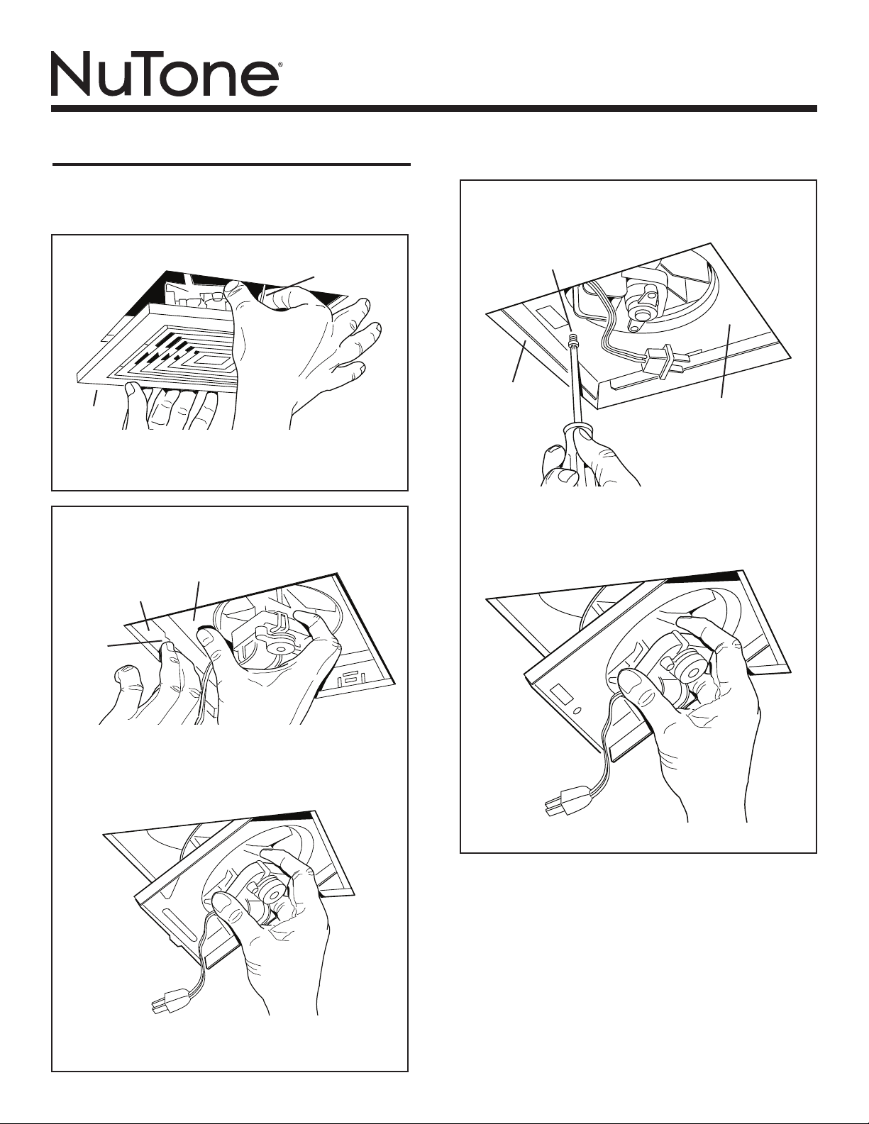
2. Remove the grille from the existing fan.
SPRING
GRILLE
Pull grille down to expose two springs. Squeeze each spring
together and pull down again to release springs from motor
plate slots.
-- D-HOUSING FAN ONLY --
3. Remove blower assembly from existing fan.
MOTOR PLATE
SIDE OF HOUSING
-- 690 SERIES FAN ONLY --
3. Remove blower assembly from existing fan.
SCREW
SIDE OF
HOUSING
Unplug motor cord from receptacle and remove screw located
next to receptacle. If necessary, insert a straight-blade screwdriver between motor plate and side of housing near the screw
location and gently pry housing away from motor plate.
MOTOR PLATE
TAB
Unplug motor cord from receptacle. Find the single tab on
the motor plate. Push up on motor plate near tab while pushing out on side of housing. Or insert a straight-blade screwdriver into slot in housing next to tab and twist screwdriver.
When motor plate tab disengages from housing slot, pivot
blower assembly down and out.
Pivot blower assembly down and out.
4. Check existing housing.
Vacuum the interior of the existing fan housing with a
dusting brush attachment. Examine the housing to make
sure it is securely fastened to the building structure and
free of any holes caused by corrosion. The receptacle
must be intact. If any damage is found, do not continue
installation of this product. Contact a qualified person(s)
for repair.
5. Compare old and new motor plates.
One of the two new motor plates is the same size as the
motor plate from the existing fan. Use this motor plate in
step 6.
Page 3
MODEL 690NT
Page 3
6. Attach the new motor plate to the new wheel/
motor assembly.
NEW
WHEEL/MOTOR
ASSEMBLY
NOTCH
NEW
MOTOR PLATE
(“690” SERIES)
NEW
WHEEL/MOTOR
ASSEMBLY
NEW
MOTOR PLATE
(“D” HOUSING)
CAUTION:
ROUTE
MOTOR WIRES
AS SHOWN
NOTCH
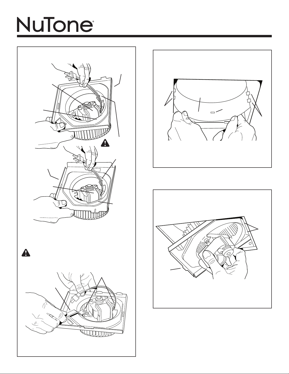
7. Insert the new scroll band into the existing fan
housing.
Note: Skip this step if the existing fan housing already con-
tains a scroll band (plastic or metal).
NEW
SCROLL
BAND
DOUBLE
TABS
Bend it into a crescent shape and align one of the small
slots in the scroll band with the single tab in the fan housing. Place the ends of the scroll band behind the double
tabs in the fan housing, and release the scroll band.
SINGLE
TAB
DOUBLE
TABS
-- D-HOUSING FAN ONLY --
8. Install new blower assembly into existing fan
housing.
Set the new wheel/motor assembly on a flat surface with
the motor facing up. Orient the new motor plate so that the
specification label faces up and the motor body fits into the
wide notch in the motor plate.
CAUTION: The motor lead wires must be routed through
the motor plate as shown. Wires routed differently will
become pinched or cut when the motor plate is installed into
the housing. Electrical shock may result.
2 NUTS
WRENCH
Place the new motor plate onto the motor bracket studs.
Fasten parts together securely using two nuts and wrench
provided.
2 TABS
&
SLOTS
TAB
Insert two motor plate tabs into slots in housing and pivot
blower assembly up until the third motor plate tab snaps
into matching slot in housing. Make sure tabs hold blower
assembly securely in place. Plug in motor.
Page 4

MODEL 690NT
1
2
3
4
5
5
6
7
8
9
Page 4
-- 690 SERIES FAN ONLY --
8. Install new blower assembly into existing fan
housing.
SCREW
2 TABS
&
SLOTS
Insert two motor plate tabs into slots in housing and pivot
blower assembly up until it is touching the wiring box. Secure in place with screw provided. Plug in motor.
SERVICE PARTS
Key No. Part No. Description
1 97016777 Grille Assembly (includes key no. 2)
2 99140198 Grille Spring (2 required)
3 98010267 Motor Plate (“D-Housing” fans)
4 98010268 Motor Plate (“690” Series fans)
5 99260423 Nut, Hex Flange #8-32 (2 required)
6 99150625 Screw #8-18 X .375
97016924 Parts Bag (includes key nos. 5 & 6)
7 97016941 Motor/Bracket Assembly
8 97016962 Wheel
97016923 Wheel/Motor Assembly
(includes key nos. 7 & 8)
9 99111346 Scroll Band
Order replacement parts by “Part No.”, not by “Key No.”
9. Install new grille.
GRILLE
MOTOR
PLATE
SPRING
NEW GRILLE
Squeeze one grille spring together and insert it into the
matching slot in motor plate. Repeat with the other grille
spring.
Push grille until it is tight against ceiling or wall.
99043583C
Page 5

MODELO 690NT
Garantía Limitada de un Año
GARANTÍA DEL PROPIETARIO: NuTone garantiza al comprador consumidor
original de sus productos, por el período de un (1) año desde la fecha original de
compra, que tales productos están libres de defectos en material y mano de
obra. NO HAY OTRAS GARANTÍAS, EXPRESADAS O SOBREENTENDIDAS,
INCLUYENDO, PERO NO LIMITADAS A, GARANTÍAS NO EXPRESADAS DE
MERCANTIBILIDAD O ADAPTABLES A UN PROPÓSITO EN PARTICULAR.
Durante este período de un año, NuTone reparará o reemplazará a su opción
y sin costo, cualquier producto o parte que se encuentre defectuoso bajo
condiciones normales de uso y servicio. ESTA GARANTÍA NO CUBRE A LOS
ARRANCADORES PARA LÁMPARAS FLUORESCENTES O A LOS TUBOS
FLUORESCENTES, FILTROS, DUCTOS, TAPAS DE TECHO, TAPAS DE
PARED Y OTROS ACCESORIOS PARA CANALIZACIÓN. Esta garantía no
cubre (a) Mantenimiento y servicios normales (b) Productos o partes sujetos al
mal uso, negligencia, accidente, mantenimiento inadecuado o reparaciones (por
otros ajenos a NuTone), instalación defectuosa o a una instalación contraria a
las instrucciones de instalación recomendadas.
La duración de cualquier garantía no expresada está limitada a un período de un
año según se especifica en la garantía expresada. Algunos estados no permiten
limitación en cuanto a la duración de una garantía no expresada, por lo que la
limitación arriba indicada puede que no se aplique a Ud.
LA OBLIGACIÓN DE NUTONE DE REPARAR O REEMPLAZAR A SU
OPCIÓN, SERÁ EL ÚNICO Y EXCLUSIVO RECURSO QUE TENDRÁ EL
COMPRADOR BAJO ESTA GARANTÍA. NUTONE NO SERÁ RESPONSABLE
POR DAÑOS INCIDENTALES, CONSECUENTES O ESPECIALES QUE
RESULTEN A CONSECUENCIA O SEAN INDEPENDIENTE DEL USO O
DESEMPEÑO DEL PRODUCTO. Algunos estados no permiten la exclusión o
limitación de daños incidentales o consecuentes, de modo que la limitación o
exclusión arriba indicada pueda que no se aplique a Ud. Esta garantía le
proporciona derechos legales específicos, y Ud. puede tener otros derechos, los
cuales varían de estado a estado. Esta garantía reemplaza a todas las
garantías anteriores.
SERVICIO DE GARANTÍA: Para tener derecho al servicio de garantía, Ud.
debe (a) Notificar a NuTone a la dirección indicada más abajo o al teléfono
1/800-543-8687, (b) indicar el número de modelo y la identificación de la
parte y (c) describir la naturaleza de cualquier defecto en el producto o
parte. Al momento de solicitar el servicio por la garantía, Ud. debe
presentar la evidencia de la fecha original de compra.
Date d’installation Entrepreneur ou installateur
N° de modèle et description du produit
SI NECESITA ASISTENCIA O SERIVIVIO:
Para obtener la localización del Centro de Servicio Autorizado:
Los residentes de los Estados Unidos contiguos llam gratis al: 1 800 543 8687
Por favor, esté preparado para suministrar • Fecha y prueba de compra
• La naturaleza de la dificultad
Los residentes de Alaska o Hawaii deben escribir a: NuTone Inc. Attn:
Department of National Field Service, 4820 Red Bank Road, Cincinnati Ohio USA
45227-1599.
Los residentes de Canada: Écrivez à Broan-NuTone Canada , 1140 Tristar Drive,
Mississauga, Ontario Canada L5T 1H9. Rev. 03/2001
JUEGO DE RENOVACIÓN DE
VENTILADOR DE BAÑO
LEA Y CONSERVE ESTAS INSTRUCCIONES
ADVERTENCIA
PARA REDUCIR EL RIESGO DE INCENDIOS, DESCARGAS ELÉCTRICAS
O LESIONES PERSONALES, OBSERVE LAS SIGUIENTES PRECAUCIONES:
1. Use la unidad sólo de la manera indicada por el fabricante. Si tiene
preguntas, comuníquese con el fabricante.
2. Antes de dar servicio a la unidad o de limpiarla, interrumpa el suministro eléctrico en el panel de servicio. Bloquee el panel de servicio
o póngale una etiqueta de seguridad para evitar que alguien conecte
accidentalmente la energía eléctrica.
3.
El trabajo de instalación y cableado eléctrico (incluida la ubicación
del interruptor) debe ser realizado por personal calificado y de
conformidad con los códigos y normas correspondientes.
4. Proporcione suficiente aire para que se lleve a cabo una combustión
y descarga adecuadas de los gases a través del tubo de humos (chimenea) del equipo quemador de combustible, a fin de evitar los contratiros. Siga las normas de los equipos de combustión tales como las
establecidas en los códigos locales y las publicadas por la Asociación
Nacional de Protección contra Incendios (National Fire Protection
Association, NFPA) y la Sociedad Americana de Ingenieros de Calefacción, Refrigeración y Aire Acondicionado (American Society for
Heating, Refrigeration and Air Conditioning Engineers, ASHRAE).
5. Este producto podría tener bordes afilados. Trabaje con cuidado para
evitar cortadas y abrasiones durante la instalación y la limpieza.
6. Al cortar o perforar a través de la pared o del cielo raso, tenga cuidado
de no dañar el cableado eléctrico ni otros servicios ocultos.
7. Los ventiladores con conductos deben siempre conectarse hacia el
exterior.
8. Esta unidad no está diseñada para utilizarse en cocinas.
9. Es aceptable montar esta unidad sobre bañeras o duchas si se instala
en un circuito de bifurcación protegido con un interruptor de circuito
de falla a tierra (GFCI).
10. Esta unidad debe conectarse a tierra.
11. Esta unidad debe instalarse en cubiertas de ventiladores marcadas
como cubierta “D” (“D-Housing”) o serie “690”. No se pueden usar
otras cubiertas de ventiladores. Para uso exclusivo con los ventiladores
Broan modelos 670, 671, 688, 689, ventiladores Nautilus modelos
N671, N688 y ventiladores NuTone modelos 693, 695, 696N.
PRECAUCIÓN
1. Sólo para usarse como medio de ventilación general. No se use para
descargar materiales ni vapores peligrosos o explosivos.
2. Instale el ventilador a una altura mínima de 1.5 m (5 pies) del
piso.
3. Para evitar daños a los cojinetes del motor e impulsores ruidosos y
no balanceados, mantenga el motor y el motor impulsor al resguardo
de rociados de yeso, polvos de construcción, etc.
4. Lea la información y los requisitos que aparecen en la etiqueta de
especificaciones.
LIMPIEZA Y MANTENIMIENTO
Para registrar este producto visite:
Página 5
www.nutone.com
OPERACIÓN
Accione este ventilador mediante un interruptor de encendido/apagado o
control de velocidad.
GARANTÍA
• Para lograr un funcionamiento silencioso y eficiente, así como también
larga vida y una apariencia atractiva, baje o retire la rejilla y aspire el
interior del ventilador con un accesorio de cepillo para sacudir polvo.
• El motor está permanentemente lubricado y nunca necesitará aceite.
Si los cojinetes del motor están haciendo ruido excesivo o inusitado,
reemplace el motor con el motor de servicio exacto. También debe
reemplazar el impulsor.
• Para retirar el conjunto del ventilador: vea el paso 3 de la página 6.
Page 6

INSTALACIÓN
MODELO 690NT
Página 6
1. Desconecte el suministro eléctrico y bloquee
el panel de servicio para el ventilador existente.
2. Retire la rejilla del ventilador existente.
MUELLE
REJILLA
Tire de la rejilla hacia abajo para exponer dos muelles. Apriete cada muelle y tire nuevamente hacia abajo para aflojar los
muelles de las ranuras de las placas del motor.
-- ÚNICAMENTE PARA VENTILADORES
CON CUBIERTA D --
3. Retire el conjunto del ventilador del ventilador
existente.
LADO DE LA CUBIERTA
PLACA DEL MOTOR
-- ÚNICAMENTE PARA VENTILADORES
DE LA SERIE 690 --
3. Retire el conjunto del ventilador del ventilador
existente.
TORNILLO
LADO DE LA
CUBIERTA
Desenchufe el cable del motor de su receptáculo y saque el
tornillo que está al lado del receptáculo. Si es necesario, introduzca un destornillador de punta recta entre la placa del motor
y el lado de la cubierta (cerca del tornillo), y haga palanca cuidadosamente para sacar la cubierta de la placa del motor.
PLACA DEL MOTOR
LENGÜETA
Desenchufe el cable del motor de su receptáculo. Localice la
lengüeta única de la placa del motor. Empuje hacia arriba la placa del motor cerca de la lengüeta, al mismo tiempo que empuja hacia afuera el lado de la cubierta. O bien,
introduzca un destornillador de punta recta en la ranura de
la cubierta (junto a la lengüeta) y gire el destornillador.
Cuando la lengüeta de la placa del motor se desenganche
de la ranura de la cubierta, saque el conjunto del ventilador girándolo hacia abajo.
Saque el conjunto del ventilador girándolo hacia abajo.
4. Inspeccione la cubierta existente.
Aspire el interior de la cubierta del ventilador existente
con el accesorio de cepillo para sacudir polvo. Compruebe
que la cubierta esté bien sujeta a la estructura de la edificación y libre de agujeros de corrosión. El receptáculo
debe estar intacto. Si tiene cualquier daño, no continúe
instalando este producto. Encargue la reparación a personas debidamente capacitadas.
5. Compare las placas del motor antigua y nueva.
Una de las dos placas nuevas del motor tiene el mismo
tamaño de la placa del motor del ventilador existente. Use
esta placa del motor en el paso 6.
Page 7

MODELO 690NT
Página 7
6. Acople la nueva placa del motor al nuevo con-
junto de rueda/motor.
NUEVO
CONJUNTO DE
RUEDA/MOTOR
MUESCA
NUEVA
PLACA DEL MOTOR
(SERIE “690”)
NUEVO
CONJUNTO DE
RUEDA/MOTOR
NUEVA
PLACA DEL MOTOR
(CUBIERTA “D”)
PRECAUCIÓN:
ENCAMINE
LOS CABLES DEL
MOTOR TAL COMO
SE MUESTRA
MUESCA
7.
Introduzca la nueva banda deslizante en la
cubierta del ventilador existente.
Nota: Omita este paso si la cubierta del ventilador existente ya
contiene una banda deslizante (de plástico o de metal).
NUEVA
BANDA
DESLIZANTE
LENGÜETAS
DOBLES
Dóblela en forma de media luna y alinee una de las ranuras pequeñas
en la banda deslizante con la lengüeta única de la cubierta del ventilador. Coloque los extremos de la banda
deslizante detrás de las lengüetas dobles de la cubierta del
ventilador y afloje la banda deslizante.
LENGÜETA
ÚNICA
LENGÜETAS
DOBLES
-- ÚNICAMENTE PARA VENTILADORES
CON CUBIERTA D --
8. Instale el nuevo conjunto del ventilador en
la cubierta del ventilador existente.
Coloque el nuevo conjunto de rueda/motor en una superficie
plana con el motor de cara hacia arriba. Oriente la nueva
placa del motor de manera que las bridas estén de cara hacia arriba y el cuerpo del motor encaje en la muesca ancha
de la placa del motor.
PRECAUCIÓN: Los cables principales del motor deben en-
caminarse a través de la placa del motor, tal como se muestra. Si los cables se tendieran de forma diferente, podrían quedar
atrapados o cortarse cuando se instale la placa del motor en la
cubierta, y en consecuencia producirse una descarga eléctrica.
2 TUERCAS
LLAVE
Coloque la nueva placa del motor en los pasadores de soporte del motor. Sujete bien las partes con las dos tuercas
y llave incluidas.
2 LENGÜETAS Y RANURAS
LENGÜETA
Inserte dos lengüetas de placa del motor en la cubierta y
gire el conjunto del ventilador hacia arriba hasta que la
tercera lengüeta de la placa del motor encaje en la ranura
coincidente de la cubierta.
mantienen el conjunto del ventilador
Conecte el motor.
Asegúrese de que las lengüetas
bien firme en su sitio.
Page 8

MODELO 690NT
1
2
3
4
5
5
6
7
8
9
Página 8
-- ÚNICAMENTE PARA VENTILADORES
DE LA SERIE 690 --
8.
Instale el nuevo conjunto del ventilador en la
cubierta del ventilador existente.
TORNILLO
2 LENGÜETAS
Y
RANURAS
Inserte dos lengüetas de placa de motor en las ranuras de la
cubierta y gire el conjunto del ventilador hacia arriba hasta
que toque la caja de cableado. Fíjelo con los tornillos incluidos. Conecte el motor.
PIEZAS DE REPUESTO
Clave n.º Pieza n.º Descripción
1 97016777 Conjunto de la rejilla (incluye la clave n.º 2)
2 99140198 Muelle de la rejilla (se requieren 2)
3 98010267 Placa de motor (ventiladores de “cubierta D”)
4 98010268 Placa de motor (ventiladores de la
serie “690”)
5 99260423 Tuerca hexagonal n.º 8-32 (se requieren 2)
6 99150625 Tornillo, n.º 8-18 x 0.375
97016924 Bolsa de piezas (incluye las claves n.º 5 y 6)
7 97016941 Conjunto de motor/soporte
8 97016962 Rueda
97016923 Conjunto de rueda/motor
(incluye las claves n.º 7 y 8)
9 99111346 Banda deslizante
Al hacer el pedido de una pieza de servicio se debe especificar el
número de la pieza (no el número de la clave).
9. Instale la rejilla nueva.
MUELLE DE
PLACA DEL
MOTOR
LA REJILLA
REJILLA NUEVA
Apriete un muelle de la rejilla e introdúzcalo en la ranura
correspondiente en la placa del motor. Repita el procedimiento con el otro muelle de la rejilla.
Empuje la rejilla hasta que esté firme contra el cielo raso o
la pared.
99043583C
 Loading...