

Page 1
READ & SAVE THESE INSTRUCTIONS!
INSTALLATION INSTRUCTIONS
Exhaust Fan
MODELS: 671R & 672R
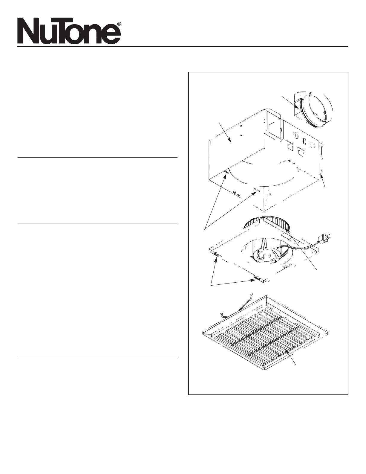
The Exhaust Fan consists of the housing, power unit/blower
assembly (motor, wheel, mounting plate), grille and duct collar.
FAN MUST NOT BE INSTALLED IN A CEILING INSULATED
TO A VALUE GREATER THAN R-40.
SUITABLE FOR USE OVER TUB OR SHOWER ENCLOSURE
WHEN INSTALLED IN A GFCI PROTECTED BRANCH CIRCUIT
.
FOR BEST RESULTS
When installing the Exhaust Fan in a new construction site,
install the housing during the rough-in construction. The blower
unit and grille should be installed after the finished ceiling is in
place.
To install the Exhaust Fan in an existing finished building, an
accessible area is required above the planned location (attic or
crawl space).
IMPORTANT SAFETY INSTRUCTIONS
WARNING: TO REDUCE THE RISK OF FIRE. ELECTRIC
SHOCK, OR INJURY TO PERSONS, OBSERVE THE
FOLLOWING:
A. Use this unit only in the manner intended by the
manufacturer. If you have questions, contact the
manufacturer.
B. Before servicing or cleaning unit, switch power off at service
panel and lock service panel to prevent power from being
switched on accidentally.
When the service disconnecting means cannot be locked,
securely fasten a prominent warning device, such as a tag,
to the service panel.
CAUTION:
For general ventilating use only. Do not use to exhaust
hazardous or explosive materials and vapors.
WARNING: To reduce the risk of fire or electric shock, do not
use this fan with any solid-state speed control.
INSTALLATION INSTRUCTIONS
WARNING: TO REDUCE THE RISK OF FIRE, ELECTRIC
SHOCK, OR INJURY TO PERSONS, OBSERVE THE
FOLLOWING:
A. Installation work and electrical wiring must be done by
qualified person(s) in accordance with all applicable codes
and standards, including fire-rated construction.
B. Sufficient air is needed for proper combustion and
exhausting of gases through the flue (chimney) of fuel
burning equipment to prevent back drafting. Follow the
heating equipment manufacturer's guideline and safety
standards such as those published by the National Fire
Protection Association (NFPA), and the American Society for
Heating, Refrigeration and Air Conditioning Engineers
(ASHRAE), and the local code authorities.
FIGURE 1
DUCT COLLAR
HOUSING
SLOTS
POWER UNIT/BLOWER
ASSEMBLY
MOUNTING TAB
TABS
GRILLE
C. When cutting or drilling into wall or ceiling, do not damage
electrical wiring and other hidden utilities.
D. Ducted fans must always be vented to the outdoors.
E. If this unit is to be installed over a tub or shower, it must be
marked as appropriate for the application and be connected
to a GFCI (Ground Fault Circuit Interrupter) protected branch
circuit.
F. NEVER place a switch where it can be reached from a tub or
shower.
COLLIER DE GAINE
BOITER
FENTES
ENSEMBLE MOTEUR/
VENTILATEUR
LA GRILLE
PATTES
PATTES DE MONTAGE
Page 2
PLANNING DUCTWORK AND WIRING
Ductwork
1. Use 4" round duct.
2. Plan to run duct from discharge opening of fan to the
outside. For best fan performance, make the duct run as
short as possible and use a minimum number of elbows.
3. Use optional ducting accessories as required.
Wiring
Plan to run 120vAC house wiring (with ground) from the
power source through a standard wall switch.
Preparation
1. Refer to Figure 1. Remove blower/power unit assembly
from the housing.
(a) Unplug the power unit.
(b) Remove the screw (located next to plug-in receptacle)
which holds blower/power unit mounting plate in place.
Do not misplace this screw.
(c) Lift the mounting plate at the end near the plug-in
receptacle until blower wheel clears the scroll.
(d) Remove plate by pulling its tabs out of slots in the
housing. Set blower/power unit aside until needed.
2. Remove one of the wiring knockouts from housing.
MOUNTING THE HOUSING
Mounting Using Mounting Tabs
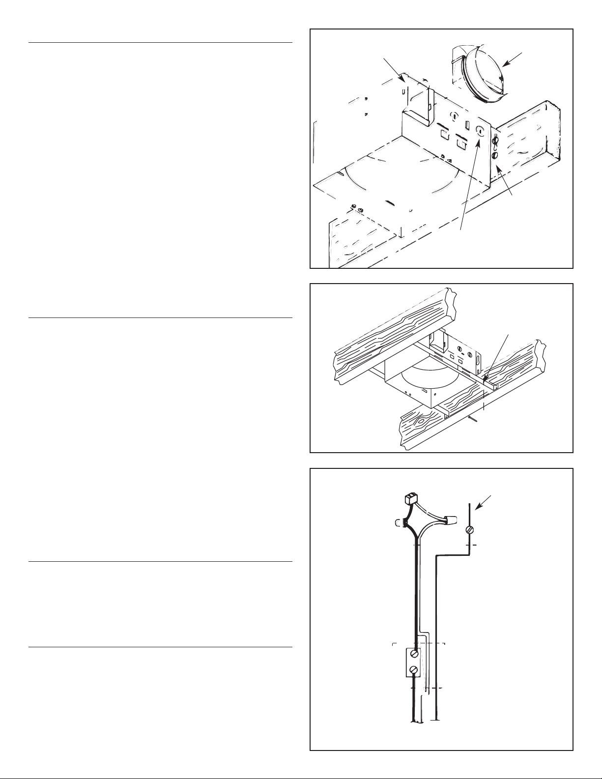
Refer to Figure 2.
1. Locate fan housing next to ceiling joist.
2. Using wood screws (not provided) loosely attach the
housing to ceiling joist through the keyhole slots in
mounting tabs.
3. Adjust housing so that it will be flush with the finished
ceiling. For the grille to fit properly, the housing’s rim must
not extend beyond finished ceiling surface.
4. When housing is properly adjusted, tighten screws in slots.
Mounting Using Hanger Bars
(hanger bars sold separately, order model HB4)
Refer to Figure 3.
1. Insert hanger bars in slots provided in housing.
2. Locate fan housing between joists so that the bottom of the
housing is even with the planned finished ceiling. Extend
the hanger bars to the joists.
3. Use screws or nails (not provided) to secure hanger bars to
ceiling joists.
INSTALLING DUCTWORK
1. Refer to Figure 2. Place duct collar over flanges at
discharge opening of fan. Secure collar by snapping tabs
into slots in flanges.
2. Run 4" round duct from outside to fan’s discharge opening.
3. Connect duct to fan’s duct collar.
WIRING
All wiring must comply with local codes and unit must
be properly grounded.
1. Run 120vAC house wiring (with ground) from wall switch to
fan location.
2. Pull wire through access hole and into junction box.
3. Refer to Figure 4. Use approved wire nuts to connect
house supply wires to fixture as follows: white to white;
black to black. Connect green or bare ground wire to green
ground lead.
FIGURE 4
FIGURE 3
FIGURE 2
DUCT COLLAR
WIRING KNOCKOUT
MOUNTING TAB
FLANGES
GREEN GROUND
LEAD
JUNCTION BOX
SWITCH BOX
STANDARD
WALL SWITCH
(NOT INCLUDED)
120vAC, 60Hz HOUSE
POWER
FIELD GROUNDING WIRE
HANGER BARS
(SOLD SEPARATELY)
COLLIER DE GAINE
PRÉDÉ COUPES
PATTES DE MONTAGE
COLLERETTES
VIS VERTE DE
MISE A LA TERRE
BOITER DE
RACCORDEMENT
BOITER
D’INTERRUPTEUR
COURANT DOMESTIQUE
120V CA, 60 Hz
TERRE
LES BARRES DE
SUSPENSION SONT
VENDUES SÉPARÉMENT
Page 3

POWER/BLOWER UNIT INSTALLATION
1. Place power/blower unit into housing so that mounting
plate’s tabs insert into slots in housing.
2. Press other end of mounting plate down until it is firmly
seated over scroll and plug-in receptacles.
3. Secure mounting plate to housing with provided screw.
4. Refer to Figure 5. Insert motor plug into junction box
receptacle.
GRILLE INSTALLATION
1. Refer to Figure 6. Squeezing grille’s mounting springs
together, insert springs into slots on both sides of the
housing.
2. Press grille firmly into place against ceiling.
INSTALLATION IN EXISTING
CONSTRUCTION
Note: Installation in a finished house requires at least a small
accessible area (attic or crawl space) above the planned
installation location.
1. After determining desired location for fan, drill a small hole
in the ceiling. Place a coat hanger or other stiff wire up
through hole to help in locating from above.
2. Place fan housing on top of ceiling surface and use the
housing as a template to mark area to be cut out.
3. After cutting out opening, mount housing in the opening
using the hanger bars (sold separately), or mount directly
to joist using mounting tabs.
A. Insert hanger bars in slots in housing.
B. Position housing in opening so that bottom of
housing is flush with ceiling.
C. Use screws or nails (not provided) to secure
hanger bars to ceiling joists.
D. Complete installation as described above.
FIGURE 5
FIGURE 6
INSERT TABS
INTO SLOTS
SLOTS
GRILLE
MOUNTING
SPRINGS
FENTES
LA
GRILLE
RESSORT
DE
MONTAGE
LES INSÉRER PATTES
LES FENTES
Product specifications subject to change without notice.
4820 Red Bank Road, Cincinnati, Ohio 45227
Printed in the U.S.A.
, Rev. 1/03, Part No. 87597
One Year Limited Warranty
WARRANTY OWNER: NuTone warrants to the original consumer
purchaser of its products that such products will be free from defects in
materials or workmanship for a period of one (1) year from the date of
original purchase. THERE ARE NO OTHER WARRANTIES, EXPRESS
OR IMPLIED, INCLUDING, BUT NOT LIMITED TO, IMPLIED
WARRANTIES OF MERCHANTABILITY OR FITNESS FOR A
PARTICULAR PURPOSE.
During this one year period, NuTone will, at its option, repair or replace,
without charge, any product or part which is found to be defective under
normal use and service. THIS WARRANTY DOES NOT EXTEND TO
FLUORESCENT LAMP STARTERS OR TUBES, FILTERS, DUCT,
ROOF CAPS, WALL CAPS AND OTHER ACCESSORIESFOR
DUCTING. This warranty does not cover (a) normal maintenance and
service or (b) any products or parts which have been subject to misuse,
negligence, accident, improper maintenance or repair (other than by
NuTone), faulty installation or installation contrary to recommended
installation instructions.
The duration of any implied warranty is limited to the one year period as
specified for the express warranty. Some states do not allow limitation on
how long an implied warranty lasts, so the above limitation may not apply
to you.
NUTONE’S OBLIGATION TO REPAIR OR REPLACE, AT NUTONE’S
OPTION, SHALL BE THE PURCHASER’S SOLE AND EXCLUSIVE
REMEDY UNDER THIS WARRANTY. NUTONE SHALL NOT BE
LIABLE FOR INCIDENTAL, CONSEQUENTIAL OR SPECIAL
DAMAGES ARISING OUT OF OR IN CONNECTION WITH PRODUCT
USE OR PERFORMANCE. Some states do not allow the exclusion or
limitation of incidental or consequential damages, so the above limitation
or exclusion may not apply to you. This warranty gives you specific legal
rights, and you may also have other rights, which vary from state to state.
This warranty supersedes all prior warranties.
WARRANTY SERVICE: To qualify for warranty service, you must
(a) notify NuTone at the address stated below or telephone
1/800-543-8687, (b) give the model number and part identification
and (c) describe the nature of any defect in the product or part.
At the time of requesting warranty service, you must present
evidence of the original purchase date.
Date of Installation Builder or Installer
Model No. and Product Description
IF YOU NEED ASSISTANCE OR SERVICE:
For the location of your nearest NuTone Independent
Authorized Service Center:
Residents of the contiguous United States Dial Free 1-800-543-8687
Please be prepared to provide:
• Product model number • Date and Proof of purchase
• The nature of the difficulty
Residents of Alaska or Hawaii should write to: NuTone Inc.
Attn: Department of National Field Service, 4820 Red Bank Road,
Cincinnati Ohio 45227- 1599.
Residents of Canada should write to: Broan-NuTone Canada,
6300 Tomken Road,Mississauga, Ontario, Canada L5T 1H9.
Rev. 03/2001
Page 4

LEA Y GUARDE ESTAS INSTRUCCIONES
¡
INSTRUCCIONES PARA LA INSTALACION!
Ventilateur d’évacuation
MODELES: 671R et 672R
Le ventilateur comprend: le boîter. le bloc-moteur (moteur,
aubes, plaque de montage), la grille et le collier de gaine.
LE VENTILATEUR NE DOIT PAS ETRE INSTALLE DANS
UN PLAFOND A ISOLATION THERMIQUE SUPERIEURE
A R-40.
UTILISATION POSIBLE AU-DESSUS D'UNE BAIGNOIRE
OU D'UNE DOUCHE LORSQU'IL EST RELIÉ À UN
CIRCUIT PORTÉGÉ PAR DISJONCTEUR DIFFÉRENTIEL.
POUR DE MEILLEURS RESULTATS
Lorsqu’on installe le ventilateur dans une construction
neuve, installer le boîter avant de procéder aux finitions. Le
bloc-moteur et la grille doivent être installés après la finition
du plafond.
Pour installer le ventilateur dans une construction
ancienne, un espace accessible au-dessus de l’emplacement
choisi pour l’installation est exigé (grenier ou combles).
IMPORTANTES DIRECTIVES DE
SÉCURITÉ
AVERTISSEMENT: POUR RÉDUIRE LES RISQUES
D’INCENDIE, DE CHOCS ÉLECTRIQUES OU DE
BLESSURES, RESPECTER CE QUI SUIT:
A. Utiliser cet appareil seulement pour les fins prévues par le
fabricant. Pour toute question, communiquer avec le
fabricant.
B. Avant de faire l’entretien ou le nettoyage de l’appareil,
couper le courant au tableau de distribution et verrouiller ce
dernier pour éviter que le courant ne soit remis
accidentellement.
Lorsque vous ne pouvez verrouiller l'interrupteur, placez
un avertissement clairement visible, par exemple une
étiquette, sur le tableau de distribution.
PRECAUCION:
Solamente para ventilación general. No lo utilice para
expulsar materiales y vapores peligrosos o explosivos.
MISE EN GARDE: Pour réduire les risques d’incendie ou
de choc électrique, n’utilisez pas de commande électronique
de vitesse avec ce ventilateur.
DIRECTIVES D' INSTALLATION
AVERTISSEMENT: POUR RÉDUIRE LES RISQUES
D’INCENDIE, DE CHOC ÉLECTRIQUE OU DE
BLESSURES, RESPECTER CE QUI SUIT:
A. Les travaux d’installation et d’électricité doivent être
confiés à des personnes qualifiées, conformément aux
normes et aux codes en vigueur, notamment en ce qui
concerne les normes de protection contre les incendies.
B. Pour éviter les retours d’air, les appareils de chauffage
doivent avoir suffisamment d’air pour assurer une
combustion et une évacuation appropriées des gaz.
Suivre les directives du fabricant de l’appareil de
chauffage ainsi que les normes de sécurité édictées par
des organismes comme la National Fire Protection
Association (NFPA), l’American Society for Heating,
Refrigeration and Air Conditioning Engineers ou les
organismes de réglementation locaux.
C. Lorsque vous percez les murs et plafonds, éviter
d’endommager les fils électriques et les autres
canalisations.
D. Les ventilateurs dotés de tuyau doivent toujours être
raccordés à l’extérieur.
E. Si cet appareil doit être installé au-dessus d’un bain ou
d’une cabine de douche, il doit être identifié comme
convenant à une telle installation.
F. NE JAMAIS placer un interrupteur à la portée d’une
personne qui se trouverait dans le bain ou la douche.
PREPARATION DU GAINAGE ET DU
CABLAGE
Grainage
1. Utiliser une gaine ronde de 4 pounces.
2. Prévoir le parcours de la gaine pour évacuation à
l’extérieur. Pour de meilleures performances, s’arranger
pour que la gaine soit aussi courte que possible et utiliser
un minimum de coudes.
3. Utiliser les accessoires de gainage NuTone en option.
Câblage
Amener un câble de 120 V CA (avec terre) de la source de
courant en passant par un interrupteur mural standard.
Préparation
1. Voir Figure 1. Enlever le moteur du boîter.
(a) Débrancher le moteur.
(b) Enlever et conserver la vis (placée près de la prise de
branchement) qui retient la plaque de montage du
moteur en place.
(c) Soulever la plaque de montage du côté de la prise de
branchement jusqu’à ce que les aubes du ventilateur
dégagent le rebord.
(d) Enlever la plaque en tirant ses pattes hors des fentes
du boîter. Mettre le moteur de côté.
2. Enlever une des prédé coupes pour le câblage.
MONTAGE DU BOITER
Utilisation des Fixations de Montage
Voir Figure 2.
1. Positionnez l’habitacle à côté d’une traverse de plafond.
2. Utilisez des vis à bois (pas fournies) afin de positionner
librement l’habitacle sur une traverse du plafond au
moyen des ouvertures de forme oblongue sur les
fixations de montage.
3. Ajustez l’habitacle afin de le positionner à fleur avec le
plafond fini.
4. Lorsque l’habitacle est bien positionné, vissez les vis des
fentes.
Page 5

Utilisation de Barres de Suspension
(Les barres de suspension sont vendues
séparément; commandez le modèle HB4)
Voir Figure 3.
1. Insérez les barres de suspension dans les fentes situées
sur l’habitacle.
2. Positionnez l’habitacle de ventilation entre les traverses
du plafond afin que le dessous de l’habitacle du
ventilateur soit positionné à fleur avec le plafond fini.
3. Utilisez des vis ou des pointes pour positionner les
supports de montage sur les traverses du plafond.
INSTALLATION DE LA GAINE
1. Voir Figure 2. Placer le collier de gaine sur les collerettes à
l’ouverture d’évacution du ventilateur. Fixer le collier en
pressant les pattes dans les fentes des collerettes.
2. Faire passer une gaine ronde de 4 po de l’ouverture
d’évacuation du ventilateur à l’extérieur.
3. Raccorder la gaine au collier de gaine du ventilateur.
CABLAGE
Tout le câblage doit respecter les règlements locaux et
le ventilateur doit être convenablement relié à la terre.
1. Amener un câble de 120 V CA (avec terre) de l’interrupteur
mural à l’emplacement du bentilateur.
2. Tirer le câble par le trou d’accès jusque dans le boîter de
raccordement.
3. Voir Figure 4. Utiliser des connecteirs agréés pour
raccorder les câbles d’alimentation générale aux câbles de
l’élément: le blanc avec le blanc, le noir avec le noir.
Raccorder le câble de terre vert ou nu à la vis verte de mise
à la terre.
INSTALLATION DU MOTEUR
1. Placer de moteur dans le boîter de telle sorte que
les pattes de la plaque de montage s’insèrent dans
les fentes du boîter.
2. Apuyer sur l’autre extrémité de la plaque de montage
pour la faire descendre jusqu’à ce qu’elle soit bien installée
au-dessus du rebord et des prises de branchement.
3. Visser la plaque de montage au boîter.
4. Voir Figure 5. Insérer la fiche du moteur dans la prise du
boîter de raccordement.
INSTALLATION DE LA GRILLE
1. Voir Figure 6. En comprimant les ressorts de montage
de la grille, les insérer dans les fentes des deux côtés
du boîter.
2. Appuyer fermement sur la grille pour qu’elle vienne contre le
plafond.
INSTALLATION DANS UNE
CONSTRUCTION EXISTANTE
PLANIFICATION
L’installation dans une maison déjà terminée demande au
moins un petit espace accessible audessus de
l’emplacement de l’installation choisi (grenier ou débarras).
1. Après avoir déterminé l’endroit de l’emplacement du
ventilateur percez un petit trou dans le plafond.
2. Placez l’habitacle du ventilateur sur la surface du plafond
et utilisez-le comme gabarit pour marquer les limites de la
découpe.
3. Après avoir fait l’ouverture, monez l’habitacle dans
l’ouverture en utilisant les barres de suspension
(vendues séparément),ou fixez-le directement aux solives,
au moyen des fixations de montage.
A. Introduisez les barres de suspension dans les
ouvertures de l’habitacle.
B. Positionnez l’habitacle dans l’ouverture afin
d’avoir le bas de celui-ci à fleur avec le plafond.
C. Utilisez des vis ou des pointes (pas fournies) afin
de positionner les barres de suspension sur les
traverses du plafond.
D. Finissez l’installation comme décrite au-dessu.
Les caracteristiques des produits peuvent changer sans préavis.
4820 Red Bank Road, Cincinnati, Ohio 45227
Imprimé aux E.-U., Rev. 1/03, Part No. 87597
Garantie limitée d’un an
GARANTIE DU PROPRIÉTAIRE: NuTone garantie à l'acheteur original
de ses produits que ces derniers seront exempts de tout défaut de
matériaux et de fabrication pour une période d’un (1) an à compter de la
date d'achat. AUCUNE AUTRE GARANTIE, IMPLICITE OU
EXPRESSE, N'EST DONNÉE, Y COMPRIS, MAIS SANS S'Y LIMITER,
GARANTIE DE MARCHANDIBILITÉ OU D'ADAPTATION À UN
USAGE PARTICULIER.
Pendant cette période d’un an, NuTone procédera au remplacement ou
à la réparation sans aucuns frais, mais à sa propre discrétion, de tout
produit ou pièce jugé défectueux dans le cadre d'une utilisation normale.
CETTE GARANTIE NE VISE PAS LES DISPOSITIFS D'AMORÇAGE NI
LES TUBES DES LUMINAIRES FLUORESCENTS. Cette garantie ne
couvre pas (a) l'entretien et le service courants ni (b) les produits et les
pièces ayant fait l'objet d'un usage abusif, de négligence, d'un accident,
d'un entretien ou d'une réparation non appropriée (par du personnel non
autorisé par NuTone), d'une mauvaise installation ou d'une installation
non conforme aux directives d'installation fournies.
La durée de toute garantie implicite est limitée à la période de deux ans
précisée pour la garantie expresse. Certains états ne reconnaissent pas
les restrictions relatives à la durée des garanties implicites; il se pourrait
donc que cette restriction ne s'applique pas dans votre cas.
LE REMPLACEMENT OU LA RÉPARATION PAR NUTONE, À SA
PROPRE DISCRÉTION, DE TOUT PRODUIT OU PIÈCE DÉFECTUEUX
CONSTITUE LE SEUL REMÈDE DE L'ACHETEUR EN VERTU DE
CETTE GARANTIE. NUTONE NE PEUT ÊTRE TENUE
RESPONSABLE DES DOMMAGES INDIRECTS, CONSÉCUTIFS OU
SPÉCIAUX ATTRIBUABLES À L'UTILISATION OU AU RENDEMENT
DU PRODUIT. Certains états ne reconnaissent pas les restrictions ni les
exclusions relatives aux dommages indirects, consécutifs ou spéciaux; il
se pourrait donc que cette restriction ne s'applique pas dans votre cas. La
présente garantie vous accorde des droits spécifiques, mais vous
pourriez aussi avoir d'autres droits en fonction de l'état dans lequel vous
résidez. Cette garantie remplace toute autre garantie donnée
précédemment.
SERVICE SOUS GARANTIE Pour être admissible au service sous
garantie, vous devez (a) aviser NuTone, à l'adresse fournie cidessous ou par téléphone au 1 800 543-3687, (b) fournir le numéro
du modèle et la description de la pièce et (c) décrire la nature du
défaut de la pièce ou du produit. Au moment de la demande de
service sous garantie, vous devez fournir une preuve de la date
d'achat originale.
Date d’installation Entrepreneur ou installateur
N° de modèle et description du produit
POUR OBTENIR DE L’ASSISTANCE OU DU SERVICE:
Pour connaître le Centre de service NuTone autorisé
indépendant le plus proche:
Résidents des États-Unis continentaux,
composez le numéro sans frais: 1 800 543 8687
• Garder à protée de la main le numéro du modèle
• La date et la preuve d’achat • Le type de problème.
Résidents de l’Alaska et d’Hawaii: Écrivez à NuTone Inc.
Attn: Department of National Field Service, 4820 Red Bank Road,
Cincinnati Ohio USA 45227- 1599.
Résidents du Canada: Écrivez à Broan-NuTone Canada,
1140 Tristar Drive, Mississauga, Ontario Canada L5T 1H9.
Rev. 03/2001
Page 6

671R, 672R
Rev.
DECEMBER
1999
CURRENT
ORIGINAL MODEL USED ON
REPLACEMENT
REF.
PART NO.
PART DESCRIPTION
PART NO.
1 86863 MOTOR MOUNTING PLATE 671R, 672R 86863-000
2 32787 MOTOR ISOLATION MOUNT 671R, 672R 32787-000
3 32788 GROUND CLIP 671R, 672R 32788-000
86933 MOTOR 672R 86933-000
87594 MOTOR 671R 87594-000
5 51919 BLOWER WHEEL 671R, 672R 5900A-000
6 63007 PUSH NUT 671R, 672R 63007-000
7 30652 DUCT ADAPTER ASSY 671R, 672R 30652-000
8 56885 GRILLE AND SPRING ASSY 671R, 672R 56885-000
9 10034 RECEPTACLE 671R, 672R 10034-000
EFFECTIVE
DATE
PRODUCT
GROUP
FAN
MODEL NUMBER
PARTS LIST
NOTE: Always order by
current part number
®
NuTone
Attn: Parts Department
4820 Red Bank Rd.
Cincinnati, OH 45227-1599
Phone: (513) 527-5426
Fax: (513) 527-5173
671R, 672R I.I.
4
3
6
7
9
8
5
4
1
2
 Loading...