

Page 1

Industrial instrumentation for P ressure and Temperature
User Guide
ENG
PRESSURE TRANSMITTER SX SERIES
II 1GD Ex ia IIC T6 Ex ia IIIC T85°C
II 1/2GD Ex ia IIC T6 Ex ia IIIC T85°C
Index
8.1.1 IMPORTANT INFORMATION ____________________________________________________________ 2
8.1.2 FUNCTION _____________________________________________________________________________ 2
8.1.3 APPLICATION __________________________________________________________________________ 2
8.1.4 CLASSIFICATION _______________________________________________________________________ 2
8.1.5 ELECTRICAL CHARACTERISTIC ________________________________________________________ 2
8.1.6 ELECTRICAL CONNECTION_____________________________________________________________ 3
8.1.7 SAFETY INSTRUCTIONS ________________________________________________________________ 3
8.1.8 COMMISSIONING _______________________________________________________________________ 3
8.1.9 RESETTING AND MAINTENANCE ________________________________________________________ 4
Via C. Battisti, 5 9/ 61 – 28045 INVORIO (No) – Italy
Tel. +39 0322 253200 – Fax +39 0322 253232
www.nuovafima.com – e-mail: [email protected]
Copyright Nuova Fima S.r.l.
IIIC_ENG_3 11/2016
All rights reserved. Any part of this publication should not be
reproduced without a written Nuova Fima’s S.r.l. approval
IIIC_II1-2GD-Ex-ia-IIC-T6-Ex-ia-
MI-SX-II-1GD-Ex-ia-IIC-T6-Ex-ia-
4123 Hollister, Suite G – TX 77080 Houston
Tel. +1 713.690.9800 – Fax +1 713.690.980 3
www.nuovafima.com – e-mail: [email protected]
Page 2

User Guide
2
Industrial instrumentation for Pressure and Temperature
8.1.1 Important information
8.1.2 Function
8.1.3 Application
8.1.4 Classification
T6 (T85°C) @ Ta≤60°C
T4 (T135°C) @ Ta≤100°C
T6 (T85°C) @ Ta≤60°C
T4 (T135°C) @ Ta≤100°C
8.1.5 Electrical characteristic
Power supply voltage:
(8)10 … 30 V
Output:
4 … 20 mA
Ui (maximum voltag e ):
30 Vdc
Ii (corrente massima):
100 mA
Pi (maximum current):
1 W
Ci (equivalent internal capacity):
19 nF
Ci (equivalent internal capacity + perman ent cab le):
19 nF + 0,2 nF/m
Li (equivalent internal inductance ):
~ 0
Li (equivalent internal inductance + perm anent cable):
~ 0 + 2 µH/m
PRESSURE TRANSMITTER SX SERIES
Read this instruction manual carefully before installing and commissioning the unit. Keep it in a safe place, where it is
accessible to users at any time.
The safety of any instrument results from the careful selection of the model and installation in the system, as well as from
compliance with the maintenance procedures drawn up by the manufacturer. The persons tasked with the selection, installation
and maintenance must be able to recognise the conditions that have a negative impact on the instrument's ability to perform its
function and which may lead to premature breakage or failure. Therefore, qualified, trained technicians are to be employed for
carrying out the procedures laid down in the plant regulations.
Incorrect use may result in damage to the instrument, and possibly cause breakage or damage to personnel or the plant.
In order to correctly select the functional and constructive characteristics of the instruments, we recommend consulting the most
up-to-date version of the catalogue data sheets, available on-line at the websi te www.nuovafima.com
The user is entirely responsible for ensuring correct installation and maintenance.
Directive requirements Reference to Standards
ATEX 2014/34/EU CEI EN 60079-0 CEI EN 60079-11
CEI EN 60079-26 UNI EN 1127-1
The pressure transmitter is used to transform an input pressure into an electrical 4 - 20 mA output signal.
The electrical signal changes in proportion to the input pressure applied.
The SX series of pressure transmitters are used for measuring the pressure of liquid and gas fluids, and are su it abl e fo r
use in places in which there is a risk of explosion. Ambient and process temperatures must be within the limits stated
on the tag.
II 1GD Ex ia IIC T6 Ex ia IIIC T85°C
II 1/2GD Ex ia IIC T6 Ex ia IIIC T85°C
T5 (T100°C) @ Ta≤80°C
T5 (T100°C) @ Ta≤80°C
( ) For some configurations the minimum power supply voltage is 8 V.
NUOVA FIMA -
Page 3
User Guide
3
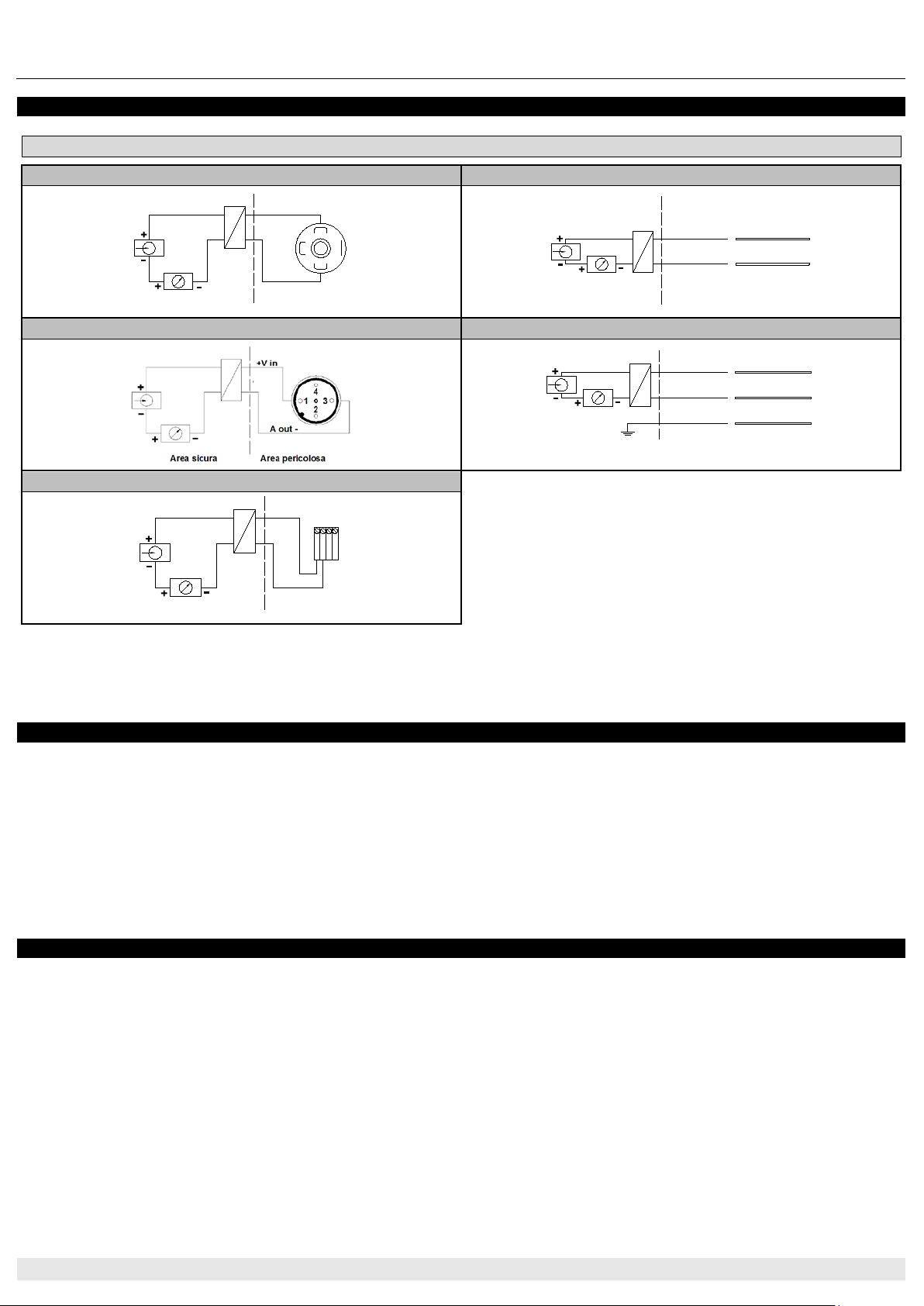
8.1.6 Electrical connection
Wiring diagrams
EN175301-803 connectors
Cable outlet
1
3
2
+V in
A out -
Area pericolosa
Area sicura
Area sicura Area pericolosa
+V in
A out -
Marrone
Bianco
M12x1 connectors
Permanent cable - immersion
A out -
+V in
Area pericolosaArea sicura
Field case
+V in
A out -
Area pericolosaArea sicura
12 34
8.1.7 Safety instructions
8.1.8 Commissioning
PRESSURE TRANSMITTER SX SERIES
The transmitter’s metal case must always be connected to the earth using the threaded connector for the process, in order to
protect it against fluctuations due to electromagnetic fields and electrostatic charges. If this cannot be done, connect the
transmitter to earth using the connector and the shield on the cable.
The transmitter must be connected to an Associated piece of Equipment (Diode safety barrier or Galvanic insulator) with an [Ex
ia] or [Ex ib] execution, complying with the maximum voltage (Ui), current (Ii), and power (Pi), and taking into consideration
the internal capacity (Ci) and inductance (Li) values, indicated in the “Nominal Characteristics”. If the barrier has an “ib”
protection level, the entire system should be at an “ib” level suitable only for not inflammable fluids.
The transmitters must be installed in compliance with the European Standard CEI EN 60079-14 (current edition) and
maintenance operations must be carried out according to the requirements of the European Standard CEI EN 60079-17 (current
edition); Every Intrinsic Safety transmitter must be included in the Document Describing the System (CEI EN 60079-14 and CEI
EN 60079-25).
Before an electrical safety structure is commissioned within a plant or a system, the user must check that it complies with the
design data and is installed correctly. Check that the Associated Equipment called for in the relevant Document Describing the
System is connected to each transmitter.
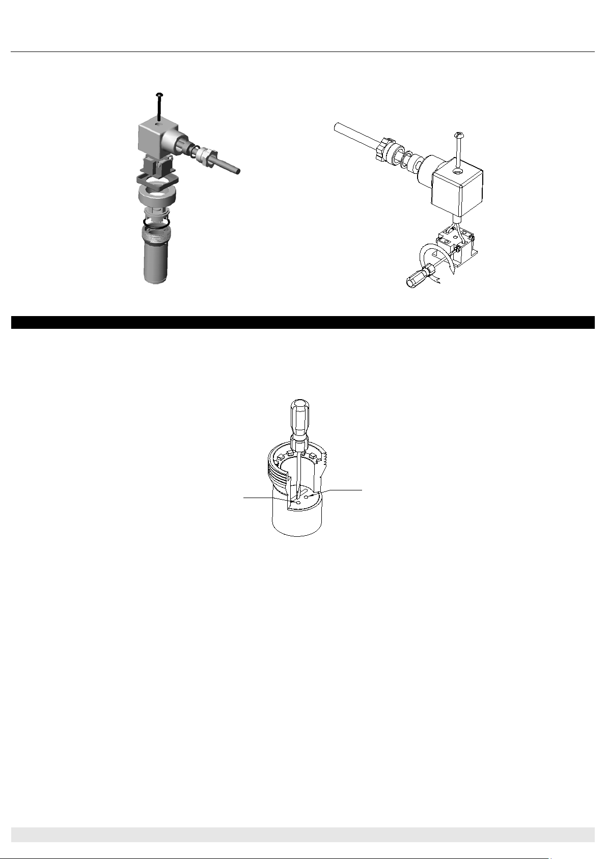
Tighten the threaded portion of the transmitter, applying a torque (max 50 Nm) using a suitable spanner on the hexagonal part of
the process connector, without applying force to the casing with your hands or pipe wrench. Remove the connector as shown in
figure 1 and connect the cable as shown in figure 2. Refit the connector, complete with all its gaskets, to guarantee the declared
IP protection level, and fix it to the transmitter.
NUOVA FIMA - Industrial instrumentation for Pressure and Temperature
Page 4
User Guide
4
Industrial instrumentation for Pressure and Temperature
8.1.9 Resetting and maintenance
S=span
Z=zero
PRESSURE TRANSMITTER SX SERIES
The IP grade according to standard CEI EN 60529 is guaranteed only if the female connector equipped with a connection
cable is mounted on the instrument and all the other components are assembled correctly.
Figure 1 - Exploded view of the connector Figure 2 - Connecting the wires
For the versions available, the zero and the scale span can be adjusted as follows:
- Removing the connector (see figure 1)
- Setting the zero (Z)
- Setting the span (S)
Figura 3 - Setting
Maintenance operations are to be entrusted to duly qualified personnel that are trained on the specific characteristics of the
equipment and the Intrinsic safety technique, and they are to comply fully with the provisions of the CEI EN 60079-17 European
standard (current edition).
The SX series of transmitters is “maintenance free”. The resetting cycle depend s on the appli cation they are used for.
Suggested setting frequency: 1 year. If a fault occurs, contact NUOVA FIMA S.r.l.
Using transmitters that have been subjected to work not explicitly authorised by NUOVA FIMA S.r.l. relieves the Company of
any and all responsibility and causes the contractual guarantee to become null and void.
NUOVA FIMA -
Page 5

Il presente documento è sottoposto a gestione controllata e non può essere riprodotto senza autorizzazione di NUOVA FIMA s.r.l.
This document is issued as controlled copy and it can not be reproduced without NUOVA FIMA licence.
•
•
•
•
DRAFT
Industrial Instrumentation for Pressure and Temperature
Via C.Battisti 59 - 28045 INVORIO (NO) -Italy
Tel. +39 0322 253200 - Fax +39 0322 253232
www.nuovafima.com – [email protected]
DICHIARAZIONE UE DI CONFORMITÀ
EU DECLARATION OF CONFORMITY
NUOVA FIMA s.r.l. dichiara sotto la propria responsabilità che i seguenti strumenti
NUOVA FIMA s.r.l. declares on its sole responsibility that the following s instruments
Trasmettitori di Pressione serie SX
Pressure Transmitters SX series
Sono conformi ai requisiti delle Direttive e sono marcat i - Fulfill the requirements of
the Directives and they are
marked.
2014/68/UE (PED)
2014/34/UE (ATEX)
2014/30/UE (EMC)
(1)
Gli strum enti con sovrappres sione applicabile ≤200 bar (massima pressione ammissibile - PS) sono progettati
e fabbricati secondo criteri di buona prassi cos tr uttiva, in accordo con l’articolo 4, par.3 della direttiv a.
Gli strumenti con sovrappressio ne applicabile >200 bar (massima pressione ammissibile - PS) in aggiunta,
sono classificati in CATEG ORIA I e sottopos ti a valutazio ne d ella co nfor mità seco ndo il Mo dulo A – Co ntrollo di
fabbricazione interno.
Instruments with allowab le overpressure value
and manufactured in accordance with sound engineering practice, according to article 4, par. 3 of the
directive.
Instruments with allowable over pressure value >200 bar (maximum allow able pressure – PS) are additionally
classified with CATEGORY I and subje cted to the conformity assessment pro cedure according to Module A Internal production control.
(2)
Gli strumenti sono marcati - Instruments are mar ked
e sono conformi alle norme – and they comply with the standar ds
• EN 60079-0:2012/A11:2013
• EN 60079-11:2012
• EN 60079-26:2015
Hanno la certificazione di tipo 0425 ATEX 2635 relativa al Fascicolo Tecnico TF 4 rev.2, e la sorveglianza
sulla produzione ha la certificazione N° 1591 rilasciate dall’Organism o Notif ic ato ICIM S.p.A. N° 0425.
They have a type certification 0425 ATEX 2635 referred to the Tec hnic al File TF 4 rev.2, and the s ur veillance
for production has the certification N° 1591 iss ued fro m the No tified Body ICIM S.p.A. N° 0425.
(3)
Gli strumenti sono conformi alla norma – Instruments comply with the s tandard
• EN 61326-1:2013
Il controllo della fabbricazione interna degli strumenti è assicurato dal Sistema Qualità secondo ISO 9001
operante in azienda e certificato da ICIM SpA.
The control of internal manufa cturing of the instruments is assured by the Quality Sy stem according to ISO
9001 of the factory, certified by ICIM SpA.
2011/65/CE (RoHS)
II 1GD Ex ia IIC T6/T5/T4 Ex ia IIIC T85/T100/T135°C
II 1/2GD Ex ia IIC T6/T5/T4 Ex ia IIIC T85/T100/T135°C
Invorio, 18.05.2018 F.Zaveri
(1)
(2)
(3)
≤
200 bar (maximum allowable pressure – PS ) are designed
Responsabile ATEX-ATEX Responsible
Data di emissione 18.05.2018 Edizione C0
 Loading...