

Page 1
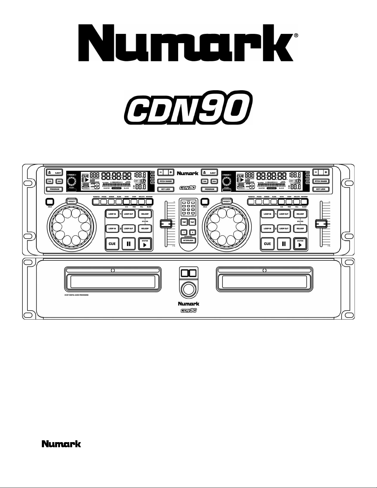
Premium CD Player
MANUAL
©2002 Industries http://www.numark.com
Page 2
CDN90
SAFETY INSTRUCTIONS
a) Read Instructions - All the safety and operating instructions should be read
before this product is connected and used.
Retain Instructions - The safety and operating instructions should be kept
b)
for future reference.
c)
Heed Warnings - All warnings on this product and in these operating
instructions should be followed.
d)
Follow Instructions - All operating and other instructions should be followed.
e) Placement – place the unit in a clean dry location.
f)
Water and Moisture - This product should be kept away from direct contact
with liquids. The apparatus shall not be exposed to dripping or splashing
and that no objects filled with liquids, such as vases, shall be placed on the
apparatus.
Temperature- Avoid placing this product to close to any high heat sources
g)
such as radiators. Do not use this unit at temperatures below 41°F/5°C or
higher than 95°F/35°C.
h)
Ventilation - The appliance should be situated so that it’s location or
position does not interfere with it’s proper ventilation. For example, the
appliance should not be situated on a bed, sofa, rug, or similar surface that
may block the ventilation opening; or, placed in a built-installation, such as
bookcase or cabinet that may impede the flow of air through the ventilation
openings.
i)
Power Sources - This product should be connected to a power supply only
of the type described in these operating instructions, or as marked on the
unit.
j)
Power Cord Protection - Power supply cords should be routed so that they
are not likely to be walked upon or pinched by items placed on or against
them. When removing the cord from a power outlet be sure to remove it by
holding the plug attachment and not by pulling on the cord.
k)
Object and Liquid Entry - Take care that objects do not fall into and that
liquids are not spilled into the inside of the mixer.
l)
Cleaning – The appliance should be cleaned only as recommended by the
manufacturer. Do not use chemical solvents to clean the unit.
m)
Non-use Periods – The power cord of the appliance should be unplugged
from the outlet when left unused for long periods of time.
n)
Damage Requiring Service - Only qualified personnel should service this
product. If you have any questions about service please contact Numark at
the number(s) shown on the back cover of this manual.
o)
Grounding or Polarization - Precautions shoul d be taken so th at the
grounding or polarization means built into the CD player is not defeated.
p)
Internal/External Voltage Selectors - Internal or external voltage selector
switches, if any, should only be reset and re-equipped with a proper plug
for alternative voltage by a qualified service technician. Do not attempt to
alter this yourself.
q)
Carts and Stands -The appliance should be used only with a cart or stand
that is recommended by the manufacturer of the cart or stand. An
appliance and cart combination should be moved with care. Quick stops,
excessive force, and uneven surfaces may cause the appliance and cart
combination to overturn.
Disconnect power cord before servicing
•
Replace critical components
•
recommended equivalents
For AC line powered un it s - Before returning repai red unit to user,
•
use an ohmmeter to measure from both AC plug blades to all exposed
metallic parts. The resistance should be no more than 100,000ohms.
DANGER: INVISIBLE LASER RADIATION WHEN OPEN AND INTERLOCK FAILED OR DEFEATED. AVOID DIRECT EXPOSURE TO BEAM.
USE OF CONTROLS OR ADJUSTMENTS OTHER THAN THOSE SPECIFIED HEREIN MAY RESULT IN HAZARDOUS RADIATION EXPOSURE
SERVICE INSTRUCTIONS
only with factory parts or
CAUTION: TO REDUCE THE RISK OF ELECTRIC SHOCK
DO NOT REMOVE ANY COVER. NO USER-
SERVICEABLE PARTS INSIDE. REFER SERVICING TO
QUALIFIED SERVICE PERSONNEL ONLY.
The lightning flash with arrowhead symbol within the
equilateral triangle is intended to alert the user to the
presence of un-insulated “dangerous voltage” within the
product’s enclosure that may be of sufficient magnitude to
constitute a risk of electric shock.
The exclamation point within the equilateral triangle is
intended to alert the user to the presence of important
operating and maintenance (servicing) instructions in
the literature accompanying this appliance.
FOR USA & CANADIAN MODELS ONLY
TO PREVENT ELECTRIC SHOCK DO NOT USE
THIS (POLARIZED) PLUG WITH AN
EXTENSION CORD, RECEPTACLE OR OTHER
OUTLET UNLESS THE BLADES CAN BE FULLY
INSERTED TO PREVENT BLADE EXPOSURE.
WARNING: To reduce the risk of fire or electrical shock, do not expose this
appliance to rain or moisture. Electrical equipment should NEVER be kept or
stored in damp environments.
NOTICE CONCERNING FCC REGULATIONS
This equipment generates and uses radio frequency energy and may cause
interference to radio and television reception if you do not operate it in strict
accordance with the procedures detailed in this OPERATING MANUAL.
This unit complies with Class B computing device rules in accordance with
the specifications in Sub-part J or Part 15 of the FCC Rules, which are
designed to provide reasonable protection against such interference in a
residential installation. There is no guarantee, however, that interference will
not occur in a particular installation. If the unit does cause interference to any
radio or television reception, try to reduce it by one or more of the following
means:
a) Reposition the other unit and/or its antennae
b) Move this unit
c) Move this unit and the other unit(s) further apart
d) Plug this unit into a different AC outlet so that it is
on a different circuit from the other equipment.
This note is in accordance with Section 15.838 of the FCC Rules.
This unit does not exceed the Class B limits for radio noise emission
from digital apparatus set out in the radio interference regulations of
the Canadian Department of Communications.
CAUTION
DOUBLE INSULATED - When servicing use only identical replacement parts
- The Leader in DJ Technology
©2002 Numark Industries - 2 - http://www.numark.com
Page 3

For 220-volt use in USA, use NEMA style 220-volt plug. For other countries use prop er plug for local outlet.
TABLE OF CONTENTS
Safety and Warnings (PLEASE READ) 2
Table of Contents 3
Introduction Letter from the Engineers and Registration 4
Setup and Connections 5
Description of the Features
Control Unit 6
Main Unit 7
Display 8
CDN90
Basic Operation
Play, Pause, Cue, Pitch, General CD control 9
Advanced Operations
Setting Cue Points 10
Pitch Change, Matching Beats 11
Beatkeeper 12
Key Lock, Key Change, Auto Start 13
Looping 14
Stuttering (Hot Starts) 15
Special Effects 16
Program Functions (A MUST READ!!!) 18
Cue Point Storage 19
MIDI IN-OUT 20
Unit Updates 22
Specifications 23
Warranty 24
- The Leader in DJ Technology
©2002 Numark Industries - 3 - http://www.numark.com
Page 4
CDN90
Features:
PREMIUM CD PLAYER
• Dual rack mount CD Player w/ real
time scratching
• DSP effects, reverse,
• Beatkeeper™ with auto-mixing
capability
• 3,000 cue point and BPM memory
storage
• ±6, 12, 25 & 100% pitch control,
• ±100% KEY LOCK
®
• 2 seamless loops, 3 hot stutter starts
• Adjustable startup & braking speed
• MIDI in/out
• Full Time Digital output
• fader/remote start & relay
• Anti-Shock™
• user upgradeable
• Sleep mode
Dear Customer,
Thank you for making the CDN90 your choice in Premium Dual CD players.
We encourage you to take the time to carefully read this manual to fully enjoy the
capabilities of this product. Many special features can be found on page 18 to
customize your unit to your unique needs. Remember to check online for free
product software updates at
www.numark.com.
The NUMARK Product Development Team
Please record the serial number of your unit as shown on the back of the chassis as well as the name of the dealer from whom you
purchased the unit. Retain this information and your original purchase receipt for your records. Please return the enclosed warranty
card to register your CD player with us.
MODEL: __________________________ PURCHASED FROM:_________________________
SERIAL NUMBER:___________________ DATE OF PURCHASE:________________________
- The Leader in DJ Technology
©2002 Numark Industries - 4 - http://www.numark.com
Page 5
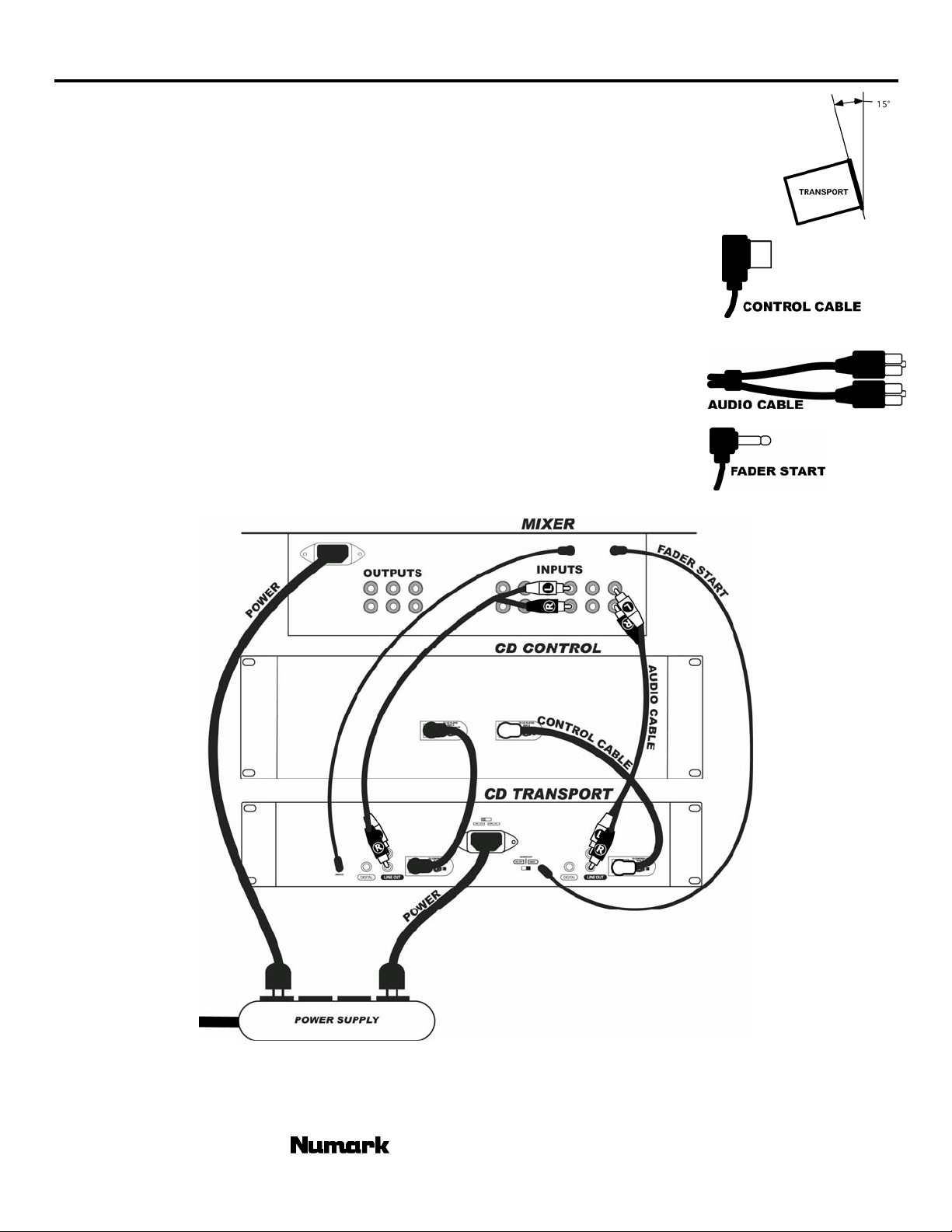
SETUP & CONNECTIONS
Typical connection with a mixer is illustrated below.
1. Mount the units in your console or rack with 19” EIA rails.
2. The transport should be mounted not to exceed an angle of 15 degrees.
3. Your CD player can be affected by excess vibration so mount the units in a secure
environment if possible.
4. Connect the supplied Control Cables between the CD Remote and CD Transport unit.
Note: Be careful to attach the marked connection jacks together, (yellow –yellow and
black-black)
5. Connect the line output connections using the supplied audio cables from the CD
Player to the line inputs of your mixer.
6. Connect Fader start cable. Attach your CD play to a similarly equipped DJ mixer.
(This connection can also be used with a remote switch)
7. Connect IEC power cord to appropriate power source. For US and Canada be sure to
use Polarized power cord and outlets.
CDN90
- The Leader in DJ Technology
©2002 Numark Industries - 5 - http://www.numark.com
Page 6
CDN90
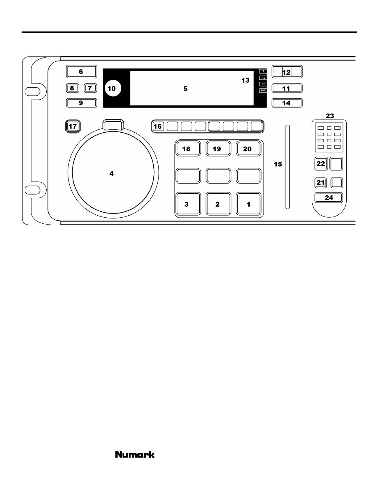
Control Unit Features
1. PLAY/STUTTER- To start the music from the
initial cue point.
2. PAUSE- To pause the music.
3. CUE- To move the music to the cue point and
preview the selection.
4. WHEEL- Used for various functions such as
cueing, scratching, pitch bend, searching, and
effect control
5. LCD DISPLAY- Indicates all the functions, as they
are occurring, with the CD.
6. OPEN/CLOSE- Pressing will open or close the disc
tray on the transport.
7. SNGL- To set play mode in single or continuous
play.
8. TIME- Controls display indication of time mode.
9. PROGRAM- Used for setting track order and
various special commands.
10. TRACK SELECT/SEARCH-
Rotation – selects tracks
Pressing while rotating – selects tracks +10
Pressing once- Puts wheel in search mode.
11. PITCH- Actives and sets pitch slider range.
12. -,+ - Works as pitch bend and controls key and
pitch functions.
13. PITCH RANGE LED- Indicates current pitch range
of the pitch slider
14. KEY- Used for various key control.
15. PITCH SLIDER- Controls the overall speed of the
music.
16. EFFECT BUTTON- Used to determine desired
effect.
17. EFFECT HOLD- Used to set effects to an alternate
position
18. LOOP IN- Used to set stutter and loop in points.
19. LOOP OUT- Used to set loop out points and
release the loop.
20. RELOOP/STUTTER- Used for repeated play
(stutter) from the loop in point, repeating a
previously set, and hot start.
21. AUTO START- Used for setting Relay, Fader, and
Automatic play start.
22. BEAT SYNC - Used for various Beatkeeping
functions.
23. MARCHING BAR GRAPH- Tracks the beats and
measure position of music in both units and
indicates when they match.
24. INTERLOCK- Links both players for beat
alignment.
- The Leader in DJ Technology
©2002 Numark Industries - 6 - http://www.numark.com
Page 7
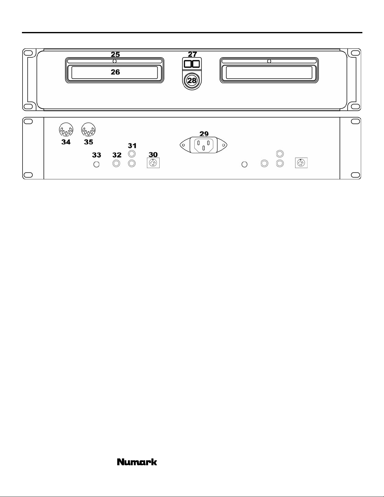
Main Unit Features
25. CD Illumination Light – lights up the CD drawer
and CD when open.
26. CD Drawer – Place your CDs you wish to play in
here. This unit is designed to play commercially
available CD and properly burned and finalized
CDR and CDRW formats. Due to variances on the
specification of certain CD burners and CDs some
discs home made CDs may not play properly.
27. OPEN/CLOSE- Pressing will open or close the disc
tray on the transport.
28. Power Switch- Turn on and turn off the machine
with this button. The unit should always be shut
down with this button first before any external
power is removed. Typically it is recommended
that the CD player is powered on before amplifiers
and off after amplifiers to avoid an audio spike to
be sent through your equipment.
29. IEC Power Plug Connector - Plug your supplied
power cord in here.
30. Control Cable Connector- Plug in the 8-pin cable
included in here to connect the remote control and
main CD unit together
31. RCA Audio Connectors - Connect your CD player
to your mixer from this line level output.
32. Digital Output - This unit has full time digital
output. The format is type 2, form 1, also known
as S/PDIF (Sony/Phillips Digital Interface Format).
Some CDs also have information encoded in the
original audio output such as CDG CDs for
Karaoke. To access this information, hold down
“PROG” followed by “PITCH”. This combination
toggles the digital output to allow raw digital
information to be extracted from the CD for CDG
video purposes. “VIDEO” will be indicated in the
display in this mode. When this mode is active
CDN90
the unit will not allow for looping or other effects
that would disrupt the video. In this mode, Prog +
Cue will turn autocue on and off for video mode
only. This is so that the CDG doesn't skip over the
video frame before the song comes in. When you
wish the digital output with effects to be used only
for other digital devices, the unit should be put into
“Audio” mode.
33. Remote Start Connector – Use this connector to
plug into your fader start compatible mixer or
remote switch. This function is always active.
To use this connector for fader start, connect the
supplied fader start cable to a fader start
compatible mixer. Every time you move the
crossfader on the mixer over to the side that the
unit is on, it will automatically start playing. When
you move the fader away from that side, the unit
will stop. Moving the fader back to the unit side
will start play again.
Foot switches can also be attached to this jack for
creative mixing techniques and can be found in
most music shops. Connector plugs are often ¼”
and an adapter to 1/8” will be needed for
connection. There are also two types of
footswitches that will work with this connector.
The first is a typical, on/off pushbutton switch and
are generally used for switching channels on guitar
amps. The second switch is a momentary
footswitch and is usually used for keyboard sustain
pedals.
34. MIDI IN Connector –The port is for receiving
MIDI (Musical Instrument Digital Interface) signals
from other MIDI devices such as CD players,
Keyboards, or Drum machines.
35. MIDI OUT Connector –The port is for
sending MIDI signals to other MIDI devices.
- The Leader in DJ Technology
©2002 Numark Industries - 7 - http://www.numark.com
Page 8
CDN90
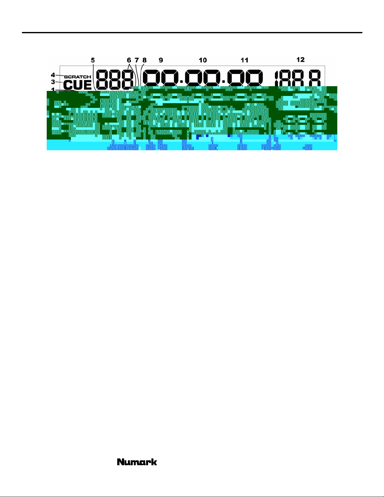
DISPLAY FEATURES
1. PLAY - Active while the unit is actually playing a
CD.
2. PAUSE - Active when the unit is paused.
3. CUE - Flashing when the unit is setting a cue
point. Active when the unit is paused at a cue
point.
4. SCRATCH – indicates when the wheel will cue as a
smooth transition over the music creating a
scratch effect. When not lit the wheel will cue in
the customary stutter style.
5. SINGLE - Shows when the unit is set to play just
one track at a time.
6. TRACK - Shows the track that the unit is playing.
7. PROGRAM – On when a sequence of songs is
preprogrammed into the unit.
8. TOTAL TRACK – shows number of tracks available
on the CD.
9. MINUTES - Shows the minutes elapsed or
remaining depending on mode setting.
10. SECONDS - Shows the seconds elapsed or
remaining depending on mode setting.
11. FRAMES - The CD Player breaks down a second
into 75 frames for accurate cueing. This shows the
frames elapsed or remaining depending on mode
setting.
12. BPM – Indicates the current BPM.
13. KEY – Lights when key effects are active and
indicates key position.
14. LOCK – Lights when key has been locked
15. PITCH – Shows current pitch position.
16. TIME MODE (TOTAL) indicates when full CD
remain time is showing.
17. TIME MODE (REMAIN) shows how much time is
left on a particular track.
18. TIME BAR - Shows either track time remaining,
total CD time remaining or track elapsed time
depending on the setting of the “TIME” button.
Note: The bottom bar will follow the CD when the
“Scratch” effect is on.
19. TIME MODE (ELAPSED) is for showing time as it
is taking place.
20. SEARCH – Shows when the wheel is active for the
search effect.
21. AUTOSTART- Indicates when the CD is set to
relay.
22. HOT – Active when hot points have been set.
23. LOOP INDICATOR – Activates as loops are
playing.
24. 1,2 – Indicates which hot points or loops are set.
25. EFFECT – indicates when wheel is in effect mode.
26. HOLD – indicates when effects are being held in
position.
27. EFFECT PARAMETER – Shows the current effect
setting.
28. MASTER/SLAVE – indicates side dominance in
interlock functions
- The Leader in DJ Technology
©2002 Numark Industries - 8 - http://www.numark.com
Page 9
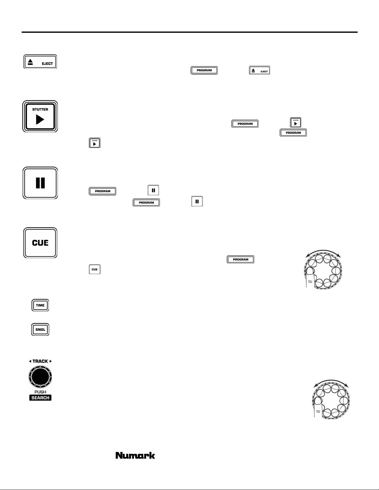
BASIC OPERATIONS
Eject: Press to load or eject the disc. The drawer will automat ically close to protect the tray from
accidental damage while open. NOTE: Tray will not open if the disc is in play. In order to program
the automatic close time press and hold
options of 30 seconds, 60 seconds, 120 seconds, and (no) for no auto close. This setting will be
remembered at power down.
Play/Stutter: Starts the music from either the first set cue poin t or the last point of pause. By starting
from the last pause point while the unit is p aused a new cue point is set. Pressing this button
while the unit is in play restarts the unit from the last cue point, creating a “stutter” effect.
CDN90
followed by . The display will indicate
Startup speed of initial play can be adjusted by pressing
rotating the wheel until the desired seco nds of startup are shown. Pressing
twice will toggle startup between 0 to the desired seconds. This setting will be remembered
Pause: Stops the music while in play. Pressing play following this sets a new cue point. Holding down the
Cue: Returns and pauses the music at the last set cue point. The cue point is the last place in which the
The sound during wheel rotation can be adjusted from a smooth “scratch” sound to
Time: switches the time modes on the d isplay between elapsed playing time, remaining time on the track
Single: toggles the unit to play back just one track at a time (single) or play continuously through all tracks
Track Selection: Rotate the dial to quickly find the desired track. To advance by +10, press the knob
Search: Pressing the selector changes the mode of the jog wheel to a search mode. Search
at power down.
button while scratching or stuttering the music will stop the music at the current position, allowing
you to capture a loop in or cue point. Pause speed (BRAKING) can be adjusted, by pressing
followed by and then rotating the wheel until th e desired seconds of startup are
shown. Pressing
seconds. This setting will be remembered at power down.
unit was paused and then play was pressed. Pressing a second time allows for temporary play of
this point. You can easily edit the cue poin t by turning the wheel. As you rotate the wheel the
music will sound. By stopping the wheel and pressing play a new point is set.
the tradition “stutter” sound. To alternate modes hold
. The display will indicate “SCRATCH” when the scratch sound is active. This
indication will go away when the style of cue is st utter. This setting will be
remembered at power down.
and remaining time on the entire CD. This setting will be remembered at power down.
and then start over repeating the CD infinitely (continuous). This setting will be remembered at
power down.
while rotating.
will remain active while the wheel is being moved and for 8 seconds after. Moving the
wheel clockwise rapidly moves forward through the music. Counterclockwise move s
backwards through the music. There are 2 search speeds depending upon wheel
rotation speed.
followed by twice will toggle startup from 0 to the desired
followed by and then
followed by
followed by
- The Leader in DJ Technology
©2002 Numark Industries - 9 - http://www.numark.com
Page 10

CDN90
SETTING CUE POINTS
PLAY and CUE: Pressing the “PLAY” button starts the disc. Pressing the “CUE” button will reset the disc to the last place where the
disc was started. This is called the cue point. By alternately pressing the “PLAY” button and the “CUE” button, the disc
may be returned and played from the cue point any number of times. This function is called back cue.
PLAY, PAUSE and CUE: Pressing “Play” to start then pressing “Pause” and then “Play” again, a new cue point will be set. Pressing
EDITING CUE POINT: When the jog wheel is turned while paused, a ne w cue point can be located. By pressing “PLAY” while
“Cue” will return to the last pause position and will be the new cue point.
paused that point will be set. By pressing “PLAY” again (STUTTER) th e point can be checked as desirable.
- The Leader in DJ Technology
©2002 Numark Industries - 10 - http://www.numark.com
Page 11

ADJUSTING PITCH
Pitch Range: actives the pitch slider and adjusts the amount of control the pitch slider has on the overall speed of
music. On depression of
100% can be achieved by holding down
options. This setting will be remembered at power down.
Pitch Slider: By moving the slider toward the front the speed of the music speeds up. By moving away the spe ed
slows down. With 100% control the music can be stopped or play at 2 times original speed. To match the
speeds of two units you can either monitor the music of both units by ear or use the au to matic BPM
readout and adjust the pitch to match. When the tempo of the music of the CD you wish to match is slow
compared to the tempo of the other music, move the slider to the (+) end and match the BPM. When
faster, move the pitch slider to the (-) end. By making this adjustment the speeds will be matched though
the beats may not yet be aligned.
Pitch Bend: Buttons and Jog Wheel: Allows the user to temporarily change the speed of the
music to align beats. When the beats of the music of the CD you wish to match is fast
compared to the tempo of the other music press the
clockwise (to the left). When SIDE 2 is behind press the
clockwise (to the right). The pitch changes temporarily while the
pressed or the jog wheel is rotated. The faster you rotate the wheel or the longer you hold
the buttons the more you change. Releasing the button or wheel results in a return to the
original pitch.
CDN90
will toggle the slider on and off. Range adjus tments of 6, 12, 25, and
and then pressing to cycle thr ough the range
or rotate the jog wheel counter
or rotate the jog wheel
or button is being
MATCHING THE BEATS PER MINUTE (BPM)
the tempo of the music of the selected CD side is slow compared to the tempo of the other side, move the slider to the “+” side and
match the BPM. When faster, move the pitch slider to t he “-“ side. The following description is for the case of matching the pitch of
side 2 to the pitch of the music being played o n side 1.
Press “PLAY” on Side 1
Match the tempo by monitoring the music of 2 CD sides by ear or look at the BPM readout and adjusting the pitch. When
Press “PLAY” on Side 2
Listen to Side 2 or look at
the BPM display
Speed Up Side 2 Slow Down Side 2
if Side 2 is slow if Side 2 is fast
compared to Side 1 compared to Side 1
USING PITCH BEND
to temporarily change the pitch. This description is for the case of matching the beat of Side 2 to the beat of the music being played
on Side 1.
After matching the BPM’s, as described above, adjust the pitch temporarily as follows:
If you find the BPM’s (Beats Per Minute or Tempos) are the same, however, the drum beats are not matched you will need
When Side 2 is behind rotate the jog wheel clockwis e When Player 2 is ahead rotate the jog wheel counter-
The pitch changes automatically while the jog wheel is rotated. The faster you rotate the wheel the more you change.
Releasing the wheel results in a r eturn to the original pitch.
or or
clockwise or press
to bend pitch slower. or press to bend pitch faster
- The Leader in DJ Technology
©2002 Numark Industries - 11 - http://www.numark.com
Page 12

CDN90
THE BEATKEEPER™ III and INTERLOCK
tracks beats based upon a combination of frequencies and rhythm patterns in the music. It shows BPM in the
display and outputs 4-count (a.k.a. measure) information about the music in a marching bar graph.
The CDN90 includes the latest Numark patented Beatkeeper™ technology. The Beatkeeper™ automatically
Bar Graph: Most dance music and rock is set up in 4 beat increments called measures. Many of the features within the
TAP: This button is used for resetting the downbeat and also re-calibrating the BPM. The Beatke eper is considered by
INTERLOCK: This button will automatically match the BP M both sides of the CDN90 and lock them together on the
AXIS-8 use this information for incredible results. It’s important to understand the basics of how the
Beatkeeper works to effectively take advantage of other advanced features in the unit. The bottom LED is for
st
the 1
beat or “Down Beat”. Typically most music starts on the downbeat so the unit sets the first beat to
where the music begins. Occasionally this may not be correct or you may wish to reset it. To reset the
downbeat simply tap the
many to be the most accurate automatic beat counter on the market today, however, it occasionally may have
trouble determining the correct BPM. This will happen when the music contains complex rhythms or may start
without a beat at all. If the BPM showing in the display you know is incorrect or the beat LEDs are not flashing
with the beat you have 2 options to reset the Beatkeeper. The first way is to tap
hold for a second. This will tell the unit to search and display the next BPM it finds. If this doesn’t work you
can manually tap
average of your last 8 taps. The Beatkeeper will then know which beats in the music it should be using to
determine the correct BPM and track them through the song. Occasionally the unit will be tracking the
wrong beat but have the correct BPM. To reset the downbeat, simply tap the
downbeat.
SYNCED Bar Graph: This is the middle graph that compares the music from both units. When the
BPM and down beat match the green middle LEDs will also light up indicating a perfect mix when beat
mixing
beat. Before using this function it is important to be sure the Beatkeeper is tracking the correct BPM and is
actually synchronized with the beat. In order to match with control one side is called the master and the
other a slave.
as the master is stopped for any reason the opposite side becomes the n ew master control. Before using this
function it is advisable to activate the key lock since pitch shifts are automatic and can be audible. When
interlock is pressed you will see the BPM display of the slave automatically change to match the master and
the pitch indication in the display change the amount needed to match speeds. Duri ng interlock all pitch
functions of the slave will deactivate and follow everythin g you do with the master. All actions of the slave
such as loop functions and PLAY will now also be beat aligned with the master.
• If both units are playing the slave will adjust to match to the nearest beat of the master.
on the beat and the display will indicate the new BPM. The BPM will be bas ed upon the
The master is always the first unit to be playing. The slave follows the master. As soon
at the new downbeat location as the music is playing or in pause.
on the downbeat and
once on the
• If
• If
When the slave becomes the master or is released from interlock and still playing, the pitch playing will often
be different than the original position o f the pitch slider. The pitch slider will not function until it is brought to
the new position. Move the pitch slider in the direction shown in the display. For example if th e display says
“INCREASE 4.5%” move the slider in the positive direction 4.5% (increase). If it says “DECREASE -3%”
then move the slider in the negative direction 3% (decrease). As you get closer to the correct position the
indication will reduce until yo u ar e at the pitch currently playing. After this has been achieved all pitch
functions will return to the player and pitch can be ad justed as normally. If the unit is stopped for any reason
the pitch will automatically reset to the current position of the slider . Note: Interlock may automatically
deactivate when effects are engaged that can not be beat aligned such as live scratch.
is pressed the slave will now start with the next beat of the master.
is pressed during , the slave will automatically start the next time the master
matches the beat of the slave.
- The Leader in DJ Technology
©2002 Numark Industries - 12 - http://www.numark.com
Page 13

CDN90
KEY LOCK / KEY CHANGE
change it from the current position. This is different than “master tempo” often found on many modern units because the key
lock to the current pitch position and no t automatically set to the “0” pitch posi tion. By doing this we have allowed you to
activate this function while playing without changing the key.
The CDN90 uses Numark exclusive techno logy to lock the key of the music in place at the current pitch position or
Key Lock: Pressing
pitch (tempo) is changed the current key will continue to play. By putting the pitch at 100% you can actually
slow the music to a complete stop while playing the last heard tone s o f the music. This works very well on
vocals and can be a very cool effect. If the unit has Key Lock active after the track has been changed and
before play is hit, the unit will lock to 0. If Key is deactivated during pause the unit will reset to match the
current pitch position.
Key Change: Pressing
new key . The key can increase to 1 octave above normal key or up to 2 octaves above normal key when the
Slide effect is used. The key can decrease up to 5 octaves below normal key. The display will limit to 19 half
steps above or below normal key. If the key is higher, the display will show "H". If it is lower, the display
will show "L".
Auto Start
This button provides 2 functions depending upon the way it is set.
Interlock Play Start: This function was explained in the Beatkeeper section. If
slave will automatically start the next tim e the master matches the beat of the slave.
Relay Play: This function will automatically start play on the side pressed (slave) after completion of the track on the
opposing side (master). In continuo us mode, the relay feature will allow the master to complete playing the full CD then
switch to the slave. In single mode the player will alternate after each track. To activate, press
interlock activated) on the slave side. W hen the master has finished play it will send a signal to the slave to start play. The
slave will start automatically and the master pause and cue to the beginning of the next track. The master w ill now become
the slave.
holds the key in place. The display will indicate to show the current key is locked. If
and then or will change the key. The display will indicat e the and the
is pressed during , the
(without
The relay time of this feature can also be programmed by holding down
appear to relay immediately after the track (0 ), with time added of 1,2,3 or 4 seconds (1,2,3,4), or a reduction of 3,2, or 1
seconds (-3,-2,-1). By reducing time the tracks will crossover before the end of a track, creating an automatic segue from
master to slave. This feature will also work in track sequence program mode; however, if the sides are also in SINGLE mode
the same number of tracks programmed should be the same. Play will stop at the end of the last track.
Fader Start/Remote Switch Start
This function will allow for CD player control using most standard fader start compatible mixers and switches. First you
must follow the directions for connecting to your fader start compatible mixer or switch.
1. Set the CD player to the proper switch mode by holding down followed by tapping
If the display shows then CD player will activate with fader start. Typically if you move the crossfader toward
the active channel, the attached CD player will activate. When it is moved away the unit will cue or pause depending
upon CD player setting.
If the display says
switching channels on guitar amps
If the display says
pedals.
Note: You can also use a momentary sw itch in the ON-OFF switch position . In this case the unit will only play while the
switch is depressed. When the button is release it will either cue or pause depending upon mode
2. Select start/stop mode hold the time button for 2 seconds.
If the display shows
If the display shows then the CD will RE-CUE when stopped.
then the CD player will activate with an ON-OFF pushbutton switch generally used for
then the CD player will activate with a momentary switch usually used for keyboard sustain
then the CD will pause when stopped.
and pressing . Options will
- The Leader in DJ Technology
©2002 Numark Industries - 13 - http://www.numark.com
Page 14

CDN90
LOOPING OPERATIONS
LOOPING: A loop is any area of a CD that you choose to repeat with no breaks. On the CDN90 two seamless loops are possible.
LOOP IN: The “LOOP IN” point is where you wish for the
loop to start. The initial “CUE” point of the CD is also the
default “LOOP IN” point for both loops or “Hot Start” point. If
you wish to set a new “LOOP IN” point, just press
the CD is playing when it reaches the desired point. The
button will light indicating a new loop is set. The
and
point has been set and is accessible for “STUTTER”. By default
the “LOOP IN” also becomes the “STUTTER” or “HOT START”
point.
NOTE: The CD Player will always remember a new set point as the “LOOP IN” or “HOT START” point until
you actually set a new “LOOP IN” point or put in a new CD. The new point will be accessible until you
remove the CD from the unit. If you change tracks and you previously set a “Loop In” on another track,
LOOP OUT: The “LOOP OUT” determines the end point for a loop. The first time you press while a CD is in play
mode, the “LOOP OUT” LED will turn on and flash while the song automatically returns to the “LOOP IN” point with no
breaks and continues to play. When the song reaches the “LOOP OUT” point again it returns to the “L O OP IN” point and
continues to repeat this action. You will notice the “ LOOP IN” LED will also be flashing during loop action. To release or
end the LOOP press
OUT” point. The “LOOP OUT” LED will be lit solid indicating that the “LOOP” is now in memory for “RELOOP” purposes.
in the display will also illuminate indi cating a
pressing
a second time and play will continue forward when the song passes the previously set “LOOP
while
button
will jump to that point.
Note: The “LOOP OUT” point will be erased if “LOOP IN” is pressed or a new “CUE” point is set after the “LOOP OUT”
SMART LOOPING: The Beatkeeper and Looping can work together to set perfect loops every time. In order to work correctly first
properly align the Beatkeeper™ on the beat. To active smart looping hold down
same time. After this has been done all loop points and stuttering will play perfectly to the beat of the music.
point. This is important because without this point “RELOOP” will not be possible.
followed by at the
- The Leader in DJ Technology
©2002 Numark Industries - 14 - http://www.numark.com
Page 15

CDN90
MOVING LOOP POINTS: The “LOOP IN” point
can be moved while the music is playing
just by pressing
point. The next time “LOOP OUT” is
reached the CD will return to this new
“LOOP IN” point. If “LOOP IN” is press
after the “LOOP OUT” point it will clear the
“LOOP OUT” point.
The “LOOP IN” point can also be edited
while paused. First hold down
press
Next rotate the wheel to search for a new
cue point and then press
the new point. Check your point by
pressing
The “LOOP OUT” point can also be moved while
a loop is playing. Press
“LOOP OUT” point and pressing it again at the new desired point.
to move to the loop in point.
.
at the new desired
then
again to set
to release the old
RELOOP/STUTTER This button performs 2 different functions depending on loop setting.
Reloop is only possible if “LOOP” points have been
previously set. The “RELOOP” function automatically
returns the music to the “LOOP IN” point and will play
the loop until it is released wit h the “LOOP OUT”
button.
Stutter starts instant play from previously set “Hot”
points. Simply set your stutter (Hot Start) point by
follow the directions for setting loop in because the
points are the same. Remember the button serves
also for the reloop function so if a loop out has
been set the unit will also loop until released.
This function lets you set 3 Hot Start points. The first
is based on the “PLAY” cue point and the second two
are based upon “LOOP IN”. Since the default “LOOP
IN” points are also the initial start point your unit can
be “stutter” started from up to 3 buttons.
NOTE: The CD Player will always remember a new set “Hot” points until you actually set a new “LOOP IN” point
or put in a new CD. The new point will be accessible until you remove the CD from the unit. If you change
tracks and you previously set a “Loop In” on another track, pressing
will jump to that point.
- The Leader in DJ Technology
©2002 Numark Industries - 15 - http://www.numark.com
Page 16

CDN90
SPECIAL EFFECTS
EFFECT SELECTION (Single Mode): To select and activate an effect tap on it’s button, it will light to indicate activation and effect
will indicate in the display. To put the effect into hold mode or active alternate effects press the center button. The button will light
indicating the hold has been activated and hold will show in the display. To release any button, tap it once again.
EFFECT SELECTION (Multiple Effect Mode): In order to activate/deactivate this mode press PROG + HOLD. The display will
indicate “MULTI” or “no MULTI”. Press an effect and move the w heel to the desired parameter. Then press a second effect. The
first effect will flash while the current effect will be solid. To change effects, select the effect you want. To release, press the
“current/solid” effect a second time. You can use a combined effect value of 4 effect values at
the same time. This includes both sides added together. The values are with Scratch a nd
Reverse being always possible. Phaze, Sonar, and Slide take 2 effect values and the remaining
options require 1. If more than the allowed values are attempted, they will not activ ate.
EFFECT PARAMETER SELECTION: Once an effect is active, rotate the wheel to the desired
parameter. The Parameter for most effects will show in the display above the effect indicatio n.
Note: For all effects except reverse, pitch bend on the jog wheel will be deactivated so you must
use the pitch bend buttons instead.
EFFECT PARAMETER PRESET: Press on the desired effect and rotate the wheel without releasing the button. When the desired
parameter is reached in the display, release the button. If an effect is already playing, the new parameter will be heard upon button
release. If the effect is not active, then the next time the effect is activated it will be set to play from this parameter
mode. If you wish to preset an alternate effect such as SLIDE, PAN, or KILL pres s the hold button first, then hold down the effect
button and spin the wheel as described above.
EFFECTS:
For example:
• You can have Echo and ISO from side one and Scratch and Sonar from side 2.
• Phaze from Side one and Slide from Side 2
• Phaze and Slide from Side 1 but only Scratch from side 2
SCRATCH – This effect makes it possible for the wheel to scratch the music while it is playing. If
you move the wheel back and forth the music will stop and play slowly a s the wheel is moved
similar to scratching a record. There are two modes of operation for this effect. By pressing
“Scratch 1” the unit automatically retur ns to play when the wheel stops moving. In “Scratch 2”,
when the wheel is brought to a stop the music will stop and when you push the wheel forward
the unit will automatically play.
the unit is released. When released, the unit jumps ahead to the point where the music would
have been, if not interrupted. This essentially allows a bleep of dirty lyrics through scratch. In
“Scratch 4” the unit scratches from the last set cue point until released. This allows you to
scratch from a set “sample”
SCRATCH HOLD – This effect works like the above except the music will not release when the
wheel is pushed forward. It is basically the same as scratching on a powered off turntable.
Scratch is similar to working with a playing turntable, while the Scratch hold is similar to
scratching a turntable with the power off.
PHAZE – Creates an effect on the music similar to the sound of an airplane taking off. As the
wheel is moved the effect is created. If the wheel stops moving the effect will return to the
beginning on it’s own. If the effect is in “Hold” the effect will stay at the current sound until the
effect is released by the button or hold removed.
SONAR – creates a metallic hollow effect to create a slightly different sound. The wheel works a
similar way as Phaze.
SLIDE – Smoothly changes the key of the music. In the key display you will
see the key change as the wheel is moved.
ECHO – this effect adds echo to the music also based
upon the Beatkeeper™. The start parameter is no echo
“0”. If you move the wheel to the right the numbers will
go 1-64, 1-32, 1-16, 1-8, 1-4, 1-2, and 1-1 indicating
the amount of echo added to the unit. If you move the
wheel to the left you will create negative or preceding
echo. This essentially plays the music before you get to
it.
followed by the scratch button you can toggle between Scratch 1,2,3, and 4. In
In “Scratch 3” the unit scratches from the current buffer until
in “hold”
- The Leader in DJ Technology
©2002 Numark Industries - 16 - http://www.numark.com
Page 17

CDN90
At 1-1 the music will echo 1 full measure or 4 beats of music. If you turn off the effect then back
on again it remembers the last set parameter.
(Note: a preceding echo requires the unit to play from buffer memory. If the buffer becomes
unavailable the effect will stop until buffer is regained.)
A.D. (Artificial-Dissemination) – Reduces the bit rate of the music creating increasing distortion
with intensity.
CHOP – This effect works best when the
Beatkeeper™ is properly aligned. Chop breaks up
the music by turning the volume on and off based
upon the BPM of the Beatkeeper™. First activation
of the effect plays 1/8
In the BPM display will indicate an 1-8 which means
one measure (4 beats) of music has been broken
into 8 parts. Rotation of the wheel to the left
decreases the parts to 1-4, 1-2, and 1-1. At 1-1
the music plays for 4 beats then is silent. Rotating
to the right breaks up the music into 1-16, 1-32, 164, then smaller increments making for another interesting effect. When the effect is first
activated the music will play the section then turn off for a section. This is important because
you can reverse the sections that are off and on by activating the effect in the other section. If
you deactivate the effect then turn it on again it remembers the la st set parameter.
PAN - This effect also works best when the
Beatkeeper™ is properly aligned. Auto-pan
alternates playing right and left audio based upon
the BPM of the Beatkeeper™. First activation of
the effect plays alternates on 1/8
every beat. In the BPM display will indicate an 18 which means one measure (4 beats) of music
has been broken into 8 parts. Rotation of the
wheel to the left decreases the parts to 1-4, 1-2,
and 1-1. Rotating to the right makes faster
changes of 1-16, 1-32, 1-64, then smaller increments making for another interesting effect. If
you deactivate the effect then turn it on again it remembers the last set parameter.
Isolate - This isolation filter lets you play only a
specific frequency of the music. Rotation of the
wheel moves the frequency played through the
audio spectrum. If you turn off the effect then on
again it remembers the last set parameter.
KILL- This elimination filter lets you play al l but a
specified frequency. Rotation of the wheel moves
the frequency not played through the audio
spectrum. If you turn off the effect then on again
it remembers the last set parameter.
Reverse- Plays the music backwards. When the effect is activated the music will play backwards
until it is released. There is no limit to the amount of time you can reverse.
Bleep- The effect activates as soon as the button is
pressed. It is a temporary (forward) reverse
function for “bleeping” dirty lyrics or creating
interesting effects. By pressing the button the music
plays backwards from buffer until released or
the buffer runs out. When the button is release, or
the buffer runs out, the audio plays forward form the
point where the music would have been if the button
was never pressed. For example, is the effect is
activated for 5 seconds at 10 seconds into a song, forward play will r esume at 15 seconds. The
buffer time for this operation is variable depending upon the number of loops set and anti-shock
buffer available.
th
note or half of every beat.
th
notes or half of
until
- The Leader in DJ Technology
©2000 Numark Industries - 17 - http://www.numark.com
Page 18

CDN90
PROGRAM FUNCTIONS PLEASE READ!!!!
This button provides several programmable functions depending upon the combination of butto ns used.
Track Sequence Programming - Depress
” will light. Select each track to be programmed then press between selections. Press
“PLAY/STUTTER” to start the track sequence program playing. To exit and erase program hold
than 2 seconds while the unit is stopped, open the disc tray, or turn off the power.
The following functions will work by pressing
program button:
Effect Options - pressing program with an effect button will offer alternative options to that effect when available. In
the case of the “SCRATCH” effect the display will toggle between “ SCRATCH 1,2,3, & 4”. More information on these
options is available in the effects section of this manual. *
Multiple Effect Mode – this switches the unit between mult iple and single effect modes. More i n formation is available
in the effect section.*
End of track dead space elimination – this will give and option for eliminating the dead space at the end of tracks.
The unit already automatically removes dead space at the beginning of tracks. End of track dead space elimination is
useful if you are playing a CD continuously and want to eliminate all the gaps between songs. The display will indicate
“
natural space between tracks. *
Cueing Style Selection – this will alternate the jog wheel cue function from a smooth “scratch” sound to the tradition
“stutter” sound modes during cue operations. The display will indicate “
active. This indication will go away when the style of cue is stutter. During “Video” Digital out mode this will disable
autocue to prevent video clipping. For mo re info please see “Digital Outp ut” below.*
Brake Speed – this allows you to adjust the speed of ‘PAUSE”, or braking. Press “PAUSE” then rotate the wheel until
the desired seconds of startup are shown. Pressing “PAUSE” twice will toggle startup from “
seconds. *
Startup Speed – this allows you to adjust the startup speed of initial play. Press “PLAY/STUTTER” then rotate the
wheel until the desired seconds of startup are shown. The “STUTTER” function will not be affected. Pressing
“PLAY/STUTTER” twice will toggle startup between “
Relay time – this gives options for the amount of time used for relaying between tracks on two connected units.
Options will appear to relay immediately after the track (0), with time added of 1, 2, or 3 seconds (1,2,3), or a
reduction of 1,2, or 3 seconds (-1,-2,-3). By reducing time the attached CD player will start playing before the end of a
track, creating an automatic segue. This feature will also work in track sequence program mode; however, if the units
are also in SINGLE mode the same number of tracks programmed should be the same. Play will stop at the end of the
last track. *
Remote Start – The sets the mode for the “remote” jack on the rear of the unit. Details can be found in the relay and
remote start sections of this manual . *
Automatic door close protection – this option automatically closes the door at the specified time. The display will
indicate 30 seconds, 60 seconds, 120 seconds, and (no) for no auto close. *
Digital Output – This unit has full time digital output. This combination toggles the digital output to allow raw digital
information to be extracted from the CD for CDG video purposes. “VIDEO” will be indicated in the display in this mode.
When this mode is active the unit wi ll not allow for seamless looping or other effects that would disrupt the video.
During this mode, PROG + CUE will also turn autocue on and off for video mode only. In case the DJ wants to disable
auto-cue so that the CDG doesn't skip o v er the video frame before the song comes in. When you wish to digitally
record your effects the unit should be put into “AUDIO” mode.*
” when the function is set to elimina te space and indicates “ “ when the unit is left to leave the
while the unit is stopped with a CD in the drawer and “
for more
followed by appropriate function while still holding the
” when the “scratch” style is
” to the desired
” and the desired seconds. *
Smart Looping – When active the display will indicate “
of the music based upon the Beatkeeper informat ion.
Sleep Mode – The unit will automatically enter sleep mode after 15 minutes of inactivity. In this mode the unit will
still start instantly from buffer, however, the laser will turn off to extend it’s life. If this feature is undesir able, then it
can be turned off. *
” and all looping and stuttering will follow th e beat
*This setting will be remembered at power down.
- The Leader in DJ Technology
©2002 Numark Industries - 18 - http://www.numark.com
Page 19

CUE/LOOP POINT STORAGE AND RECALL
To SAVE Cue and Loop points on the current CD:
• CD should still in the drawer with cue and loop points set.
CDN90
• Press
• Cue points are stored and LCD shows "CUE STORE" for 1 second.
• If MIDI OUT goes to another CD player’s MIDI IN, the cue point is stored on the other CD player.
To RECALL Cue points on the current CD:
• Press
• If CD player is open, it will automatically close and LCD will show "CUE FETCH" to indicate cue point loading.
• If CD is already in the player, it will stop the current function and show "CUE FETCH" to indicate cue point loading. If the
CD doesn't have cue points stored on the CD player, then the LCD will show "NO FETCH".
• All cue, loop in, and loop out points are restored along with the BPM and downbeat for immediate access to beatkeeper
functions.
To TRANSFER stored cue points from another unit:
• “No Disc” should be in the player
• The CD Player needing cue points, (Player A), should be looped via MIDI to another CD player with the cue points already
stored (Player B).
• Press
• Player B will flash "CUE FETCH" and send all of its cue points to Player
• Player A will then flash "CUE STORE" and store all cue points received.
Notes:
• If over 1024 CDs have cue points written, the oldest cue points are overwritten.
• If the same CD is found with other cue points, the old cue point data is replaced by the new cue point data.
+ .
+
+ on Player A to retrieve cue points from Player B.
- The Leader in DJ Technology
©2000 Numark Industries - 19 - http://www.numark.com
Page 20

CDN90
MIDI IN-OUT
MIDI – stands for musical instrument digital interface. Basically this means y o u can hook up 2 MIDI compatible devices and they
will talk to each other. In this case you might connect 2 CDN90s or an AXIS 8 with CDN90 and have them synchronize
beats, add a MIDI keyboard and have it control the CD players or hook up a drum machine and play a rhythm pattern in
time with the music.
GLOBAL MIDI CLOCK TRANSMIT: when the MIDI output of the CDN90 is attached to another clock receiving device, such as a
INCREASE/DECREASE: When the slave becomes the m a ster or is released from interlock and still playing, the pitch playing will
*Note: Other MIDI features will be available on future upgrades of this product.
drum machine, the device will receive global clock information from the Master side of the CDN90. Play and Pause
commands will be sent as well.
often be different than the original positio n of the pitch slider. The pitch slider will no t function until it is brought to the new
position. Move the pitch slider in th e direction shown in the display. For example if the display says “INCREASE 4.5%”
move the slider in the positive direction 4.5% (increase). If it says “DECREASE -3%” then move the slider in the negative
direction 3% (decrease). As you get closer to the correct position the indication will reduce until you are at the pitch
currently playing. After this has been achieved all pitch functions will return to the player and pitch can be adjusted as
normally. If the unit is stopped f or any reason the pitch will automatically reset to the current position of the slider. Note:
Interlock may automatically deactivate when effects are engaged that can not be beat aligned such as live
scratch.
- The Leader in DJ Technology
©2002 Numark Industries - 20 - http://www.numark.com
Page 21
CDN90
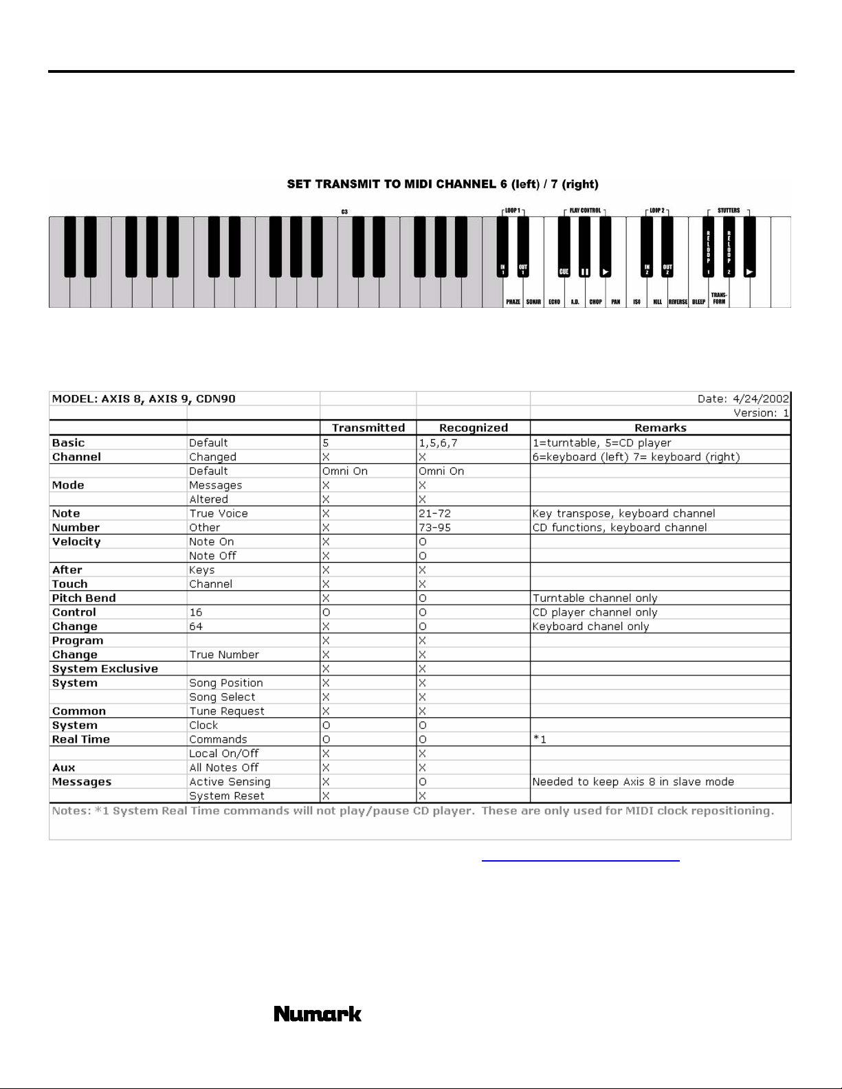
HOOKING UP A MIDI KEYBOARD: attach the MIDI output of the keyboard to the MIDI input of the CD
Player. Set your keyboard to transmit on Channel 6 to control the left side or Channel 7 to control
the right side. Add a foot pedal to the keyboard for added control. The chart below details key
reaction.
MIDI IMPLEMENTATION CHART
*note: further MIDI Specs can be found at our web site http://www.numark.com
©2000 Numark Industries - 21 - http://www.numark.com
- The Leader in DJ Technology
Page 22

CDN90
UPGRADING YOUR UNIT
This unit contains the latest software available at the time of manufacturing. Our engineering staff
will be working hard to constantly improve and offer additional f eatures in the future. The unit
software has been designed to be easily updateable by you through supplied CD updates from
Numark. To obtain the latest software version contact your local Numark Dealer or visit us on the
web at http://www.numark.com.
In order to check your unit’s software version press “PROG” followed by the “+” button.
Three sets of numbers will appear. 000 00 00 00. Your units function software will be in the
“seconds” set of numbers
For example if R1 05 34 09 appears in the display you have version 34, revision 1 of the unit code
Audio CD Programming Procedure
Downloading
1. Go to
2. Load update wave file onto a computer with CD Drive capable of burning Audio CDs.
3. If zipped, using an unzip program on your computer, unzip the file.
Burning
4. Open up your CD burning software to burn an AUDIO CD.
5. Add the software wave file to the audio program contents. It is advisable to burn the CD at the
slowest speed possible to ensure an accurate burn. If you have a disc-at-once option it should
be used.
6. You should set the program to finalize the CD.
7. Burn the disc.
Programming
8. Power up your CD player with no CD inside.
9. Place in the CD in the tray and close the drawer with the OPEN/CLOSE button. Do not close
the drawer by pressing PLAY.
10. Wait until the display indicates time remaining.
11. Press the Play button. In the effect parameter display you will see the word “test” as the time
counts down. The unit will then go through the cycle again an d indicate “busy” while the unit is
programmed.
12. At completion of the procedure the CD should eject automatically and the display will indicate
“good”.
Completion
13. Remove the CD and power the unit off for 3 seconds and then on again.
14. Recalibrate the unit following the “calibration procedure” included with the software update.
Note: CD burning is dependant upon both the recording equipment and the CD players ability to
www.numark.com and download the latest version of the unit software.
read the burned information. On rare occasions the unit may have difficulty reading the
burned CD. If the CD is ejected during the test procedure, remove the CD and try again. If
it fails again try re-burning the CD. If this doesn’t work, contact Numark service at 401295-9000 or techsupport@numark.com for a free upgrade CD.
- The Leader in DJ Technology
©2002 Numark Industries - 22 - http://www.numark.com
Page 23

SPECIFICATIONS
TECHNICAL
Disc Type Standard Compact discs (12 cm & 8 cm)
Time Display Track Elapsed, Track Remain, or Total Remain
Quantization 1 bit linear/Channel, 3 Beam Laser
Oversampling rate 8 Times
Sampling Frequency 88.2 kHz
Frequency response 20 Hz to 20 kHz
T.H.D. + NOISE Less Than 0.005%
S/N ratio (IHF-A) > 96 dB
Dynamic range > 94 dB
Output level 1.3 Volts R.M.S.
Start Time within 0.006 seconds
Pitch control range ± 6, 12, 25, 100% slider
Pitch bend ± 50% rotary and buttons ± 16%
Digital Output type 2, form 1, S/PDIF (Sony/Phillips Digital Interface Format)
GENERAL
Dimensions: Controller (mm): 482 X 132 X 42
Main Unit: 482 X 88.5 X 257
Weight: Controller: 2.3 Kg
Main Unit 4.9 Kg
Power Supply: 100/240V AC, 50/60Hz
Power Consumption: 38W
* Specifications are subject to change due to ongoing product improvements
CDN90
- The Leader in DJ Technology
©2000 Numark Industries - 23 - http://www.numark.com
Page 24

LIMITED PRODUCT WARRANTY
1. What is covered and for how long? NUMARK INDUSTRIES LLC (“NUMARK”) warrants to the original purchaser that NUMARK'S DJ Mixers, Amplifiers,
CD players, turntables, preamplifiers, beatkeepers, equalizers, microphones, headphones, and all other accessories are free from defects in material and
workmanship under normal use and service for the period commencing upon the date of purchase from an authorized NUMARK dealer and continuing for
the following period of time after that date for (1) Year.
2. What is not covered? This Limited Warranty is conditioned upon proper use of the product by the purchaser.
This Limited Warranty does not cover: (a) defects or damage resulting from accident, misuse, abuse, neglect, unusual physical or electrical stress,
modification of any part of the product, or cosmetic damage; (b) equipment that has the serial number removed or made illegible; (c) all plastic surfaces
and other externally exposed parts that are scratched or damaged due to normal use; (d) defects or damage from improper testing, operation,
maintenance, installation, adjustment, or service of the mixers; (e) crossfaders.
3. What are NUMARK'S obligations? During the applicable warranty period, NUMARK will repair or replace, at NUMARK'S sole discretion, without charge to
the purchaser, any defective component part of the mixer. To obtain service under this Limited Warranty, purchaser must first contact NUMARK and
obtain a return authorization number (“RA#”). Purchaser must then return the mixer to NUMARK in an adequate container for shipping, accompanie d by
purchaser's sales receipt or comparable proof of sale showing the date of purchase, the serial number of the product, and the seller's name and address.
To obtain an RA# and assistance on where to return the mixer, contact NUMARK customer service at 401-295 9000. Upon receipt, NUMARK will repair
or replace the defective products. NUMARK may, at NUMARK'S sole discretion, use rebuilt, reconditioned, or new parts or components when repairing
any product or replace a product with a rebuilt, reconditioned or new product. Repaired mixers will be warranted for a period equal to the remainder of the
original Limited Warranty on the original mixer or for (90) days, whichever is longer. All replaced parts, components, boards and equipment become the
property of NUMARK. If NUMARK determines that any mixer is not covered by this Limited Warranty, purchaser must pay all parts, shipping, and labor
charges for the repair or return of such mixer.
4. What are the limits on NUMARK'S liabilities? THE WARRANTIES GIVEN IN THIS LIMITED WARRANTY, TOGETHER WITH ANY IMPLIED
WARRANTIES COVERING NUMARK MIXERS, INCLUDING WITHOUT LIMITATION ANY WARRANTIES OF MERCHANTABILITY OR FITNESS FOR A
PARTICULAR PURPOSE, ARE LIMITED TO THE DURATION OF THIS LIMITED WARRANTY. EXCEPT TO THE EXTENT PROHIBITED BY
APPLICABLE LAW, NUMARK SHALL NOT BE LIABLE FOR ANY SPECIAL, INCIDENTAL, CONSEQUENTIAL, INDIRECT OR SIMILAR DAMAGES,
LOSS OF PROFITS, DAMAGES TO PURCHASER'S PROPERTY, OR INJURY TO PURCHASER OR OTHERS ARISING OUT OF THE USE, MISUSE
OR INABILITY TO USE ANY NUMARK MIXER, BREACH OF WARRANTY, OR NEGLIGENCE, INCLUDING BUT NOT LIMITED TO NUMARK'S OWN
NEGLIGENCE, EVEN IF NUMARK OR ITS AGENT HAS BEEN ADVISED OF SUCH DAMAGES, OR FOR ANY CLAIM BROUGHT AGAINST
PURCHASER BY ANY OTHER PARTY. THIS LIMITED WARRANTY IS THE COMPLETE WARRANTY FOR NUMARK'S MIXERS, AND IS GIVEN IN
LIEU OF ALL OTHER EXPRESS WARRANTIES. THIS LIMITED WARRANTY SHALL NOT EXTEND TO ANYONE OTHER THAN THE ORIGINAL
PURCHASER OF THIS PRODUCT AND STATES PURCHASER'S EXCLUSIVE REMEDY. IF ANY PORTION OF THIS LIMITED WARRANTY IS
ILLEGAL OR UNENFORCEABLE BY REASON OF ANY LAW, SUCH PARTIAL ILLEGALITY OR UNENFORCEABILTY SHALL NOT AFFECT THE
ENFORCEABILITY OF THE REMAINDER OF THIS LIMITED WARRANTY WHICH PURCHASER ACKNOWLEDGES IS AND WILL ALWAYS BE
CONSTRUED TO BE LIMITED BY ITS TERMS OR AS LIMITED AS THE LAW PERMITS.
This Limited Warranty allocates risk of product failure between purchaser and NUMARK, and NUMARK'S product pricing reflects this allocation of risk and
the limitations of liability contained in this Limited Warranty. The agents, employees, distributors, and dealers of NUMARK are not authorized to make
modifications to this Limited Warranty, or make additional warranties binding on NUMARK. Accordingly, additional statements such as dealer advertising
or presentation, whether oral or written, do not constitute warranties by NUMARK and should not be relied upon.
5. How does state law apply to this warranty? SOME STATES DO NOT ALLOW THE EXCLUSION OR LIMITATIONS OF INCIDENTAL OR
CONSEQUENTIAL DAMAGES OR HOW LONG AN IMPLIED WARRANTY LASTS, SO THE ABOVE LIMITATIONS OR EXCLUSIONS MAY NOT APPLY
TO PURCHASER.
6. This Limited Warranty gives you specific legal rights. You may also have other rights, which vary from one jurisdiction to another.
US RETURN INFORMATION
• A Return Authorization number must be obtained from Numark through the address or phone numbers below.
• A copy of the original sales receipt must also be included for the equipment to be repaired under warranty.
• The faulty equipment must be packed in its original packaging.
• One additional outer layer of packaging must be included to ensure product safety. Failures to do so may inadequately protect the equipment in
transit and, therefore, jeopardize the customer’s warranty.
• Numark will not accept COD shipments and no call tags will be issued for merchandise return.
• Numark will not return repaired merchandise to customers by priority service, unless by written request at the customer’s cost. Requests must be
submitted in writing with merchandise returned.
• The defective Numark equipment should be sent, FREIGHT PREPAID with Return Authorization number clearly printed on the outer packagi ng and
original sales receipt enclosed to:
NUMARK INDUSTRIES
Attention: Service Department
11 Helmsman Avenue
North Kingstown, RI 02852 USA
Phone: +1 (401) 295-9000
Fax: +1 (401) 295-5200
Web: www.numark.com
 Loading...