

Page 1
QUICKSTART GUIDE
ENGLISH ( 3 – 9 )
MANUAL DE INICIO RÁPIDO
ESPAÑOL ( 11 – 17 )
GUIDE D’UTILISATION RAPIDE
FRANÇAIS ( 19 – 25 )
MANUALE RAPIDO DI UTILIZZAZIONE
ITALIANO ( 27 – 33 )
KURZANLEITUNG
DEUTSCH ( 35 – 41 )
Page 2

Page 3

INTRODUCTION
Welcome to the X9 professional 3-channel mixer. Here are some of the features that you will come to love
about your new X9:
24-bit digital signal path, ensuring pristine, crystal-clear audio performance
Record and Booth RCA outputs for mix recording / monitoring
Balanced and unbalanced Master outputs for maximum connectivity with a variety of amplifiers,
speaker or home stereo systems.
2 Line inputs for connecting CD players, samplers, or other line-level devices
3 switcheable Phono / Line inputs
3-band EQ on each input channel
EQ Kill switches on each crossfader channel
2 microphone inputs
Comprehensive, easy-to-use digital effects processor
High-quality, user-replaceable crossfader
Flexible effects and crossfader assignments
Headphone output with Split / Blend cueing
We hope that the X9 serves you well for many years to come.
Sincerely,
The People of Numark
BOX CONTENTS
X9
9V-1.5A AC Power Adapter
Quickstart Guide
Safety & Warranty Information Booklet
REGISTRATION
Please go to http://www.numark.com to register your X9. Registering your product ensures that we can keep
you up-to-date with any last-minute product developments and provide you with world-class technical
support, should you run into any problems.
GROUND RULES
1. Make sure all items listed in the “Box Contents” section are included in the box.
2. READ SAFETY & WARRANTY INFORMATION BOOKLET BEFORE USING THE PRODUCT.
3. Study the connection diagram in this guide.
4. Place mixer in an appropriate position for operation.
5. Make sure all devices are turned off and all faders and gain knobs are set to “zero”
6. Connect all stereo input sources as indicated in the diagram.
7. Connect the stereo outputs to power amplifier(s), tape decks, and/or other audio sources.
8. Plug all devices into AC power.
9. Switch everything on in the following order.
• audio input sources (i.e. turntables, CD players, etc.)
• mixer
• last, any amplifiers or output devices
10. When turning off, always reverse this operation by,
• turning off amplifiers
• mixer
• last, any input devices
3
Page 4
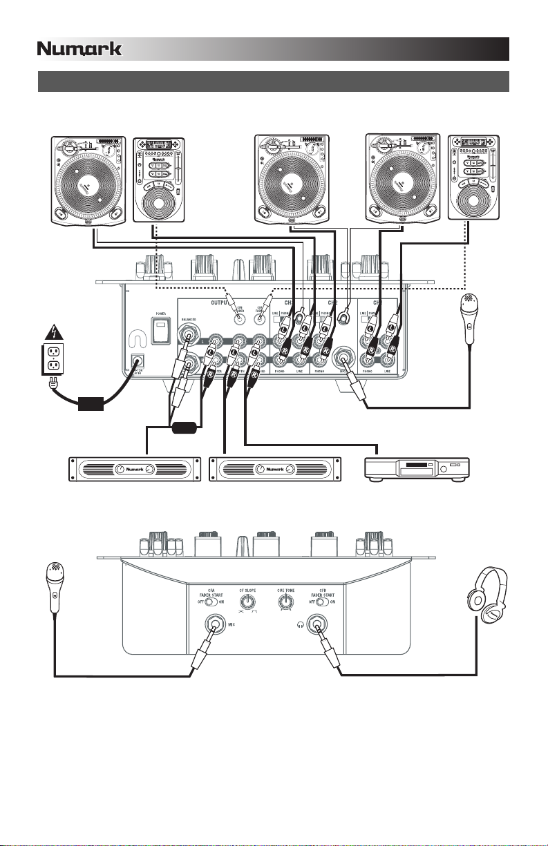
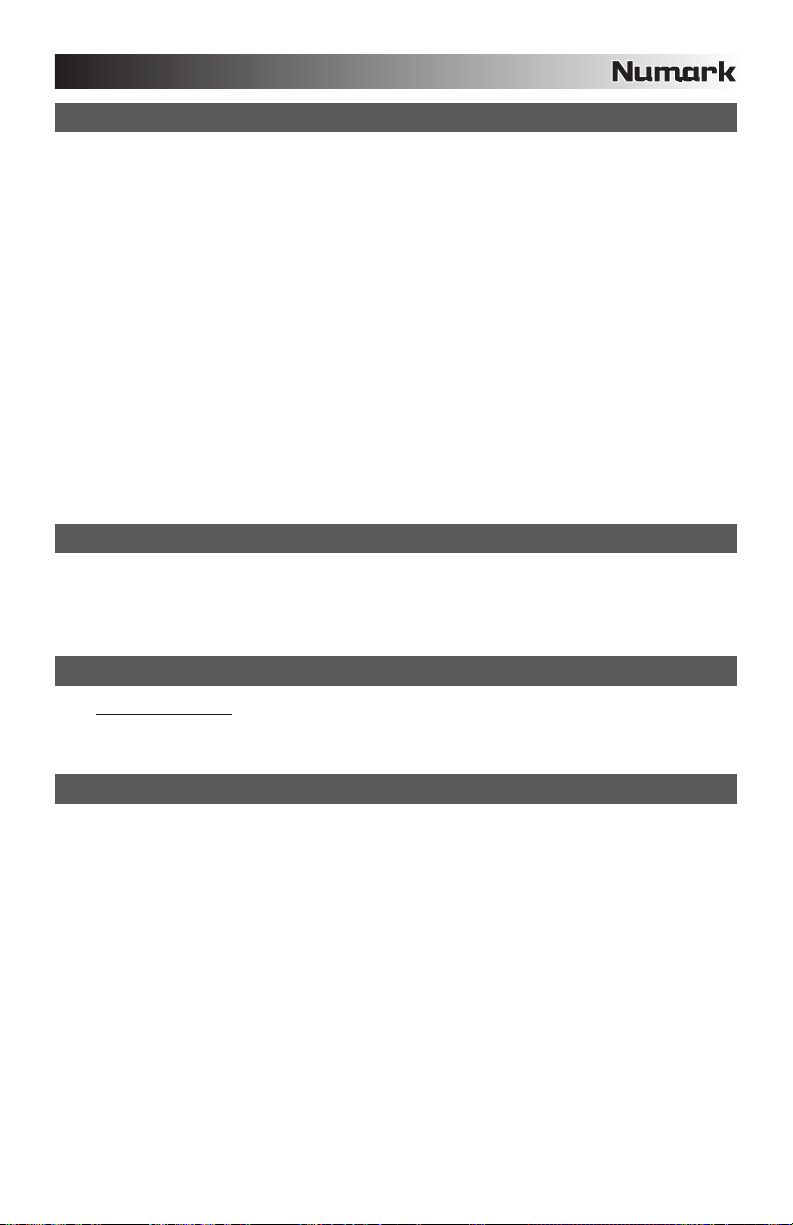
CONNECTION DIAGRAM
TURNTABLE TURNTABLE TURNTABLE
CD
PLAYER
OR
CD
PLAYER
MIC
HOUSE AMPLIFIFER
MIC
Please Note: Channels 1/2/3 can accept line-level devices (i.e. CD players, samplers, line-level turntables) in the PHONO
inputs, as long as the corresponding PHONO / LINE switch is set to LINE.
BOOTH AMPLIFIFER
CD BURNER
HEADPHONES
4
Page 5
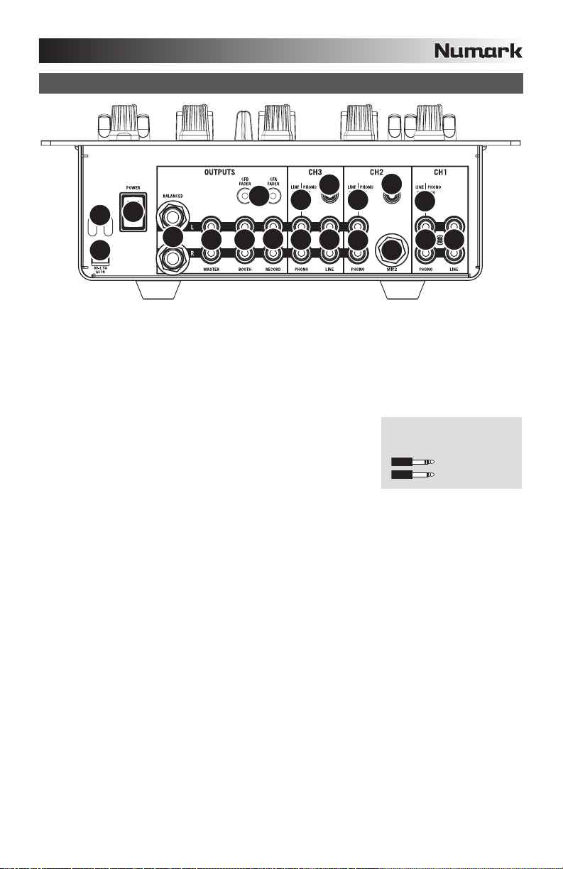
REAR PANEL FEATURES
13
3
2
4
1
AC IN – Use the included power adapter to connect the mixer to a power outlet. While the power is
1.
switched off, plug the power supply into the mixer first, then plug the power supply into a power outlet.
Please note: The mixer is designed to work with the included 9V-1.5A AC power supply only. Using
an incompatible power supply could result in damage to the unit.
2. POWER ADAPTER CABLE CLIP – To prevent accidental unplugging, secure the power adapter cable
to this clip.
3. POWER SWITCH – Turns the mixer on and off. Turn on the mixer after all input devices have been
connected and before you turn on amplifiers. Turn off amplifiers before you turn off the mixer.
4. MASTER OUTPUT (BALANCED) – Use balanced ¼” (TRS) cables
to connect this Master output to a speaker or amplifier system. The
level of this output is controlled by the Master knob on the top panel.
Tip: When possible, we recommend using these balanced outputs
for your Master audio output. Balanced outputs are better suited for
long cable runs and are less susceptible to noise and interference.
5. MASTER OUTPUT (RCA) – Use standard RCA cables to connect this Master output to a speaker or
amplifier system. The level of this output is controlled by the Master knob on the top panel.
6. BOOTH OUTPUT (RCA) – Use standard RCA cables to connect this Booth output to a booth
monitoring system. The level of this output is controlled by the Booth knob on the top panel.
7. RECORD OUTPUT (RCA) – Use standard RCA cables to connect this Record output to a recording
device, such as a CD recorder or tape deck. The level of this output is based upon pre-master levels.
8. LINE | PHONO INPUTS (RCA) – Connect your audio sources to these inputs. These inputs can
accept both line and phono-level signals. See #9 below.
9. LINE | PHONO SWITCH – Flip this switch to the appropriate position, depending on the device
connected to the Line | Phono inputs (#8). If using phono-level turntables, set this switch to “Phono” to
provide the additional amplification needed for phono-level signals. If using a line-level device, such as
a CD player or sampler, set this switch to “Line”.
10. GROUNDING TERMINAL – If using phono-level turntables with a grounding wire, be sure to connect
the grounding wire to these terminals. If you experience a low “hum” or “buzz”, this could mean that
your turntables are not grounded.
Note: Some turntables have the grounding wire built into the RCA connection and, therefore, nothing
needs to be connected to the grounding terminal.
11. LINE INPUTS – Connect line-level devices, such as CD players, samplers or audio interfaces, to these
inputs.
12. MIC 2 INPUT – If you would like to use an additional ¼” microphone on Channel 2, connect it to this
input. To route the microphone signal to the mix, you will need to flip the Channel 2 Input Selector
switch, located on the top panel, to “Mic”.
13. FADER START – If you would like to use the mixer’s fader-start to automatically start and cue music
from external devices via the mixer crossfader, connect these outputs to your fader-start compatible
device. You can use standard 1/8” stereo cables to make these connections.
5 6
7
10
9 9
8
11 11
10
9
8
8
12
How do I know if my ¼”
cables are balanced?
BALANCED
UNBALANCED
5
Page 6
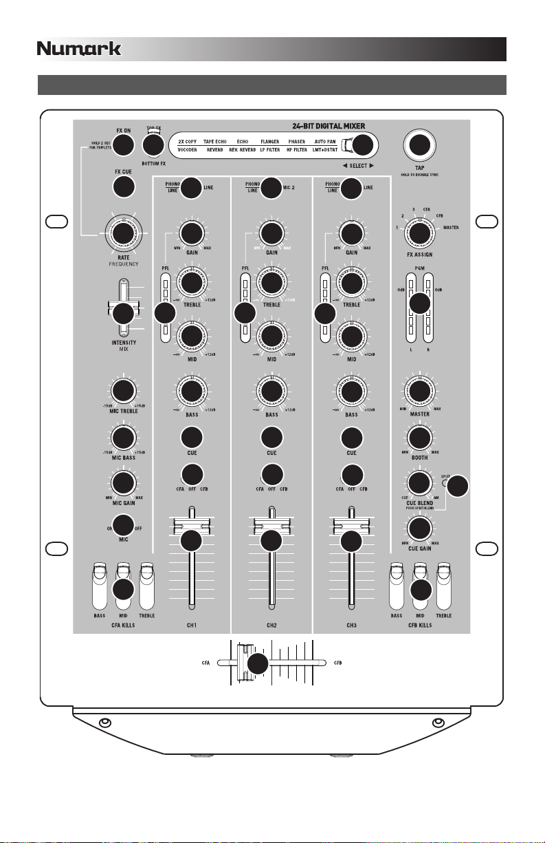
TOP PANEL FEATURES
23
28 29 27
25
26 2
24
9
19
20
21
18
1
3
4
5
6
7
1
2
3
9
4
5
6
7
1
2
22
3
9
12
4
1
6
7
10
11
14
15
13
8
8
8
17
17
16
6
Page 7

CHANNEL CONTROLS
1. INPUT SELECTOR – Selects the input source to be routed to the corresponding channel.
2. GAIN – Adjusts the channel audio pre-fader and pre-EQ gain level.
3. TREBLE – Adjusts the high (treble) frequencies of the audio playing on the corresponding channel,
4. MID – Adjusts the mid-range frequencies of the audio playing on the corresponding channel.
5. BASS – Adjusts the low (bass) frequencies of the audio playing on the corresponding channel.
6. CUE – Sends pre-fader audio to the Cue Channel for headphone monitoring.
7. CROSSFADER ASSIGN – Routes the audio playing on the corresponding channel to either side of the
crossfader (CFA/CFB), or bypasses the crossfader and sends the audio directly to the Master Mix (OFF).
8. VOLUME – Adjusts the audio level on the corresponding channel.
9. PFL – Monitors the pre-fader audio level on the corresponding channel.
MASTER CONTROLS
10. MASTER – Adjusts the Master output level.
11. BOOTH – Adjusts the Booth output level.
12. PGM – Monitors the Program (Master) mix audio level.
CUE CONTROLS
13. CUE GAIN – Adjusts the level of the headphone audio.
14. CUE BLEND – Turn to mix between Cue and Program in the Headphone channel. When all the way to the left,
only channels routed to CUE will be heard. When all the way right, only the Program mix will be heard.
Push the knob to engage Split Cue mode which sends all audio channels with the CUE Assign button engaged
to the left side of the headphones and the MASTER output to the right side of the headphones. This mode is
an excellent way to mix when booth monitoring is not available.
15. SPLIT – When lit, this LED indicates that Split Cue mode has been enabled. See Cue Blend (#14) for details
on Split Cue mode.
CROSSFADER CONTROLS
16. CROSSFADER – Blends audio between the channels assigned to the left and right side of the crossfader (see
ASSIGN KNOB below).
Note: The crossfader is user-replaceable if it should ever wear out. Simply remove the facepanel, then remove
the screws holding it in position. Replace the fader with a quality authorized replacement from your local
Numark retailer only.
17. EQ KILL SWITCHES – Eliminate the bass, mid, or high frequencies of the audio on the corresponding
crossfader channel (CFA/CFB).
MICROPHONE CONTROLS
18. MIC ON / OFF – Mutes and unmutes the microphone signal. When muted, the microphone signal will not be
routed to the Master mix.
19. MIC TREBLE – Adjusts the high (treble) frequencies of the microphone channel.
Tip: If you experience feedback when using a microphone at loud levels, try turning down the high frequencies.
20. MIC BASS – Adjusts the low (bass) frequencies of the microphone channel.
21. MIC GAIN – Adjusts the audio level of the microphone signal.
EFFECTS CONTROLS
22. FX ASSIGN – This knob selects the audio source on which the effects will be applied. You can address
individual mixer channels (1/2/3), either side of the crossfader (CFA/CFB) or you can apply the effect on the
Master mix.
23. FX ON – Turns effects processing on and off. Note that you will also have to raise the Intensity Mix control to
be able to hear the effects once they have been turned on.
24. INTENSITY MIX – Controls the amount of effected (wet) vs. non-effected (dry) sound in the mix. With the fader
down, no effected sound will be audible. With the fader up, only the effected sound will be heard.
7
Page 8
25. FX CUE – Sends the effected sound to the Cue channel for headphone monitoring. To preview effects: set the
FX ASSIGN knob to the desired source, make sure that FX ON is off (so the audience will not hear the effects
while you are previewing them) and turn on FX CUE. Make sure that the CUE BLEND control is adjusted such
that CUE can be heard. Adjust the effects controls to your desired settings. Once satisfied, turn on FX ON to
activate the effect.
26. RATE / FREQUENCY – Adjusts the rate / frequency of the selected effect.
27. TAP – In order to align tempo-synced effects with the beat, press the TAP button on the beat 3-4 times. The
beat sync often works best when tapping half the tempo. For example, try tapping just on the snare drums
(typically the “2” and “4” count).
When beat sync has been enabled, effects denoted with an asterisk (*) will have rates / frequencies related to
the tempo (see “Effects Descriptions” section). You can use the RATE / FREQUENCY knob to adjust the beatsynced rate as a multiple of the tempo (1x, 2x, 4x, etc.)
To disable beat sync and have continuous control over the rate / frequency of an effect, press and hold trhe
TAP button until it remains lit. Now the RATE / FREQUENCY knob allows you to precisely tune the rate /
frequency of an effect.
To re-enable beat sync, tap out the beat again.
28. TOP / BOTTOM FX – Selects between the top and bottom effect from the group illuminated on the display. For
example, if “TAPE ECHO / REVERB” is illuminated and this switch is in the TOP position, then the TAPE
ECHO effect is selected; if the switch is in the BOTTOM position, then the REVERB effect will be applied.
29.
SELECT – This switch selects the effects group. The selected group will illuminate as the switch is
toggled. Use the TOP / BOTTOM FX switch to select the top or bottom effect.
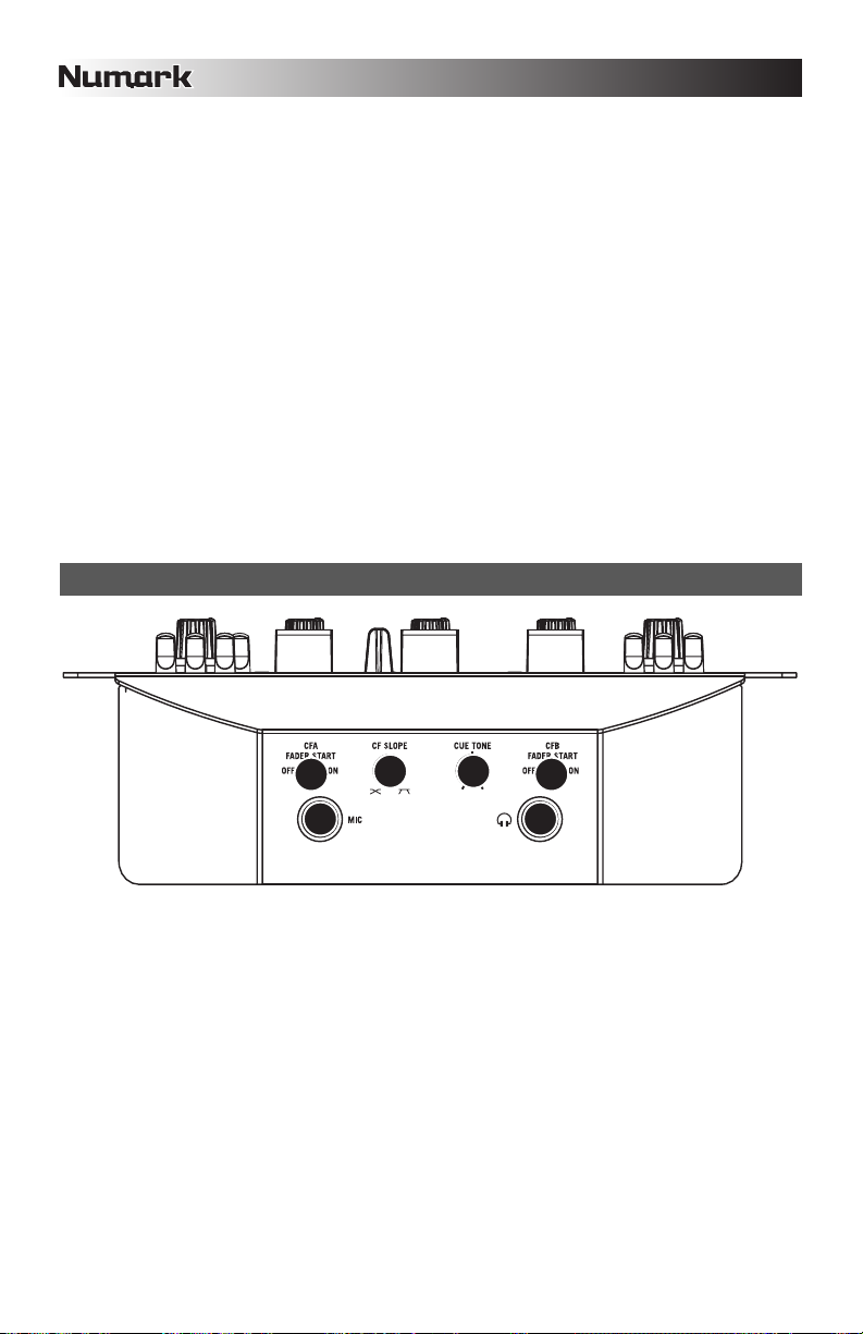
FRONT PANEL FEATURES
5 6
34
1 2
1. MIC INPUT – Connect a ¼” microphone to this input. The microphone controls are located on the top panel.
2. HEADPHONES – Connect your ¼” headphones to this output for cueing and mix monitoring. Headphone
output controls are located on the top panel.
3. CUE TONE – Adjusts the tone of the audio in the headphones. Turn to the left to attenuate high (treble)
frequencies and emphasize low (bass) frequencies. Turn to the right to emphasize high frequencies and
attenuate low frequencies.
4. CF SLOPE – Adjusts the slope of the crossfader curve. Turn to the right for a smooth fade (mixing) or turn to
the left for a sharp cut (scratching).
5. CFA FADER START – Enables or disables fader-start on the left side of the crossfader. When fader-start is
enabled, moving the crossfader from the right-most position toward the left will cause any fader-start
compatible device, connected to the CFA fader-start output on the rear panel, to start playing.
6. CFB FADER START – Enables or disables fader-start on the right side of the crossfader. When fader-start is
enabled, moving the crossfader from the left-most position toward the right will cause any fader-start
compatible device, connected to the CFB fader-start output on the rear panel, to start playing.
8
Page 9

EFFECTS DESCRIPTIONS
The X9 features a comprehensive, easy-to-use multi-effects processor. We encourage you to spend some
time becoming familiar with the operation and sound of each effect before you begin using them out at a
performance. Although effects can add a level of interest and surprise to musical material, it is often easy to
overdo it. Learn how to judiciously apply effects to your music and remember that sometimes your crowd just
wants to hear the song.
2XCOPY * – A copy of the signal is delayed by a defined time. DJs will often keep 2 copies of a record
for juggling tricks like this. Try using this effect with beat sync enabled and move the INTENSITY / MIX
fader up and down to the tempo. Now use the RATE/FREQUENCY knob to try different multiples of
the tempo.
VOCODER – A square wave vocoder, reminiscent of the robot voice sounds from the early days of
electronic music. RATE/FREQUENCY controls the pitch of the voice.
TAPE ECHO * – A much sought-after echo effect, developed in the 1960s. In beat-sync mode,
RATE/FREQUENCY controls the delay time as a multiple of the tempo (1x, 2x, 4X, etc). If beat sync
has been disabled, RATE/FREQUENCY will control delay time continuously. The INTENSITY/MIX
fader controls the input into the echo. This makes it very useful for selecting a phrase, vocal word or
beat to echo. Simply turn up the INTENSITY/MIX fader momentarily during the snippet of music you
wish to emphasize and bring it down. You’ll notice how the audio which was playing during that time
will echo away. Now try turning up the INTENSITY/MIX fader for a whole measure, then cut the music
out with the channel VOLUME fader. Let the music echo for a bit, then bring down the INTENSITY/MIX
fader and cut the music back in.
REVERB – Simulates hall reverberation. RATE/FREQUENCY controls the decay (size of room).
INTENSITY/MIX controls the wet/dry mix.
REV. REVERB – Samples the audio and plays it in reverse while adding reverb. This is a very cool
effect if you stab into the effect then immediately cut the sound using the channel VOLUME fader.
ECHO – Regular echo effect. The configuration of this echo is a little different. This time, the
INTENSITY/MIX fader controls the output of echo. When the fader is up, it will echo. Push the fader
further, and it will feedback heavily, just like the tape echo. When the fader is at the bottom, the echo
effect is cut out completely. This effect is very useful for juggling beats and emphasizing musical
phrases.
FLANGER * – Sweeping flanger effect. In beat sync mode, the RATE/FREQUENCY controls the
sweep rate as a multiple of the tempo. When beat synch is disabled, the RATE/FREQUENCY will
continuously control the sweep rate. The INTENSITY/MIX controls the intensity of the flange effect.
LP FILTER – Low-pass filter effect. INTENSITY/MIX controls the amount of filtered signal which will be
heard. RATE/FREQUENCY controls the filter’s cut-off frequency. When RATE/FREQUENCY is at its
maximum value, there will be no filtering; as you begin to turn down the knob, the effect will begin to
filter out the high (treble) frequencies of the audio.
PHASER * – Sweeping phase shifter effect. It is similar to the flanger effect, except that a flanger has
a more pronounced harmonic sound, reminiscent of a jet engine passing overhead. A phase shifter is
enharmonic, and has a “swooshing” sound. In beat sync mode, the RATE/FREQUENCY controls the
sweep rate as a multiple of the tempo. When beat sync is disabled, the RATE/FREQUENCY will
continuously control the sweep rate. The INTENSITY/MIX controls the intensity of the phase shifter
effect.
HP FILTER – High-pass filter effect. INTENSITY/MIX controls the amount of filtered signal which will
be heard. RATE/FREQUENCY controls the filter’s cut-off frequency. When RATE/FREQUENCY is at
its minimum value, there will be no filtering; as you begin to turn up the knob, the effect will begin to
filter out the low (bass) frequencies of the audio.
AUTO PAN * – Automatically pans the audio between the left and right speakers. When beat sync is
enabled, RATE/FREQUENCY controls the pan rate as a multiple of the tempo (1x, 2x, 4x, etc). If beat
sync has been disabled, RATE/FREQUENCY allows for continuous control over the pan rate.
LMT+DISTORT – Band-limited distortion effect. This effect is mainly intended to be used with a
microphone. RATE/FREQUENCY controls the distortion amount, while INTENSITY/MIX controls the
amount of distortion which will be mixed in.
(*) When beat sync has been enabled by tapping the TAP button to the beat, effects denoted with an asterisk (*) will
have rates or times which are related to the tempo. Use the RATE/FREQUENCY knob to adjust the multiple of the
tempo (1x, 2x, 4x, etc). To disable beat sync and have continuous control over rate/frequency, press and hold the TAP
button until it remains lit continuously.
9
Page 10

Page 11
INTRODUCCIÓN
Bienvenido al mezclador profesional de tres canales X9. He aquí algunas de las características que seguramente
disfrutará con su nuevo X9.
Trayecto de señal digital de 24 bits, que asegura un audio prístino y de claridad cristalina
Salidas RCA de grabación y cabina para grabar y monitorear la mezcla
Salidas maestras balanceada y no balanceada para máxima conectividad con una variedad de amplificadores
y sistemas de altavoces y estéreos hogareños.
2 entradas de línea para conectar reproductores de CD, muestreadores u otros dispositivos de nivel de línea
3 entradas fonográficas/de línea conmutables
Ecualizador de 3 bandas en cada canal de entrada
Interruptores de supresión de ecualización en cada canal de crossfader
2 entradas de micrófono
Procesador digital de efectos completo y fácil de usar
Crossfader de alta calidad, reemplazable por el usuario
Asignaciones flexibles de efectos y crossfader
Salida para auriculares con cue de división /combinación
Esperamos que el X9 le brinde un buen servicio por muchos años.
Atentamente,
La Gente de Numark
CONTENIDO DE LA CAJA
X9
Adaptador de CA de 9 V – 1.5 A
Guía de inicio rápido
Folleto de información sobre la seguridad y la garantía
REGISTRO
Visite http://www.numark.com y registre su X9. El registro de su producto asegura que podamos mantenerle
actualizado con los desarrollos de productos de último momento y brindarle apoyo técnico de categoría mundial en
caso de que tenga algún problema.
REGLAS BÁSICAS
1. Asegúrese de que todos los artículos indicados en “Contenido de la caja" estén incluidos en la caja.
2. LEA EL FOLLETO DE INFORMACIÓN SOBRE LA SEGURIDAD Y LA GARANTÍA ANTES DE UTILIZAR EL
PRODUCTO.
3. Estudie el diagrama de conexión incluido en esta guía.
4. Coloque el mezclador en una posición adecuada para su funcionamiento.
5. Asegúrese que todos los dispositivos estén apagados y que todos los faders y perillas de ganancia estén en
posición «cero».
6. Conecte todas las fuentes de entrada estéreo como se indica en el diagrama.
7. Conecte las salidas estéreo a los amplificadores de potencia, bandejas de cinta magnética y/o otras fuentes de
audio.
8. Enchufe todos los dispositivos al suministro de corriente alterna.
9. Encienda todo en el siguiente orden:
• fuentes de entrada de audio (por ejemplo, giradiscos, reproductores de CD, etc.)
• el mezclador
• por último, cualquier amplificador o dispositivo de salida
10. Al apagar, realice siempre esta operación en sentido inverso:
• apague los amplificadores
• el mezclador
• por último, cualquier dispositivo de entrada
11
Page 12
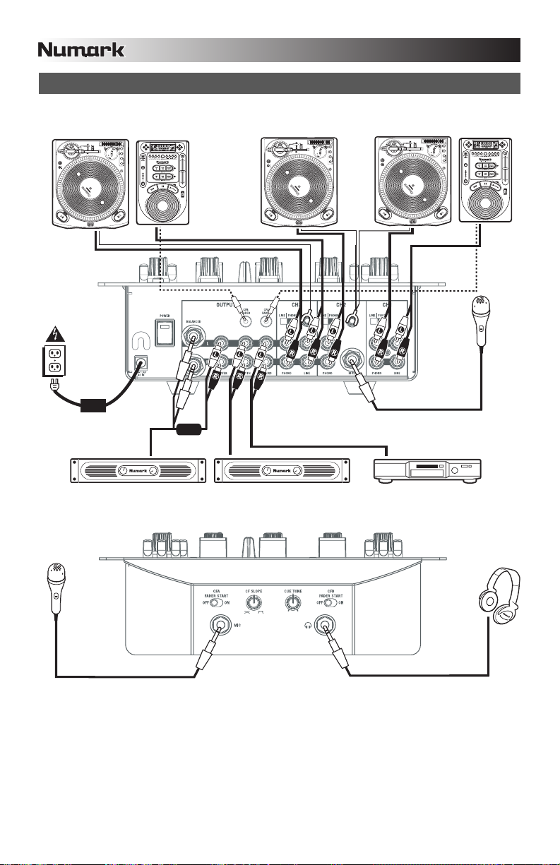
DIAGRAMA DE CONEXIÓN
GIRADISCOS
REPRODUCTOR
DE CD
OR
GIRADISCOS
GIRADISCOS
REPRODUCTOR
DE CD
MICRÓFONO
AMPLIFICADOR DE AUDITORIO
MICRÓFONO
Para tener en cuenta: Los canales 1/2/3 pueden aceptar dispositivos de nivel de línea (por ej. reproductores de CD,
muestreadores, giradiscos de nivel de línea) en las entradas PHONO, siempre que el conmutador PHONO / LINE
AMPLIFICADOR DE CABINA
correspondiente esté colocado en LINE.
QUEMADOR
DE CD
12
AURICULARES
Page 13

CARACTERÍSTICAS DEL PANEL TRASERO
1. ENTRADA DE CA - Use
el adaptador de
alimentación incluido
para conectar el
mezclador a un
tomacorriente
alimentado. Mientras
está desconectada la
alimentación eléctrica,
enchufe la fuente de
alimentación al
mezclador primero, y
luego al tomacorriente.
Para tener en cuenta: El mezclador está diseñado para funcionar con la fuente de alimentación de CA de 9 V-
1.5 únicamente . Si usa una fuente de alimentación incompatible se puede dañar la unidad.
2. PRESILLA DEL CABLE DEL ADAPTADOR DE ALIMENTACIÓN – Para evitar la desconexión accidental,
sujete el cable del adaptador de alimentación a esta presilla.
3. INTERRUPTOR DE ENCENDIDO – Enciende y apaga el mezclador. Encienda el mezclador después de
desconectar todos los dispositivos de entrada y antes de encender los amplificadores. Apague los
amplificadores antes de apagar el mezclador.
4. SALIDA MAESTRA (BALANCEADA) – Use cables de ¼”
balanceados (TRS) para conectar esta salida maestra a un sistema
de altavoces o amplificador. El nivel de esta salida se controla con
la perilla MASTER del panel superior.
Consejo: Recomendamos usar estas salidas balanceadas, cuando
sea posible, para la salida de audio maestra. Las salidas
balanceadas funcionan mejor con tramos largos de cables y son
menos susceptibles al ruido y la interferencia.
5. SALIDA MAESTRA (RCA) – Use cables RCA estándar para conectar esta salida maestra a un sistema de
altavoces o amplificador. El nivel de esta salida se controla con la perilla MASTER del panel superior.
6. SALIDA PARA CABINA (RCA) – Use cables RCA estándar para conectar esta salida a un sistema de
monitoreo de cabina. El nivel de esta salida se controla con la perilla BOOTH del panel superior.
7. SALIDA PARA GRABACIÓN (RCA) – Use cables RCA estándar para conectar esta salida a un dispositivo de
grabación, tal como un grabador de CD o bandeja de cinta. El nivel de esta salida se basa en los niveles premaster.
8. ENTRADAS DE LÍNEA | FONOGRÁFICA (RCA) – Conecte sus fuentes de audio a estas entradas. Estas
entradas pueden aceptar señales de nivel de línea y fonográfico. Vea el Nº 9 a continuación.
9. INTERRUPTOR DE ENTRADA DE LÍNEA | FONOGRÁFICA – Coloque este conmutador en la posición
apropiada, en función del dispositivo conectado a las entradas Line | Phono (Nº 8). Si usa giradiscos de nivel
fonográfico, coloque este conmutador en “Phono” para proporcionar la amplificación adicional necesaria para
las señales de este nivel. Si usa un dispositivo de nivel de línea, tal como un reproductor de CD o
muestreador, coloque este conmutador en “Line”.
10. TERMINAL DE TIERRA – Si usa giradiscos de nivel fonográfico con cable de conexión a tierra, asegúrese de
conectar dicho cable a estos terminales. Si se experimenta un zumbido grave, puede significar que sus
giradiscos no están conectados a tierra.
Nota: Algunos giradiscos tienen el cable de conexión a tierra incorporado a la conexión RCA y, por lo tanto, no
es necesario conectar nada al terminal de tierra.
11. ENTRADAS DE LÍNEA – Estas entradas se usan para conectar dispositivos de nivel de línea, tales como
reproductores de CD, muestreadores o interfaces de audio.
12. ENTRADA DE MICRÓFONO 2 – Si desea usar un micrófono de ¼” adicional en el canal 2, conéctelo a esta
entrada. Para aplicar la señal de micrófono a la mezcla, debe colocar el conmutador selector de entrada del
canal 2, ubicado en el panel superior, en “Mic”.
13. FADER START – Si desea usar el fader-start del mezclador para iniciar y buscar automáticamente el punto
inicial de música de dispositivos externos a través del crossfader del mismo, conecte estas salidas a su
dispositivo compatible con fader-start. Puede usar cables estéreo estándar 1/8” para efectuar estas
conexiones.
3
2
1
4
13
5 6
10
9 9
7
8
11 11
¿Cómo sé si mis cables de ¼”
son balanceados?
10
9
8
8
12
BALANCEADO
NO BALANCEADO
13
Page 14
CARACTERÍSTICAS DEL PANEL SUPERIOR
23
28 29 27
25
26 2
24
9
19
20
21
18
17
1
3
4
5
6
7
1
2
3
9
4
5
6
7
1
2
22
3
9
12
4
1
6
7
10
11
14
15
13
8
8
8
17
16
14
Page 15

CONTROLES DE CANALES
1. SELECTOR DE ENTRADAS - Permite seleccionar la fuente de entrada que se aplica al canal
correspondiente.
2. GANANCIA - Ajusta el nivel de ganancia preecualización y pre-fader del audio del canal.
3. TREBLE – Ajusta las altas frecuencias (agudos) del audio que se reproduce en el canal correspondiente.
4. MEDIOS – Ajusta las frecuencias medias del audio que se reproduce en el canal correspondiente.
5. GRAVES – Ajusta las bajas frecuencias (graves) del audio que se reproduce en el canal correspondiente.
6. CUE – Envía el audio pre-fader al canal de Cue para monitoreo con los auriculares.
7. ASIGNACIÓN DE CROSSFADER – Aplica el audio que se reproduce en el canal correspondiente a
cualquiera de los lados del crossfader (CFA/CFB), o puentea el crossfader y envía el audio directamente a la
mezcla maestra (OFF).
8. VOLUMEN – Ajusta el nivel de audio en el canal correspondiente.
9. PFL – Monitorea el nivel de audio pre-fader en el canal correspondiente.
CONTROLES DE LA SALIDA MAESTRA
10. MAESTRA – Ajusta el nivel de la salida maestra.
11. CABINA – Ajusta el nivel de la salida para cabina.
12. PGM – Monitorea el nivel de audio del programa (maestro).
CONTROLES DE CUE
13. GANANCIA DE CUE – Ajusta el nivel del audio para auriculares.
14. COMBINACIÓN DE CUE – Gírelo para mezclar cue y programa en el canal de auriculares. Cuando está en el
extremo izquierdo, sólo se oyen los canales aplicados a CUE. Cuando se gira totalmente a la derecha, se oye
sólo la mezcla del programa.
Presione la perilla para activar el modo de cue dividido que envía todos los canales de audio con el botón de
asignación de “cue” activado al lado izquierdo de los auriculares y la salida maestra al lado derecho de los
mismos. Este modo es una manera excelente de mezclar cuando el monitoreo de la cabina no está
disponible.
15. DIVISIÓN – Cuando se enciende, este LED indica que se activó el modo Split Cue (cue dividido). Consulte los
detalles del modo de cue dividido en Combinación de cue (Nº 14).
CONTROLES DEL CROSSFADER
16. CROSSFADER - Combina el audio entre los canales asignados a los lados izquierdo y derecho del crossfader
(consulte PERILLA DE ASIGNACIÓN más abajo).
Nota: El usuario puede reemplazar el crossfader en caso de que se desgaste. Simplemente, retire el panel
frontal y luego los tornillos que lo mantienen sujeto. Cambie el fader por un repuesto de calidad autorizado por
su vendedor de Numark más cercano.
17. INTERRUPTORES DE SUPRESIÓN DE ECUALIZACIÓN – Eliminan las frecuencias bajas, medias o altas del
canal de crossfader correspondiente (CFA/CFB).
CONTROLES DE MICRÓFONO
18. MICRÓFONO SÍ/NO – Silencia y anula el silenciamiento de la señal de micrófono. Cuando está silenciada, la
señal de micrófono no se aplica a la mezcla maestra.
19. AGUDOS DE MICRÓFONO – Ajusta las altas frecuencias (agudos) del canal de micrófono.
Consejo: Si experimenta realimentación cuando usa un micrófono con niveles altos, pruebe disminuyendo las
altas frecuencias.
20. GRAVES DE MICRÓFONO – Ajusta las bajas frecuencias (graves) del canal de micrófono.
21. GANANCIA DE MICRÓFONO – Ajusta el nivel de audio de la señal de micrófono.
CONTROLES DE EFECTOS
22. ASIGNACIÓN DE EFECTOS – Esta perilla selecciona la fuente de audio sobre la que se aplican los efectos.
Puede direccionarlo a los canales individuales del mezclador (1/2/3), a cualquiera de los lados del crossfader
(CFA/CFB) o aplicar el efecto a la mezcla maestra.
23. EFECTOS SÍ/NO - Hace que se active y desactive el procesamiento de efectos. Tenga en cuenta que debe
elevar también el control Intensity Mix para poder oír los efectos una vez que se hayan activado.
24. MEZCLA DE INTENSIDADES – Controla la relación entre la magnitud del sonido con efectos (wet) y el sonido
sin efectos (dry) en la mezcla. Con el fader hacia abajo, es audible el sonido sin efectos. Con el fader hacia
arriba, sólo es audible el sonido con efectos.
15
Page 16

25. CUE DE EFECTOS – Envía el sonido con efectos al canal de Cue para monitoreo con los auriculares. Para
oír previamente los efectos: coloque la perilla FX ASSIGN en la fuente deseada, asegúrese de que FX ON
esté apagado (para que la audiencia no oiga los efectos mientras usted los oye previamente) y encienda FX
CUE. Asegúrese que el control CUE BLEND esté ajustado de modo que pueda oírse el CUE. Ajuste los
controles de efectos a los valores que desee. Una vez satisfecho, encienda FX ON para activar el efecto.
26. CADENCIA / FRECUENCIA – Ajusta la cadencia / frecuencia del efecto seleccionado.
27. TAP – A fin de alinear los efectos sincronizados con el tempo con el beat, pulse el botón TAP en el beat 3 ó 4
veces. El sincronismo con el beat con frecuencia funciona mejor cuando se golpea a la mitad del tempo. Por
ejemplo, pruebe golpeando sólo en los snare drums (habitualmente el “2” y “4” de la cuenta).
Cuando se haya activado el sincronismo con el beat, los efectos indicados con un asterisco (*) tendrán
cadencias / frecuencias relacionadas con el tempo (consulte la sección “Descripciones de los efectos”). Puede
usar la perilla RATE / FREQUENCY para ajustar la cadencia sincronizada con el beat como múltiplo del tempo
(1x, 2x, 4x, etc.)
Para desactivar el sincronismo con el beat y tener control continuo sobre la cadencia / frecuencia de un efecto,
pulse y retenga el botón TAP hasta que quede encendido. Ahora la perilla RATE / FREQUENCY le permite
afinar con precisión la cadencia / frecuencia de un efecto.
Para volver a activar el sincronismo con el beat, golpee en el beat nuevamente.
28. EFECTO DE ARRIBA / ABAJO - Este conmutador selecciona el efecto de la parte superior e inferior del
grupo iluminado en la pantalla. Por ejemplo, si se ilumina “TAPE ECHO / REVERB” y el conmutador está en la
posición TOP (Arriba), se selecciona el efecto TAPE ECHO; si está en la posición BOTTOM (Abajo), se
selecciona el efecto REVERB.
29. SELECCIÓN – Este conmutador selecciona el grupo de efectos. El grupo seleccionado se ilumina a
medida que se acciona el conmutador. Use el conmutador TOP / BOTTOM FX para seleccionar el efecto de
arriba o abajo.
CARACTERÍSTICAS DEL PANEL FRONTAL
5 6
34
1 2
1. ENTRADA DE MICRÓFONO – Conecte un micrófono de 1/4” a esta entrada. Los controles de micrófono se
encuentran en el panel superior.
2. AURICULARES – Conecte sus auriculares de ¼” a esta salida para búsqueda de punto inicial (cue) y
monitoreo de la mezcla. Los controles de la salida para auriculares se encuentran en el panel superior.
3. TONO DE CUE – Ajusta el tono del audio de los auriculares. Gire este control a la izquierda para atenuar los
agudos (altas frecuencias) y resaltar los graves (bajas frecuencias). Gírelo a la derecha para resaltar los
agudos (altas frecuencias) y atenuar los graves (bajas frecuencias).
4. PENDIENTE DE CROSSFADER – Ajusta la pendiente de la curva del crossfader. Gire este control a la
derecha para una fusión suave (mezcla) o a la izquierda para un corte abrupto (rayado).
5. FADER START DE CFA – Activa o desactiva el fader-start del lado izquierdo del crossfader. Cuando el fader-
start está activado, al mover el crossfader desde el extremo derecho hacia la izquierda, hace que cualquier
dispositivo compatible con fader-start conectado a la salida de fader-start de CFA del panel trasero comience a
reproducir.
6. FADER START DE CFB – Activa o desactiva el fader-start del lado derecho del crossfader. Cuando el fader-
start está activado, al mover el crossfader desde el extremo izquierdo hacia la derecha, hace que cualquier
dispositivo compatible con fader-start conectado a la salida de fader-start de CFB del panel trasero comience a
reproducir.
16
Page 17

DESCRIPCIONES DE LOS EFECTOS
El X9 cuenta con un procesador digital de efectos completo y fácil de usar. Recomendamos que dedique algún
tiempo a familiarizarse con la operación y el sonido de cada efecto antes de usarlo en una sesión. Si bien los
efectos pueden agregar un nivel de interés y sorpresa al material musical, con frecuencia es fácil sobrepasarse.
Aprenda a aplicar los efectos a su música con criterio y recuerde que su audiencia a veces sólo desea escuchar el
tema.
2XCOPY * – Una copia de la señal se retarda un tiempo definido. Los DJ guardan con frecuencia 2 copias de
una grabación para hacer trucos como éste. Pruebe usando este efecto con el sincronismo con el beat
activado y mueva el fader INTENSITY / MIX hacia arriba y abajo según el tempo. Use también la perilla
RATE/FREQUENCY para probar distintos múltiplos del tempo.
VOCODER – Codificador de voz de onda cuadrada, una reminiscencia de los sonidos de voz de robot de los
primeros tiempos de la música electrónica. RATE/FREQUENCY controla el pitch de la voz.
TAPE ECHO * – Efecto de eco muy buscado, desarrollado en los años 60. En el modo de sincronismo con el
beat, RATE / FREQUENCY controla el tiempo de retardo como múltiplo del tempo (1x, 2x, 4x, etc.) Si el
sincronismo con el beat está desactivado, RATE/FREQUENCY controla el tiempo de retardo continuamente.
El fader INTENSITY/MIX controla la entrada al eco. Esto lo hace muy útil para seleccionar una frase, palabra
vocal o beat para el eco. Simplemente, mueva momentáneamente hacia arriba el fader INTENSITY/MIX
durante el trazo de música que desea enfatizar y luego muévalo hacia abajo. Notará que el audio que se
estaba reproduciendo durante ese momento se escuchará con eco. Ahora pruebe mover hacia arriba el fader
INTENSITY/MIX por una medida completa y luego corte la música con el fader VOLUME del canal. Permita
que la música haga eco un momento y luego lleve hacia abajo el fader INTENSITY/MIX y vuelva a introducir la
música.
REVERB – Simula la reverberación de la sala de conciertos. RATE/FREQUENCY controla el decaimiento
(tamaño de la sala). INTENSITY/MIX controla la mezcla wet/dry (música con y sin efectos).
REV. REVERB – Muestrea el audio y la reproduce en reversa mientras agrega reverberación. Éste es un
efecto excelente si lo activa y corta el sonido inmediatamente usando el fader VOLUME del canal.
ECHO - Efecto de eco normal. La configuración de este eco es ligeramente diferente. Esta vez, el fader
INTENSITY/MIX controla la salida del eco. Cuando el fader está hacia arriba, el eco está activo. Lleve el fader
más allá y sufrirá una gran realimentación, igual que el eco de cinta. Cuando el fader está hacia abajo, el
efecto eco se anula completamente. Este efecto es muy útil para hacer malabarismos con los beats y dar
énfasis a las frases musicales.
FLANGER*: Barrido del efecto flanger. En modo de sincronización con el beat, la perilla RATE/FREQUENCY
controla la frecuencia de barrido como múltiplo del tiempo. Cuando se desactiva la sincronización con el beat,
esta perilla controla continuamente la frecuencia de barrido. El fader INTENSITY/MIX controla la intensidad del
efecto flanger.
LP FILTER – Efecto de filtro pasabajos. INTENSITY/MIX controla la magnitud de señal filtrada que se oye.
RATE/FREQUENCY controla la frecuencia de corte del filtro. Cuando RATE/FREQUENCY está en su valor
máximo, no hay filtrado y, cuando se comienza a mover la perilla hacia abajo, el efecto comienza a filtrar
eliminando las altas frecuencias (agudos) del audio.
PHASER* - Barrido del efecto de desfasador. Es similar al efecto flanger, salvo que el flanger tiene un sonido
armónico mas pronunciado, que recuerda al motor de un jet que pasa por encima nuestro. El desfasador es
enarmónico y tiene un sonido más “de silbido”. En modo de sincronización con el beat, la perilla
RATE/FREQUENCY controla la frecuencia de barrido como múltiplo del tempo. Cuando se desactiva la
sincronización con el beat, esta perilla controla de forma continua la frecuencia de barrido. El fader
INTENSITY/MIX controla la intensidad del efecto de desfasador.
HP FILTER – Efecto de filtro pasaaltos. INTENSITY/MIX controla la magnitud de señal filtrada que se oye.
RATE/FREQUENCY controla la frecuencia de corte del filtro. Cuando RATE/FREQUENCY está en su valor
mínimo, no hay filtrado, cuando se comienza a mover la perilla hacia arriba, el efecto comienza a filtrar
eliminando las bajas frecuencias (graves) del audio.
AUTO PAN * – Balancea automáticamente el audio entre los altavoces izquierdo y derecho. Cuando el modo
de sincronismo con el beat está activado, RATE / FREQUENCY controla la cadencia de balance como múltiplo
del tempo (1x, 2x, 4x, etc.) Si el sincronismo con el beat está desactivado, RATE/FREQUENCY permite el
control continuo de la cadencia del balance.
LMT+DISTORT – Efecto de distorsión con limitación de banda. Este efecto está diseñado para usar
principalmente con un micrófono. RATE/FREQUENCY controla la magnitud de la distorsión, mientras que
INTENSITY/MIX controla la cantidad de distorsión que se mezcla.
(*) Cuando se activa el modo de sincronismo con el beat pulsando el botón TAP al ritmo del beat, los efectos marcados
con un asterisco (*) tendrán cadencias o tiempos que están relacionados con el tempo. Utilice la perilla
RATE/FREQUENCY para ajustar los múltiplos del tempo (1x, 2x, 4x, etc). Para desactivar el sincronismo con el beat y
tener control continuo sobre la cadencia / frecuencia, pulse y retenga el botón TAP hasta que quede encendido
continuamente.
17
Page 18

Page 19

INTRODUCTION
Voici la console de mixage à 3 canaux X9. Voici quelques-uns des caractéristiques que vous apprécierez de la
nouvelle console de mixage X9 :
Cheminement numérique 24 bits, assurant une reproduction audio de grande qualité.
Sorties RCA enregistrement et cabine pour l’enregistrement des mix et la pré-écoute.
Sorties maîtres symétriques et asymétriques permettant une meilleure connectivité avec une large gamme
d’amplificateurs, enceintes et systèmes stéréo.
2 entrées à niveau ligne permettent de brancher des lecteurs de disques compacts, échantillonneurs ou autres
appareils à niveau ligne.
Entrées phono/ligne commutables.
Égalisation 3 bandes sur chaque canal d’entrée.
Coupure d’égalisation sur chaque canal crossfader.
2 entrées microphone.
Processeur d’effets numérique facile à utiliser
Crossfader remplaçable de grande qualité
Flexibilité des assignations des effets et du crossfader
Sortie casque d’écoute dotée de la fonction de répartition/mixage du casque d'écoute (Split/Blend)
Nous espérons que la console de mixage X9 vous servira bien pendant plusieurs années.
Cordialement,
Toute l’équipe de Numark
CONTENUE DE LA BOÎTE
X9
Adaptateur CA 9 V 1,5 A
Guide d'utilisation simplifié
Le livret des consignes de sécurité et des informations concernant la garantie.
ENREGISTREMENT
Veuillez visiter le site internet http://www.numark.com pour enregistrer votre nouvelle console X9.L'enregistrement
des produits vous permet d'être informé sur les toutes dernières nouveautés concernant les produits et de vous offrir
un soutien technique de niveau international, si vous en aviez besoin.
RÈGLES DE BASE
1. Assurez-vous que tous les articles énumérés dans le contenu de la boîte de ce guide sont inclus dans la boîte.
2. VEUILLEZ LIRE LE LIVRET DES CONSIGNES DE SÉCURITÉ ET DES INFORMATIONS SUR LA
GARANTIE AVANT D'UTILISER LE PRODUIT.
3. Examinez le schéma de connexion de ce guide.
4. Placez la console de mixage en position de fonctionnement.
5. Assurez-vous que tous les appareils sont hors tension et que tous les atténuateurs et le gain sont réglés à
« zéro ».
6. Connectez toutes les sources d'entrées stéréo tel qu'indiqué sur le schéma.
7. Branchez toutes les sorties aux amplificateurs de puissance, aux lecteurs de cassette et aux sources audio.
8. Branchez tous les appareils à une prise de courant alternatif (AC).
9. Mettre tous les appareils sous tension dans l'ordre suivant.
• sources d'entrée audio (c.-à-d.tourne-disques, lecteurs de disques compacts, etc.)
• Consoles de mixage
• en dernier, tous amplificateurs ou appareils de sortie
10. Pour mettre hors tension, toujours inverser l'opération :
• Éteindre les amplificateurs
• Consoles de mixage
• En dernier, tous les appareils d'entrée
19
Page 20

É
SCHÉMA DE CONNEXION
TABLE
TOURNANTE
LECTEUR DE
DISQUES
OR
TABLE
TOURNANTE
TABLE
TOURNANTE
LECTEUR DE
DISQUES
MICRO
AMPLIFICATEUR MAISON
MICRO
Veuillez noter : Les canaux 1/2/3 permettent de brancher des appareils à niveau ligne tels que lecteurs de disques compacts,
échantillonneurs et tables tournantes dans les entrées PHONO si le commutateur PHON/LINE est en position LINE.
AMPLIFICATEUR CABINE
GRAVEUR CD
CASQUE D'
20
COUTE
Page 21

CARACTÉRISTIQUES DU PANNEAU ARRIÈRE
13
3
2
4
1
1. AC IN – Branchez l’adaptateur d’alimentation inclus pour brancher la console dans une prise d’alimentation
murale. Lorsque la console de mixage est hors tension, branchez le câble d'alimentation dans la console, puis
dans la prise de courant.
Veuillez noter : Cette console de mixage est conçue pour fonctionner avec le câble d'alimentation 9 V 1,5 A
c.c.fourni. L’utilisation d’un autre câble pourrait endommager l’appareil.
2. CLIP – Utilisez ce clip pour fixer le câble afin de ne pas le débrancher accidentellement.
3. L'interrupteur d'alimentation (POWER) – Met l’appareil sous et hors tension. Branchez la console après
avoir branché tous les appareils et avant de mettre les amplificateurs sous tension. Mettre les amplificateurs
hors tension avant de mettre la console de mixage hors tension.
4. MASTER (Symétrique) – Utilisez des câbles symétriques de ¼ po (TRS)
afin de brancher cette sortie à un haut-parleur ou à un système de
sonorisation. Le niveau du signal de cette sortie est commandé par le
bouton Master du panneau supérieur.
CONSEIL : Lorsque cela est possible, nous vous recommandons
d’utiliser ces sorties symétriques pour la sortie audio Master. Les sorties
symétriques sont meilleures pour les longs câblages et sont moins
susceptibles au bruit et à l’interférence.
5. MASTER (RCA) – Utilisez des câbles RCA standards afin de brancher cette sortie à un haut-parleur ou à un
système de sonorisation. Le niveau du signal de cette sortie est commandé par le bouton Master du panneau
supérieur.
6. BOOTH (RCA) – Utilisez des câbles RCA standards afin de brancher cette sortie à système de pré-écoute. Le
niveau du signal de cette sortie est commandé par le bouton Booth du panneau supérieur.
7. RECORD (RCA) – Utilisez des câbles RCA standards afin de brancher cette sortie à un appareil
d’enregistrement tel qu’un lecteur de cassettes ou un graveur de CD. Le niveau de la sortie dépend des
niveaux prémastérisation.
8. LINE | PHONO (RCA) – Branchez ces entrées aux sources audio. Ces entrées peuvent accepter les signaux
phono et à niveau ligne. Voir no.9 ci-dessous.
9. LINE | PHONO SWITCH – Mettre ce sélecteur à la position appropriée, selon l’appareil branché aux entrées
Line | Phono (8). Si vous utilisez des tables tournantes phono à niveau ligne, réglez ce sélecteur à « Phono »
afin d’ajouter plus d’amplification pour les signaux phono à niveau ligne. Pour brancher un appareil à niveau de
ligne, tel qu’un lecteur CD ou un échantillonneur, réglez le sélecteur LINE/PHONO à la position LINE.
10. BORNE DE MISE À LA TERRE – Si vous utilisez des tables tournantes avec fils de mise à la terre, assurez-
vous de brancher le fils à cette borne. S’il y a un ronflement ou du bruit, il se pourrait que vos tables tournantes
ne soient pas mises à la terre.
Remarque : Certains des tourne-disques fabriqués récemment sont dotés d'un fil de mise à la terre intégrée à
la connexion RCA, et donc, n'ont pas besoin doit être relié à la borne de mise à la terre.
11. ENTRÉES LINE – Ces entrées permettent de brancher des appareils à niveau ligne tels que lecteurs de
disques compacts, échantillonneurs ou autres interfaces audio.
12. ENTRÉE MIC 2 – Utilisez cette entrée afin de brancher un microphone ¼ po supplémentaire sur le canal 2.
Pour acheminer le signal du microphone au mix, vous devez mettre le sélecteur d’entrée du canal 2, situé sur
le panneau supérieur à « Mic ».
13. FADER START – Si vous désirez utiliser la fonction fader start de la console afin qu’elle lance et arrête la
musique provenant d’autres appareils à partir du crossfader de la console, branchez ces sorties aux appareils
compatibles avec cette fonction. Vous pouvez utiliser des câbles stéréo standards de 1/8 po pour faire ces
raccordements.
5 6
7
10
9 9
8
11 11
10
9
8
8
12
Comment savoir si les câbles
de ¼ po sont symétriques?
SYMÉTRIQUE
ASYMÉTRIQUE
21
Page 22

CARACTÉRISTIQUES DU PANNEAU ARRIÈRE
23
28 29 27
25
26 2
24
9
19
20
21
18
1
3
4
5
6
7
1
2
3
9
4
5
6
7
1
2
22
3
9
12
4
1
6
7
10
11
14
15
13
8
8
8
17
17
16
22
Page 23

COMMANDES DES CANAUX
1. SÉLECTEUR D’ENTRÉE – Ce réglage permet de sélectionner la source d’entrée qui est acheminée au canal.
2. GAIN – Permet d'ajuster le niveau du signal audio pré-atténuateur et pré-égalisation.
3. TREBLE – Adjusts the high (treble) frequencies of the audio playing on the corresponding channel.
4. MID – Permet d'ajuster le niveau des fréquences moyennes de l’audio du canal correspondant.
5. BASS – Permet d'ajuster le niveau des basses fréquences de l’audio du canal correspondant.
6. CUE – Achemine les niveaux de l’audio pré-atténuateur à la pré-écoute casque.
7. ASSIGNATION DU CROSSFADER – Achemine l’audio du canal correspondant à l’une des extrémités du
crossfader (CFA/CFB), ou permet de contourner le crossfader et d’acheminer l’audio directement au Master
Mix (OFF).
8. VOLUME – Permet d'ajuster le niveau de l’audio du canal correspondant.
9. PFL – Permet d'ajuster le niveau de pré-atténuation de l’audio du canal correspondant.
COMMANDES PRINCIPALES
10. MASTER – Permet d’ajuster le niveau de l’audio de la sortie principale.
11. BOOTH – Permet d’ajuster le niveau de l’audio de la sortie Booth.
12. PGM – Permet de contrôler le niveau du programme (Master mix).
COMMANDE DE PRÉ-ÉCOUTE
13. CUE GAIN – Permet d’ajuster les niveaux de la sortie du casque d'écoute.
14. CUE BLEND – Permet d’ajuster le mixe entre la pré-écoute et le programme du canal du casque d’écoute.
Lorsqu'il est déplacé à l’extrémité gauche, seul le signal acheminé au casque d’écoute est entendu. Lorsqu'il
est déplacé à l'extrémité droite, seul le mixe du programme est entendu.
Appuyez sur le bouton pour activer l'écoute partagée (Split Cue) qui permet d’acheminer tous les canaux audio
assignés au bouton de pré-écoute (CUE) à l’oreillette gauche du casque d’écoute et tous ceux assignés au mix
général à l’oreillette droite. C'est une bonne façon de procédé lorsque l'option de pré-écoute en cabine n'est
pas possible.
15. SPLIT – Lorsqu’allumée, cette DEL indique que l'écoute partagée (Split Cue) est activée. Voir Cue Blend (14)
pour de plus ample renseignement sur le mode d’écoute partagée (split cue).
COMMANDES DU CROSSFADER
16. CROSSFADER – Cet atténuateur permet de mélanger l’audio entre les canaux assignés aux extrémités du
Crossfader (voir le bouton d’assignation ci-dessous).
Remarque : Cet atténuateur est remplaçable par l’utilisateur s’il devait se détériorer. Retirez tout simplement le
panneau avant et dévissez les vis qui le retiennent en position. Remplacez l'atténuateur avec un autre
atténuateur de qualité autorisé provenant de votre détaillant Ion local.
17. SÉLECTEUR DE COUPURE D'ÉGALISATION – Permet d’éliminer les basses, moyennes ou hautes
fréquences de l’audio du canal du crossfader correspondant (CFA/CFB).
COMMANDES MICROPHONE
18. MIC ON / OFF – Actives ou désactive la sourdine du signal microphone. Lorsque la sourdine est activée, le
signal du microphone n'est pas acheminé au Master mix.
19. MIC TREBLE – Permet d'ajuster le niveau des hautes fréquences du canal microphone.
CONSEIL : Si vous entendez du feedback lorsque vous utilisez le microphone à de hauts niveaux, essayez de
diminuer les hautes fréquences.
20. MIC BASS – Permet d'ajuster le niveau des basses fréquences du canal microphone.
21. MIC GAIN – Permet d'ajuster le niveau du signal audio de l’entrée microphone.
COMMANDES DES EFFETS
22. FX ASSIGN – Permet de sélectionner la source audio sur laquelle des effets seront ajoutés. Vous pouvez
assigner les canaux de la console (1/2/3), une extrémité ou l’autre du crossfader (CFA/CFB) ou vous pouvez
ajouter l’effet sut le Master mix.
23. FX ON – Permet d’activer ou de désactiver les effets. Veuillez remarquer que vous devrez augmenter la
commande du Intensity Mix afin d’attendre les effets une fois qu’ils seront activés.
24. INTENSITY MIX – Permet de commander la quantité de signal traité et de signal non traité du mix. Lorsque
l’atténuateur est déplacé vers le bas, aucun signal traité n'est audible. Lorsque l’atténuateur est déplacé vers le
haut, uniquement le signal traité est audible.
23
Page 24

25. FX CUE – Achemine le signal traité au canal de pré-écoute (casque). Pour pré-écouter les effets : Réglez le
bouton FX ASSIGN sur la source désirée, assurez-vous que FX ON est désactivé (afin que les auditeurs
n’entendent pas les effets) et activez FX CUE. Assurez-vous que le bouton CUE BLEND est réglé de façon à
ce que la pré-écoute puisse être entendue. Ajustez les commandes des effets selon les réglages désirés. Une
fois que vous saurez satisfait des réglages, activez l’effet à l’aide de la touche FX ON.
26. RATE / FREQUENCY – Permet d’ajuster le taux et la fréquence de l’effet sélectionné.
27. TAP – Pour synchroniser les effets au tempo, tapez la touche TAP au rythme 3 ou 4 fois sur le tempo. La
synchronisation fonctionne mieux lorsque vous tapez en demi-temps. Par exemple, essayez de taper sur les
caisses claires seulement (typiquement sur le 2
Lorsque la fonction de synchronisation est activée, les effets marqués d'un astérisque (*) ci-dessous ont un
taux et une fréquence en fonction du tempo (voir la section « Descriptions des effets »). Uilisez le bouton
RATE/FREQUENCY pour ajuster les multiples du tempo (1x, 2x, 4x, etc.).
Pour désactiver la fonction de synchronisation et avoir un contrôle continu sur le taux/fréquence d’un effet,
appuyez simplement sur le bouton TAP jusqu’à ce qu’il demeure allumé. Maintenant le bouton RATE /
FREQUENCY vous permet de régler avec précision le taux/fréquence d’un effet.
Pour réactiver la fonction de synchronisation, retapez le tempo.
28. TOP / BOTTOM FX – Permet de sélectionner l’effet du haut et du bas parmi le groupe qui est illuminé à
l’écran. Par exemple, si « TAPE ECHO / REVERB » est illuminé et que ce sélecteur est à la position TOP,
l’effet TAPE ECHO est sélectionné; si le sélecteur est à la postion BOTTOM, c’est l’effet REVERB qui est
ajouté.
SELECT – Ce sélecteur permet de sélectionner le groupe d’effets. Les effets sélectionnés seront allumés
29.
lorsque le sélecteur est réglé à leur position. Utilisez le sélecteur TOP/BOTTOM FX pour sélectionner les effets
du haut ou du bas.
e
et 4e temps).
CARACTÉRISTIQUES DU PANNEAU AVANT
5 6
34
1 2
1. ENTRÉE MIC 2 – Permet de brancher un microphone ¼ po. Les commandes microphone sont situées sur le
panneau supérieur.
2. CASQUE D’ÉCOUTE – Permet de brancher un casque d’écoute ¼ po pour la pré-écoute. Les commandes
casque d’écoute sont situées sur le panneau supérieur.
3. CUE TONE – Permet d’ajuster la tonalité du signal de la sortie du casque d'écoute. Tournez vers la gauche
afin d’atténuer les hautes fréquences et mettre en évidence les basses fréquences. Tournez vers la droite afin
mettre en évidence les hautes fréquences et d’atténuer les basses fréquences.
4. CF SLOPE – Permet de régler l'intensité du fondu du crossfader. Tournez vers la droite pour un fondu
progressif (mixage) ou tournez vers la gauche pour une coupure nette (scratch).
5. CFA FADER START – Active ou désactive la fonction de fader start de l’extrémité gauche du crossfader.
Lorsque la fonction Fader Start est activée, déplacer le crossfader vers l’extrémité gauche permet d’activer tout
appareil compatible avec cette fonction et branche à la sortie CFA du panneau arrière.
6. CFB FADER START - Active ou désactive la fonction de fader start de l’extrémité droite du crossfader.
Lorsque la fonction Fader Start est activée, déplacer le crossfader vers l’extrémité gauche permet d’activer tout
appareil compatible avec cette fonction et branche à la sortie CFB du panneau arrière.
24
Page 25

DESCRIPTION DES EFFETS
La console de mixage X9 est dotée d’un processeur multi-effets numérique facile à utiliser. Nous vous
encourageons de prendre le temps pour vous familiariser avec le fonctionnement et le son de chaque effet
avant de les utiliser durant vos prestations. Bien que les effets peuvent ajouter un élément d’intérêts et de
surprise à votre musique, il est très facile d’exagérer. Apprenez comment ajouter des effets à votre musique
de façon judicieuse et rappelez-vous que parfois vos auditeurs préfèrent entendre que la chanson.
2XCOPY * – Une copie du signal est retardée selon une durée définie. Les DJ professionnels gardent souvent
2 exemplaires d’un disque pour jongler avec le tempo de cette façon. Essayez cet effet avec la fonction de
synchronisation et déplacez l’atténuateur INTENSITY/MIX de haut en bas au rythme du tempo. Modifiez
maintenant les multiples du tempo à l'aide du bouton RATE/FREQUENCY.
VOCODER – Une voix de robot sortie tout droit des années de la musique électronique. Le bouton
RATE/FREQUENCY commande la tonalité de la voix.
TAPE ECHO * – Un effet de retard (écho) très recherché qui a été développé dans les années soixante. En
mode de synchronisation, le bouton RATE/FREQUENCY commande la vitesse de balayage comme un
multiple du tempo (1x, 2x, 4X, etc.) Si la synchronisation du tempo est désactivée, RATE/FREQUENCY
commande la vitesse de balayage continuellement. L’atténuateur MIX/INTENSITY commande l’entrée du
signal dans l’effet de retard (echo). Très utile pour sélectionner une phrase, un mot ou un rythme à reproduire.
Vous n’avez qu’à augmenter le mixage à l’aide du bouton INTENSITY/MIX durant le segment de musique que
vous désirez accentuer et le diminuer une fois le segment terminé. Vous remarquerez que le son qui jouait
durant ce temps va maintenant avoir un effet de retard (écho). Maintenant, essayez d’augmenter le
INTENSITY/MIX pour une mesure en coupant la musique avec l’atténuateur de volume du canal. Laissez l’effet
de retard quelques secondes, rebaissez ensuite l’atténuateur INTENSITY/MIX et réintégrez la musique.
REVERB – Simulateur de réverbération hall. Le bouton RATE/FREQUENCY commande la décroissance
(grandeur de la pièce). Le bouton INTENSITY/MIX commande le signal traité/non traité (wet/dry).
REV.REVERB – Cet effet prélève un échantillon du signal et le joue à l’envers tout en y ajoutant de la
réverbération. C’est un effet très cool si vous sabrez dans l’effet puis coupez immédiatement le son à l’aide de
l’atténuateur du volume du canal.
ECHO – L’effet écho classique. La configuration de cet effet de retard est légèrement différente. Durant cet
effet, l’atténuateur INTENSITY/MIX commande la sortie de l’effet de retard (echo). Il faut monter l’atténuateur
pour produire l’effet de retard (echo). Plus vous montez l’atténuateur, le niveau de rétroaction sera élevé
comme pour le tape echo (écho de bande). Lorsque l’atténuateur est au plus bas, l’effet de retard est coupé
complètement. Cet effet est très utile pour jongler avec la mesure et pour souligner certaines expressions.
FLANGER * – Effet flanger avec balayage. En mode de synchronisation, le bouton RATE/FREQUENCY
commande la vitesse de balayage comme un multiple du tempo. Lorsque le mode de synchronisation est
désactivé, le RATE/FREQUENCY commande en continu la vitesse de balayage. L’atténuateur
MIX/INTENSITY commande l’intensité de l’effet Flanger.
LP FILTER – Effet de filtre à passe-bas. L’atténuateur INTENSITY/MIX commande la quantité du signal filtré
qui est entendu. Le bouton RATE/FREQUENCY commande la fréquence de coupure du filtre passe-bas.
Lorsque le bouton RATE/FREQUENCY est à sa valeur maximale, il n’y aura pas de filtrage; lorsque la valeur
diminue, l’effet filtre les hautes fréquences de l’audio.
PHASER * – Effet de déphasage. Effet similaire au flanger sauf que ce dernier a un son harmonique plus
prononcé, comme si un avion à réaction vous passait au-dessus de la tête. Le déphaseur est enharmonique et
a une sonorité qui ressemble plus à celle produite par le mouvement d’une vague. En mode de
synchronisation, le bouton RATE/FREQUENCY commande la vitesse de balayage comme un multiple du
tempo. Lorsque le mode de synchronisation est désactivé, le RATE/FREQUENCY commande en continu la
vitesse de balayage. L’atténuateur INTENSITY/MIX commande l’intensité de l’effet de déphasage.
HP FILTER – Effet de filtre à passe-haut. L’atténuateur INTENSITY/MIX commande la quantité du signal filtré
qui est entendu. Le bouton RATE/FREQUENCY commande la fréquence de coupure du filtre. Lorsque le
bouton RATE/FREQUENCY est à sa valeur maximale, il n’y aura pas de filtrage; lorsque la valeur augmente,
l’effet filtre les basses fréquences de l’audio.
AUTO PAN * – Modifie automatiquement le panorama entre le haut-parleur gauche et le haut-parleur droit. En
mode de synchronisation, le bouton RATE/FREQUENCY commande la vitesse de panorama comme un
multiple du tempo (1x, 2x, 4x, etc.). Si la synchronisation du tempo est désactivée, RATE/FREQUENCY
commande en continu la vitesse de panorama.
LMT+DISTORT – Effet de distorsion de limiteur de bande. Cet effet est surtout utilisé avec un microphone. Le
bouton RATE/FREQUENCY commande le niveau de distorsion, alors que le bouton INTENSITY/MIX
commande la quantité d’effet de distorsion ajouté.
(*) Lorsque la fonction de synchronisation est activée en tapant le bouton TAP au rythme du tempo, les effets marqués
d'un astérisque (*) auront une vitesse de fréquence ou une durée liée au tempo. Uilisez le bouton RATE/FREQUENCY
pour ajuster les multiples du tempo (1x, 2x, 4x, etc.). Pour désactiver la fonction de synchronisation et avoir un contrôle
continu sur le taux/fréquence d’un effet, appuyez simplement sur le bouton TAP jusqu’à ce qu’il demeure allumé.
25
Page 26

Page 27

INTRODUZIONE
Benvenuti al mixer professionale a 3 canali X9. Ecco alcune delle nuove funzioni che adorerete del vostro nuovo X9:
Percorso di segnale digitale a 24 bit, che garantisce prestazioni audio immacolate e cristalline
Uscite RCA Record e Booth per la registrazione / il monitoraggio del mix
Uscite Master bilanciate e non bilanciate per il massimo della connettività con una varietà di amplificatori, casse
e impianti home stereo.
2 ingressi di linea per il collegamento di lettori CD, campionatori o altri dispositivi a livello di linea
3 ingressi Phono / Linea commutabili
EQ a 3 bande su ciascun canale d’ingresso
Interruttori EQ Kill su ciascun canale crossfader
2 ingressi microfono
Processore di effetti digitali completo, facile da usare
Crossfader di alta qualità, sostituibile dall’utente
Assegnazione flessibile di effetti e crossfader
Uscita cuffie con cueing Split / Blend
Ci auguriamo che l’X9 vi accompagni con soddisfazione per molti anni a venire.
Cordialmente,
Il team Numark
CONTENUTI DELLA CONFEZIONE
X9
Adattatore di alimentazione CA da 9V-1,5A
Guida rapida
Libretto di istruzioni di sicurezza e garanzia
REGISTRAZIONE
Recarsi alla pagina http://www.numark.com per registrare l’X9. La registrazione del prodotto garantisce che possiamo
tenervi aggiornati con tutti gli ultimissimi sviluppi del prodotto e offrirvi assistenza tecnica di livello mondiale, in caso di
eventuali problemi.
NORME FONDAMENTALI
1. Assicurarsi che tutti gli elementi elencati nel paragrafo “Contenuti della confezione” siano contenuti nella
confezione stessa.
2. LEGGERE ATTENTAMENTE IL LIBRETTO DELLE ISTRUZIONI DI SICUREZZA E GARANZIA PRIMA DI
UTILIZZARE IL PRODOTTO.
3. Studiare con cura lo schema dei collegamenti fornito nella guida.
4. Collocare il mixer in una posizione adeguata all’uso.
5. Assicurarsi che tutti i dispositivi siano spenti e che tutti i fader e le manopole di guadagno siano impostati su
“zero”.
6. Collegare tutte le sorgenti di ingresso stereo come indicato nello schema.
7. Collegare le uscite stereo ad amplificatori, mangianastri e/o altre sorgenti audio.
8. Collegare tutti i dispositivi all’alimentazione CA.
9. Accendere tutto nel seguente ordine:
• sorgenti di ingresso audio (giradischi, lettori CD, ecc.)
• il mixer
• infine, eventuali amplificatori o dispositivi di uscita
10. Al momento dello spegnimento, invertire questa operazione spegnendo:
• gli amplificatori
• il mixer
• infine, qualsiasi dispositivo di ingresso
27
Page 28

SCHEMA DEI COLLEGAMENTI
GIRADISCHI GIRADISCHI GIRADISCHI
LETTORE CD
OR
LETTORE CD
MIC
AMPLIFICATORE SALA
MIC
Nota bene: i canali 1/2/3 sono in grado di accettare dispositivi a livello di linea (lettori CD, campionatori, giradischi a livello di
linea) negli ingressi PHONO purché il corrispondente interruttore PHONO / LINE sia su LINE (linea).
AMPLIFICATORE BOOTH
MASTERIZZATORE
CD
CUFFIE
28
Page 29

CARATTERISTICHE PANNELLO POSTERIORE
13
3
2
4
1
1. AC IN – Servirsi dell’adattatore di alimentazione in dotazione per collegare il mixer ad una presa di
alimentazione. Ad alimentazione spenta, collegare l’alimentazione elettrica innanzitutto nel mixer, quindi ad una
presa elettrica.
Nota bene: il mixer è concepito per funzionare unicamente con l’alimentatore CA da 9V-1,5A in dotazione. L’uso di un
alimentatore incompatibile può danneggiare l’apparecchio.
2. CLIP PER IL CAVO DELL’ALIMENTATORE – Per evitare uno scollegamento accidentale, fissare il cavo
dell’adattatore a questa clip.
3. INTERRUTTORE DI ALIMENTAZIONE (POWER) – Accende e spegne il mixer. Accendere il mixer dopo aver
collegato tutti i dispositivi d’ingresso e prima di accendere gli amplificatori. Spegnere gli amplificatori prima di
spegnere il mixer.
4. USCITA MASTER (BILANCIATA) – Servirsi di cavi bilanciati da ¼”
(TRS) per collegare questa uscita Master ad una cassa o ad un
sistema di amplificatori. Il livello di questa uscita è controllato tramite
la manopola Master sul pannello superiore.
Suggerimento: quando possibile, si raccomanda di utilizzare queste uscite
bilanciate per l’uscita audio Master. Le uscite bilanciate sono più adatte a
cavi lunghi e sono meno soggette a rumori e interferenze.
5. USCITA MASTER (RCA) – Servirsi di cavi standard RCA per collegare questa uscita Master ad una cassa o
ad un sistema di amplificatori. Il livello di questa uscita è controllato tramite la manopola Master sul pannello
superiore.
6. USCITA BOOTH (RCA) – Servirsi di cavi standard RCA per collegare questa uscita Booth ad un sistema di
monitoraggio. Il livello di questa uscita è controllato tramite la manopola Booth sul pannello superiore.
7. USCITA RECORD (RCA) – Servirsi di cavi standard RCA per collegare questa uscita Record ad un dispositivo
di registrazione quale un registratore CD o una piastra di registrazione. Il livello di questa uscita è basato su
livelli pre-master.
8. INGRESSI LINE | PHONO (RCA) – Collegare le sorgenti audio a questi ingressi. Questi ingressi sono in grado
di accettare sia segnali a livello di linea che a livello phono. Vedi n. 9 seguente.
9. INTERRUTTORE LINEA | PHONO – Posizionare correttamente questo interruttore, a seconda del dispositivo
collegato agli ingressi Linea | Phono (n. 8). Se si utilizzano giradischi a livello phono, impostare l’interruttore su
“Phono” per garantire l’amplificazione aggiuntiva necessaria per i segnali a livello phono. Se si utilizza un
dispositivo a livello di linea quale un lettore CD o un campionatore, impostare l’interruttore su “Line” (linea).
10. TERMINALE DI MESSA A TERRA – Se si utilizzano giradischi a livello phono dotati di cavo di messa a terra,
questo va collegato a questi terminali. Se si verifica un “ronzio” o un “brusio” basso, ciò può significare che i
giradischi non sono messi a terra.
Nota bene: alcuni giradischi hanno il cavo di messa a terra incorporato nel collegamento RCA e, di conseguenza, non è
necessario collegare nulla al terminale di messa a terra.
11. INGRESSI DI LINEA – Collegare dispositivi a livello di linea quali lettori CD, campionatori o interfacce audio a
questi ingressi.
12. INGRESSO MIC 2 – Se si desidera utilizzare un microfono aggiuntivo da ¼” sul Canale 2, collegarlo a questo
ingresso. Per convogliare il segnale del microfono al mix, bisogna posizionare il selettore d’ingressi del Canale
2 situato sul pannello superiore su “Mic”.
13. FADER START – Se si desidera utilizzare il fader-start del mixer per automaticamente avviare ed effettuare il
cueing di musica proveniente da dispositivi esterni tramite il crossfader del mixer stesso, collegare queste
uscite al dispositivo compatibile fader-start. Per effettuare questi collegamenti si possono utilizzare cavi stereo
standard da 1/8”.
5 6
7
10
9 9
8
11 11
10
9
8
8
12
Come faccio a sapere se i miei
cavi da ¼” sono bilanciati?
BILANCIATO
NON BILANCIATO
29
Page 30

CARATTERISTICHE PANNELLO SUPERIORE
23
28 29 27
25
26 2
24
9
19
20
21
18
17
1
3
4
5
6
7
1
2
3
9
4
5
6
7
1
2
22
3
9
12
4
1
6
7
10
11
14
15
13
8
8
8
17
16
30
Page 31

COMANDI CANALE
1. SELETTORE DI INGRESSI – Seleziona la sorgente di ingresso che verrà convogliata al canale
corrispondente.
2. GAIN – Regola il livello di guadagno audio pre-fader e pre EQ del canale.
3. TREBLE – Regola le frequenze alte (treble) dell’audio riprodotto sul canale corrispondente.
4. MID – Regola le frequenze medie dell’audio riprodotto sul canale corrispondente.
5. BASS – Regola le frequenze basse (bass) dell’audio riprodotto sul canale corrispondente.
6. CUE – Invia audio pre-fader al Canale Cue per il monitoraggio con le cuffie.
7. CROSSFADER ASSIGN – Convoglia l’audio riprodotto sul canale corrispondente a ciascun lato del crossfader
(CFA/CFB), oppure bypassa il crossfader e invia l’audio direttamente al Master Mix (OFF).
8. VOLUME – Regola il livello audio sul canale corrispondente.
9. PFL – Monitora il livello audio pre-fader sul canale corrispondente.
COMANDI MASTER
10. MASTER – Regola il livello dell’uscita Master.
11. BOOTH – Regola il livello dell’uscita Booth.
12. PGM – Monitora il livello dell’audio del mix Program (Master).
COMANDI CUE
13. CUE GAIN (guadagno Cue) – Regola il livello dell’audio delle cuffie.
14. CUE BLEND – Passa a mixare tra Cue e Program nel canale cuffie. Quando impostato all’estrema sinistra, si
udranno unicamente i canali convogliati a CUE. Quando impostato all’estrema destra, si udrà solo il mix
programma.
Premere la manopola per attivare la modalità Split Cue che invia tutti i canali audio con il tasto CUE Assign
attivato sul lato sinistro delle cuffie e l’uscita MASTER sul lato destro delle cuffie. Questa modalità è un ottimo
modo di mixare quando il monitoraggio booth non è disponibile.
15. SPLIT – Quando acceso, questo LED indica che la modalità Split Cue è stata attivata. Vedi Cue Blend (n. 14)
per maggiori dettagli sulla modalità Split Cue.
COMANDI CROSSFADER
16. CROSSFADER – Miscela l’audio tra i canali assegnati ai lati sinistro e destro del crossfader (vedi MANOPOLA
ASSIGN di seguito).
Nota bene: il crossfader è sostituibile dall’utente in caso di usura. Rimuovere il pannello anteriore e le viti che
lo tengono in posizione. Sostituire il fader con un ricambio autorizzato acquistato presso il proprio rivenditore
Numark locale.
17. INTERRUTTORI EQ KILL – Eliminano le frequenze basse, medie o alte dell’audio sul canale crossfader
corrispondente (CFA/CFB).
COMANDI MICROFONO
18. MIC ON/OFF – Silenzia e riattiva il segnale microfono. Quando è silenziato, il segnale microfono non verrà
convogliato al master mix.
19. MIC TREBLE (acuti mic) – Regola le frequenze alte (treble) del canale del microfono.
Suggerimento: in caso di ritorno durante l’uso di un microfono ad alti livelli, provare ad abbassare le frequenze
alte.
20. MIC BASS (bassi mic) – Regola le frequenze basse (bass) del canale del microfono.
21. MIC GAIN (guadagno mic) – Regola il livello audio del segnale del microfono.
COMANDI EFFETTI
22. FX ASSIGN – Questa manopola seleziona la sorgente audio alla quale verranno applicati gli effetti. Si possono
coinvolgere singoli canali del mixer (1/2/3), un lato o l’altro del crossfader (CFA/CFB), oppure si può applicare
l’effetto al Master mix.
23. FX ON – Accende e spegne l’elaborazione degli effetti. Sarà inoltre necessario alzare il comando Intensity Mix
per poter sentire gli effetti una volta che sono stati accesi.
24. INTENSITY MIX – Controlla la quantità di suono sottoposto a effetti (wet) rispetto a quello non sottoposto a
effetti (dry) nel mix. Quando il fader è abbassato, non si sentiranno suoni con effetti. Quando il fader è alzato, si
sentiranno unicamente i suoni sottoposti a effetti.
31
Page 32

25. FX CUE – Invia il suono sottoposto a effetti al Canale Cue per il monitoraggio con le cuffie. Per un’anteprima
degli effetti: impostare la manopola FX ASSIGN sulla sorgente desiderata, assicurarsi che FX ON sia spento
(in modo che il pubblico non senta gli effetti mentre vengono ascoltati in anteprima) e accendere FX CUE.
Assicurarsi che il comando CUE BLEND sia regolato in modo tale che si senta il CUE. Regolare i comandi
degli effetti sulla configurazione desiderata. Una volta soddisfatti, accendere FX ON per attivare l’effetto.
26. RATE / FREQUENCY (gamma / frequenza) – Regola la gamma / frequenza dell’effetto selezionato.
27. TAP – Per allineare al beat gli effetti sincronizzati con il tempo, premere il tasto TAP sul beat 3-4 volte. La
sincronizzazione del beat spesso funziona al meglio battendo metà tempo. Ad esempio, provare a battere solo
sul rullante (solitamente sul conteggio di “2” e “4”).
Quando la sincronizzazione del beat è attiva, gli effetti indicati con un asterisco (*) avranno gamme / frequenze
collegate al tempo (vedi il paragrafo “Descrizione effetti”). È possibile utilizzare la manopola RATE /
FREQUENCY per regolare la gamma sincronizzata col beat come multiplo del tempo (1x, 2x, 4x, ecc.)
Per disattivare la sincronizzazione del beat e avere un controllo continuo sulla gamma / frequenza di un effetto,
premere e mantenere premuto il tasto TAP fino a quando non rimane acceso. Ora la manopola RATE /
FREQUENCY vi permetterà di affinare con precisione la gamma / frequenza di un effetto.
Per riattivare la sincronizzazione del beat, battere nuovamente il beat.
28. TOP / BOTTOM FX – Seleziona tra l’effetto superiore e quello inferiore del gruppo illuminato a display. Ad
esempio, se “TAPE ECHO / REVERB” è illuminato e questo interruttore è su TOP, l’effetto TAPE ECHO viene
selezionato; se l’interruttore è su BOTTOM, verrà applicato l’effetto REVERB.
29. SELECT – Questo interruttore seleziona il gruppo di effetti. Il gruppo selezionato si illumina mentre
l’interruttore viene commutato. Servirsi dell’interruttore TOP / BOTTOM FX per scegliere tra l’effetto superiore e
quello inferiore .
CARATTERISTICHE DEL PANNELLO ANTERIORE
5 6
34
1 2
1. INGRESSO MIC – Collegare un microfono da ¼” a questo ingresso. I comandi del microfono si trovano sul
pannello superiore.
2. CUFFIE – Collegare le cuffie da ¼” a questa uscita per il monitoraggio del mix e il cueing. I comandi dell’uscita
cuffie si trovano sul pannello superiore.
3. CUE TONE (tonalità Cue) – Regola la tonalità dell’audio nelle cuffie. Girarlo verso sinistra per attenuare le
frequenze alte (treble) ed enfatizzare quelle basse (bass). Girarlo verso destra per enfatizzare le frequenze alte
ed attenuare quelle basse.
4. CF SLOPE (variazione crossfader) – Regola la variazione della curva del crossfader. Girare il comando verso
destra per una dissolvenza uniforme (mix) oppure verso sinistra per un taglio netto (scratch).
5. CFA FADER START – Attiva o disattiva fader-start sul lato sinistro del crossfader. Quando fader-start è attivo,
spostando il crossfader dall’estrema destra a sinistra, qualsiasi dispositivo compatibile con fader-start collegato
all’uscita CFA fader-start sul pannello posteriore inizierà a suonare.
6. CFB FADER START – Attiva o disattiva fader-start sul lato destro del crossfader. Quando fader-start è attivo,
spostando il crossfader dall’estrema sinistra a destra, qualsiasi dispositivo compatibile con fader-start collegato
all’uscita CFB fader-start sul pannello posteriore inizierà a suonare.
32
Page 33

DESCRIZIONE DEGLI EFFETTI
L’X9 è dotato di un processore multi effetti completo e facile da usare. Vi invitiamo a dedicare un po’ di
tempo a prendere confidenza con l’uso e il suono di ciascun effetto prima di iniziare a servirvene durante
un’esibizione. Nonostante gli effetti siano in grado di aumentare il livello di interesse e di sorpresa al
materiale musicale, è spesso facile esagerare. Imparate ad applicare gli effetti alla vostra musica con
giudizio e ricordate che talvolta il vostro pubblico vuole solo sentire la canzone.
2XCOPY * – Una copia del segnale viene ritardata per un tempo determinato. Spesso i DJ tengono 2 copie di
un disco per giocare con trucchetti come questo. Provate a usare questo effetto con il beat sync attivato e
spostando il fader INTENSITY / MIX su e giù a tempo. Ora servitevi della manopola RATE/FREQUENCY per
provare diversi multipli del tempo.
VOCODER – Un vocoder ad onda quadra, che ricorda i suoni di voci robotiche dei primi tempi della musica
elettronica. RATE/FREQUENCY controlla il pitch della voce.
TAPE ECHO * – Un effetto eco ricercatissimo, sviluppato negli anni 1960. In modalità beat-sync,
RATE/FREQUENCY controlla il tempo di ritardo come multiplo del tempo (1x, 2x, 4X, ecc). Se beat sync è
stato disattivato, RATE/FREQUENCY controllerà ininterrottamente il tempo di ritardo. Il fader INTENSITY/MIX
regola l’ingresso nell’eco. Questo lo rende molto utile per selezionare una frase, una parola o un beat da
riprodurre in eco. Alzare momentaneamente il fader INTENSITY/MIX durante il brano di musica che si desidera
enfatizzare e abbassarlo. Si noterà che l’audio che era in corso di riproduzione in quel momento echeggerà via.
Ora, provare ad alzare il fader INTENSITY/MIX per un’intera misura, quindi tagliare via la musica con il fader di
VOLUME canale. Lasciare che la musica echeggi, quindi abbassare il fader INTENSITY/MIX e far rientrare la
musica.
REVERB – Simula il riverbero di una sala. RATE/FREQUENCY controlla la decadenza (dimensione della sala).
INTENSITY/MIX controlla il mix wet/dry.
REV. REVERB (reverb inverso) – Campiona l’audio e lo riproduce al contrario aggiungendo reverb. Questo è
un effetto fantastico se si inserisce l’effetto e si taglia immediatamente il suono servendosi del fader VOLUME
del canale.
ECHO – Un normale effetto eco. La configurazione di questo eco è leggermente diversa. Questa volta, il fader
INTENSITY/MIX regola l’uscita dell’eco. Quando il fader è alzato, echeggerà. Spingendolo ulteriormente in alto,
darà un ritorno pesante, proprio come il tape echo. Quando il fader è in basso, l’effetto eco è tagliato via
completamente. Questo effetto è molto utile per giostrare i beat ed enfatizzare frasi musicali.
FLANGER * – Ampio effetto flanger. In modalità beat sync, RATE/FREQUENCY controlla la gamma di sweep
come multiplo del tempo. Quando beat sync è disattivo RATE/FREQUENCY controllerà ininterrottamente la
gamma di sweep. INTENSITY/MIX controlla l’intensità dell’effetto flange.
FILTRO LP – Effetto filtro passa basso. INTENSITY/MIX controlla la quantità di segnale filtrato che si udrà.
RATE/FREQUENCY controlla la frequenza di taglio del filtro. Quando RATE/FREQUENCY è impostato al
massimo, non ci sarà filtraggio; man mano che si abbassa la manopola, l’effetto inizierà a filtrare via le
frequenze alte (treble) dell’audio.
PHASER * – Ampio effetto di passaggio di fase. È simile all’effetto flanger, con la differenza che un flanger ha
un suono armonico più pronunciato, che ricorda il motore di un jet che passa sopra la testa. Un modulatore di
fase è enarmonico e presenta un suono “rombante”. In modalità beat sync, RATE/FREQUENCY controlla la
frequenza di sweep come multiplo del tempo. Quando beat sync è disattivo, RATE/FREQUENCY la controllerà
in maniera ininterrotta. INTENSITY/MIX controlla l’intensità dell’effetto del modulatore di fase.
FILTRO HP – Effetto filtro passa alto. INTENSITY/MIX controlla la quantità di segnale filtrato che si udrà.
RATE/FREQUENCY controlla la frequenza di taglio del filtro. Quando RATE/FREQUENCY è impostato al
minimo, non ci sarà filtraggio; man mano che si alza la manopola, l’effetto inizierà a filtrare via le frequenze
basse (bass) dell’audio.
AUTO PAN * – Fa effettuare una panoramica automatica dell’audio tra la cassa sinistra e destra. Quando
beat-sync è attivo, RATE/FREQUENCY controlla il tempo di pan come multiplo del tempo (1x, 2x, 4X, ecc). Se
beat sync è stato disattivato, RATE/FREQUENCY permette un controllo continuo sulla frequenza di pan.
LMT+DISTORT – Effetto di distorsione limitato su banda. Questo effetto va utilizzato soprattutto con un
microfono. RATE/FREQUENCY controlla la quantità di distorsione, mentre INTENSITY/MIX controlla la
quantità di distorsione che verrà inserita nel mix.
(*) Quando beat sync è stato attivato battendo il tasto TAP al beat, gli effetti contrassegnati da un asterisco (*) avranno
frequenze o tempi collegati al tempo. Servirsi della manopola RATE/FREQUENCY per regolare i multipli del tempo (1x,
2x, 4x, ecc). Per disattivare la sincronizzazione del beat e avere un controllo continuo sulla gamma / frequenza, premere
e mantenere premuto il tasto TAP fino a quando non rimane acceso.
33
Page 34

Page 35

EINFÜHRUNG
Herzlich willkommen zum X9 3-Kanal Mixer. Folgende Funktionen und Eigenschaften werden Sie oft verwenden,
wenn Sie mit Ihrem neuen X9 arbeiten:
24-Bit digitaler Signalweg gewährleistet eine glasklare Audio Performance
Record und Booth RCA Ausgänge zum Aufnehmen und Abhören des Mixes
Symmetrische und unsymmetrische Master Ausgänge für maximale Anschlussmöglichkeiten an Verstärker,
Lautsprecher oder Hifi Anlagen.
2 Line Eingänge für den Anschluss von CD Playern, Samplern oder anderen Linepegel Geräten
3 schaltbare Phono / Line Eingänge
3-Band EQ für jeden Eingangskanal
EQ Kill Schalter für jeden Crossfader Kanal
2 Mikrofoneingänge
Einfach einsetzbare Digitaleffekte in professioneller Qualität
Professioneller Crossfader, der durch den User ausgetauscht werden kann
Flexible Effekt- und Crossfader Zuweisungen
Kopfhörerausgang mit Split / Blend Cueing
Wir hoffen, dass Ihnen der X9 viele Jahre viel Spaß bereitet.
Mit freundlichen Grüßen,
Die Mitarbeiter von Numark
INHALT DER VERPACKUNG
X9
9V-1.5A AC Netzteil
Kurzanleitung
Broschüre mit den Sicherheits- und Garantierichtlinien
REGISTRIERUNG
Registrieren Sie Ihren X9 bitte auf http://www.numark.de. Dadurch geben Sie uns die Möglichkeit, Ihnen
Informationen bei Produktaktualisierungen zukommen zu lassen und Ihnen bei möglichen Problemen den
bestmöglichen technischen Support zu bieten.
GRUNDREGELN
Überprüfen Sie, dass sich alle auf der Vorderseite der Anleitung abgebildeten Bestandteile im Karton befinden.
1. LESEN SIE VOR DER VERWENDUNG DES PRODUKTS DIE SICHERHEITSHINWEISE.
2. Sehen Sie sich die Anschlussübersicht in dieser Anleitung an.
3. Stellen Sie den Mixer in einer für den Betrieb geeigneten Position auf
4. Achten Sie darauf, dass alle Geräte ausgeschaltet sind und dass alle Fader und Gain Regler Ihres Mixers auf
dem niedrigsten Wert stehen.
5. Verbinden Sie alle Stereo Eingangsquellen, wie in der Anschlussübersicht gezeigt, mit dem Mixer.
6. Schließen Sie die Stereo Ausgänge an Verstärker, Kassettendecks oder andere Audiogeräte an.
7. Schließen Sie alle Geräte an den Stromkreis an.
8. Schalten Sie die Geräte in der folgenden Reihenfolge ein:
• Audio Eingangsquellen (z.B. Turntables, CD Player, usw.)
• Mixer
• Zuletzt Verstärker und Ausgangsgeräte
9. Schalten Sie Ihr System IMMER in genau der umgekehrten Reihenfolge aus, indem Sie:
• Zuerst Verstärker
• Dann den Mixer
• Und am Schluss die Eingangsquellen ausschalten
35
Page 36

ANSCHLUSSÜBERSICHT
TURNTABLE TURNTABLE TURNTABLE
CD
PLAYER
OR
CD
PLAYER
MIC
HOUSE VERSTÄRKER
MIC
Hinweis: Die Kanäle 1/2/3 können Linepegel Geräte (CD Player, Sampler, Turntables mit Linepegel), die an den PHONO
Eingängen angeschlossen sind, verarbeiten, solange der dazugehörige PHONO / LINE Schalter auf LINE steht.
BOOTH VERSTÄRKER
CD BRENNER
KOPFHÖRER
36
Page 37

ÜBERSICHT ÜBER DIE RÜCKSEITE
1. AC IN – Verwenden Sie
2. POWER ADAPTER KABELHALTER – Um versehentliches Abziehen des Netzteilkabels zu verhindern,
3. POWER SCHALTER – Mit diesem Schalter können Sie den Mixer einschalten, nachdem alle
4. MASTER AUSGANG (SYMMETRISCH) – Verbinden Sie diese
5. MASTER AUSGANG (RCA) Verbinden Sie diesen Ausgang mit einem PA System, Aktivmonitoren oder einer
6. BOOTH AUSGANG (RCA) – Schließen Sie diesen Ausgang an ein Monitor System, z.B. ein Bodenmonitor
7. RECORD AUSGANG (RCA) – Verwenden Sie ein normales RCA Kabel, um diesen Record Ausgang mit
8. LINE | PHONO EINGÄNGE (RCA) – Schließen Sie an diese Eingänge Ihre Audioquellen an. An diese
9. LINE | PHONO SCHALTER – Abhängig davon, welches Gerät Sie an die Line | Phono Eingänge (#8)
10. GROUNDING TERMINAL – Bei der Verwendung von Phono Pegel Turntables mit einem Massekabel müssen
11. LINE EINGÄNGE – Schließen Sie hier Geräte mit Linepegelsignalen, wie CD Player, Sampler oder Audio
12. MIC 2 EINGANG – An diesen Eingang können Sie mit einem 6,3mm Klinkenkabel ein Mikrofon in den Kanal 2
13. FADER START – Falls Sie den Faderstart des Mixers zum automatischen Start und Cue der Musik externer
das beiliegende Netzteil,
um den Mixer mit einer
Steckdose zu
verbinden. Verbinden
Sie, während das Gerät
ausgeschaltet ist, das
Netzteil zuerst mit dem
Mixer und stellen Sie
erst dann die
Verbindung zur
Steckdose her.
Hinweis: Dieser Mixer funktioniert ausschließlich mit dem mitgelieferten Netzteil (9V-1.5A AC). Die
Verwendung eines falschen Netzteils führt zu Beschädigungen am Gerät.
können Sie es an diesen Clip sichern.
Kabelverbindungen vorgenommen wurden. So vermeiden Sie Beschädigungen an Ihren Geräten. Schalten Sie
den Mixer vor den Verstärkern ein und schalten Sie Ihre Verstärker aus, bevor Sie den Mixer ausschalten.
symmetrischen 6,3 mm Klinkenausgänge mit einem PA System
oder Ihren Lautsprechern. Die Lautstärke dieses Ausgangs wird
mit dem Master Regler eingestellt.
Tipp: Wir empfehlen Ihnen, möglichst immer diese symmetrischen Ausgänge für Ihr Master Audiosignal zu
verwenden. Symmetrische Ausgänge eignen sich besser für lange Kabelstrecken und sind unempfindlicher
gegen Rauschen und Einstreuungen.
HiFi Anlage. Die Lautstärke dieses Ausgangs wird mit dem MASTER Regler auf der Mixer Vorderseite
geregelt.
oder ein Abhörsystem, an. Die Lautstärke dieses Ausgangs regeln Sie mit dem Booth Regler auf der Oberseite
des Mixers.
einem Aufnahmegerät, wie einem CD Brenner oder einem Tape Deck zu verbinden. Die Lautstärke dieses
Ausgangs wird durch die Pre-Master Pegel bestimmt.
Eingänge können Sie Geräte mit Linepegel und Phonopegel anschließen. Beachten Sie dazu Punkt 9.
angeschlossen haben, müssen Sie diesen Schalter in die richtige Position setzen. Falls Sie Turntables mit
Phonopegel anschließen, bringen Sie diesen Schalter in die „Phono” Position, um das Phono Signal zusätzlich
zu verstärken, Bei der Verwendung eines Gerätes mit Linepegel, wie einem CD Player, wählen Sie die „Line”
Position.
Sie dieses an diese Erdungspins anschließen. Sollten Sie ein tiefes Brummen oder andere Klangstörungen
hören, sind Ihre Turntables möglicherweise nicht geerdet.
Hinweis: Bei einigen Turntables ist die Masseverbindung in die Chinch (RCA) Verbindung integriert – bei
diesen Geräten benötigen Sie dann keine zusätzliche Masseverbindung.
Interfaces, an.
einspeisen. Zur Verwendung des MIC2 Anschlusses müssen Sie auf den der Frontplatte des Mixers
befindlichen INPUT SELECTOR SCHALTER des 2. Kanals auf MIC stellen.
Geräte durch den Crossfader des Mixers verwenden möchten, schließen Sie diese Ausgänge an Ihr Faderstart
kompatibles Gerät an. Dazu benötigen Sie normale 3,5 mm Stereoklinkenkabel.
3
2
1
4
13
5 6
10
9 9
7
8
11 11
Sind meine Kabel symmetrisch?
10
9
8
SYMMETRISCH
8
12
UNSYMMETRISCH
37
Page 38

ÜBERSICHT ÜBER DIE OBERSEITE
23
28 29 27
25
26 2
24
9
19
20
21
18
1
3
4
5
6
7
1
2
3
9
4
5
6
7
1
2
22
3
9
12
4
1
6
7
10
11
14
15
13
8
8
8
17
17
16
38
Page 39

BEDIENELEMENTE EINES KANALS
1. EINGANGSWAHL – Wählt die Klangquelle, die durch den jeweiligen Kanal geführt wird.
2. GAIN – Justiert die Audio Pre-Fader und Pre-EQ Pegel des Kanals.
3. TREBLE – Stellt die Höhen des Signals im entsprechenden Kanal ein.
4. MID – Stellt die Mitten des Signals im entsprechenden Kanal ein.
5. BASS – Stellt die Bässe des Signals im entsprechenden Kanal ein.
6. CUE – Sendet das Signal vor dem Kanalfader (Pre-Fader) zum Cue Kanal für das Monitoring im Kopfhörer.
7. CROSSFADER ASSIGN – Schickt das Audiosignal des Kanals zu einer der beiden Seiten des Crossfaders.
Mit der OFF Position wird der Crossfader umgangen und das Signal gelangt direkt zum Master Out.
8. VOLUME – Stellt die Audiolautstärke des entsprechenden Kanals ein.
9. PFL – Dient zum Abhören des Pre-Fader Audiopegels im entsprechenden Kanal.
MASTER SEKTION
10. MASTER – Regelt die Lautstärke am Master Ausgang.
11. BOOTH – Regelt die Lautstärke am Master Ausgang.
12. PGM – Monitor für den Program (Master) Mix Audiopegel.
CUE SEKTION
13. CUE GAIN – Bestimmt die Lautstärke des Kopfhörersignals.
14. CUE BLEND – Drehen Sie diesen Regler, um im Kopfhörerkanal zwischen Cue und Program Audio
überblenden zu können. Befindet sich der Regler ganz links, hören Sie nur die Kanäle, die zum CUE geroutet
werden, im Kopfhörer. Wenn der Regler ganz rechts steht, ist nur das Program Mix Signal hörbar.
Zur Aktivierung des Split Cue Modus drücken Sie auf den Regler. Dabei werden alle Kanäle, bei denen die
CUE Assign Taste aktiviert ist zur linken Seite des Kopfhörers und das Signal des MASTER Ausgangs zur
rechten Seite des Kopfhörers geroutet. Dieser Modus eignet sich hervorragend zum Mixen, wenn ein Booth
Monitor nicht zur Verfügung steht.
15. SPLIT – Diese LED zeigt mit ihrem leuchten an, wenn der Split Cue Modus aktiviert wurde. Siehe Cue Blend
(#14) für weitere Informationen zum Split Cue Modus.
CROSSFADER SEKTION
16. CROSSFADER – Blendet die Signale, die den Crossfader Seiten zugewiesen sind, über. (siehe ASSIGN
Regler).
Hinweis: Sollte der Crossfader verschleißen, kann er durch den User ausgetauscht werden. Entfernen Sie
dazu einfach die Abdeckung und die Schrauben, die den fader in Position halten. Ersetzen Sie den Fader mit
einem Austauschfader, den Sie über den Numark Fachhändler beziehen können.
17. EQ KILL SCHALTER – Eliminiert Bässe, Mitten oder Höhen der Signale auf der jeweiligen Crossfader Seite
(CFA/CFB).
MIKROFON SEKTION
18. MIC ON / OFF – Schaltet das Mikrofonsignal aus oder aktiviert es. Falls das Signal stumm geschaltet sein, wird
es nicht zum Master Mix geroutet.
19. MIC TREBLE – Stellt die Höhen für den Mikrofonkanal ein.
Tipp: Falls es bei der Verwendung des Mikrofons zu Rückkopplungen kommt, vermindern Sie die hohen
Frequenzen mit diesem Regler.
20. MIC BASS – Stellt die Bässe für den Mirofonkanal ein.
21. MIC GAIN – Stellt die Lautstärke des Mikrofonkanals ein.
EFFEKT SEKTION
22. FX ASSIGN – Dieser Regler wählt die durch die Effekte zu bearbeitenden Signale aus. Die Kanäle 1, 2 und 3,
beide Seiten des Crossfaders (CFA/CFB) und der Master Mix können mit Effekten versehen werden.
23. FX ON – Schaltet den Effektprozessor ein oder aus. Beachten Sie bitte, dass Sie den Intensity Mix Regler
aufdrehen müssen, um die Effekte hören zu können, wenn sie aktiviert sind.
24. INTENSITY MIX – regelt die Stärke des Effektsignals gegenüber dem Originalsound im Mix. Wenn der Fader
heruntergezogen ist, können Sie keinen Effekt hören. Wenn der Fader aufgezogen ist, hören Sie nur den
durch den Effekt bearbeiteten Sound.
39
Page 40

25. FX CUE – Sendet das mit Effekt versehene Signal zum Cue Kanal im Kopfhörer. Um Effekte vorzuhören,
gehen Sie so vor: wählen Sie mit dem FX ASSIGN Regler die gewünschte Quelle aus, schalten Sie FX ON aus
(so dass das Publikum den Effekt beim Vorhören nicht hören kann) und aktivieren Sie FX CUE. Achten Sie
darauf, dass der CUE BLEND Regler so eingestellt ist, dass Sie CUE hören können. Bringen Sie die Regler
für die Effekte in die gewünschte Einstellung. Wenn Ihnen der Effekt gefällt, aktivieren Sie ihn mit FX ON.
26. RATE / FREQUENCY – Stellt die Geschwindigkeit / Frequenz des gewählten Effekts ein.
27. TAP – Um die Effekte dem Beat anzupassen, drücken Sie die Taste 3- bis 4 mal im Takt der Musik. Wenn die
Synchronisierung beim ersten Mal nicht richtig funktioniert, drücken Sie weiter. Die besten Ergebnisse erzielen
Sie, wenn Sie halb so langsam drücken, wie die Musik läuft. Drücken Sie zum Beispiel nur auf die Snare
(normalerweise die Zählzeiten 2 und 4). Wenn sich die Geschwindigkeit des Beats leicht verändert, müssen
einfach nochmals den Button drücken, damit der Effekt das neue Tempo erkennt.
Im Beat-Sync besitzen Effekte (nachfolgend mit einem Sternchen (*) gekennzeichnet) Geschwindigkeiten und
Zeiten, die relativ zum Tempo eingestellt werden können. Mit dem RATE/FREQUENCY Regler können Sie
Teiler oder Multiplikatoren des Tempos (1x,2x,4x, usw.) auswählen.
Zur Deaktivierung des Beat Syncs und zur vollständigen durchgehenden Kontrolle über Geschwindigkeiten und
Zeiten eines Effekts, halten Sie den Beat Sync Button gedrückt, bis er durchgehend leuchtet. Jetzt können Sie
mit dem RATE/FREQUENCY Regler Die Geschwindigkeit oder die Frequenz genau einstellen. Um den BeatSync Modus wieder zu reaktivieren. drücken Sie den Button wieder im Takt.
Um den Beat Sync neu zu aktivieren, drücken Sie die TAP Taste wieder 3-4 mal im Takt der Musik.
28. TOP / BOTTOM FX – Schaltet zwischen dem oberen und unteren Effekt der im Display beleuchteten Gruppe
um. Falls zum Beispiel „TAPE ECHO / REVERB” leuchtet und dieser Schalter in der oberen Position steht,
dann ist der TAPE ECHO Effekt aktiv, sollte der Schalter der unteren Positionsein, wird REVERB verwendet.
29. SELECT – Dieser Flipschalter dient der Auswahl von Effekten. Der ausgewählte Effekt wird bei der
Auswahl beleuchtet. Mit dem TOP / BOTTOM FX Schalter können Sie bestimmen, ob Sie den Effekt
der oberen oder der unteren Reihe verwenden möchten.
ÜBERBLICK ÜBER DIE VORDERSEITE
5 6
34
1 2
1. MIC EINGANG – Verbinden Sie Ihr Mikrofon mit einem 6,3 mm Klinkenkabel mit diesem Eingang. Die Regler
für das Mikrofon befinden sich auf der Oberseite des Mixers.
2. KOPFHÖRER – Schließen Sie hier Ihren Kopfhörer mit 6,3 mm Klinkenstecker an, um Signale vorhören und
Cue Funktionen verwenden zu können. Die Regler für den Kopfhörerausgang befinden sich auf der Oberseite
des Mixers.
3. CUE TONE – Stellt den Klang für das Kopfhörersignal ein. Wenn Sie den Regler nach rechts drehen, werden
hohe Frequenzen verstärkt und tiefe Frequenzen abgeschwächt. Drehen Sie den Regler nach links, um Bässe
anzuheben und Höhen abzusenken.
4. CF SLOPE –Dieser Regler passt die Wirkungskurve des Crossfaders von weich blendend in der rechten
Reglerstellung (Mixen) bis harten Schneiden (Scratchen) bei der linken Reglerstellung an.
5. CFA FADER START – Aktiviert und deaktiviert die Faderstart Funktion auf der linken Seite des Crossfaders.
Falls der Faderstart aktiv ist, bewirkt die Bewegung des Crossfaders von der äußerst rechten Position nach
links, dass das Faderstart kompatible Gerät, welches mit dem CFA Faderstart Ausgang des Mixers verbunden
ist, mit der Wiedergabe beginnt.
6. CFB FADER START – Aktiviert und deaktiviert die Faderstart Funktion auf der rechten Seite des Crossfaders.
Falls der Faderstart aktiv ist, bewirkt die Bewegung des Crossfaders von der äußerst linken Position nach
rechts, dass das Faderstart kompatible Gerät, welches mit dem CFA Faderstart Ausgang des Mixers
verbunden ist, mit der Wiedergabe beginnt.
40
Page 41

BESCHREIBUNG DER EFFEKTE
Der X9 besitzt eine Vielzahl von Effekten, die durch einen einfach zu bedienenden Multieffektprozessor
berechnet werden. Sie sollten sich etwas Zeit nehmen, um sich mit der Bedienung und dem Sound der
Effekte vertraut zu machen, bevor Sie diese in ihre Performance integrieren. Auch wenn Effekte den
Aufmerksamkeitsgrad Ihres Publikums verstärken und im Einsatz überraschen können, werden sie oft zu
stark dosiert. Wenn Sie live im Club auflegen, sollten Sie daran denken, daß das Publikum vielleicht den
Song hören will. Dann ist Zurückhaltung vielleicht besser angebracht.
2XCOPY * Eine Kopie des Signals wird um eine bestimmte Zeit verzögert. Professionelle DJs verwenden oft 2
Kopien einer Aufnahme, um so verblüffende Tricks mit dem Beat zu veranstalten. Verwenden Sie diesen Effekt
mit dem Beat Tap Sync und bewegen Sie den RATE/FREQUENCY Fader im Takt der Musik auf und ab.
VOCODER – Vocoder mit Rechteck-Wellenform. Direkt aus den Anfangstagen elektronischer Musik kommt
dieser Robotersound. Der RATE/FREQUENCY Regler steuert die Tonhöhe des Vocoders.
TAPE ECHO * – Einer der gefragtesten Echo Sounds aus den 60er Jahren. Kein Reggae, Jungle, House,
Techno, Hip Hop oder Soul DJ sollte ohne diesen Effekt arbeiten. Im Beat Sync Mode steuert der
RATE/FREQUENCY Regler die Teiler des Tempos. Bei deaktiviertem Beat Sync stellen Sie mit dem
RATE/FREQUENCY Regler stufenlos die Delayzeit ein. Das Eingangssignal zum Echo steuert der
INTENSITY/MIX Fader. Dadurch kann schnell eine Phrase, gesprochenes Wort oder ein Beat bearbeitet
werden. Ziehen Sie den Fader einfach schnell auf, wenn der gewünschte „Soundschnipsel“ in der Musik
vorkommt und ziehen Sie den Fader dann schnell wieder herunter. Sie werden bemerken, wie das gespielte
Audiosignal nun wiederholt wird. Bringen Sie nun mit dem INTENSITY/MIX Fader das Signal nach vorn und
unterbrechen Sie mit dem Phono/Line Schalter die Musik. Lassen Sie das Echo etwas klingen, ziehen Sie den
MIX Fader zu und bringen Sie die Musik wieder in den Mix zurück.
REVERB – Raumhall Simulation. RATE/FREQUENCY steuert die Abklingzeit (Größe des Raumes),
INTENSITY/MIX regelt den Wet/Dry Mix des Effekts.
REV. REVERB – Bei diesem Effekt wird das Audiosignal gesampelt und rückwärts abgespielt, während
zusätzlich noch etwas Hall hinzugegeben wird. Besonders eindrucksvoll lässt sich dieser Effekt einsetzen,
indem Sie den Sound schnell mit dem Kanalfader ausblenden während dieser Effekt aktiviert ist.
ECHO – Normaler Echoeffekt. Die Konfiguration dieses Echos sieht ein wenig anders aus. Hier regelt der
INTENSITY/MIX Fader den Ausgang des Echos. Ist der Fader aufgezogen, hören Sie das Echo. Je höher der
Fader gezogen wird, umso stärker wird das Feedback – wie beim Tape Echo. Befindet sich der Fader ganz
unten, wird der Echoeffekt komplett ausgeblendet. Der Effekt eignet sich besonders für Tricksereien mit Beats
und zum Hervorheben musikalischer Phrasen.
FLANGER * – Auf- und abschwingender Flanger Effekt. Im Beat Sync Mode regelt der RATE/FREQUENCY
Regler die Geschwindigkeit als Teiler des Tempos. Bei ausgeschaltetem Beat Sync regelt
RATE/FREQUENCY stufenlos die Geschwindigkeit des Sweeps. Mit dem INTENSITY/MIX Fader legen Sie die
Intensität des Flangereffekts fest.
LP FILTER – Tiefpass Filtereffekt. INTENSITY/MIX steuert die Stärke des gefilterten Signals, welches gehört
wird. RATE/FREQUENCY steuert die Cutoff Frequenz des Filters. Steht RATE/FREQUENCY auf dem
Maximalwert, findet keine Filterung statt; wenn Sie dann den Regler langsam zudrehen, beginnt der Effekt
damit, hohe Frequenzen aus dem Audiosignal herauszufiltern..
PHASER * – Phase Shifter Effekt. Der Phaser funktioniert ähnlich dem Flanger, nur dass der Flanger einen
deutlich harmonischeren Sound erzeugt, der an ein dicht vorbei fliegendes Flugzeug erinnert. Der Phase
Shifter Effekt ist unharmonisch und erzeugt mehr einen “rauschenden” Sound. Im Beat Sync Mode regelt der
RATE/FREQUENCY Regler die Geschwindigkeit als Teiler des Tempos. Bei ausgeschaltetem Beat Sync
regelt RATE/FREQUENCY stufenlos die Geschwindigkeit des Sweeps. Mit dem INTENSITY/MIX Fader legen
Sie die Intensität des Phasereffekts fest.
HP FILTER – Hochpass Filtereffekt. INTENSITY/MIX steuert die Stärke des gefilterten Signals, welches
gehört wird. RATE/FREQUENCY steuert die Cutoff Frequenz des Filters. Steht RATE/FREQUENCY auf dem
Maximalwert, findet keine Filterung statt; wenn Sie dann den Regler langsam zudrehen werden die
Bassfrequenzen im Audiosignal herausgefiltert.
AUTO PAN * – Dieser Effekt verändert automatisch die Panoramaposition des Signals, wenn die TAP Funktion
aktiviert wurde. Bei ausgeschalteter Beat Sync Funktion kann der RATE/FREQUENCY Regler zum manuellen
Verändern des Panoramas von links nach rechts verwendet werden.
LMT+DISTORT – Bandlimitierte Verzerrung. Nehmen Sie das Mikrofon und verwenden Sie bi den Ansagen
diesen Effekt. RATE/FREQUENCY steuert der Verzerrungsgrad; INTENSITY/MIX regelt den Effektanteil am
Gesamtsignal (Wet/Dry Mix).
Bei eingeschaltetem Beat Sync werden Effekte mit einem Sternchen (*) in Geschwindigkeiten oder Zeiten generiert, die
zum Tempo passen. Mit dem RATE/FREQUENCY Regler justieren Sie den Tempoteiler oder -multiplikator. (1x,2x,4x,
usw.). Um den Beat Sync zu deaktivieren und durchgängigen Zugriff über die Geschwindigkeit oder Frequenz zu
erhalten, halten Sie die TAP Taste gedrückt, bis sie durchgehend leuchtet.
41
Page 42

Page 43

SPECIFICATIONS
Audio
>100dB SNR, @1kHz, full path, A-weighted
Frequency Response: 10Hz-20kHz +/-0.5dB
<0.005% THD (Total Harmonic Distortion)
Full path, 22-22kHz
Line: >97dB SNR, 0.005% THD+N unweighted
Phono: >87dB SNR, 0.009% THD+N unweighted
Gain Range: -
Low Crossover: 140Hz
Upper Crossover: 3200Hz
Gain Range: 24dB/Octave EQ Filters
Balanced Output Impedance
Physical Specifications
Gross Weight: 5.58kg
Set size : 83x255x360mm
Inner carton dimension: 135x312x506mm
Outer carton dimension: 154x325x520mm
MANUAL VERSION 1.0
Gain
∞, +10dB
EQ
∞, +12dB
330 Ohms
Net Weight: 4.3 kg
Power
15Watts
Page 44

www.numark.com
 Loading...