

Page 1

NUM
1020/1040/1060T
PROGRAMMING
MANUAL
VOLUME 1
0101938820/5
06-97 en-938820/5
Page 2

Despite the care taken in the preparation of this document, NUM cannot guarantee the accuracy of the information it contains and cannot be held
responsible for any errors therein, nor for any damage which might result from the use or application of the document.
The physical, technical and functional characteristics of the hardware and software products and the services described in this document are subject
to modification and cannot under any circumstances be regarded as contractual.
The programming examples described in this manual are intended for guidance only. They must be specially adapted before they can be used in
programs with an industrial application, according to the automated system used and the safety levels required.
© Copyright NUM 1997.
All rights reserved. No part of this manual may be copied or reproduced in any form or by any means whatsoever, including photographic or magnetic
processes. The transcription on an electronic machine of all or part of the contents is forbidden.
© Copyright NUM 1997 software NUM 1000 family.
This software is the property of NUM. Each memorized copy of this software sold confers upon the purchaser a non-exclusive licence strictly limited
to the use of the said copy. No copy or other form of duplication of this product is authorized.
2 en-938820/5
Page 3

Table of Contents
Table of Contents
1 Review 1 - 1
1.1 System Overview 1 - 3
1.2 Machine Overview 1 - 5
2 Structure of a Programme 2 - 1
2.1 Word Format 2 - 4
2.2 Block Format 2 - 7
2.3 General Structure of a Programme 2 - 9
2.4 Classification of Preparatory G Functions
and Miscellaneous M Functions 2 - 18
3 Axis Programming 3 - 1
3.1 General 3 - 3
3.2 Programming the Independent Secondary
Axes 3 - 4
3.3 Programming Carrier/Carried Parallel Axis
Pairs 3 - 5
3.4 Programming of Rotary Axes Modulo 360
Degrees 3 - 6
3.5 Programming of Slaved Rotary Axes with
Limited Travel 3 - 7
3.6 Programming of Axes A, B or C Declared as
Nonrotary 3 - 7
3.7 Features of Front Turret, Rear Turret 3 - 8
4 ISO Programming 4 - 1
4.1 Choice of the Programming System 4 - 5
4.2 Programming with Reference to Diameter
or Radius 4 - 9
4.3 Spindle Commands 4 - 11
4.4 Rapid Positioning 4 - 29
4.5 Programming of Movements 4 - 32
4.6 Path Sequencing Conditions 4 - 59
4.7 Feed Rate 4 - 61
4.8 Programming of Tools 4 - 70
4.9 Basic Cycles 4 - 91
4.10 Other Machining Cycles 4 - 128
4.11 Breaks in Sequence 4 - 165
4.12 Movement Origin Selection 4 - 203
4.13 Spline Curve Interpolation 4 - 216
4.14 Coordinates Systems with C Axis 4 - 226
4.15 Other Functions 4 - 238
4.16 «Inclined Axis» or «Inclined Wheel»
State on a Grinder 4 - 267
4.17 Special Programming for Multiple Axis
Groups 4 - 273
en-938820/5 3
Page 4

4.18 Special Programming of PLC Axes 4 - 283
4.19 Message Transmission 4 - 288
4.20 Spindle Synchronisation 4 - 293
5 Profile Geometry Programming 5 - 1
5.1 Profile Geometry Programming (PGP) 5 - 3
5.2 Profil Function 5 - 22
6 Parametric Programming 6 - 1
6.1 Programme L Variables 6 - 3
6.2 External E Parameters 6 - 16
6.3 Address Equivalences 6 - 54
6.4 Transfer of the Current Values of L
Variables and E Parameters into the Part
Programme 6 - 55
6.5 Message Display with Wait for an Operator
Response 6 - 57
6.6 Display of Messages with Parametric
Value 6 - 59
6.7 Reading the Programme Status Access
Symbols 6 - 60
6.8 General Diagrams of Parametric
Programming 6 - 64
7 Programme Stack - L Variables and Symbolic Variables 7 - 1
7.1 Programme Stack 7 - 3
7.2 Saving and Restoring L Variables 7 - 4
7.3 Symbolic Variables 7 - 7
8 Programming of Error Numbers and Messages 8 - 1
8.1 General 8 - 3
8.2 Creating Error Messages 8 - 3
Appendix A Function Summary Tables A - 1
A.1 G Function Summary Table A - 3
A.2 M Function Summary Table A - 17
A.3 Additional Function Summary Table A - 22
Appendix B External Parameter E Summary Tables B - 1
B.1 Parameters in the PLC Memory B - 3
B.2 Parameters in the NC Memory B - 3
Appendix C Word Format Summary Table C - 1
4 en-938820/5
Page 5

Table of Contents
Appendix D List of Errors D - 1
D.1 Miscellaneous Errors and Machine Errors D - 3
D.2 Parametric Programming Errors D - 5
D.3 Profile Geometry Programming (PGP)
Errors D - 6
D.4 Miscellaneous Errors D - 7
D.5 Request for Movements Outside the
Machine Travel Limits D - 8
D.6 Structured Programming Errors D - 8
D.7 Axis Errors D - 8
D.8 Errors in Pocket Cycles D - 9
D.9 Axes Not Identified on the Bus D - 10
D.10 Dynamic Operators in C D - 10
D.11 Spline Curve Interpolation Errors D - 10
D.12 Errors in Numaform D - 11
D.13 Cycle Programming Errors D - 12
en-938820/5 5
Page 6

6 en-938820/5
Page 7
Record of Revisions
DOCUMENT REVISIONS
Date Revision Reason for revisions
04-92 0 Document creation (conforming to software index B)
11-93 1 Update to conform to software index D
Manual revisions:
- Classification of G preparatory functions and M miscellaneous functions.
- Processing of blocks and programmed G and M functions (with G997 to G999).
- Programming of error numbers and messages.
- Counterboring, boring and tapping cycles.
- The sections on structured programming and the use of table of variables are
transferred from this manual to the supplementary programming manual.
Table of Contents
Taking into account of upgrades
Software index C:
- Special programming of PLC axes.
- Creation of external parameter E41004.
Software index D:
- Spline curve interpolation.
- Rigid tapping.
- Creation of external parameters E42000 to E42127, E79003, E79004, E41005,
E941xx, E960xx, E961xx, E962xx, E963xx.
09-94 2 Update to conform to software index F
Manual revisions:
- Circular interpolation defined by three points (G23)
- Block sequencing without stopping movement, with sequence interruption and feed rate
limiting after interrupt by EF (changes to G10)
- Temporary suspension of next block preparation (G79+/-)
- Automatic homing subroutine branch
- Subroutine branch on reset
- Message transmission by $0 to $6 (formerly in Chapter 3, moved to the end of
Chapter 4)
- Added a paragraph concerning access to the Profil function (see Sec. 5.2)
- Unconditional call to a sequence by G77N..
en-938820/5 7
Page 8
Added changes
Software at index E:
- Polar programming
- Feed rate in fillets EB+ and chamfers EB-
- Movements parallel to inclined axes (G05 and G07)
- Extension of parameter E21000
- External parameters E49001 to E49128, E931xx, E932xx, E933xx, E7x100, E934xx,
E951xx, E952xx, E41102, E33xyz, E43xyz, E34xxy, E44xxy, E20100 to E20111,
E9030x, E9031x, E9032x, E9033x, E970xx, E971xx, E972xx, E11014, E11016 and
E32001
- Acquisition of variables in the stack of another axis group by function VAR H.. N.. N..
- Adressing by function [.RG80]
- Conversion of the internal unit to the programming unit by function U for linear axes.
02-95 3 Update to conform to software index G
Manual revisions:
- Spindle synchronisation
- External parameters E11013, E41006, E935xx, E980xx
05-96 4 Update to conform to software index J
Manual revisions:
- transmission of a message from CNC to PC ($9)
- call of a subroutine return block (G77 -i)
- tool number T defined by 8 digits
- inclined wheel p, grinding machine
- external parameters E32002, E32003, E32004, E32005, E69002, E9034x, E9035x,
E7x101, E913xx, E942xx, E973xx, E982xx and E983xx
8 en-938820/5
Inclusion of changes
Software index H
- external parameters E11008, E936xx
Page 9
DOCUMENT REVISIONS
Date Revision Reason for revisions
06-97 5 Update to conform to software index L
Manual revisions:
- ISO programme or block creation/deletion (G76+/-)
- Conversion of the internal unit to the programming unit by function M for rotary axes
Added changes:
Software index J and K
Table of Contents
en-938820/5 9
Page 10

10 en-938820/5
Page 11
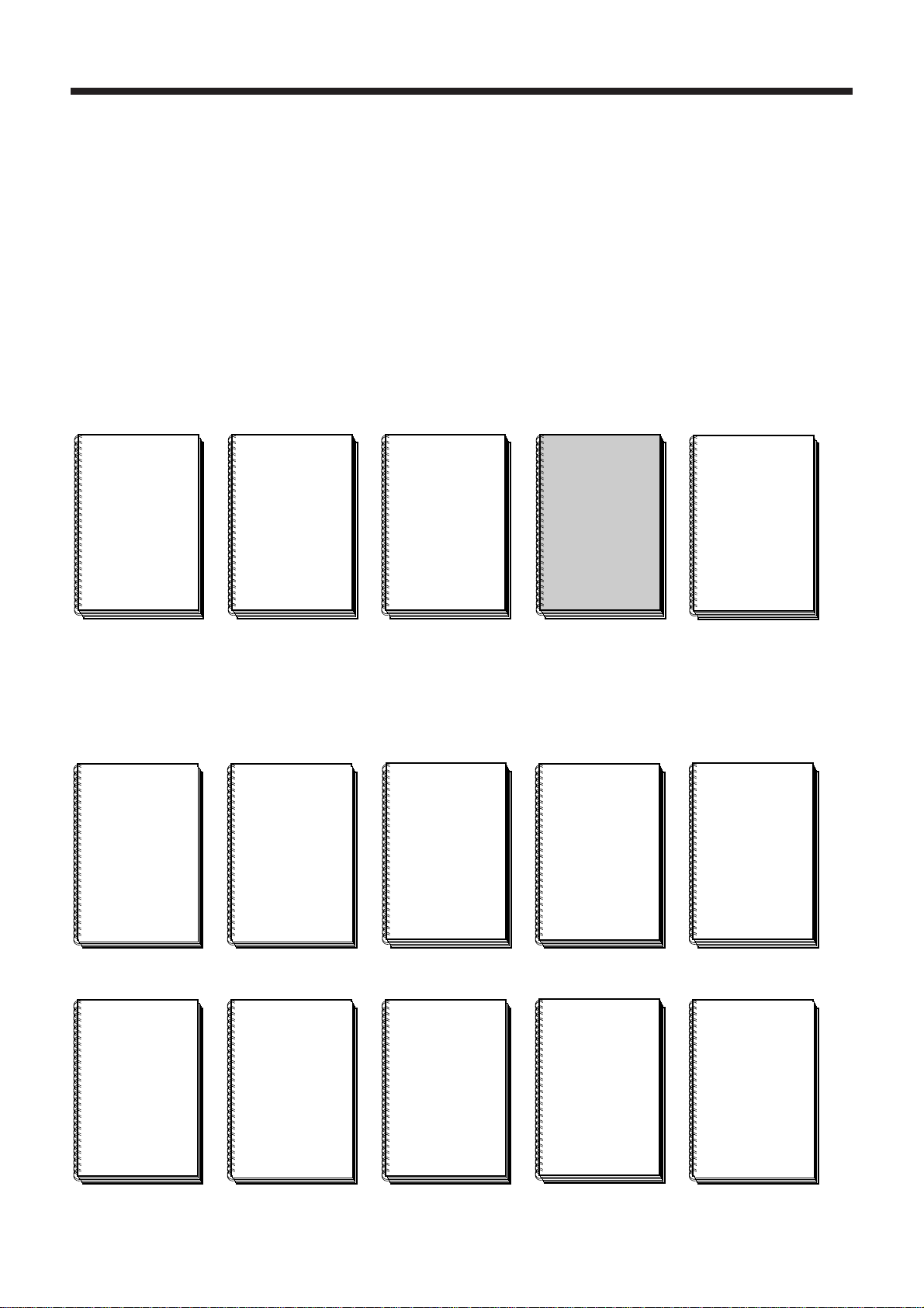
Structure of the NUM 1020/1040/1060 Documentation
User Documents
These documents are designed for the operator of the numerical control.
Foreword
Foreword
NUM
M/W
OPERATOR’S
MANUAL
938821
OEM Documents
NUM
1060
INSTALLATION
AND
COMMISSIONING
MANUAL
938816
NUM
T
OPERATOR’S
MANUAL
938822
These documents are designed for the OEM integrating the numerical control on a
machine.
NUM
1020/1040
INSTALLATION
AND
COMMISSIONING
MANUAL
938938
NUM
M
PROGRAMMING
MANUAL
V
OLUME
OLUME
938819
NUM
MANUAL
938818
1
2
V
PARAMETER
NUM
T
PROGRAMMING
MANUAL
V
OLUME
OLUME
938820
NUM
MANUAL
LADDER
938846
1
2
V
AUTOMATIC
CONTROL
FUNCTION
PROGRAMMING
LANGUAGE
NUM
G
CYLINDRICAL
GRINDING
PROGRAMMING
MANUAL
938930
NUM
DYNAMIC
OPERATORS
938871
NUM
PROCAM
DESCRIPTION
MANUAL
938904
NUM
G
CYLINDRICAL
GRINDING
COMMISSIONING
MANUAL
938929
NUM
H/HG
GEAR
CUTTING AND
GRINDING
MANUAL
938932
NUM
TWO-SPINDLE
SYNCHRONISATION
MANUAL
938854
NUM
GS
SURFACE
GRINDING
MANUAL
938945
en-938820/5 11
Page 12
OEM Documents (cont’d)
These documents are designed for the OEM integrating the numerical control on a
machine.
NUM
SETTOOL
PARAMETER
INTEGRATION
TOOL
938924
NUM
PLCTOOL LADDER
LANGUAGE
PROGRAMMING
TOOL
938859
Special Programming Documents
These documents concern special numerical control programming applications.
NUM
SUPPLEMENTARY
PROGRAMMING
MANUAL
NUM
M
PROCAM MILL
INTERACTIVE
PROGRAMMING
MANUAL
NUM
MMITOOL
MAN/MACHINE
INTERFACE
CUSTOMISATION
TOOL
938946
NUM
T
PROCAM TURN
INTERACTIVE
PROGRAMMING
NUM
DUPLICATED
AND
SYNCHRONISED
AXES
NUM
PROFIL
FUNCTION
USER’S
MANUAL
938872
NUM
G
PROCAM GRIND
INTERACTIVE
PROGRAMMING
938931
12 en-938820/5
938873
NUM
POLYGON
CUTTING
MANUAL
938952
938874
NUM
GS
PROCAM GRIND
INTERACTIVE
PROGRAMMING
938953
938875
NUM
T
PROCAM
TURN
TECHNOLOGICAL
DATA
938959
938937
NUM
M
PROCAM
MILL
TECHNOLOGICAL
DATA
938958
Page 13
Programming Manual
CHAPTER 1
REVIEW
Foreword
General description of the NC and its use with the machine tool.
Review of the rules and standards related to the NC/machine-tool combination.
CHAPTER 2
STRUCTURE
OF A
PROGRAMME
CHAPTER 3
AXIS
PROGRAMMING
Rules for writing a part programme by assembling characters into words, words into
blocks and blocks into a complete programme.
Description of the features related to axis programming.
Detailed description of functions related to ISO programming.
CHAPTER 4
ISO
PROGRAMMING
en-938820/5 13
Page 14
CHAPTER 5
PROFILE
GEOMETRY
PROGRAMMING
CHAPTER 6
PARAMETRIC
PROGRAMMING
Detailed description of profile geometry programming (PGP).
Description of access to the Profil function and the contour call created by Profil.
PGP and Profil are used to define contours as a sequence of geometric elements,
with computation of intermediate points. PGP and Profil are extensions of ISO
programming.
Gives the possibility of assigning variables to NC functions. The values of the
variables can be obtained by computation or by reading machine data.
Possibility of saving or restoring a chain of L variables in a single instruction.
CHAPTER 7
PROGRAMME
STACK-
L VARIABLES
AND SYMBOLIC
VARIABLES
CHAPTER 8
PROGRAMMING
OF ERROR
NUMBERS AND
MESSAGES
14 en-938820/5
Possibility of naming the variables used in a part programme to make the programme
easier to read.
Gives the possibility of programming and displaying error numbers and messages.
Page 15

APPENDIX A
FUNCTION
SUMMARY
TABLES
Foreword
Tables given as lists of:
- G preparatory functions,
- M miscellaneous functions,
- other functions.
APPENDIX B
EXTERNAL
PARAMETER E
SUMMARY
TABLES
APPENDIX C
WORD
FORMAT
SUMMARY
TABLE
Tables given as lists of:
- exchange parameters with the PLC,
- parameters stored in the NC memory.
Table given as a list of words with their associated formats.
List of NC error numbers and definitions.
APPENDIX D
LIST OF
ERRORS
en-938820/5 15
Page 16
Use of this Programming Manual
(
)
Function Syntax Entry Conventions
The lines (blocks) of a part programme include several functions and arguments.
Special syntax rules apply to each of the functions described herein. These syntax
rules specify how the programme blocks must be written.
Certain syntax formats are given as a line. The following conventions simplify writing
the line:
- the function to which the syntax format is related is highlighted by boldface type,
- terms between square brackets «[..]» are optional functions or arguments in the
block (or functions activated earlier, with values unchanged, etc.) (except Sec. 6.6
and Chapter 7),
- «/» indicates a choice between several terms (equivalent to «or») (except Sec. 6.6
and Chapter 7),
- «..» after a letter replaces a numerical value,
- «...» replaces a character string (for instance a message).
Examples
Syntax of function G12
NC Operating Modes
N.. [G01/G02/G03] G12 X.. Z.. [F..] [$0…]
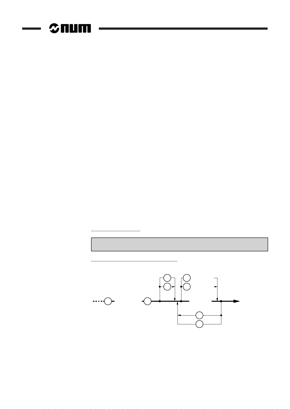
Syntax in the form of a Conway diagram
+
–
1 to 3 digits
L
(
Certain NC operating modes are mentioned herein when they are directly related to
the use of ISO functions. For additional information on these modes, refer to the
Operator Manual.
=
)
E
L
Parameter
(
1 to 3 digits
Value
8 digits
(
5 digits
Variable
)
max
+
–
)
16 en-938820/5
Page 17

Optional Functionalities
The use of certain functionalities described herein requires validating the associated
options. The «OPTIONS» system page is used to check for the presence of these
functionalities (for access to the «OPTIONS» page and the list of functionalities, see
Chapter 2 of the Operator Manual).
List of G, M and Other Functions
The lists at the beginning of the manual indicate the pages where the G, M and other
functions are found (yellow pages).
Foreword
Index
Agencies
Questionnaire
The index at the end of the manual facilitates access to information by keywords.
The list of NUM agencies is given at the end of the manual.
To help us improve the quality of our documentation, we kindly request you to return
the questionnaire at the end of the manual.
en-938820/5 17
Page 18

18 en-938820/5
Page 19

G Functions
Lists of G, M and Other Functions
Lists of G, M and Other Functions
Code Description Page
G00 High-speed linear interpolation 4 - 29
G01 Linear interpolation at programmed feed rate 4 - 32
G02 Clockwise circular interpolation at programmed feed rate 4 - 36
G03 Counterclockwise circular interpolation at programmed
feed rate 4 - 36
G04 Programmable dwell 4 - 238
G05 Movement on an inclined axis 4 - 269
G06 Spline curve execution command 4 - 216
G07 Initial tool positioning before machining on an inclined axis 4 - 268
G09 Accurate stop at end of block before going to next block 4 - 59
G10 Interruptible block 4 - 180
G12 Overspeed by handwheel 4 - 242
G16 Definition of tool axis orientation with addresses P, R 4 - 72
G20 Programming in polar coordinates (X, Z, C) 4 - 226
G21 Programming in cartesian coordinates (X, Y, Z) 4 - 229
G22 Programming in cylindrical coordinates (X, Y, Z) 4 - 234
G23 Circular interpolation defined by three points 4 - 44
G33 Constant lead thread cutting 4 - 92
G38 Sequenced thread cutting 4 - 99
G40 Tool radius offset (cutter compensation) cancel 4 - 80
G41 Left tool radius offset (cutter compensation) 4 - 79
G42 Right tool radius offset (cutter compensation) 4 - 79
en-938820/5 19
Page 20

Code Description Page
G48 Spline curve definition 4 - 216
G49 Spline curve deletion 4 - 216
G51 Mirroring 4 - 261
G52 Programming of movements in absoluted dimensions
with reference to the measurement origin 4 - 203
G53 DAT1 and DAT2 offset cancel 4 - 206
G54 DAT1 and DAT2 offset enable 4 - 206
G59 Programme origin offset 4 - 209
G63 Roughing cycle with groove 4 - 151
G64 Turn/Face roughing cycle 4 - 128
G65 Groove roughing cycle 4 - 140
G66 Plunging cycle 4 - 146
G70 Inch data input 4 - 244
G71 Metric data input 4 - 244
G73 Scaling factor cancel 4 - 259
G74 Scaling factor enable 4 - 259
G75 Emergency retraction subroutine declaration 4 - 189
G76 Transfer of the current values of «L» and «E» parameters
into the part programme 6 - 55
G76+/- ISO programme or block creation/deletion 4 - 198
G77 Unconditional branch to a subroutine or block sequence
with return 4 - 165
G77 -i Call of a subroutine return block 4-196
G78 Axis group synchronisation 4 - 279
G79 Conditional or unconditional jump to a sequence without
return 4 - 174
G79 +/- Temporary suspension of next block preparation in a
sequence with movements 4 - 187
20 en-938820/5
Page 21

Lists of G, M and Other Functions
Code Description Page
G80 Canned cycle cancel 4 - 91
G81 Centre drilling cycle 4 - 104
G82 Counterboring cycle 4 - 106
G83 Peck drilling cycle 4 - 108
G84 Tapping cycle 4 - 113
G84 Rigid tapping cycle 4 - 111
G85 Boring cycle 4 - 117
G87 Drilling cycle with chip breaking 4 - 119
G89 Boring cycle with dwell at hole bottom 4 - 122
G90 Programming in absolute dimensions with respect to the
programme origin 4 - 5
G91 Programming in incremental dimensions with respect to the
start of the block 4 - 5
G92 Programme origin preset 4 - 207
G92 R.. Programming of the tangential feed rate 4 - 66
G92 S.. Spindle speed limiting 4 - 27
G94 Feed rate expressed in millimetres, inches or degrees
per minute 4 - 61
G95 Feed rate expressed in millimetres or inches per revolution 4 - 64
G96 Constant surface speed expressed in metres per minute 4 - 15
G97 Spindle speed expressed in revolutions per minute 4 - 13
G98 Definition of the start X for interpolation on the C axis 4 - 228
G997 Enabling and execution of all the functions stored in
state G999 4 - 264
G998 Enabling of execution of the blocks and part of the functions
processed in state G999 4 - 264
G999 Suspension of execution and forcing of block concatenation 4 - 264
en-938820/5 21
Page 22

M Fonctions
Code Description Page
M00 Programme stop 4 - 248
M01 Optional stop 4 - 250
M02 End of programme 2 - 9
M03 Clockwise spindle rotation 4 - 11
M04 Counterclockwise spindle rotation 4 - 11
M05 Spindle stop 4 - 11
M06 Tool change 4 - 70
M07 Coolant 2 on 4 - 247
M08 Coolant 1 on 4 - 247
M09 Coolant off 4 - 247
M10 Clamp 4 - 246
M11 Unclamp 4 - 246
M12 Programmed feed stop 4 - 240
M19 Spindle index 4 - 21
M40 to M45 Spindle speed ranges 4 - 20
M48 Enable overrides 4 - 255
M49 Disable overrides 4 - 255
M61 Release of current spindle in the axis group 4 - 278
M62 to M65 Control of spindles 1 to 4 4 - 23
M66 to M69 Measurement of spindles 1 to 4 4 - 25
M997 Forced block sequencing 4 - 254
M998 Reactivation of edit (EDIT) and manual data input (MDI)
modes and subroutine calls by the automatic control function 4 - 252
M999 Programmed cancellation of the edit (EDIT) and manual data
input (MDI) modes and subroutine calls by the automatic
control function 4 - 252
22 en-938820/5
Page 23

Other Functions
Lists of G, M and Other Functions
Code Description Page
$0 Message transmission to the display 4 - 288
$1 to $6 Message transmission to the PLC function or a remote
server or a peripheral 4 - 290
/ Block skip 4 - 256
D.. Call to tool correction 4 - 74
ED.. Programmed angular offset 4 - 215
EG.. Programmed acceleration modulation 4 - 258
T Tool number 4 - 70
M Conversion of the internal unit of rotary axes 6-6 and 6-19
U Conversion of the internal unit of linear axes 6-6 and 6-19
en-938820/5 23
Page 24

24 en-938820/5
Page 25

Review
1 Review
1.1 System Overview 1 - 3
1.1.1 Overview of Modes 1 - 3
1.1.2 Defining a Programme 1 - 3
1.1.3 Preparating a Programme 1 - 4
1.2 Machine Overview 1 - 5
1.2.1 Review of Axis Definition and Direction 1 - 5
1.2.2 Machine Overview 1 - 6
1.2.3 Definition of Travels and Origins 1 - 7
1.2.4 Offset Definitions 1 - 9
1.2.5 Definition of the Tool Dimensions 1 - 12
1.2.5.1 Definition of the Tool Dimensions 1 - 12
1.2.5.2 Definition of Tool Tip Radius and
Orientation 1 - 13
1.2.6 Definition of Dynamic Tool Corrections 1 - 14
1
en-938820/5 1 - 1
Page 26

1 - 2 en-938820/5
Page 27
The aim of this chapter is to introduce concepts that will be detailed in the rest of the
MODE
manual, rather than to reflect the way an operator works on the machine.
For instance, in Section 1.2.4 (Offset Definition), the aim is to define the offsets and
corresponding origins or zero points rather than give a method for measuring the
offsets.
1.1 System Overview
1.1.1 Overview of Modes
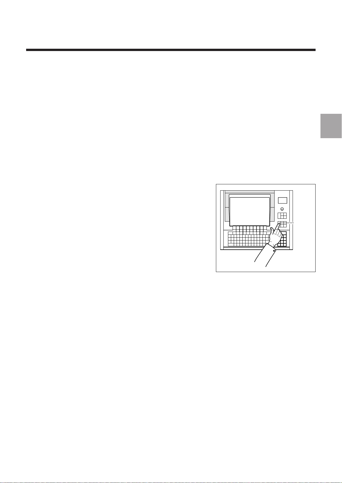
The operator uses the numerical control
(NC) in various operating modes accessible from the operator panel.
Review
1
Each mode corresponds to a particular
use of the numerical control (continuous-machining, programme loading, tool
setting, etc.).
1.1.2 Defining a Programme
A programme is a sequence of instructions written in a programming language
specific to the numerical control (the most widely used is ISO code: International
Standards Organization).
The numerical control interprets the programme to control actions on a machine-tool.
The most widespread storage media for programmes are punched tape and
diskettes.
en-938820/5 1 - 3
Page 28
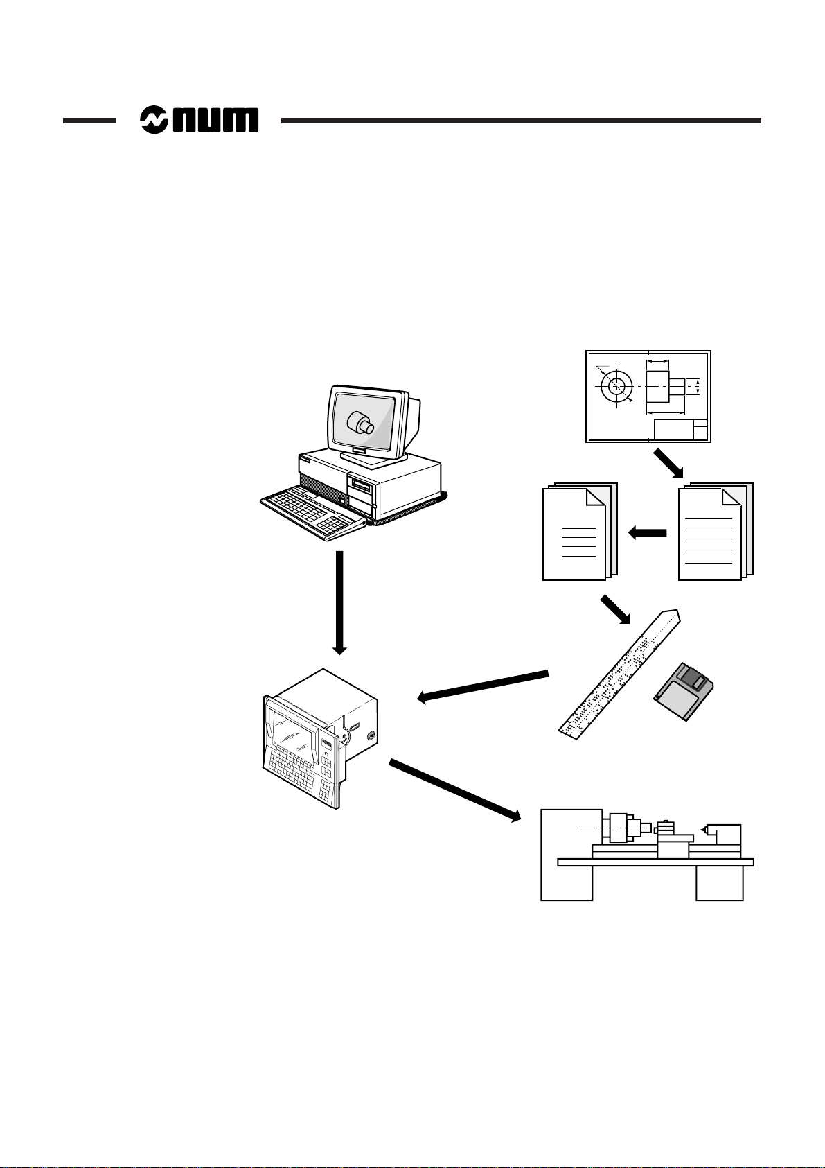
1.1.3 Preparating a Programme
A part programme can be created by traditional programming or using a CAD/CAM
system.
CAD/CAM
Part
Programme
% 1
N10
N20
N30
Machining
instructions
1 - 4 en-938820/5
Page 29
1.2 Machine Overview
Z
C
B
A
X
0
Y
X
Y
Z
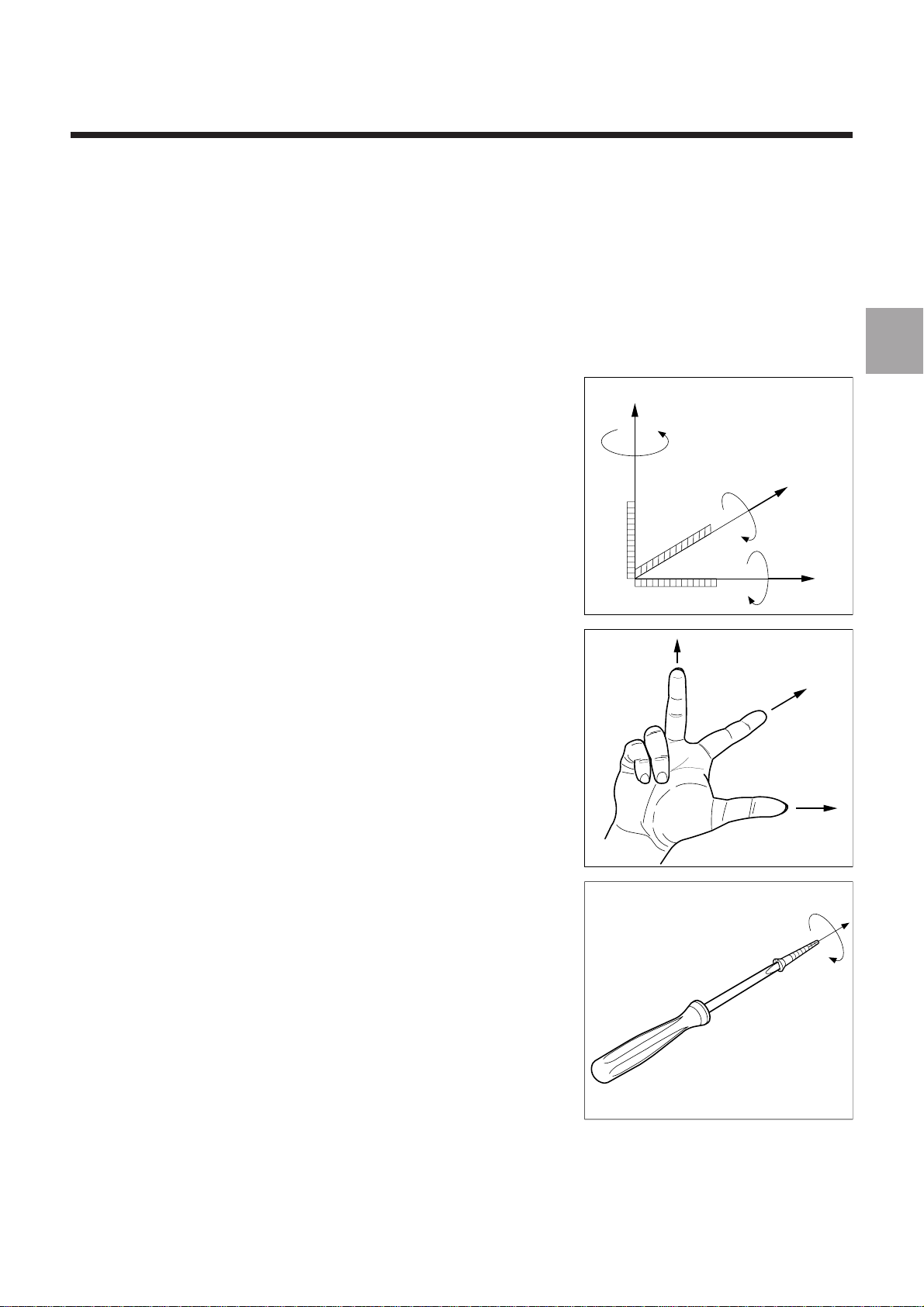
1.2.1 Review of Axis Definition and Direction
A coordinate system is used to identify
the positions and movements of an object
with respect to an origin or zero point.
A rectangular cartesian coordinate
system is a direct three-axis system of
three linear axes, X, Y and Z, with which
are associated three rotary axes, A, B
and C.
Review
1
The direction of axes X, Y and Z is easily
remembered by the right-hand rule.
The positive direction of rotation of a
rotary axis corresponds to the direction
of screwing of a right-hand screw on the
associated axis.
en-938820/5 1 - 5
Page 30
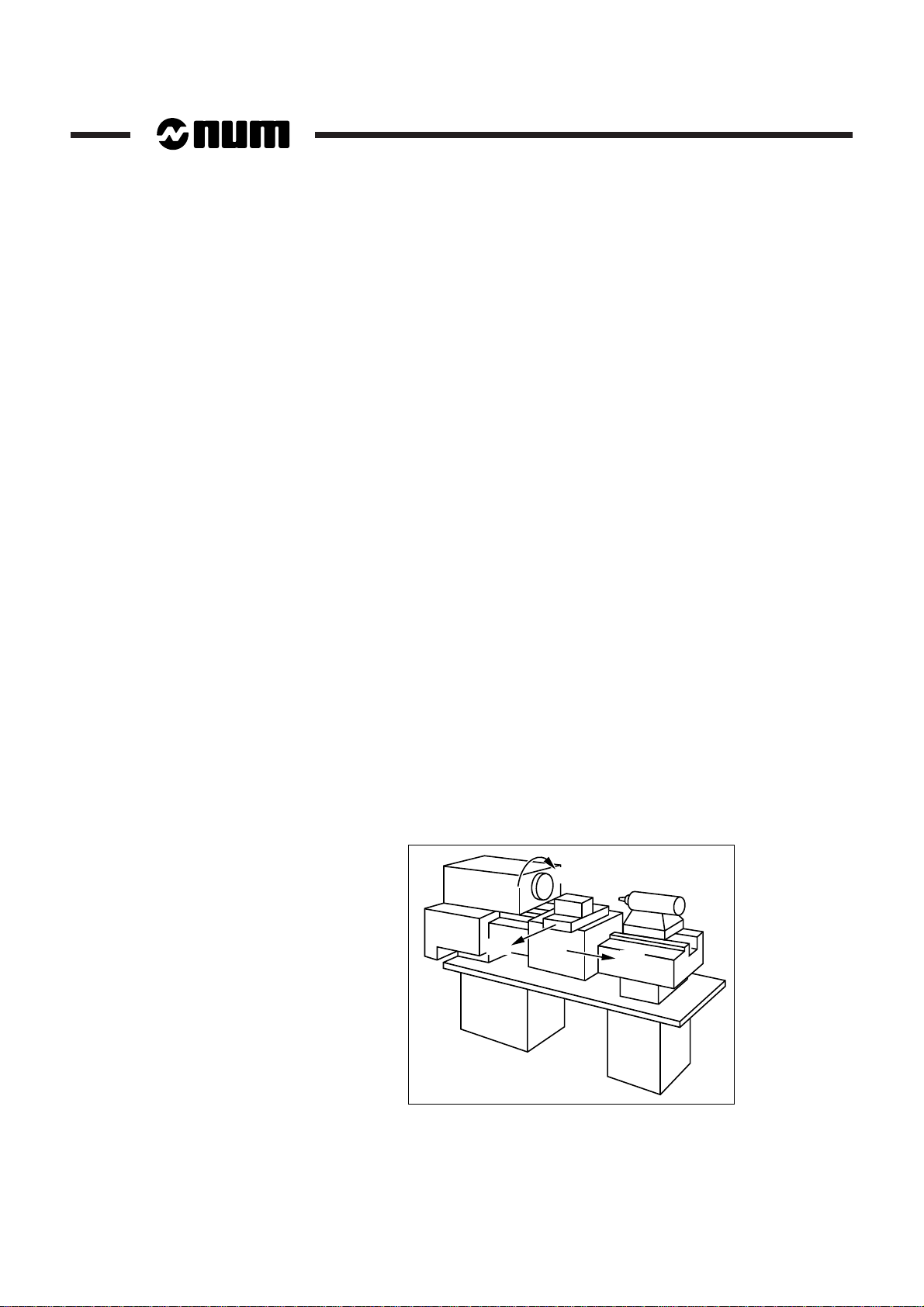
1.2.2 Machine Overview
The manufacturer defines the coordinate system associated with the machine in
accordance with standard ISO 841 (or NF Z68-020).
The X, Y and Z axes, parallel to the machine slideways, form a right-handed
rectangular cartesian coordinate system.
The coordinate system measures tool movements with respect to the part to be
machined, assumed fixed.
REMARK When it is the part that moves, it may be more convenient to identify its
movements. In this case, axes X’, Y’ and Z’, pointing in opposite
directions from axes X, Y and Z, are used.
The direction of the axis of a machine depends on the type of machine and the layout
of its components.
For a lathe:
- the Z axis is the same as the spindle axis,
- the X axis is perpendicular to the Z axis and corresponds to radial movement of
- the Y axis (generally a dummy axis) forms a right-handed coordinate system with
Positive movement along the Z or X axis increases the distance between the part and
the tool.
Rotary axes A, B and C define rotations around axes parallel to X, Y and Z.
the tool-holder turret,
the X and Z axes.
Secondary linear axes U, V and W may or may not be parallel to primary axes X, Y
and Z.
For more details, refer to the above-mentioned standard.
+ C'
+ X
+ Z
1 - 6 en-938820/5
Page 31

1.2.3 Definition of Travels and Origins
MOS direction
Om
Min. limite
switch
Max limit
switch
Contact closed Contact open
One encoder revolution
Encoder marker pulse
Review
OM :
Om :
The NC processor computes all movements with respect to the measurement origin
or zero point of the machine.
When the system is turned on, it does not know the measurement origin. The
mechanical travel on each machine axis is limited by maximum and minimum limit
switches.
The system establishes the measurement origin (OM) via a homing procedure
(MOS).
The home switch is set in a specific physical location: the machine zero point (Om)
may or may not be the same as the measurement origin (OM).
The homing procedure is completed for each of the axes when:
- the origin limit switch is actuated in the direction of movement specified by the
m/c manufacturer (MOS direction),
- the encoder which measures axis movement outputs its marker pulse.
1
en-938820/5 1 - 7
Page 32

When homing (MOS) is completed, the system applies the offset defined by the
X
Z
Mechanical travel on Z (limit switch)
Useful travel on Z
Accessible
area
Origin switch
encoder zero
Om
ORPOM Z
OM
ORPOM X
Useful travel on X
Mechanical travel
on X (limit switch)
manufacturer to each of the axes to establish the measurement origin (OM).
Measurement origin offset (OM/Om) = ORPOM
The useful travel on each of the axes is limited by software limits whose values are
defined by the machine parameters.
1 - 8 en-938820/5
Page 33

1.2.4 Offset Definitions
Review
OP :
Op :
To write a part programme, the programmer chooses a programme origin.
The programme origin is generally a starting point for dimensional measurements on
the part drawing.
The operator sets the programme origin (OP) as shown below:
He sets (for each axis) a known, accessible point on the part, called the part origin,
(Op). This may be the same point as the programme origin.
Part origin offset (Op/OM) = DAT1
It is possible to set the DAT1, DAT2 values from the part programme.
Programme origin offset (OP/Op) = DAT2
Offsets on the Z axis
Z
Turret
Setting block
Measurement
origin
(OM)
1
Z
OP
Z DAT2
Op
Turret
reference
Z DAT1
en-938820/5 1 - 9
Page 34

Offsets on the X axis (solution with DAT2)
X
Measurement
origin
(OM)
Setting
block
Turret
reference
X DAT1
Op
X DAT2
OP
X
Turret
X
Z
Measurement
origin
(OM)
Turret
reference
X DAT1
OP
X
Turret
Op
X
Offsets on the X axis (solution without DAT2)
X DAT1: Fixed value measured between OM and the spindle axis.
1 - 10 en-938820/5
Page 35

Review
OM
OP
Op
Z
X
Z
X
Z DAT1
Z DAT2
Z
PA
Z
MA
X
MA
X DAT1
X DAT2
X
PA
A
PART
The coordinates of a point (A) defined with respect to the programme origin (OP) are
converted by the NC to coordinates with respect to the measurement origin (OM):
1
Programme dimensions Measurement dimensions
(with respect to OP) (with respect to OM)
X
Z
PA
PA
Programmed shifts can be added to the programme dimensions.
XMA = XPA + X DAT1 + X DAT2
ZMA = ZPA + Z DAT1 + Z DAT2
en-938820/5 1 - 11
Page 36

1.2.5 Definition of the Tool Dimensions
1.2.5.1 Definition of the Tool Dimensions
Tool dimension = distance from tool cutting edge to turret reference point
X
Turret reference
point
OP
Part/tool
contact
diameter
X
Z
Tool axis orientation
OP
Z
Dimension Z
Part/tool contact
face
Turret reference
point
Dimension X
1 - 12 en-938820/5
Tool X dimension = X
Tool Z dimension = Z
Page 37

1.2.5.2 Definition of Tool Tip Radius and Orientation
Review
The description of a tool is shown below:
Tool tip orientation = codes C0-C8
The tool tip orientation code allows the
system to locate the centre (C) of the tool
tip from the theoretical cutting point (P).
Tool tip radius = R
Example :
X
C3 C2 C1
C4
C5 C6 C7
C0 C8
P
1
X
C1
P
Z
Z
The real cutting point of the tool is
obtained by applying a vector of length R
perpendicular to the direction of
movement from C.
X
Movement
R
P
Turret
Z dimension
C
en-938820/5 1 - 13
reference
X dimension
Z
Page 38

1.2.6 Definition of Dynamic Tool Corrections
At any time (even during machining), the operator can enter dynamic tool corrections
when he observes a difference between the expected and the actual results on a part.
The corrections (positive or negative) compensate for slight dimensional variations
of the tool or part (wear, expansion).
Dynamic tool correction on X = DX (diameter)
Dynamic tool correction on Z = DZ
D
L
L + ∆L
D + ∆D
TOOL
DX = -∆D
DZ = -∆L
The system takes into account the corrected tool dimensions:
Corrected length on X = X dimension + DX/2
Corrected length on Z = Z dimension + DZ
X + DX/2
Z + DZ
1 - 14 en-938820/5
Page 39

Structure of a Programme
2 Structure of a Programme
2.1 Word Format 2 - 4
2.1.1 General Word Format 2 - 4
2.1.2 Special Features of the Dimension Word
Format 2 - 4
2.1.2.1 Internal System Unit for Linear Axes 2 - 5
2.1.2.2 Internal System Unit for Rotary Axes 2 - 5
2.2 Block Format 2 - 7
2.3 General Structure of a Programme 2 - 9
2.3.1 General 2 - 9
2.3.2 Branches and Subroutine Calls 2 - 11
2.3.3 Programme Numbering 2 - 12
2.3.4 Characteristics of the ISO and EIA Codes 2 - 13
2.4 Classification of Preparatory G Functions and Miscellaneous M Functions 2 - 18
2.4.1 Classification of Preparatory G Functions 2 - 18
2.4.1.1 Modal G Functions 2 - 18
2.4.1.2 Nonmodal G Functions 2 - 18
2.4.1.3 G Functions Incompatible with the State
of the Programme 2 - 18
2.4.1.4 G Functions Associated with Arguments 2 - 19
2.4.2 Classification of Miscellaneous
M Functions 2 - 21
2.4.2.1 Modal M Functions 2 - 21
2.4.2.2 Nonmodal M Functions 2 - 21
2.4.2.3 «Pre» M Functions 2 - 21
2.4.2.4 «Post» M Functions 2 - 21
2.4.2.5 Encoded M Functions 2 - 22
2.4.2.6 Decoded M Functions 2 - 22
2
en-938820/5 2 - 1
Page 40

2 - 2 en-938820/5
Page 41

Structure of a Programme
A CNC part programme is a list of instructions and data to be transmitted to the control
system.
The creation of a programme consisting of blocks and words must obey structure,
syntax and format rules.
The programmes are variable in length with addresses as per the ISO and EIA codes
and standards.
Programming is possible in both codes:
- ISO (International Standards Organization) 6983-1 (NF Z 68-035), 6983-2
(NF Z 68 036) and 6983-3 (NF Z 68-037).
- EIA (Electronic Industries Association) Standards RS 244 A and 273 A.
PROGRAMME
%10
N10
N..
N..
N50 G01 X20.45 F0.15 M08
N..
N..
BLOCK
2
N250
XOFF
M02
WORD
en-938820/5 2 - 3
Page 42

2.1 Word Format
A word contains an instruction or data to be transmitted to the control system.
Word types:
- words defining dimensions
- words defining functions.
The word format defines the specific characteristics of each code word used in
programming (see table, Appendix C).
2.1.1 General Word Format
Address Algebraic sign Numerical data
WORD
Digits related to the address
Sign, possibly plus (+) or minus (-)
One or two letters or a digit
REMARK For words defining a dimension, the decimal point is generally explicit.
It separates the digits before and after the decimal point (it does not
appear in the definition of the word format).
The number of characters and spaces in a block must not exceed 118.
2.1.2 Special Features of the Dimension Word Format
The format of dimension words is determined by the choice of the internal system
units specified by the OEM when integrating the CNC.
Internal system units are specified for:
- Linear axes
- Rotary axes.
The internal units directly affect the machine travels and the dimension acquisition
and display formats for linear and rotary axes (modulo or not).
2 - 4 en-938820/5
Page 43

2.1.2.1 Internal System Unit for Linear Axes
The number of decimal digits available for programming the linear axes (where the
basic unit is the mm) is declared in machine parameter P4, word N2 (see Parameter
Manual).
Structure of a Programme
Correspondence between the word format and internal unit for linear axes
Internal unit Definition Word format
0.1 mm 1 decimal digit Format 071
0.01 mm 2 decimal digits Format 062
µm 3 decimal digits Format 053
0.1 µm 4 decimal digits Format 044
0.01 µm 5 decimal digits Format 035
2.1.2.2 Internal System Unit for Rotary Axes
The number of decimal digits available for programming the rotary axes (for which the
basic unit is the degree) is declared in machine parameter P4, word N4 (see
Parameter Manual).
Correspondence between the word format and the internal system unit for
rotary axes
2
Internal unit Definition Word format
0.1 degree 1 decimal digit Format 031
0.01 degree 2 decimal digits Format 032
0.001 degree 3 decimal digits Format 033
0.0001 degree 4 decimal digits Format 034
en-938820/5 2 - 5
Page 44

Examples of word formats:
X+053
Maximum number of digits
after the decimal point
Maximum number of digits
before the decimal point
Leading zeros are optional
The «+» sign is optional
Word address
Word defining a dimension, address X (internal unit in µm)
The dimension 0.450 mm in X+053 format (variable word format), can be written:
X+0.450 or X.45
Word defining a function, address G
G02
Word address
G function words in G02 format (variable word format).
Word G01 can be written: G1
Word G04 can be written: G4
Maximum number of digits
with the address
Leading zeros are optional
2 - 6 en-938820/5
Page 45

2.2 Block Format
Structure of a Programme
A block (or sequence) defines an instruction line of code words to be actioned by the
control system.
The block format defines the syntax of the function and dimension words in each
programming block.
BLOCK
N.. G.. X.. F.. M..
2
Miscellaneous function word
Technological function word
Dimension word
Preparatory function word
Block number
Examples of blocks
A block defining a tool change and calling up the tool correction
N20 T01 D01 M06
Tool change
Correction number
Tool number
Block number
en-938820/5 2 - 7
Page 46

A block defining spindle rotation
N30 S650 M41 M03
Spindle range
Speed of rotation
Block number
A block defining a move
Direction of rotation
N50 G01 X20.456 F150
End point
Linear interpolation
Block number
M08
Coolant
Feed rate
2 - 8 en-938820/5
Page 47

2.3 General Structure of a Programme
2.3.1 General
An NC programme must include start and end characters.
A programme is executed in the order in which the blocks are written between the
programme start and end characters.
A programme is executed in the order in which the blocks are written, and not in the
order of the block numbers. However, it is recommended to number the blocks in
ascending order (in increments of ten, for instance).
REMARK A programme can be written in ISO code or EIA code. The ISO or EIA
code is recognised by the system by reading the programme start
character.
Structure of a Programme
2
Structure of an ISO Programme
Programme start: % character
Programme end: code M02
Programme end of load: XOFF character
en-938820/5 2 - 9
Page 48

Programme start character
Programme number
%
1
N10
N20
N30
N..
N..
N..
N..
N250
XOFF
Programme end character
Structure of an EIA programme
An EIA programme has the same structure as an ISO programme except for the
programme start and end characters, which are different.
Programme start: EOR (End of Record) character
Programme end: BS (Back Space) character
M02
Programme
Miscellaneous programme
end function
REMARK For an EIA programme, a programme end character other than BS can
2 - 10 en-938820/5
be declared by machine parameter P80 (see Parameter Manual).
Page 49

2.3.2 Branches and Subroutine Calls
Particular instructions (branches and subroutine calls) can modify the order in which
a programme is executed.
A programme can be structured as follows:
Main programme Subroutine
Structure of a Programme
2
%10 (……)
$0…
N10 G .. G.. X.. Z..
N.. T.. D.. M.. (....)
N... ...
N50...
N... ...
N... ...
N100 Call to a sequence of blocks (N50...)
N... ...
N150 Call to a subroutine
N... ...
N200 Jump to a numbered block
N... ...
N250 M02
X OFF
%20
$0…
N10...
N... ...
N220...
X OFF
en-938820/5 2 - 11
Page 50

2.3.3 Programme Numbering
Programme number: The permissible format is %051.
The % character is followed by a programme number and possibly by a comment in
brackets.
Example:
%324 (PART No. 72 - PROG 3)
A programme number can be indexed (indices .1 to .8 with multiple axis group
programming, see Sec. 4.15).
Example:
%425.2 (PROG FOR GROUP 2)
!
CAUTION
Programmes with numbers above %9000 are reserved for NUM and the OEM integrating
the NC on the machine (check with NUM or the OEM for possible use of these numbers).
Programme Number and ISO Functions
When ISO functions are programmed after the programme (or subroutine) number
on the same line, they are ignored.
Example:
%99 G1 X80
Programme Load from a Peripheral
When loading a programme from a peripheral, if the programme number does not
comply with format %051, the excess digits are ignored.
Example:
%1234567.89 (comment)
%12345 .8 (comment)
Inhibiting display of subroutines being executed
Display on the programme page (PROG) of a subroutine and its internal subroutines
during execution can be inhibited.
Placing the character «:» after the subroutine number (e.g. %110:) inhibits display.
Only the subroutine call block is then displayed (for additional information, see Sec.
4.11.1).
Movement G1 X80 is ignored
Programme number received over the line
Number actually stored
2 - 12 en-938820/5
Page 51

2.3.4 Characteristics of the ISO and EIA Codes
10 digits
Letters of the alphabet
Programme start
Start of comment
End of comment
Plus sign
Minus sign
Decimal point
Greater than
Less than
Multiplied by
Equal to
Divided by
At sign
End of block
Skip block
Programme subdivision
Programme end
0-9
A-Z
%
(
)
+
-
.
>
<
*
=
/
@
LF
/
:
X OFF
0-9
A-Z
EOR
,
%
+
.
CR
/
letter O
BS
DESCRIPTION ISO EIA
List of characters recognised by the system in ISO and EIA codes:
Structure of a Programme
2
List of characters recognised by the system with no action on the machine:
DESCRIPTION ISO EIA
Tab
Carriage return
Space
Error
HT
CR
SP
DEL
RUB OUT
TAB
SP
DEL
RUB OUT
en-938820/5 2 - 13
Page 52

Structure of an ISO programme tape:
LEADER
8 7 6 5 4 3 2 1
8 6 3 1
8 4 3 1
4 2
6 4
8 6 4 1
8 4 3 1
4 2
7 4 3 2
8 6 5 1
6 5
7 4 3 1
8 6 5 2
8 4 3 1
4 2
8 5 2 1
Channel numbers as per standards
Sprocket holes
%
CR
LF
I
I
I
(
)
CR
LF
N
1
0
I
I
I
I
I
I
I
I
I
I
I
M
2
CR
LF
CTRL-X-OFF
Comments
Part programme
End of programme
- Start of
programme
- End of
rewind
- End of tape
- Start of
rewind
2 - 14 en-938820/5
TRAILER
Page 53

List of characters used in ISO code:
ISO CODE
Channel No.
Function
Programme start, rewind stop
Plus sign
Minus sign
Digits
Angular direction about X axis
Angular direction about Y axis
Angular direction about Z axis
Tool correction
Peripheral parameter
Feed rate. Dwell
Preparatory function
Subroutine No.
Interpolation address
Interpolation address
Interpolation address
Programmer parameter No.
Miscellaneous function
Sequence number
Miscellaneous parameters
Spindle speed function
Tool No.
Secondary dimension parallel to X axis
Secondary dimension parallel to Y axis
Secondary dimension parallel to Z axis
Primary X dimension
Primary Y dimension
Primary Z dimension
Programme subdivision
Optional block skip
Carriage return
End of block/line feed
Start of comment
End of comment
Space
End of tape
Horizontal tab
Delete
No punch
Charac-
ter
%
+
0
1
2
3
4
5
6
7
8
9
A
B
C
D
E
F
G
H
I
J
K
L
M
N
O
P
Q
R
S
T
U
V
W
X
Y
Z
:
/
CR
LF
(
)
SP
X OFF
HT
DEL
NUL
Structure of a Programme
8 7 6 5 4 3 2 1
Tape punch
code
2
en-938820/5 2 - 15
Page 54

List of characters used in EIA code (RS.244.B):
EIA CODE
Channel No.
Function
Programme start, rewind stop
Plus sign
Minus sign
Digits
Angular direction about X axis
Angular direction about Y axis
Angular direction about Z axis
Tool correction
Peripheral parameter
Feed rate. Dwell
Preparatory function
Subroutine No.
Interpolation address
Interpolation address
Interpolation address
Programmer parameter No.
Miscellaneous function
Sequence number
Miscellaneous parameters
Spindle speed function
Tool No.
Secondary dimension parallel to X axis
Secondary dimension parallel to Y axis
Secondary dimension parallel to Z axis
Primary X dimension
Primary Y dimension
Primary Z dimension
Programme subdivision
Optional block skip
Carriage return
End of block/line feed
Start of comment
End of comment
Space
End of tape
Horizontal tab
Delete
No punch
Charac-
8 7 6 5 4 3 2 1
Tape punch
ter
EOR
+
0
1
2
3
4
5
6
7
8
9
a
b
c
d
e
f
g
h
i
j
k
l
m
n
o
p
q
r
s
t
u
v
w
x
y
z
o
/
EOB
?
%
SP
BS
TAB
DEL
NUL
code
2 - 16 en-938820/5
Page 55

Special ISO code characters:
8 7 6 5 4 3 2 1
Channel numbers
Charac-
ter
Description
Holes
punched
Less than
Greater than
Multiplied by
Equal to
Divided by or block skip
At sign
AND
OR
Dollar sign
Comma
Period
Single quote
Semicolon
Pound sign
Question mark
Double quote
<
>
*
=
/
@
&
!
$
,
.
'
;
#
?
"
Special characters
Structure of a Programme
2
The «$» character is used in a programme to send messages (see Sec. 4.19).
Most of the other characters are mainly used for parametric programming (see
Chapter 6).
Special characters of the EIA code:
As comments were not provided for by the EIA code, the characters «,» et «%» are
used and have the same meaning as round brackets «( )» in ISO code.
As there is no equivalence in EIA code for ISO characters «>», «<«, «*», «=» and
«@», parametric programming, tool data entry and tape punching are prohibited in
this code.
The absence of a character on an EIA tape is reported as a parity error.
en-938820/5 2 - 17
Page 56

2.4 Classification of Preparatory G Functions and Miscellaneous M Functions
2.4.1 Classification of Preparatory G Functions
Types of G functions:
- Modal G functions,
- Nonmodal G functions.
Certain G functions must be programmed with the associated arguments.
Programming of certain G functions may be incompatible with the state of the current
programme.
2.4.1.1 Modal G Functions
Functions belonging to a family of G functions that cancel one another.
Certain families of G functions include a default function that is initialised when power
is applied (see A.1).
These functions remain enabled until cancelled by another function of the same
family.
Example:
N.. G00 X.. Z..
N.. G01 Z..
High-speed linear interpolation
G00 cancelled by linear interpolation at
machining feed rate
2.4.1.2 Nonmodal G Functions
Functions enabled only in the block where they are programmed (cancelled at the end
of the block).
Example:
N.. G09 X..
2.4.1.3 G Functions Incompatible with the State of the Programme
Functions whose programming is enabled or not according to the state of the current
programme.
Example:
N.. G21 G42 X.. Y.. Z..
Accurate stop at end of block cancelled
at end of block.
Syntax correct, change of X Y Z
coordinate system (G21), followed by
radius offset (G42)
N..
N.. G42 G21 X.. Y.. Z..
Syntax incorrect, change of coordinate
system prohibited with radius offset
2 - 18 en-938820/5
Page 57

2.4.1.4 G Functions Associated with Arguments
Functions followed by one or more arguments that are specific to the G function
announcing them.
The argument(s) must immediately follow the function.
The analysis of the arguments of a G function is ended by reading a word that does
not belong to the list of arguments of this function.
Example:
N.. G04 F2 T03 F0.2
N.. G04 T03 F2 F0.2
When a G functions has several arguments, they can be programmed in any order
except for G functions that introduce breaks in the sequencing (G10, G76, G77 and
G79, see Sec. 4.11).
Structure of a Programme
2
Syntax correct
Syntax incorrect, argument F2 does not
immediately follow G04
The arguments associated with a function can be:
- compulsory,
- optional.
The argument of certain G functions can be programmed alone in a block.
Compulsory Arguments
The arguments are compulsory if:
- the G function serves only to announce arguments.
Example:
N.. G16 P+
- the G function cancels a former modal state and characterises its argument
differently.
Example:
N.. G94 F100
G function and its argument P+
Feed in mm/min
N..
N.. G95 F0.5
Optional Arguments
The arguments are optional if the G function allows them to be defined by default.
The change from feed in mm/min to
mm/revolution requires redefining
argument F
Example:
N.. G96 [X..] S150
Case where the X position (with respect
to OP) was specified by an earlier block
en-938820/5 2 - 19
Page 58

Arguments Programmed Alone
The argument can be programmed alone in a block when the associated G function
is still active.
Example:
N.. G94 F150 X.. Z..
Feed in mm/min
N..
N.. X.. Z.. F100
Function G94 is not compulsory with its
argument because the system is still in
state G94.
2 - 20 en-938820/5
Page 59

2.4.2 Classification of Miscellaneous M Functions
Type of M functions:
- Modal M functions,
- Nonmodal M functions.
Structure of a Programme
M functions can be:
- «pre» or «post» functions,
- encoded or decoded functions.
2.4.2.1 Modal M Functions
Functions belonging to a family of M functions that cancel one another.
Certain families of M functions include a default function that is initialised when power
is applied (see A.2).
These functions remain enabled until they are cancelled by another function of the
same family.
Example:
N.. S500 M03
N.. M05
2.4.2.2 Nonmodal M Functions
Enabled only in the block where they are programmed.
Example:
N.. M00
2.4.2.3 «Pre» M Functions
Functions executed before axis movements programmed in the block.
2
Start of spindle rotation
Spindle stop, cancels M03
Programme stop
Example:
N.. X100 Z50 M08
2.4.2.4 «Post» M Functions
Functions executed after the axis movements programmed in the block.
Example:
N.. X50 Z100 M09
Coolant function M08 is executed before
the movements on X and Z
The coolant off function (M09) is
executed after movements on X and Z
en-938820/5 2 - 21
Page 60

2.4.2.5 Encoded M Functions
The encoded functions are defined by the machine manufacturer and are specific to
the machine (see manufacturer’s technical data).
Encoded Functions M100 to M199
These functions with PLC handshake are generally nonmodal «post» functions, but
these features can be redefined by the machine manufacturer.
Only one of these functions is allowed in a part programme block.
Encoded Functions M200 to M899
These so-called on-the-fly functions are modal «pre» functions. The programme
continues without waiting for the execution report.
Only one of these functions is allowed in a part programme block.
REMARK An encoded nonmodal function (M100 to M199) can be programmed
in the same block with an encoded modal function (M200 to M899).
2.4.2.6 Decoded M Functions
The decoded M functions are the basic system functions whose meaning is known.
REMARK All these functions are acknowledged by a PLC handshake (CRM). The
acknowledgement enables continuation of the part programme.
2 - 22 en-938820/5
Example:
N.. T01 M06
Several decoded M functions can be programmed in the same block.
Example:
Tool change function M06
N.. G97 S500 M03 M40 M08
Page 61

Axis Programming
3 Axis Programming
3.1 General 3 - 3
3.2 Programming the Independent Secondary Axes 3 - 4
3.3 Programming Carrier/Carried Parallel Axis Pairs 3 - 5
3.4 Programming of Rotary Axes Modulo 360 Degrees 3 - 6
3.5 Programming of Slaved Rotary Axes with Limited Travel 3 - 7
3.6 Programming of Axes A, B or C Declared as Nonrotary 3 - 7
3.7 Features of Front Turret, Rear Turret 3 - 8
3
en-938820/5 3 - 1
Page 62

3 - 2 en-938820/5
Page 63

3.1 General
Axis Programming
Programmable axes:
- Primary axes X, (Y), Z,
- Secondary axes U, (V), W,
- Rotary axes (A), (B), C.
Primary and secondary axes:
- they can be independent or form carrier/carried axis pairs (see machine parameter
P64),
- they can be programmed in millimetres (basic unit) or inches.
Rotary axes:
- They can be modulo 360 degrees or have limited travel or be declared as nonrotary (see machine parameter P1),
- They are programmed in degrees (basic unit).
3
Reminder
Definition of the Internal System Measurement Units
The internal measurement unit is defined by the OEM when integrating the CNC. It
directly affects the machine travels on the linear axes and rotary axes (modulo or not).
The number of decimal digits is declared in machine parameter P4 and determines
the word formats (see Sec. 2.1 and Appendix C).
For linear axes, the internal unit can be 0.1 mm, 0.01 mm, µm, 0.1 µm or 0.01 µm.
For rotary axes, the internal unit can be 0.1 degree, 0.01 degree, 0.001 degree or
0.0001 degree.
REMARK For ISO functions and programming arguments defining angular va-
lues (EA.., EC.., ED.., etc.), the unit is always 0.0001 degree.
For additional information, refer to:
- The machine manufacturer’s manual
- The Parameter Manual.
en-938820/5 3 - 3
Page 64

3.2 Programming the Independent Secondary Axes
Programming the independent secondary axes U, (V), W is unrelated to the
programming of the primary axes X, (Y), Z.
For a primary axis, the machine dimension is expressed:
Mx (machine dimension) = Px (programmed dimension) + xDAT1 + xDAT2 + tool
offset x
In the above example, x is the primary axis X (the equation is the same for the Y and
Z axes).
For an independent secondary axis, the same machine dimension is expressed:
Mu (machine dimension) = Pu (programmed dimension) + uDAT1 + uDAT2
In the above example, u is the independent secondary axis U (the equation is the
same for the (V) and W axes).
It should be noted that the tool length correction is not applied to the independent
secondary axes.
3 - 4 en-938820/5
Page 65

3.3 Programming Carrier/Carried Parallel Axis Pairs
Movement of the axis pair with respect to the part.
The U axis is a large slide and the X axis is a small slide.
Representation of large slide approach programmed by UP2
Calculation of UM2, knowing that XP2 = UP2.
Axis Programming
UM2 = UP2 = (DAT1 + DAT2 + X dimension) - XM1
X DAT1 + U DAT1 + DAT2
UM2
OM U
Representation of the small slide approach programmed by XP3
Calculation of XM3, knowing that XP3 = UP3.
XM3 = XP3 = (DAT1 + DAT2 + X dimension) - UM2
OM X
UM2
XM1
X DAT1 + U DAT1 + DAT2
X
UP2
Part origin
(Op)
Part
Programme
origin (OP)
3
OM U
OM X
XM3
XP3
Part origin
(Op)
X
Part
Programme
origin (OP)
en-938820/5 3 - 5
Page 66

3.4 Programming of Rotary Axes Modulo 360 Degrees
Rotary axis C programmed in absolute dimensions (G90)
The angular value assigned to the axis is the position of the end point with reference
to the programme origin, value between 0 and 360 degrees, maximum one revolution
(see Sec. 4.1 for function G90).
The sign (+ or -) determines the direction of rotation to reach this point.
Example:
a: Start point
b: End point
Positive rotation
+ (Positive)
(30°)
a
N.. ...
N.. G90 C+270
C0
X
N..
– (Negative)
Negative rotation
N..
+ 270°
b
– 270°
N.. G90 C-270
N..
Rotary axis C programmed in incremental dimensions (G91)
The value assigned to the axis indicates the amplitude of rotation of the axis with
reference to the previous position (see Sec. 4.1 for function G91).
Example:
a: Start point
b: End point
Positive rotation
N.. ...
N.. G91 C+240
+ (Positive)
a
C0
(30°)
X
N..
– (Negative)
Negative rotation
N..
+ 240°
b
– 120°
N.. G91 C-120
N..
3 - 6 en-938820/5
Page 67

REMARK With incremental programming G91 (see Sec. 4.1 for function G91), a
+ 45
+
–
0
- 495
movement of more than one revolution is allowed on modulo rotary
axes A, B or C. It should be noted that a maximum of 15 revolutions
are allowed. If this value is exceeded, the system returns error
message 1.
3.5 Programming of Slaved Rotary Axes with Limited Travel
Axis Programming
Servoed rotary axes A, B or C with limited travel are defined by machine parameters
like linear axes and therefore follow the same programming rules.
This definition of a rotary axis can be used for axes with more than 360 degrees of
travel to be rotated by more than one revolution with respect to a preferential position.
Example:
Rotation greater than one revolution Rotation greater than one revolution
in absolute dimensions (G90). in incremental dimensions (G91).
+
–
0
- 405+ 405
3.6 Programming of Axes A, B or C Declared as Nonrotary
3
When axes A, (B) or C are declared as nonrotary (see machine parameter P1), they
are considered as linear axes (in particular in keyboard Homing mode and Shift
mode).
The speed of movement on axes A, B or C declared as nonrotary is expressed in
mm/min. However, if they are programmed in a block together with primary and
secondary axes X, (Y), Z, U, (V) or W, the programmed speed is assigned to the latter.
en-938820/5 3 - 7
Page 68

3.7 Features of Front Turret, Rear Turret
The front or rear position of the main turret defines the positive orientation of the X
axis.
Lathe with rear turret
Spindle
axis
Lathe with front turret
Spindle
axis
Turret
X
OP
OP
Z
Z
OM
OM
Measurement
origin
3 - 8 en-938820/5
X
Measurement
origin
Turret
OM
Page 69

ISO Programming
4 ISO Programming
4.1 Choice of the Programming System 4 - 5
4.1.1 Programming by Absolute or Incremental
Dimensions 4 - 5
4.2 Programming with Reference to Diameter or Radius 4 - 9
4.3 Spindle Commands 4 - 11
4.3.1 Notes on Axis Programming 4 - 11
4.3.2 Spindle Speed Control 4 - 13
4.3.2.1 Constant Surface Speed 4 - 15
4.3.3 Spindle Range 4 - 20
4.3.4 Indexed Spindle Stop 4 - 21
4.3.5 Spindle Control Selection 4 - 23
4.3.6 Spindle Measurement Selection 4 - 25
4.3.7 Spindle Speed Limiting 4 - 27
4.4 Rapid Positioning 4 - 29
4.5 Programming of Movements 4 - 32
4.5.1 Linear Interpolation 4 - 32
4.5.2 Circular Interpolation 4 - 36
4.5.3 Circular Interpolation Defined by Three
Points 4 - 44
4.5.4 Polar Programming 4 - 46
4.5.4.1 Polar Programming of a Line 4 - 47
4.5.4.2 Polar Programming of a Circle 4 - 49
4.5.4.3 Defining a Circle by the Arc Angle 4 - 53
4.5.5 Programming Fillets and Chamfers 4 - 57
4.5.5.1 Fillet Between Two Interpolations 4 - 57
4.5.5.2 Chamfer Between Two Linear I
nterpolations 4 - 58
4.6 Path Sequencing Conditions 4 - 59
4.7 Feed Rate 4 - 61
4.7.1 Feed Rate Expressed in Millimetres,
Inches or Degrees per Minute 4 - 61
4.7.2 Feed Rate Expressed in Millimetres or
Inches per Revolution 4 - 64
4.7.3 Tangential Feed Rate 4 - 66
4.7.4 Feed Rate Specific to Fillets EB+ and
Chamfers EB- 4 - 68
4.8 Programming of Tools 4 - 70
4.8.1 Tool Change 4 - 70
4.8.2 Tool Axis Orientation 4 - 72
4.8.3 Tool Correction Call 4 - 74
4.8.4 Positioning the Tool with Respect to the
Part 4 - 79
4
en-938820/5 4 - 1
Page 70

4.9 Basic Cycles 4 - 91
4.9.1 Cancellation of a Canned Cycle 4 - 91
4.9.2 Constant Pitch Thread Chasing Cycle 4 - 92
4.9.3 Sequenced Thread Cutting 4 - 99
4.9.4 Drilling, Boring and Tapping Cycles 4 - 101
4.9.4.1 General 4 - 101
4.9.4.2 Centre Drilling Cycle 4 - 104
4.9.4.3 Counterboring Cycle 4 - 106
4.9.4.4 Peck Drilling Cycle 4 - 108
4.9.4.5 Tapping Cycle 4 - 111
4.9.4.6 Rigid Tapping Cycle 4 - 113
4.9.4.7 Boring Cycle 4 - 117
4.9.4.8 Drilling Cycle with Chip Breaking 4 - 119
4.9.4.9 Boring Cycle with Dwell at the Bottom of
the Hole 4 - 122
4.9.4.10 Examples of Programming Cycles 4 - 124
4.9.4.11 Table Summarising Cycles G81 to G89 4 - 127
4.10 Other Machining Cycles 4 - 128
4.10.1 Rough Turning/Facing Cycle 4 - 128
4.10.2 Groove Roughing Cycle 4 - 140
4.10.3 Plunging Cycle 4 - 146
4.10.4 Roughing Cycle with Groove 4 - 151
4.11 Breaks in Sequence 4 - 165
4.11.1 Unconditional Branch to a Subroutine or
Sequence of Blocks with Return 4 - 165
4.11.2 Subroutine Branch by M Function 4 - 172
4.11.3 Branch to a Sequence without Return 4 - 175
4.11.4 Subroutine Call by Automatic Control
Function 4 - 178
4.11.5 Block Interrupt 4 - 181
4.11.5.1 Special Use of Sequence Interrupt 4 - 185
4.11.6 Temporary Suspension of Next Block
Preparation 4 - 187
4.11.7 Emergency Retract 4 - 189
4.11.8 Branch to Automatic Homing Subroutine 4 - 193
4.11.9 Subroutine Branch on a Reset 4 - 194
4.11.10 Restrictions Related to Drip Feed Mode 4 - 195
4.11.11 Call to Subroutine Return Block 4 - 196
4.11.12 ISO Programme or Block Creation/
Deletion 4 - 198
4 - 2 en-938820/5
Page 71

ISO Programming
4.11.12.1General 4 - 198
4.11.12.2Creating a Programme 4 - 198
4.11.12.3Deleting a Programme 4 - 199
4.11.12.4Inserting a Block 4 - 200
4.11.12.5Deleting a Block 4 - 202
4.12 Movement Origin Selection 4 - 203
4.12.1 Programming of Movements in Absolute
Coordinates Referenced to the
Measurement Origin 4 - 203
4.12.2 Datum Shift DAT1 and DAT2 Cancel/
Enable 4 - 206
4.12.3 Programme Origin Preset 4 - 207
4.12.4 Programme Origin Offset 4 - 209
4.12.5 Angular Offset 4 - 215
4.13 Spline Curve Interpolation 4 - 216
4.13.1 General 4 - 216
4.13.2 Programming 4 - 216
4.13.2.1 Spline Curve Interpolation 4 - 217
4.13.2.2 Spline Curve Execution Command 4 - 220
4.13.2.3 Programming Examples 4 - 221
4.13.2.4 Freeing Memory by Deleting a Spline
Curve 4 - 225
4.14 Coordinates Systems with C Axis 4 - 226
4.14.1 Programming in Polar Coordinates 4 - 226
4.14.2 Definition of the Start X for Interpolation
on the C Axis 4 - 228
4.14.3 Programming in Cartesian Coordinates 4 - 229
4.14.4 Programming in Cylindrical Coordinates 4 - 234
4.15 Other Functions 4 - 238
4.15.1 Dwell 4 - 238
4.15.2 Programmed Feed Stop 4 - 240
4.15.3 Feed Enhancement 4 - 242
4.15.4 Programming in Inches or Metric Data 4 - 244
4.15.5 Axis Clamping and Unclamping 4 - 246
4.15.6 Coolant 4 - 247
4.15.7 Programme Stop 4 - 248
4.15.8 Optional Stop 4 - 250
4.15.9 Cancellation of MDI and EDIT modes 4 - 252
4.15.10 Forced Block Continuation 4 - 254
4.15.11 Potentiometer Inhibit 4 - 255
4.15.12 Block Skip 4 - 256
4
en-938820/5 4 - 3
Page 72

4.15.13 Programmed Acceleration Reduction 4 - 258
4.15.14 Scaling Factor 4 - 259
4.15.15 Mirror Function 4 - 261
4.15.16 Processing of Blocks and Programmed G
and M Functions 4 - 264
4.16 «Inclined Axis» or «Inclined Wheel» State on a Grinder 4 - 267
4.16.1 «Inclined Axis» State 4 - 267
4.16.1.1 Initial Tool Positioning Before Machining
on an Inclined Axis 4 - 268
4.16.1.2 Movement Along the Inclined Axis 4 - 269
4.16.2 «Inclined Wheel» State 4 - 271
4.17 Special Programming for Multiple Axis Groups 4 - 273
4.17.1 Programme Declaration 4 - 273
4.17.2 Programming Notes 4 - 273
4.17.3 Subroutine branches for Multi-Axis
Groups 4 - 275
4.17.3.1 Branch to Automatic Homing Subroutine 4 - 275
4.17.3.2 Subroutine Call by a Reset 4 - 275
4.17.3.3 Subroutine Call by the Automatic Control
Function 4 - 276
4.17.3.4 Subroutine Call by M Function 4 - 276
4.17.4 Spindle Programming 4 - 277
4.17.5 Current Spindle Release by an Axis
Group 4 - 278
4.17.6 Axis Group Synchronisation 4 - 279
4.18 Special Programming of PLC Axes 4 - 283
4.18.1 Programme Declaration and Storage 4 - 283
4.18.2 Programming of the PLC Axes 4 - 285
4.18.2.1 Emergency Retraction on a PLC Axis
Group 4 - 285
4.18.3 Editing the Programmes 4 - 286
4.18.4 Exchanging Axes between Groups 4 - 286
4.18.5 Exchanging Spindles Between Groups 4 - 287
4.19 Message Transmission 4 - 288
4.19.1 Message Transmission to the Display 4 - 288
4.19.2 Transmission to Automatic Control
Function or Remote Server or Peripheral
or PC 4 - 290
4.20 Spindle Synchronisation 4 - 293
4.20.1 Spindle Acceleration Control 4 - 293
4.20.2 Servo-Controlled Spindles and
Synchronised Spindles 4 - 294
4.20.2.1 Servo-Controlled Spindles 4 - 294
4.20.2.2 Synchronised Spindles 4 - 295
4 - 4 en-938820/5
Page 73

4.1 Choice of the Programming System
4.1.1 Programming by Absolute or Incremental Dimensions
G90 Absolute dimensions with
respect to the programme
origin.
ISO Programming
X
Z
The value programmed on an axis is with
reference to the programme origin (OP).
G91 Incremental dimensions.
The value programmed on an axis is with
reference to the last programmed position.
The value is equal to the movement to be
performed.
Syntax
OP
OP
X
Z
4
X
Z
X
Z
N.. G90/G91 X.. Z.. C..
G90 Absolute dimensions.
G91 Incremental dimensions.
X.. Z.. C.. End point.
en-938820/5 4 - 5
Page 74

Properties of the Functions
Functions G90 and G91 are modal.
G90 is the default function.
Cancellation
Functions G90 and G91 cancel one another.
Notes
The first movement must be programmed:
- in absolute dimensions (G90),
- by manual data entry (MDI) or in a programme with respect to the programme
origin (OP) instead of with respect to the current position.
Incremental programming (G91) is prohibited for PGP (Profile Geometry Programming,
see Chapter 5).
Combined programming
Both types of programming (G90/G91) can be included in a programme and even in
a block. For instance:
N..
N.. G91 X.. Z..
N.. G90 X.. G91 Z..
X absolute, Z incremental
N.. G90 X.. Z..
N..
4 - 6 en-938820/5
Page 75

ISO Programming
Examples
Absolute programming (G90), (System programmed on radius)
Tool located at point a (starting point)
Absolute programming of point b
(coordinates of the end point).
Z
b
N.. (G90)...
N.. Xa Ya
N.. Xb Yb
N..
Xb
X
OP
Z
a
4
Incremental programming (G91), (System programmed on radius)
Tool located at point a (starting point)
Incremental programming of point b
(amount of movement to reach end point
b).
N.. (G90) ...
X
X
b
N.. Xa Za
N.. G91 Xb Zb
N..
OP
Z
Z
a
en-938820/5 4 - 7
Page 76

Absolute programming (G90), (System programmed on diameter)
Coordinates of points a, b, c, d, with
respect to the programme origin (OP).
N.. (G90) ...
N.. X20 Z5
N.. Z-10
N.. X30 Z-30
ø 50
d
c
b
ø 30
N.. X50
N..
30
Incremental programming (G91), (System programmed on diameter)
Absolute programming of point a,
incremental movement to points b, c, d.
N.. (G90) ...
N.. X20 Z5
N.. G91 Z-15
N.. X5 Z-20
N.. X10
ø 50
ø 30
20
d
c
b
N.. G90
N..
ø 20
10
15
ø 20
5
a
X
Z
OP
a
X
Z
OP
4 - 8 en-938820/5
Page 77

4.2 Programming with Reference to Diameter or Radius
X
OP
Point a
Xa
Xa
The part programme and certain data
related to machining along the X (or U)
axis are directly affected by whether
programming is with reference to
diameter or radius.
Programming of the system with
reference to the diameter or radius is
selected by machine parameter P4 (see
parameter manual).
ISO Programming
In both cases, certain functions are
always expressed with respect to the
diameter and others with respect to the
radius.
System Programmed with Reference to Diameter
Programmed values expressed with reference to diameter:
- values programmed in absolute dimensions (G90): coordinates of a movement
along X.. and position I.. of the centre of a circle,
- value of the starting diameter with constant surface speed (G96),
- value programmed with function G98.
Programmed values expressed with reference to radius:
- values programmed in incremental dimensions (G91): value of a movement along
X.. and position I.. of the centre of a circle,
- circle radius with circular interpolation (R),
- fillet or chamfer (EB+, EB-),
- pass depth for roughing cycle (P or R),
- machining allowance for roughing cycles (I or K), (ER),
- positioning clearance for roughing cycle (Q),
- minimum depth of cut for roughing cycle (EQ),
- thread depth (P) and last pass for thread cutting (Q),
- pass depth for drilling cycle (P and Q),
- offsets programmed with functions G59 and G52.
4
Tool dimensions:
- Entry of values with respect to radius.
Dynamic tool corrections:
- Entry of values with respect to diameter, but display of the radius changes on the
«DYNAMIC TOOL CORRECTIONS» page.
en-938820/5 4 - 9
Page 78

Value of offset DAT2:
- Entry of the value with reference to radius.
Movements related to the manual controls:
- Movements on the X axis with reference to radius, but display with reference to
diameter on the «AXES» page.
System Programmed with Reference to Radius
Values expressed with reference to radius:
- All the programmed movements applied to the X axis and all the values entered
related to machining along X.
Values expressed with reference to diameter:
- Only the dynamic tool corrections on X are entered with reference to diameter.
4 - 10 en-938820/5
Page 79

4.3 Spindle Commands
M03
M04
4.3.1 Notes on Axis Programming
M03 Spindle clockwise rotation.
This command starts spindle rotation at
the speed programmed.
ISO Programming
4
M04 Spindle counterclockwise
rotation.
This command starts spindle rotation at
the speed programmed.
M05 Spindle off.
This command stops spindle rotation.
en-938820/5 4 - 11
Page 80

Syntax
N.. M03/M04/M05
M03 Spindle clockwise rotation.
M04 Spindle counterclockwise rotation.
M05 Spindle off.
Properties of the Functions
Functions M03 and M04 are decoded modal «pre» functions.
Function M05 is a decoded modal «post» function. It is the default function.
Cancellation
Functions M03, M04 and M05 cancel one another.
Functions M00, M19 and M01 (enabled) cancel functions M03 or M04.
Example
N.. ...
N120 ...
N130 M03 ...
Tool call
Spindle clockwise rotation
N..
N..
N220 M05 ...
Spindle off
N..
4 - 12 en-938820/5
Page 81

4.3.2 Spindle Speed Control
S
G97 RPM spindle speed.
This function defines a fixed spindle
speed programmed with the S word.
ISO Programming
4
Syntax
N.. G97 S.. [M03/M04]
G97 Function setting the spindle speed in rpm.
S.. Mandatory argument associated with the function to
define the speed.
M03/M04 Spindle direction of rotation.
Properties of the Functions
Function G97 is modal. It is the default function.
Cancellation
Function G97 is cancelled by function G96 S.. (constant surface speed).
The spindle speed programmed by G97 is cancelled by S0 or modified by programming
a new value of S..
Notes
Spindle speed format
The format of rpm rotation may differ according to the type of machine:
- Format S05 (1 to 65000 rpm).
- Format S032 (0.01 to 650 rpm).
en-938820/5 4 - 13
Page 82

Example
N.. ...
N130 G97 S636 M04
Spindle rotation
N..
Reminder
The spindle rotation speed N is determined from the required cutting speed (V).
The cutting speed V in meters per minute is mainly related to:
- the tool material,
- the part material.
Cutting speed V = 100 m/min.
Tool diameter D = 50 mm.
N (rpm) =
N =
N = 636.9 rpm, i.e. S636
1000 x V
3.14 x D
1000 X 100
3.14 X 50
4 - 14 en-938820/5
Page 83

4.3.2.1 Constant Surface Speed
N
increases
N
decreases
X
G96 Constant surface speed is
This function varies the spindle rotation
speed (N). The rotation speed varies
according to the position of the tool centre with reference to the part diameter.
ISO Programming
expressed in meters per
minute.
4
Syntax
N.. G96 [X..] S..
G96 Function forcing a constant surface speed in m/min.
X.. Argument defining the current diameter.
S.. Mandatory argument associated with the function to
define the programmed speed.
Property of the Function
Function G96 is modal.
Cancellation
Function G96 is cancelled by function G97 S..
Notes
This function can only be programmed when the machine is equipped with a variable
speed spindle.
The machine spindle must be rotating when the function is called.
After a retraction with reference to the measurement origin (G52 X..), a new constant
surface speed initialisation position in X (or U) must be reprogrammed.
en-938820/5 4 - 15
Page 84

When a constant surface speed is programmed:
N constant
Vc
Vcst variable
- the X (or U) axis defining computation of the constant surface speed can be
programmed in the same block or one of the previous blocks (between G52 and
G96). If X is missing, the system returns error message 28.
- the X (or U) axis must be programmed with reference to the programme origin,
- the speed applies to the centre of the tool insert radius,
- it can be modified during the programme by redefining a new speed by G96 S..,
- enabling of offsets DAT1 and DAT2 does not affect the surface speed.
During machining with constant surface speed, it is recommended to:
- programme the feed rate in mm/revolution in order to perform machining with a
constant chip thickness (see Sec. 4.7),
- cancel the constant surface speed by programming a rotation speed in rpm (G97
S..) before each tool change, then initialise the constant surface speed on the X
position of the new tool (and D correction).
Review of surface speed
General equation for surface speed V:
V = 3.14 x D x N
Spindle rotation speed in rpm
Part diameter at the tool contact point
Surface speed in meters per minute
Using a fixed spindle rotation speed (N)
The fixed spindle speed (N) is expressed
in revolutions per minute.
The surface speed V decreases as the
tool moves toward the centre of the part,
(the surface speed is zero at the centre).
4 - 16 en-938820/5
Page 85

Using a constant surface speed (V)
Vcst constant
N variable
Vc
Vcst
N constant
Vc variable
D
N
Vc
The constant surface speed (Vcst) is
expressed in meters per minute.
The surface speed is kept constant as
the tool moves toward the centre of the
part.
When the tool tip is at the centre, diameter
D is equal to zero and speed N should be
infinite (physically impossible because
of the maximum physical rotation speed
of the spindle).
ISO Programming
4
Spindle speed limit (see Sec. 4.3.7)
A safety limit can be defined by
programming a maximum speed in
revolutions per minute.
The limit defines a diameter D beyond
which a constant surface speed no longer applies. The system returns to the
case of a constant rotation speed and a
variable surface speed.
en-938820/5 4 - 17
Page 86

Examples
Programming a surface speed of 200 m/min for finishing a profile
X
OP
N.. ... (CARBIDE TOOL R=0.8)
N130 G97 S900 M40 M04
N140 ... X50 Z70
N150 G96 S200
Z
Tool change and correction
Spindle rotation at 900 rpm
Tool tip positioned on dia. 50
Constant surface speed initialised on X50
N..
N.. G97 S900
Function G96 cancelled
N..
ø 50
4 - 18 en-938820/5
Page 87

ISO Programming
Programming a surface speed of 30 m/min for drilling a hole with a diameter of
20 mm
X
OP
N.. ... (HSS DRILL DIAMETER=20)
N170 G97 S500 M40 M03
N180 ... X0 Z60
N190 G96 X20 S30
Z
Tool change and correction
Spindle rotation at 500 rpm
Drill axis positioned in the spindle axis
Constant surface speed initialised on the
drill diameter (X20)
N..
N.. G97 S500
Function G96 cancelled
N..
ø 20
4
en-938820/5 4 - 19
Page 88

4.3.3 Spindle Range
M40/M41/M42/M43/M44/M45 Spindle ranges.
The system allows the definition of six spindle ranges associated with address S.
Syntax
N.. [G97 S..] [M03/M04] M40-M45
G97 S.. RPM spindle speed.
M03/M04 Spindle direction of rotation.
M40 to M45 Spindle range selection.
Properties of the Functions
Functions M40 to M45 are decoded modal «pre» functions.
Cancellation
Functions M40 to M45 cancel one another.
Notes
The minimum and maximum speeds are defined for each range by the machine
manufacturer. Example:
M40 = 50-500 rpm
M41 = 400-900 rpm
M42 = 800-4200 rpm
In a system with automatic range selection, the spindle range is determined simply
by programming the S address and the rpm.
Example
N.. ...
N30 G97 S650 M41 M03
Range M41
N..
4 - 20 en-938820/5
Page 89

4.3.4 Indexed Spindle Stop
Spindle
axis
Fixed indexing
point
M19 Indexed spindle stop.
This function stops the spindle at a position defined with reference to a fixed
point.
ISO Programming
4
Syntax
N.. [G97 S..] [M40-M45] [M03/M04] C±.. M19
G97 S.. RPM spindle speed (with G97).
M40-M45 Spindle speed range
M03/M04 Spindle direction of rotation.
C±.. Optional argument defining the indexing angle in
degrees from the fixed point.
M19 Indexed spindle stop.
Properties of the Function
Function M19 is a decoded modal «pre» function.
Cancellation
Function M19 is cancelled by one of functions M03, M04 or M05.
Notes
The spindle may or may not be rotating when indexing is enabled. If the spindle is not
rotating, indexing is carried out by positioning along the shortest path.
en-938820/5 4 - 21
Page 90

When the system includes a spindle probe, M19 can be programmed to index the
spindle to any position with reference to the fixed position defined by the machine
manufacturer (see manufacturer’s manual).
When the system includes bidirectional orientation capabilities, the stopped position
is reached by the shortest path.
Example
Indexed spindle stop at + 90 degrees with reference to the origin.
N.. ...
N120 G97 S500 M42
N130 C90 M19
N..
Tool call
Spindle rotating
Indexed spindle stop
4 - 22 en-938820/5
Page 91

4.3.5 Spindle Control Selection
M62/M63/M64/M65
Control of spindles 1-4.
When the machine is equipped with
several spindles, these functions are
used to direct control to the different
spindle servo-drives.
The spindle characteristics are defined
in machine parameter P6 (see parameter
manual).
ISO Programming
4
Syntax
N.. [G97 S..][M03/M04][M40-M45]M62-M65
G97 S.. RPM spindle speed.
M03/M04 Spindle direction of rotation.
M40-M45 Spindle ranges.
M62 Spindle 3 control.
M63 Spindle 4 control.
M64 Spindle 1 control.
M65 Spindle 2 control.
Properties of the Functions
Functions M62, M63, M64 and M65 are decoded modal «pre» functions.
Cancellation
Functions M62, M63, M64 and M65 cancel one another.
At power on, after a reset or at the end of the programme (M02), each spindle is
assigned to the axis group with the same number (e.g. M64 is initialised for axis group
one).
en-938820/5 4 - 23
Page 92

Notes
A spindle receives these functions for the axis group to which it is assigned:
- speed G96 S.. or G97 S..,
- spindle direction of rotation or stop (M03, M04, M05),
- spindle speed ranges (M40-M45),
- speed limitation (G92 S..),
- spindle indexing (M19 C..),
- speed override or override cancel (M48 or M49).
The spindle of one group is released by:
- selection of a new spindle (M62-M65),
- release function M61 (see Sec. 4.17.5).
After being released from a group, the spindle preserves all the characteristics it had
at the time of release (see above) but any new functions in the group are not
addressed to it but to the new spindle assigned to the group.
For notes on programming the spindles with multiple axis groups (see Sec. 4.17).
Example
N.. ...
N130 M65
N140 G97 S500 M03 M40
Assignment of spindle 2 to the group
Control of spindle 2
N..
4 - 24 en-938820/5
Page 93

4.3.6 Spindle Measurement Selection
M66/M67/M68/M69
Measurement of spindles 1
to 4.
When the machine is equipped with
several spindles, these functions are
used to select the spindle measurement
feedback.
ISO Programming
The spindle characteristics are defined
in machine parameter P6 (see parameter
manual).
Syntax
N.. M66/M67/M68/M69
M66 Spindle 1 measurement
M67 Spindle 2 measurement
M68 Spindle 3 measurement
M69 Spindle 4 measurement
Properties of the Functions
Functions M66, M67, M68 and M69 are decoded modal «pre» functions.
Cancellation
Functions M66, M67, M68 and M69 cancel one another.
At power on, at the end of a programme M02 or after a reset, the spindle measurement
is assigned to the axis group with the same number (e.g. M66 is assigned to axis
group 1). If there is no spindle with the same number as the group, spindle 1 is
assigned as default (M66).
4
en-938820/5 4 - 25
Page 94

Notes
Each axis group can use the measurement of any spindle.
Several groups can use the measurement of the same spindle.
When a spindle measurement is used by an axis group for thread cutting, the spindle
speed override is inhibited for the entire duration of the thread cutting cycle (100 per
cent override).
When a declared spindle does not have an axis encoder, measurement of this spindle
is simulated by the NC.
For programming spindles with multiple axis groups (see Sec 4.17).
Example
N.. ...
N180 M67
N190 G94 F50
Assignment of spindle measurement to
group 2
Feed in mm/rev related to spindle 2
N..
4 - 26 en-938820/5
Page 95

4.3.7 Spindle Speed Limiting
Vcst
N constant
Vc variable
D
N
Vc
G92 S..Spindle speed limiting.
This function specifies the maximum
spindle speed not to be exceeded.
In case of a reduction in the machining
diameter at constant surface speed
(G96), the rotation speed can be limited
to prevent problems due to centrifugal
force, imbalance, etc.
ISO Programming
4
Syntax
N.. G92 S..
G92 RPM spindle speed limiting.
S.. Mandatory argument associated with the
function to define the maximum spindle speed.
Property of the Function
Function G92 is modal.
Cancellation
Spindle speed limiting is cancelled by:
- cancellation function G92 S0,
- function G92 S.. with assignment of a different speed limit,
- the end of programme function (M02),
- a reset.
Notes
Spindle speed limiting:
- must be programmed before selecting constant surface speed (G96),
- must be programmed at a value below the maximum spindle speed,
- is independent of the maximum speed defined in one of the spindle speed ranges
(M40-M45).
If the spindle speed programmed by G97 is higher than the speed defined by G92,
the spindle rotates at the limited speed.
en-938820/5 4 - 27
Page 96

G92 must be immediately followed by its argument S... If they are separated by an
axis (X.., Z.., etc.), the system interprets function G92 as preselection of the
programme origin on the programmed axis (see Sec. 4.12.3).
Example
Programming speed limiting for facing at constant surface speed
On read of block N60, the spindle is initialised at 637 rpm on diameter 100 mm.
On execution of block N70, the rotation speed is gradually increased up to a maximum
of 3000 rpm (approximately 21 mm diameter). The rest of facing up to X0 is carried
out at a speed of 3000 rpm.
ø 100
X
OP
Z
N.. ...
N30 G97 S900 M40 M04
N40 ... X100 Z60
N50 G92 S3000
N60 G96 S200
N70 ... X0
N..
N..
N200 G97 S900
N..
ø Limited
to 3000 rpm
Spindle rotation at 900 rpm
Tool tip positioned on diameter 100
Spindle speed limited to 3000 rpm
Constant surface speed initialised
on X100
Facing
Function G96 cancelled
4 - 28 en-938820/5
Page 97

4.4 Rapid Positioning
G00 Linear interpolation at high
ISO Programming
speed.
The programmed point is reached at
high speed by a linear path.
The path is a combination of all the axis
movements programmed in the block.
Programmable axes:
- X, Z, (Y) primary axes,
- U, V, (W) secondary axes,
- (A), C, (B) rotary axes.
Syntax
N.. [G90/G91] G00 [R-/R+] X.. Z..
G90/G91 Programming in absolute or incremental dimensions.
G00 Rapid positioning.
R-/R+ The position is before or after the programmed point.
The distance is equal to the tool radius declared.
X.. Z.. End point:
- Point coordinates with G90.
- Value of the movement with G91.
X
OP
Z
G00
Programmed
point
4
Property of the Function
Function G00 is modal.
Cancellation
Function G00 is cancelled by one of functions G01, G02, G03 or G33.
en-938820/5 4 - 29
Page 98

Notes
OP
b
G00
Z
X
a
X
Z
G00 X
OP
Z
X
a
G00
X
Z
The speed of movement on the path programmed in G00 is determined by the slowest
axis (this axis moves at its maximum speed).
Optional arguments R+ or R-:
- are active only in the block where they are programmed,
- cannot be programmed in a block with PGP (see chapter 5).
Programming of the additional axes and carrier/carried axis pairs
Two axes of carried/carrier axis pairs can be programmed in G00 using function G52
(programming with reference to the measurement origin, see Sec. 4.12.1).
Examples
Rapid positioning before machining
N..
N.. ...
Tool call
N30 G97 S600 M40 M04
N40 G00 Xa Za
N50 Xb
N..
4 - 30 en-938820/5
Rapid retraction after machining
N.. ...
N130 G00 Xa Za
N..
Page 99

Positioning with respect to the cutter dia. (R-/R+)
R-
R+
Stop before Stop after
R+ or R- can be programmed to reach
the specified approach point regardless
of the real tool radius declared (see Sec.
4.8.3).
Positioning is only applied to the axes of
the plane.
ISO Programming
4
Example
Programming to stop at an approach distance of 1 mm.
Approach distance = 1 mm
40
b
Tool radius
X
OP
Z
N.. ...
N.. D..
N140 G00 X40 Z80
N150 R- Z41
Tool correction (see Sec. 4.8.3)
Point a
Point b, stop before the programmed
point
N160 ...
N..
G00
80
a
en-938820/5 4 - 31
Page 100

4.5 Programming of Movements
4.5.1 Linear Interpolation
G01 Linear interpolation at the
programmed feed rate.
The programmed point is reached by a
linear path at the programmed feed rate.
The path is a combination of all the axis
movements programmed in the block.
Programmable axes:
- X, Z, (Y) primary axes,
- U, W, (V) secondary axes,
- (A), C, (B) rotary axes.
Syntax
N.. [G90/G91] G01 [R+/R-] X.. Z.. [F..]
G90/G91 Programming in absolute or incremental dimensions.
G01 Linear interpolation at the programmed feed rate.
R-/R+ The position is before or after the programmed point.
The distance is equal to the tool radius declared.
X.. Z.. End point:
- Point coordinates with G90.
- Value of the movement with G91.
F.. Feed rate (see Sec. 4.7).
OP
X
Z
G01
4 - 32 en-938820/5
 Loading...