


1020T
num 1020T, 1040T, 1050T, 1060 T, 1020g Operator Manual
...
NUM
1020/1040/1050/1060
T and G
OPERATOR
MANUAL
0101938822/2
06-98 en-938822/2

Despite the care taken in the preparation of this document, NUM cannot guarantee the accuracy of the information it contains and cannot be held
responsible for any errors therein, nor for any damage which might result from the use or application of the document.
The physical, technical and functional characteristics of the hardware and software products and the services described in this document are subject
to modification and cannot under any circumstances be regarded as contractual.
The programming examples described in this manual are intended for guidance only. They must be specially adapted before they can be used in
programs with an industrial application, according to the automated system used and the safety levels required.
© Copyright NUM 1998.
All rights reserved. No part of this manual may be copied or reproduced in any form or by any means whatsoever, including photographic or magnetic
processes. The transcription on an electronic machine of all or part of the contents is forbidden.
© Copyright NUM 1998 NUM 1000 range software.
This software is the property of NUM. Each memorized copy of this software sold confers upon the purchaser a non-exclusive licence strictly limited
to the use of the said copy. No copy or other form of duplication of this product is authorized.
2 en-938822/2
COMMISSIONING AND
WARRANTY CARD
The products whose part numbers are given below are covered by the “parts” warranty provided for by the
generation conditions of sale subject to return of this warranty card, duly filled in, to the NUM SA Service Centre
(by mail or fax) within one week at most after commissioning in the end user’s plant.
NUM S.A. Tel: 33(0)1.34.23.66.66
Service Clients Telex: 609 611 F
21, Avenue du Maréchal Foch Fax: 33(0)1.39.47.25.19
BP 68 - 95101 Argenteuil Cedex
MANUFACTURER
MACHINE
CNC TYPE
JOB REFERENCE
DATE OF COMMISSIONING
(see note)
USER
Name
Address
Phone
Fax
Fill in the table below only for NUM supplies.
Item Part Number Serial Number
Spindle servo-drive
Spindle motor
Axis servo-drive
Axis motor
Axis servo-drive
Axis motor
Axis servo-drive
Axis motor
NOTE: The date of commissioning corresponds to the date of installation in the user’s plant, which is not
necessarily the date of acceptance of the machine.
✄

Table of Contents
Table of Contents
1 Review 1 - 1
1.1 System Overview 1 - 3
1.2 Machine Overview 1 - 5
2 Product Presentation 2 - 1
2.1 Environment 2 - 3
2.2 Switching on/off 2 - 6
2.3 System Identification 2 - 7
3 Operator Panel Description 3 - 1
3.1 NUM Panels and Sub-Assemblies 3 - 3
3.2 Interactions Between Mode Selections
and Display Pages 3 - 12
3.3 Available Controls and Indicators 3 - 13
3.4 Special Keyboard Operations 3 - 20
3.5 Use of a 102/105-Key Keyboard with the
Compact Panel 3 - 24
4 Display System Utilization 4 - 1
4.1 Inch/Metric Unit Conventions 4 - 3
4.2 Display of Tool Position 4 - 3
4.3 Display of Shifts 4 - 5
4.4 Display of Tool Dimensions, Corrections
and Wear Offsets 4 - 6
4.5 Display of Programmes 4 - 9
4.6 Display of a Programme in Graphic Mode 4 - 13
4.7 Display of Active Data 4 - 43
4.8 Display of Programme-Being Executed 4 - 45
4.9 Display of Programme Variables and
Equivalent Address Table 4 - 47
4.10 Display of Inputs/Outputs 4 - 49
4.11 Access to Maintenance Functions 4 - 57
5 CNC Operation 5-1
5.1 Preliminary Operations 5 - 5
5.2 Preparation for Machining 5 - 10
5.3 Manual Data Input 5 - 22
5.4 Automatic Programme Execution 5 - 23
5.5 Operator Interventions 5 - 47
5.6 CNC Information Archiving 5 - 60
5.7 Creation of a Part Programme 5 - 64
5.8 Inch/Metric Unit Selection 5 - 67
5.9 Part Programme Operations in Background
Mode 5 - 69
en-938822/2 3

6 Operational Problems 6 - 1
6.1 Indicator "FDHLD" Displayed 6 - 5
6.2 No Movement in Manual Mode 6 - 6
6.3 No Movement in Automatic Mode 6 - 8
6.4 No Cycle Start 6 - 11
6.5 No Block Sequencing 6 - 12
6.6 Faults Detected by the System 6 - 17
6.7 Data Modification 6 - 17
6.8 Failure on Analogue Input/Output Cards 6 - 17
6.9 Power Failures 6 - 18
7 System Faults 7 - 1
7.1 Hardware Fault 7 - 5
7.2 Customisation Error 7 - 5
7.3 Temporary Customisation 7 - 6
7.4 Customisation Overrun 7 - 6
7.5 Sampling Period Too Small 7 - 7
7.6 Parameter Table Not Conforming to
Software Version 7 - 8
7.7 A Declared Axis Missing 7 - 9
7.8 Not Enough Memory to Execute the
Pocket Module 7 - 10
7.9 Wrong Number of PLC Axes 7 - 10
7.10 Incorrect Sampling Period with
UC SII CPU 7 - 11
7.11 Sensor Declared Connected Several
Times to the QVN Card 7 - 11
7.12 Incoherent QVN Sensor Address 7 - 12
7.13 Sensor Declared on QVN Card but
Detected on an Axis Card 7 - 12
7.14 Undeclared Speed Sensor Connected
to the QVN Card 7 - 13
7.15 Speed Sensor Declared Several Times 7 - 13
7.16 Speed and Position Sensor Declared
on Several Axes 7 - 14
7.17 Position Sensor Not Found on Axis Card
and Not Declared as QVN Sensor 7 - 14
7.18 Several Axis Drive Sensors Have the
Same Address 7 - 15
7.19 List of Drives Different from the List of
QVN Axes 7 - 15
7.20 QVN Axes Missing 7 - 16
7.21 Missing QVN Measured-Only Axes 7 - 16
7.22 Sampling Period Not Within the
Authorised Values 7 - 17
7.23 Editing Parameter P98 7 - 17
4 en-938822/2

Table of Contents
8 Operator-Accessible Maintenance 8 - 1
8.1 Hardware Maintenance 8 - 3
8.2 Accessing the Utilities 8 - 10
8.3 Serial Line Parameters 8 - 12
8.4 Customising the Colour Palette 8 - 16
8.5 Backing up Machine Data 8 - 19
8.6 Setting the Date and Time 8 - 22
8.7 Battery Management Update 8 - 24
8.8 Protected Memory Area Management 8 - 25
8.9 Customisation of the System 8 - 50
Appendix A Function Summary Tables A - 1
A.1 ISO Programming Syntax A - 3
A.2 Parametric Programming Syntax A - 18
A.3 Profile Geometry Programming (PGP)
Syntax A - 25
Appendix B List of Errors B - 1
B.1 Miscellaneous Errors and Machine Errors B - 3
B.2 Parametric Programming Errors B - 4
B.3 Profile Geometry Programming (PGP)
Errors B - 5
B.4 Miscellaneous Errors B - 6
B.5 Request for Movements Outside the
Machine Travel Limits B - 6
B.6 Structured Programming Errors B - 7
B.7 Axis Errors B - 7
B.8 Errors in Pocket Cycles B - 8
B.9 Axes Not Identified on the Bus B - 8
B.10 Dynamic Operators in C B - 9
B.11 Spline Curve Interpolation Errors B - 9
B.12 Errors in Numaform B - 9
B.13 Cycle Programming Errors B - 10
Appendix C Use of Peripherals C - 1
C.1 CNC / Peripheral Interconnection C - 3
C.2 Connection to a Peripheral Device C - 21
C.3 Connection to a Computer C - 27
Appendix D Information Concerning the Exchange Area Bit D - 1
en-938822/2 5

6 en-938822/2

Record of Revisions
Date index Document revisions
07-92 0 Document creation (conforming to software at index C)
02-95 1 Revised to conform to software at index G
06-98 2 Revised to conform to software at index L
Table of Contents
en-938822/2 7

8 en-938822/2
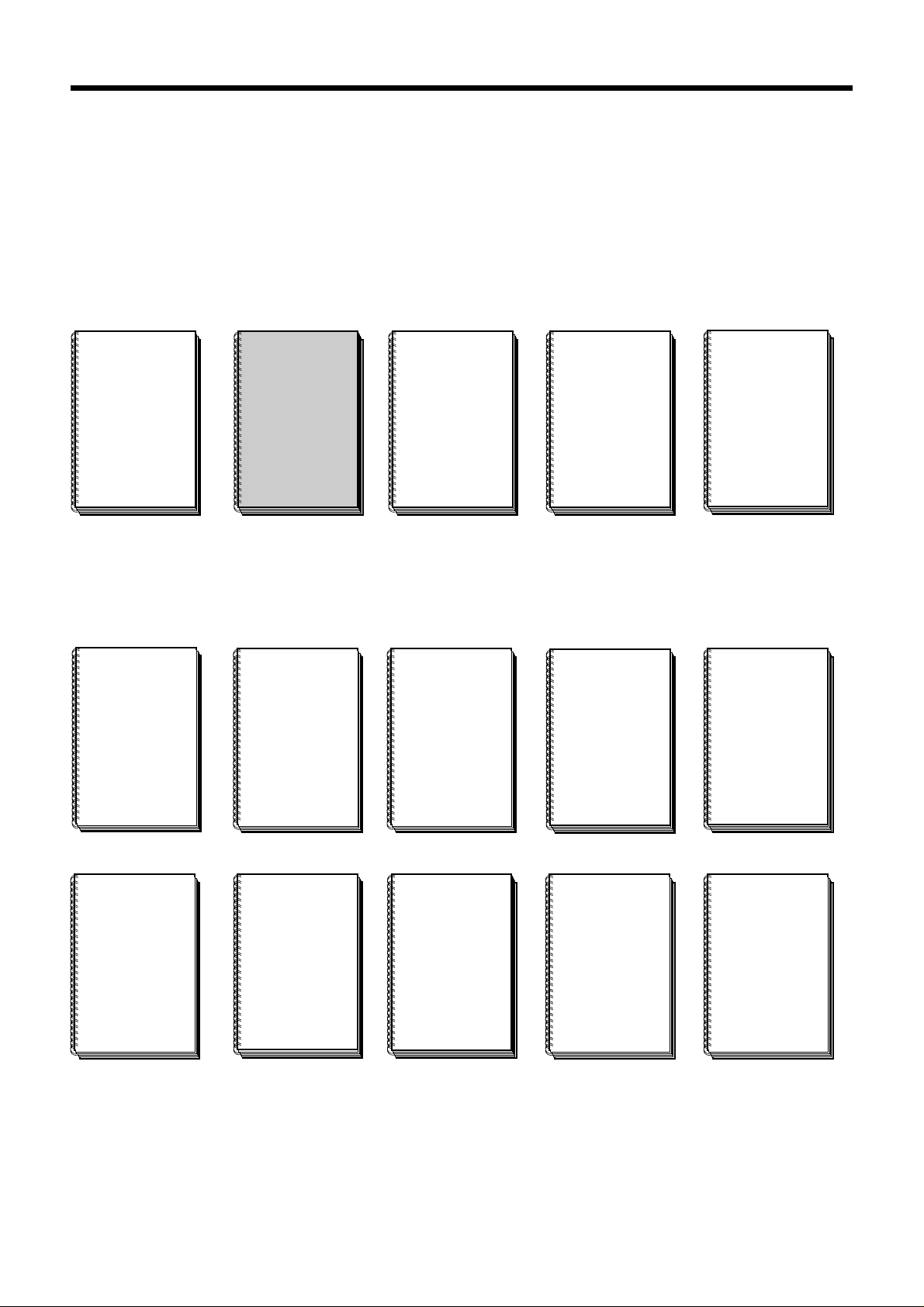
NUM 1020/1040/1050/1060 Documentation Structure
NUM T
PROGRAMMING
MANUAL
938820
NUM
PARAMETER
MANUAL
938818
User Documents
These documents are designed for use of the CNC.
Foreword
Foreword
NUM M/W
OPERATOR
MANUAL
938821
NUM T/G
OPERATOR
MANUAL
938822
NUM M
PROGRAMMING
MANUAL
938819
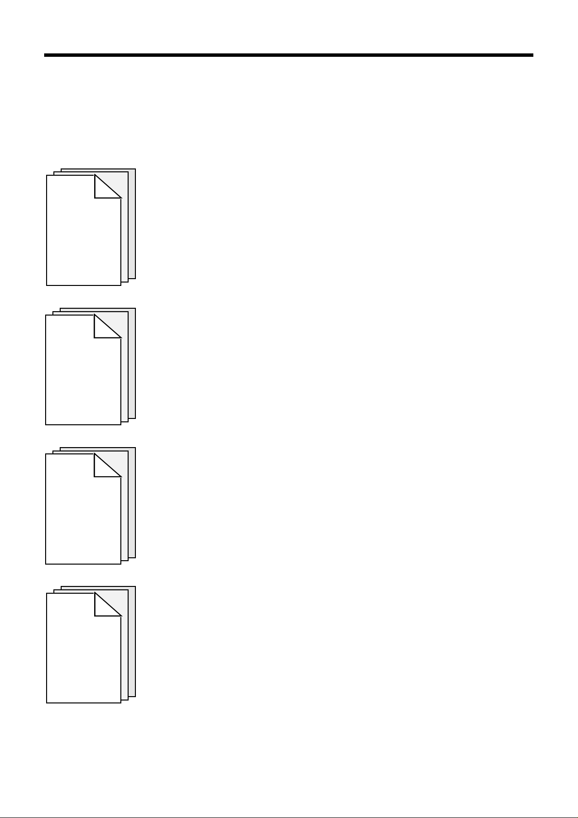
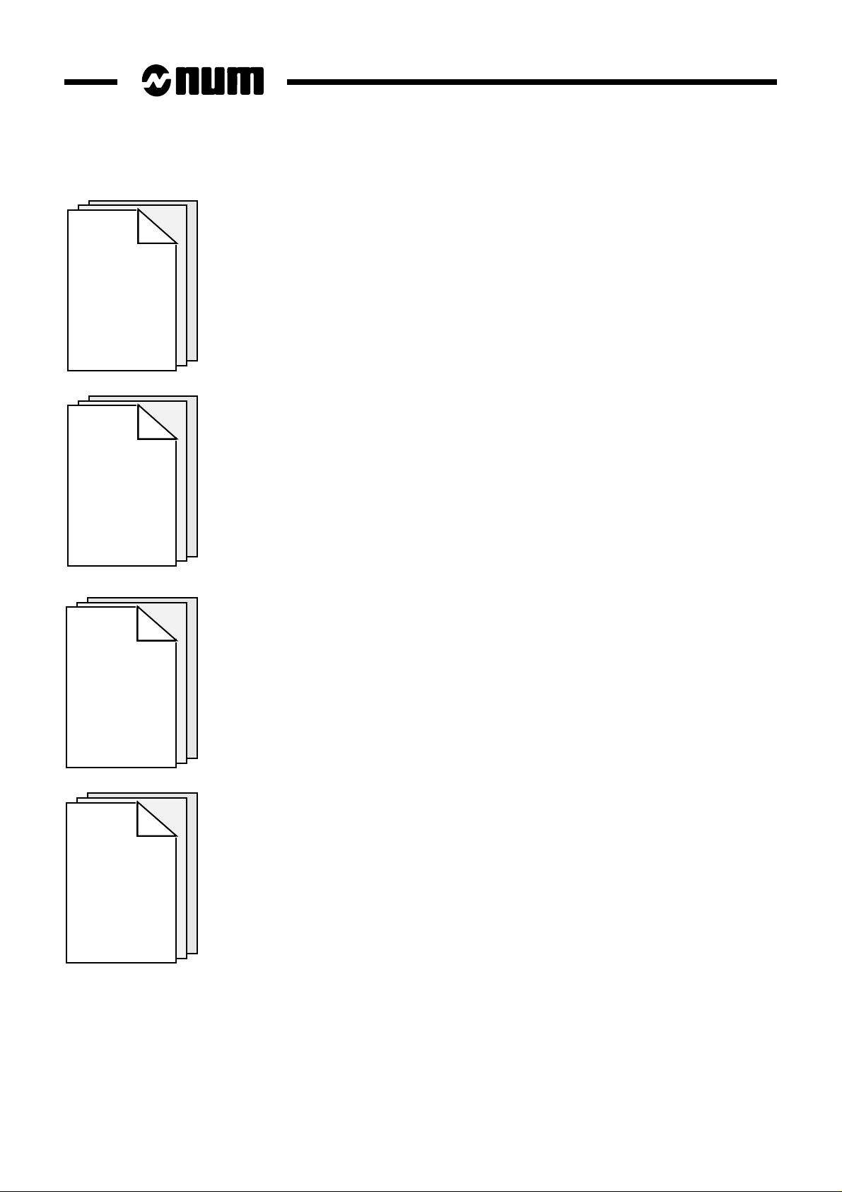
Integrator Documents
These documents are designed for setting up the CNC on a machine.
NUM 1060
INSTALLATION
AND
COMMISSIONING
MANUAL
938816
NUM 1020-1040
INSTALLATION
AND
COMMISSIONING
MANUAL
938938
NUM 1050
INSTALLATION
AND
COMMISSIONING
MANUAL
938977
NUM G
CYLINDRICAL
GRINDING
PROGRAMMING
MANUAL
938930
NUM
AUTOMATIC
CONTROL
FUNCTION
PROGRAMMING
MANUAL
LADDER
LANGUAGE
938846
MAN/MACHINE
INTERFACE
CUSTOMISATION
NUM
MMITOOL
TOOL
938946
NUM G
CYLINDRICAL
GRINDING
COMMISSIONING
MANUAL
938929
NUM
FTP40
PC PANEL
938967
NUM
SETTOOL
PARAMETER
INTEGRATION
TOOL
938924
NUM
PLCTOOL
LADDER
LANGUAGE
PROGRAMMING
TOOL
938859
en-938822/2 9

List of NUM Utilities
A series of utilities are available for products of the NUM 10xx range for integration and use of the system.
These utilities may be included in the basic version or available as options.
Depending on the function performed by each utility, its use is described in the integration manual or operator manual,
as appropriate.
The table below lists the utilities and gives the references of the document describing them:
Utility Name Manual
UT2 axis calibration installation and commissioning
manuals
UT3 resident macros operator manuals
UT5 parameter integration parameter manual
UT7 programme debugging machine processor programming
manual - ladder language
UT12 option locking operator manuals
UT20 interaxis calibration installation and commissioning
manual
UT22 parameter integration SETTOOL manual
10 en-938822/2
Operator Manual
CHAPTER 1
REVIEW
Foreword
Presentation of the CNC and its role in relation to the machine tool.
Reminder of the rules and standards associated with CNC and machines.
Overview of the relationship between the CNC and its environment.
CHAPTER 2
PRODUCT
PRESENTATION
CHAPTER 3
OPERATOR
PANEL
DESCRIPTION
Procedures for switching on and re-starting following an emergency stop.
Access to information about the system (job reference, customisation, etc.).
Detailed presentation of the operator panel and screen.
Use of special keyboard functions.
Detailed presentation of the CNC display pages.
CHAPTER 4
DISPLAY
SYSTEM
UTILIZATION
en-938822/2 11
CHAPTER 5
CNC
OPERATION
CHAPTER 6
OPERATIONAL
PROBLEMS
Description of machining preparation phases:
- axis jogs,
- machine-specific settings on the CNC,
- part programme processing.
Part programme automatic execution procedures.
Description of operator interventions during part machining.
Operations in background mode on part programmes.
Presentation of the incidents which occur most frequently on the CNC and flowcharts
indicating the most suitable action to be taken in each case.
Presentation of the system faults which can occur on power up and action to be taken.
CHAPTER 7
SYSTEM
FAULTS
CHAPTER 8
OPERATOR-
ACCESSIBLE
MAINTENANCE
Description of simple maintenance operations.
Presentation of user-accessible system management utilities.
12 en-938822/2
APPENDIX A
FUNCTION
SUMMARY
TABLES
APPENDIX B
Foreword
Introduction to part programming and tables summarising the programming functions
(all these notions are explained in detail in the Programming Manual).
List of CNC error numbers and descriptions.
LIST OF
ERRORS
APPENDIX C
USE OF
PERIPHERALS
APPENDIX D
INFORMATION
CONCERNING THE
EXCHANGE
AREA BIT
Presentation of peripheral commissioning operations prior to data exchanges.
Addresses of the exchange area bits mentioned in this manual.
en-938822/2 13

Using the Operator Manual
Procedures
This manual includes procedures.
The actions required are presented as follows:
Reset the system. ☞
The keys to be pressed are indicated on the right. They can have two forms:
Square keys: correspond to keys on the operator panel.
UTIL
Rectangular keys: correspond to softkeys located in the block at the bottom of the screen and activated
by function keys (F2-F11) located under the screen.
Y
Dealers
The list of NUM dealers is given at the end of the manual.
Questionnaire
To help us improve the quality of our documentation, we ask you to return the questionnaire at the end of this manual.
14 en-938822/2

Review
1 Review
1.1 System Overview 1 - 3
1.1.1 Overview of Modes 1 - 3
1.1.2 Defining a Programme 1 - 3
1.1.3 Preparing a Programme 1 - 4
1.2 Machine Overview 1 - 5
1.2.1 Review of Axis Definition and Direction 1 - 5
1.2.2 Machine Overview 1 - 6
1.2.3 Definition of Travels and Origins 1 - 7
1.2.4 Definition of Shifts 1 - 9
1.2.5 Definition of Tool Dimensions 1 - 12
1.2.5.1 Definition of Tool Reference Dimension 1 - 12
1.2.5.2 Definition of Tool Tip Radius and
Orientation 1 - 13
1.2.6 Definition of Tool Wear Offsets 1 - 14
1
en-938822/2 1 - 1

1 - 2 en-938822/2
Review
This chapter does not aim to reflect the way an operator actually uses his machine. Rather, it attempts to explain certain
basic notions which will be referred to in this manual.
For example, in paragraph 1.2.4 (definition of shifts), the aim is not to impose a method of measuring shifts, but simply
to provide a definition of shifts and the corresponding zero points.
1.1 System Overview
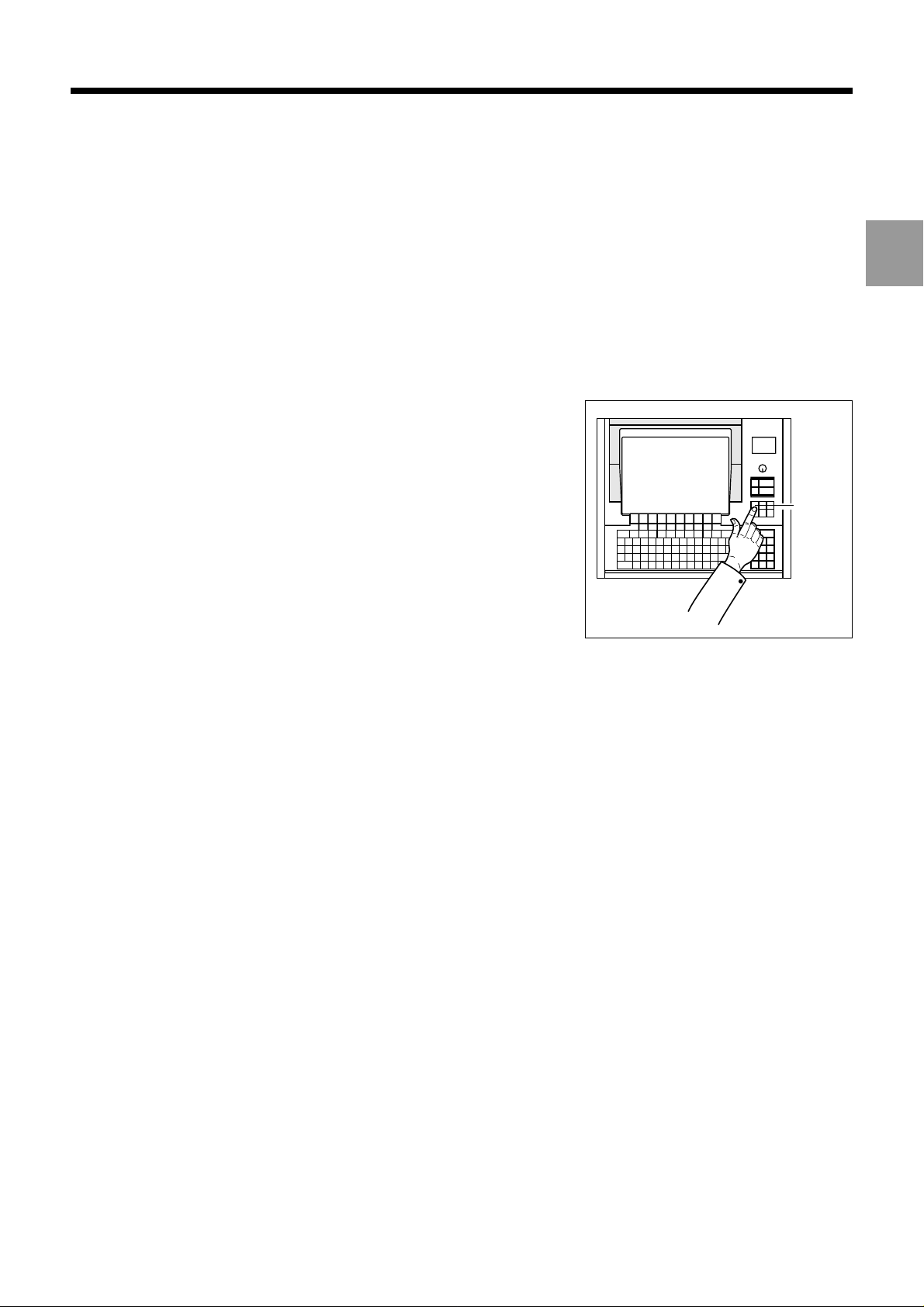
1.1.1 Overview of Modes
The operator uses the numerical control (NC) in various operating modes
accessible from the operator panel.
Each mode corresponds to a particular use of the numerical control
(continuous machining, programme loading, tool setting, etc.).
MODE
1
1.1.2 Defining a Programme
A programme is a sequence of instructions written in a programming language specific to the numerical control (the
most widely used is ISO code: International Standards Organization).
The numerical control interprets the programme to control actions on a machine-tool.
The most widespread storage media for programmes are punched tape and diskettes.
en-938822/2 1 - 3
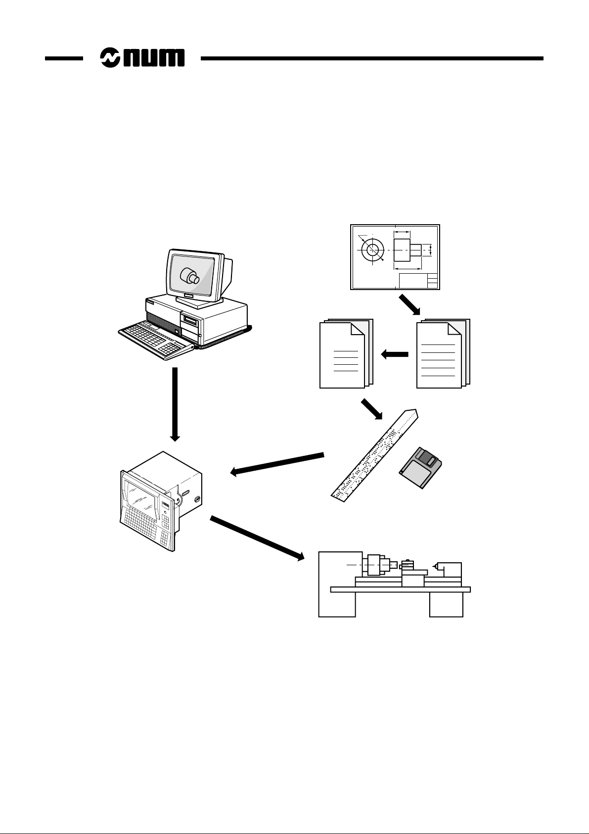
1.1.3 Preparing a Programme
A part programme can be created by traditional programming or using a CAD/CAM system.
CAD/CAM
Part
Programme
% 1
N10
N20
N30
Machining
instructions
1 - 4 en-938822/2

1.2 Machine Overview
1.2.1 Review of Axis Definition and Direction
A coordinate system is used to identify the positions and movements of an
object with respect to an origin or zero point.
A rectangular cartesian coordinate system is a right-handed three-axis
system of three linear axes, X, Y and Z, with which are associated three
rotary axes, A, B and C.
Review
1
Z
C
Y
B
The direction of axes X, Y and Z is easily remembered by the right-hand
rule.
The positive direction of rotation of a rotary axis corresponds to the
direction of screwing of a right-hand screw on the associated axis.
0
Z
X
A
Y
X
en-938822/2 1 - 5

1.2.2 Machine Overview
The manufacturer defines the coordinate system associated with the machine in accordance with standard ISO 841
(or NF Z68-020).
The X, Y and Z axes, parallel to the machine slideways, form a right-handed rectangular cartesian coordinate system.
The coordinate system measures tool movements with respect to the part to be machined, assumed fixed.
REMARK When it is the part that moves, it may be more convenient to identify its
movements. In this case, axes X’, Y’ and Z’, pointing in opposite directions from
axes X, Y and Z, are used.
The direction of the axis of a machine depends on the type of machine and the layout of its components.
For a lathe:
- the Z axis coincides with the spindle axis,
- the X axis is perpendicular to the Z axis and corresponds to radial movement of the tool-holder turret,
- the Y axis (generally fictional) forms a right-handed coordinate system with the X and Z axes.
Movement in the positive Z or X direction increases the distance between the part and the tool.
Rotary axes A, B and C define rotations around axes parallel to X, Y and Z.
Secondary linear axes U, V and W may or may not be parallel to primary axes X, Y and Z.
For more details, refer to the above-mentioned standard.
+ X
+ C'
+ Z
1 - 6 en-938822/2
Review
1.2.3 Definition of Travels and Origins
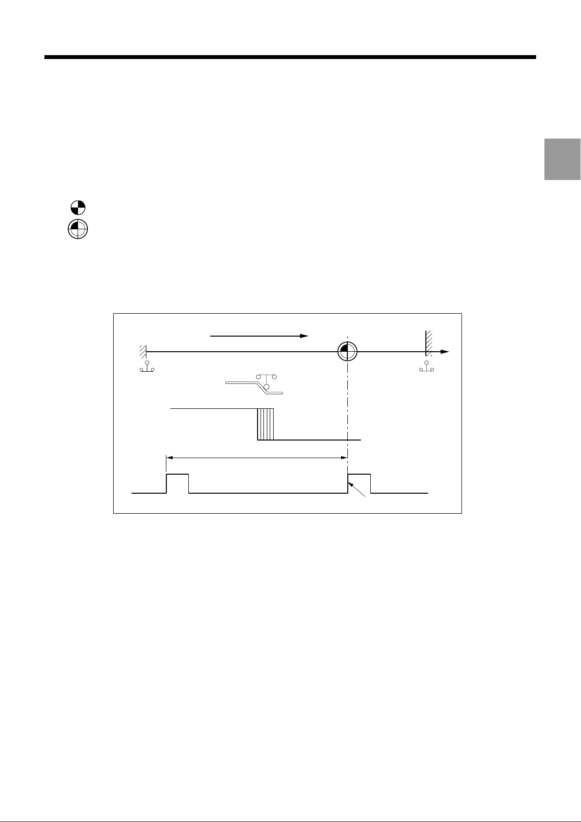
The NC processor computes all movements with respect to the measurement origin or zero point of the machine.
When the system is turned on, it does not know the measurement origin. The mechanical travel on each machine axis
is limited by maximum and minimum limit switches.
1
OM :
Om :
The homing procedure is completed for each of the axes when:
- the origin limit switch is actuated in the direction of movement specified by the m/c manufacturer (MOS direction),
- the encoder which measures axis movement outputs its marker pulse.
The system establishes the measurement origin (OM) via a homing procedure (MOS).
The home switch is set in a specific physical location: the machine zero point (Om) may or may not be the
same as the measurement origin (OM).
MOS direction
Om
Min. limit
switch
Contact closed Contact open
One encoder revolution
Max. limit
switch
Encoder marker pulse
en-938822/2 1 - 7
When homing (MOS) is completed, the system applies the shift defined by the manufacturer to each of the axes to
establish the measurement origin (OM).
Measurement origin shift (OM/Om) = ORPOM
The useful travel on each axis is established by software limits whose values are defined by the manufacturer.
X
Accessible
area
Origin switch
+ encoder
zero pulse
ORPOM X
OM
Mechanical travel on Z (limit switches)
Useful travel on Z
Om
ORPOM Z
Useful travel on X
Mechanical travel
Z
on X (limit switches)
1 - 8 en-938822/2
1.2.4 Definition of Shifts
To write a part programme, the programmer chooses a programme origin.
The programme origin is generally a starting point for dimensional measurements on the part drawing.
Review
1
OP :
Op :
It is possible to set the DAT1 and DAT2 values from the part programme.
Shifts on the Z axis
The operator sets the programme origin (OP) as shown below:
He sets (for each axis) a known, accessible point on the part, called the part origin (Op). This may be the
same point as the programme origin.
Part datum shift (Op/OM) = DAT1
Programme datum shift (OP/Op) = DAT2
Turret
Setting equipment
Z
Z
Measurement
origin
(OM)
OP
Z DAT2
Op
Turret
datum
Z DAT1
en-938822/2 1 - 9
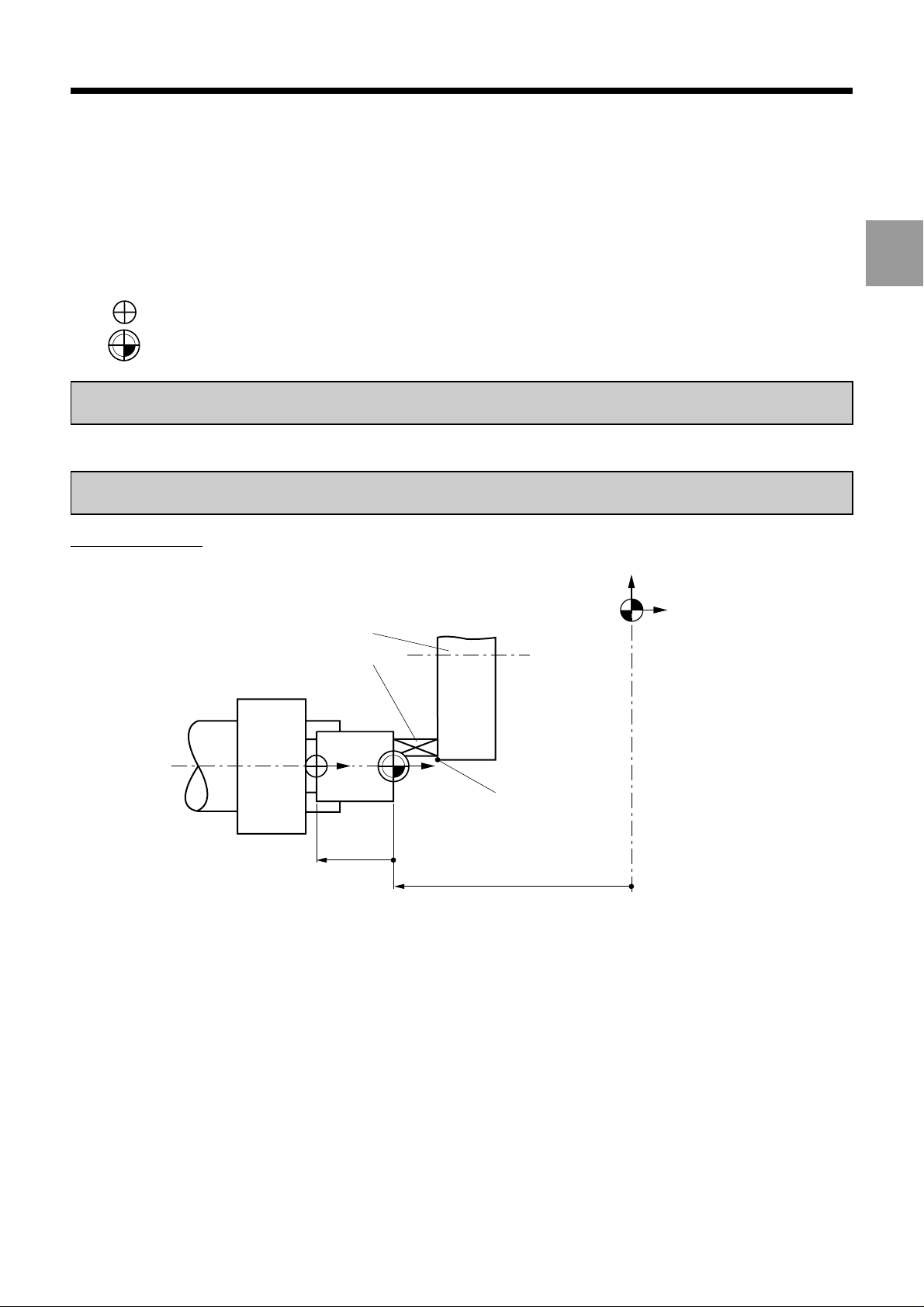
Shifts on the X axis
X
Turret
Turret
datum
Setting
equipment
X
Op
OP
Shifts on the X axis (solution without DAT2)
XDAT1: Fixed value measured between OM and the spindle axis.
Turret
Turret
datum
X DAT2
X DAT1
X
Measurement
origin
(OM)
Measurement
origin
(OM)
1 - 10 en-938822/2
X
OP
X
X DAT1
Op
Z

Review
The coordinates of any point (A) defined with respect to the programme origin (OP) are converted by the CNC into
coordinates with respect to the measurement origin (OM) :
1
X
OP
PART
Z DAT1
Z DAT2
Z
PA
Z
MA
Op
A
X
OM
MA
X
X
PA
Z
X DAT1
X DAT2
Z
Programme dimensions (with respect to OP) Measurement dimensions (with respect to OM)
X
PA
Z
PA
The dimensions are algebraic values.
Programmed shifts can be added to the programme dimensions.
XMA = XPA + X DAT1 + X DAT2
ZMA = ZPA + Z DAT1 + Z DAT2
en-938822/2 1 - 11

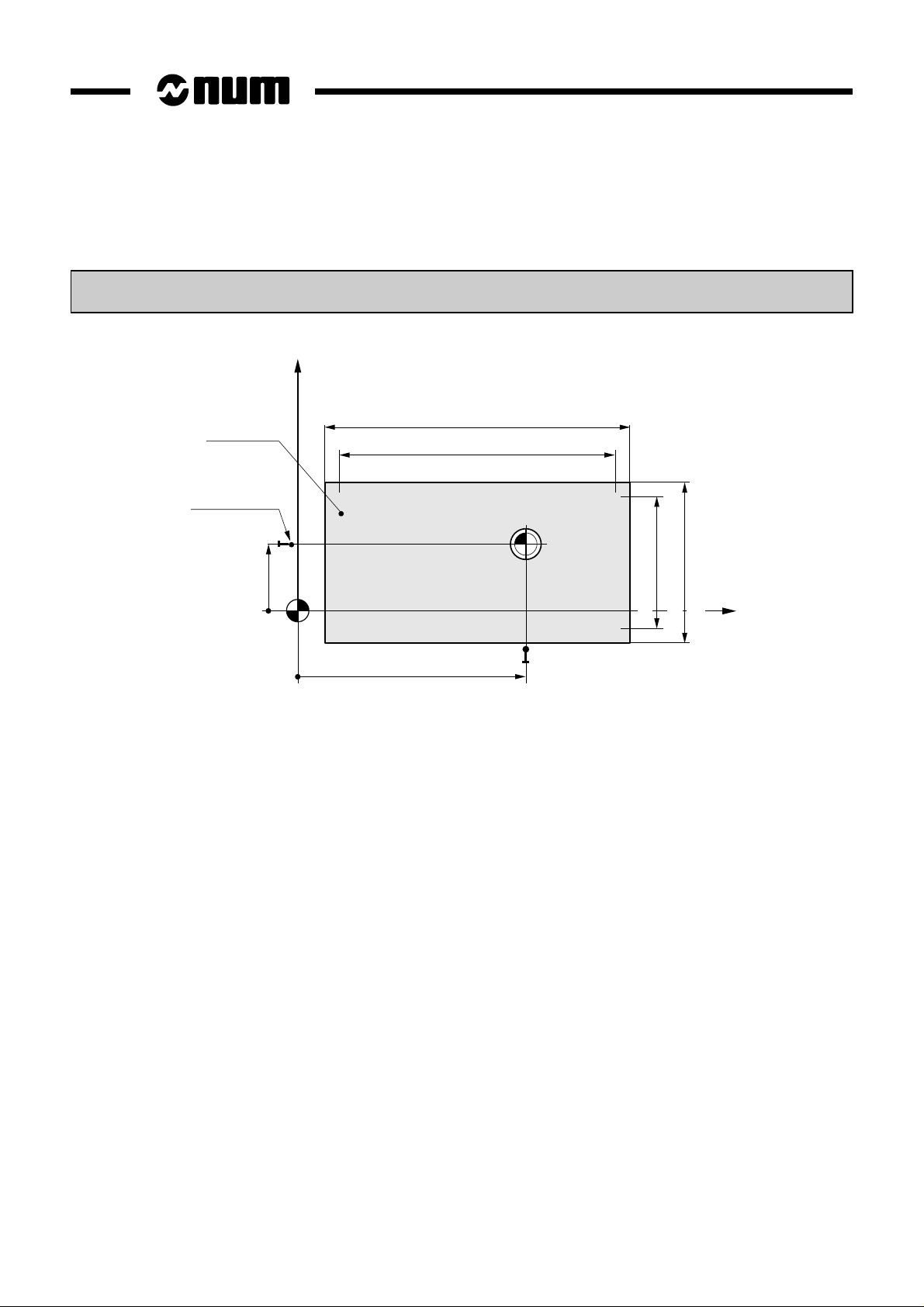
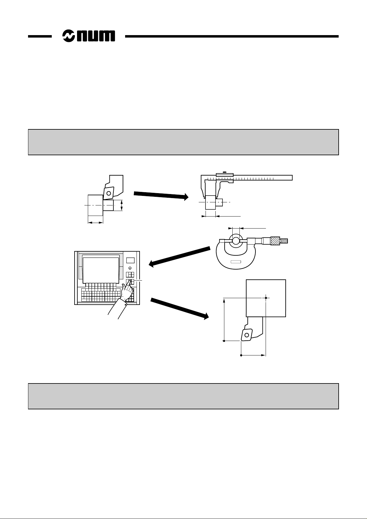
1.2.5 Definition of Tool Dimensions
1.2.5.1 Definition of Tool Reference Dimension
Tool reference dimension = distance from tool cutting edge to turret datum
X
OP
Turret datum
Part/tool
contact
diameter
X
Z
Tool axis orientation
OP
Z
Z dimension
Part/tool contact
surface
Turret datum
X dimension
1 - 12 en-938822/2
Tool X dimension = X
Tool Z dimension = Z
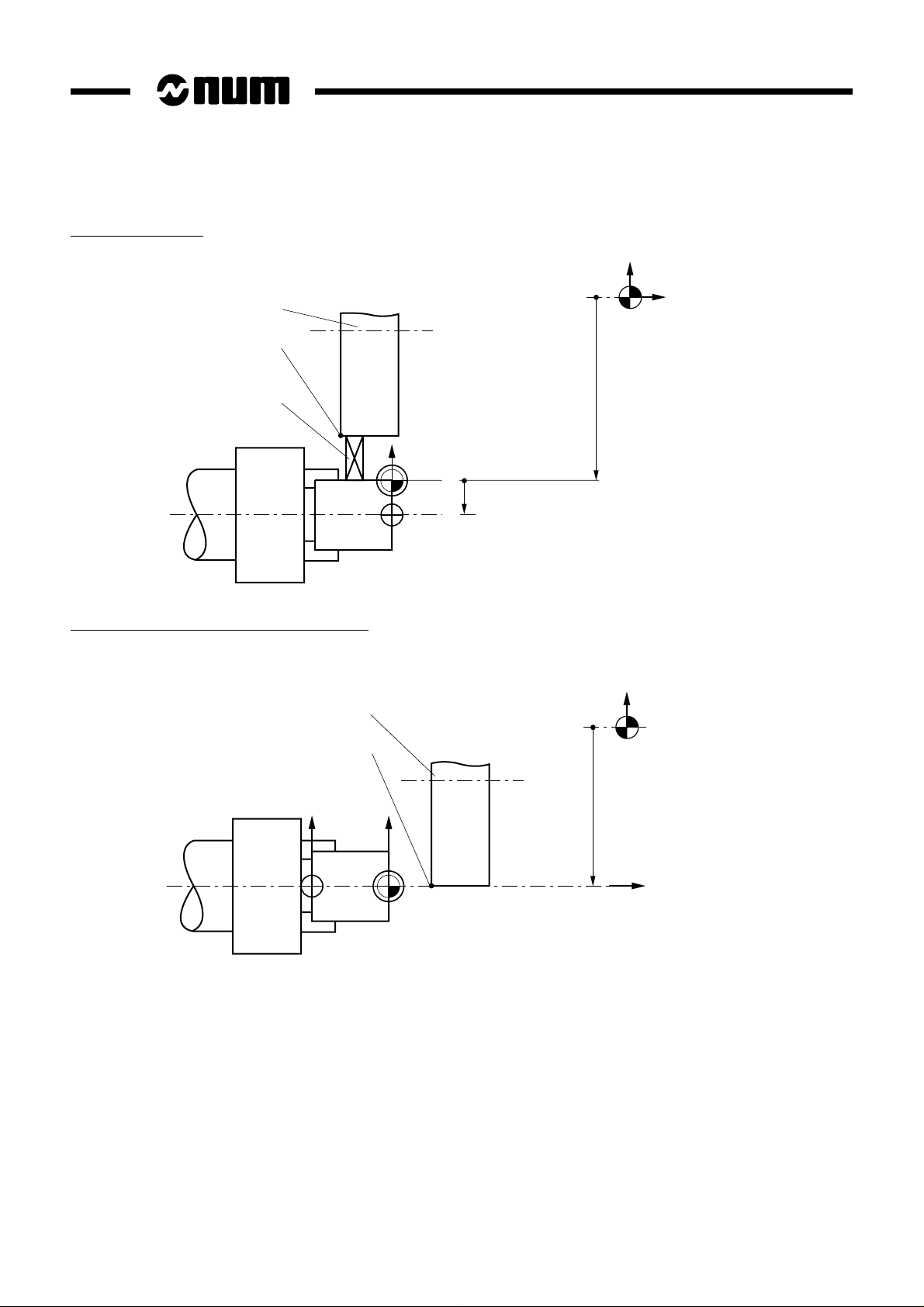
1.2.5.2 Definition of Tool Tip Radius and Orientation
Z
Z
X
P
P
C1
X
C4
Example:
C0 C8
C3 C2 C1
C5 C6 C7
The description of a tool is completed by:
Tool tip orientation = code C0 to C8
The tool tip orientation code allows the system to identify the location of
the tool cutting part centre (C) from the theoretical cutting point (P).
Review
1
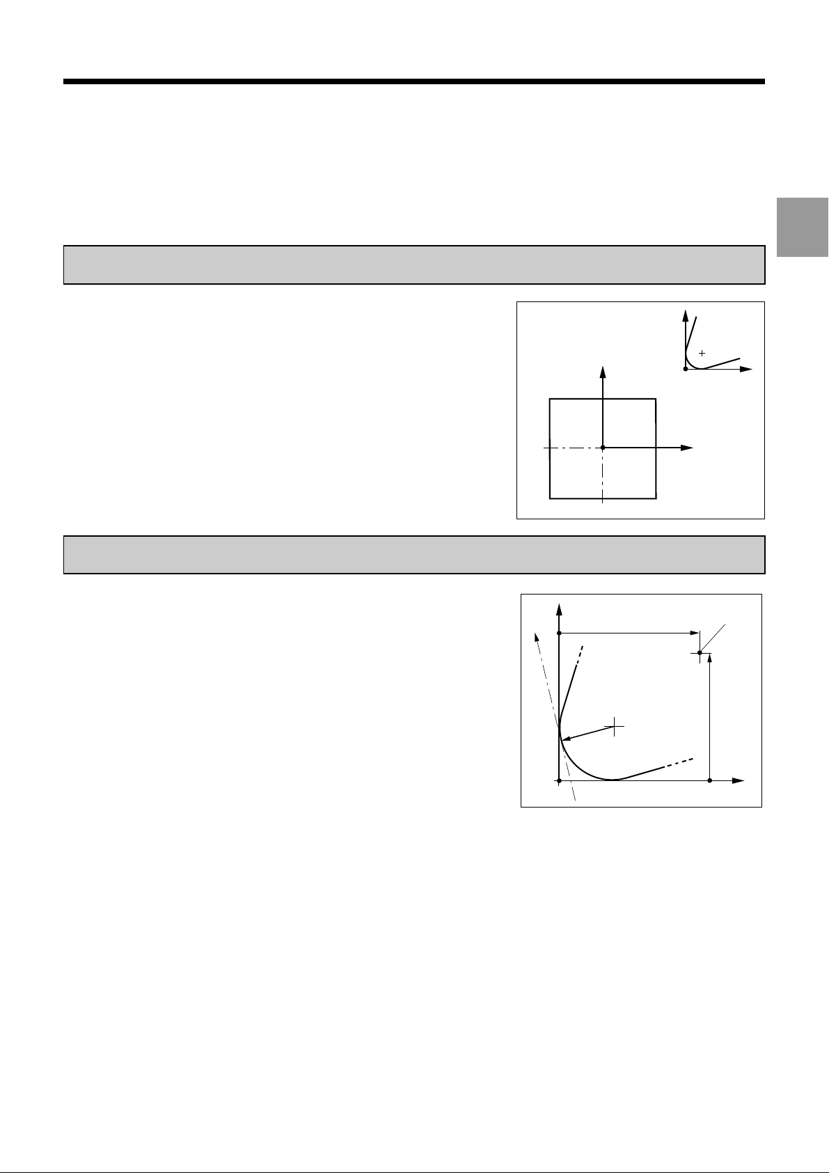
Radius of tool cutting part = R
The real tool cutting point is obtained by applying a vector with length «R»
perpendicular to the direction of movement starting from «C».
X
R
movement
Direction of
P
Z dimension
C
Turret
datum
X dimension
Z
en-938822/2 1 - 13
1.2.6 Definition of Tool Wear Offsets
At any time (even during machining), the operator can enter tool wear offsets when he observes a difference between
the expected and the actual results on a part.
The offsets (positive or negative) compensate for slight dimensional variations of the tool or part (wear, expansion).
Tool wear offset on X = DX (to the diameter)
D
L
Tool wear offset on Z = DZ
L + ∆L
D + ∆D
TOOL
DX = -∆D
DZ = -∆L
The system takes into account the corrected tool dimensions as quickly as possible:
Corrected length on X = X dimension + DX/2
Corrected length on Z = Z dimension + DZ
X + DX/2
Z + DZ
1 - 14 en-938822/2

Product Presentation
2 Product Presentation
2.1 Environment 2 - 3
2.1.1 NUM 1060 Series I or NUM 1060 Series II 2 - 3
2.1.2 NUM 1020, 1040 and 1050 2 - 4
2.1.2.1 NUM 1020, 1040 and 1050 with CNC Panel
or Compact Panel 2 - 4
2.1.2.2 NUM 1020, 1040 and 1050 with FTP40
PC Panel 2 - 5
2.2 Switching on/off 2 - 6
2.2.1 Switching on 2 - 6
2.2.2 Restart Following an Emergency Stop 2 - 6
2.3 System Identification 2 - 7
2.3.1 Access to System Customisation
Attributes 2 - 7
2.3.2 System Customization Information Grid 2 - 17
2
en-938822/2 2 - 1
 Loading...