

Page 1

NUM 1060
INST ALLATION AND
COMMISSIONING
MANUAL
0101938816/5-E1
10-97 en-938816/5-E1
Page 2

Despite the care taken in the preparation of this document, NUM cannot guarantee the accuracy of the information it contains and cannot be held
responsible for any errors therein, nor for any damage which might result from the use or application of the document.
The physical, technical and functional characteristics of the hardware and software products and the services described in this document are subject
to modification and cannot under any circumstances be regarded as contractual.
The programming examples described in this manual are intended for guidance only. They must be specially adapted before they can be used in
programs with an industrial application, according to the automated system used and the safety levels required.
© Copyright NUM 1997.
All rights reserved. No part of this manual may be copied or reproduced in any form or by any means whatsoever, including photographic or magnetic
processes. The transcription on an electronic machine of all or part of the contents is forbidden.
© Copyright NUM 1997 software CNC NUM 1060.
This software is the property of NUM. Each memorized copy of this software sold confers upon the purchaser a non-exclusive licence strictly limited
to the use of the said copy. No copy or other form of duplication of this product is authorized.
2 en-938816/5
Page 3

Table of contents
Table of contents
This executive summary includes only the level 1 and 2 titles. A complete table of contents is given at the beginning
of each chapter.
Part One: Installation
1 General Installation Instructions 1 - 1
1.1 Operating Conditions 1 - 3
1.2 System Power Consumption 1 - 4
1.3 System Cooling 1 - 5
1.4 Interconnections 1 - 6
1.5 Colours of the NUM 1060 Operator Panels 1 - 15
1.6 Screen Saver 1 - 15
2 General System Description 2 - 1
2.1 System Components 2 - 3
2.2 Basic Configuration 2 - 8
2.3 Multipanel Configuration 2 - 8
2.4 Multi-CNC Configuration 2 - 9
2.5 Multirack Configurations 2 - 9
2.6 System Architecture 2 - 10
3 Overall Dimensions - Installation 3 - 1
3.1 QWERTY 14" Colour Operator Panel 3 - 3
3.2 50-Key Panels 3 - 6
3.3 Compact Panel 3 - 12
3.4 Multiplexer Module 3 - 15
3.5 Card Racks 3 - 18
3.6 Machine Panel 3 - 24
3.7 Additional Components 3 - 26
4 System Component Preparation 4 - 1
4.1 Rack Preparation 4 - 3
4.2 Preparing the Compact Panel 4 - 12
4.3 Machine Panel Preparation 4 - 15
4.4 General Operations 4 - 20
5 Interconnections 5 - 1
5.1 CNC/Peripheral Interconnections 5 - 3
5.2 Operator Panel 5 - 8
5.3 Multiplexer Module 5 - 15
5.4 Rack Interconnections 5 - 16
5.5 Machine Panel Interconnections 5 - 22
5.6 NUM Diskette Drive 5 - 28
en-938816/5 3
Page 4

6 Cards 6 - 1
6.1 Power Supply Cards 6 - 5
6.2 1060 Series II CPU 6 - 7
6.3 1060 Series I Processor 6 - 11
6.4 CPU Cards 6 - 12
6.5 Incremental and Absolute Axis
Measurement Card 6 - 24
6.6 IT/Serial Line Card 6 - 32
6.7 Analogue Input/Output Card 6 - 34
6.8 32-24 I/O and 64-48 I/O Cards 6 - 36
6.9 32-Input/24-Output Card 6 - 42
6.10 32-Input Interface Modules 6 - 46
6.11 24-Output Relay Modules 6 - 50
6.12 32-Input Card 6 - 56
6.13 32-Output Card 6 - 59
7 Cables 7 - 1
7.1 Communication Cables 7 - 5
7.2 Axis Cables 7 - 17
7.3 Analogue I/O, Interrupt and Timer Cables 7 - 44
7.4 Input and Output Cables 7 - 56
7.5 Power Cables 7 - 72
7.6 Video Cable 7 - 76
Part Two: Commissioning
8 Initial Operation 8 - 1
9 Load and Check of the PLC Programme 9 - 1
9.1 Load Procedures 9 - 1
9.2 Checking the PLC Programme: Test of the
Safety Systems 9 - 1
10 Integration of the Machine Parameters (by UT5) 10 - 1
11 Axis Calibration (by UT2) 11 - 1
11.1 General 11 - 3
11.2 Record of Corrections to Be Made 11 - 5
11.3 Operations on Axis Measurement
Correction Tables 11 - 6
12 Interaxis Calibration 12 - 1
12.1 General Description of Interaxis
Calibration 12 - 3
12.2 Interaxis Calibration by Utility 20 12 - 7
12.3 Dynamic Interaxis Calibration 12 - 13
13 Final Inspection 13 - 1
4 en-938816/5
Page 5
Revisions of the Documentation
Date Index Description
12 - 91 0 Document creation
12 - 92 1 Inclusion of Series II
Inclusion of new components:
- 9" and 10" operator panels
- machine panel
- 2-slot extension rack
- 32-input interfacing module
- 24-output relay module
- IT card - Serial lines
Record of Revisions
03 - 94 2 Inclusion of the analogue 8-input/8-output card
Miscellaneous corrections
08 - 94 3 Inclusion of utility 20
Miscellaneous corrections
04 - 96 4 Inclusion of new components:
- version 2 machine processor
- UC SII CPU
- 32-24 and 64-48 I/O cards
- 32-input or 32-output cards with LMI connectors
- compact panel
- new 32-input interfacing module
- new 24-output relay module
- axis interface module
- NUM diskette drive
Inclusion of axes with absolute measurement
en-938816/5-E1 5
Page 6
Date Index Description
04 - 97 5 Inclusion of new components:
- version 2 CNC processor
- NUM keyboard
- 50-key keyboard with LCD screen
Improvement of existing components
Miscellaneous corrections and additional information.
10 - 97 5 - E1 Additional information on operating conditions
Modified cable shielding connection to connector plug covers
Modified multiplexer module mounting recommendations
Modified 50-key LCD panel power cable
6 en-938816/5-E1
Page 7
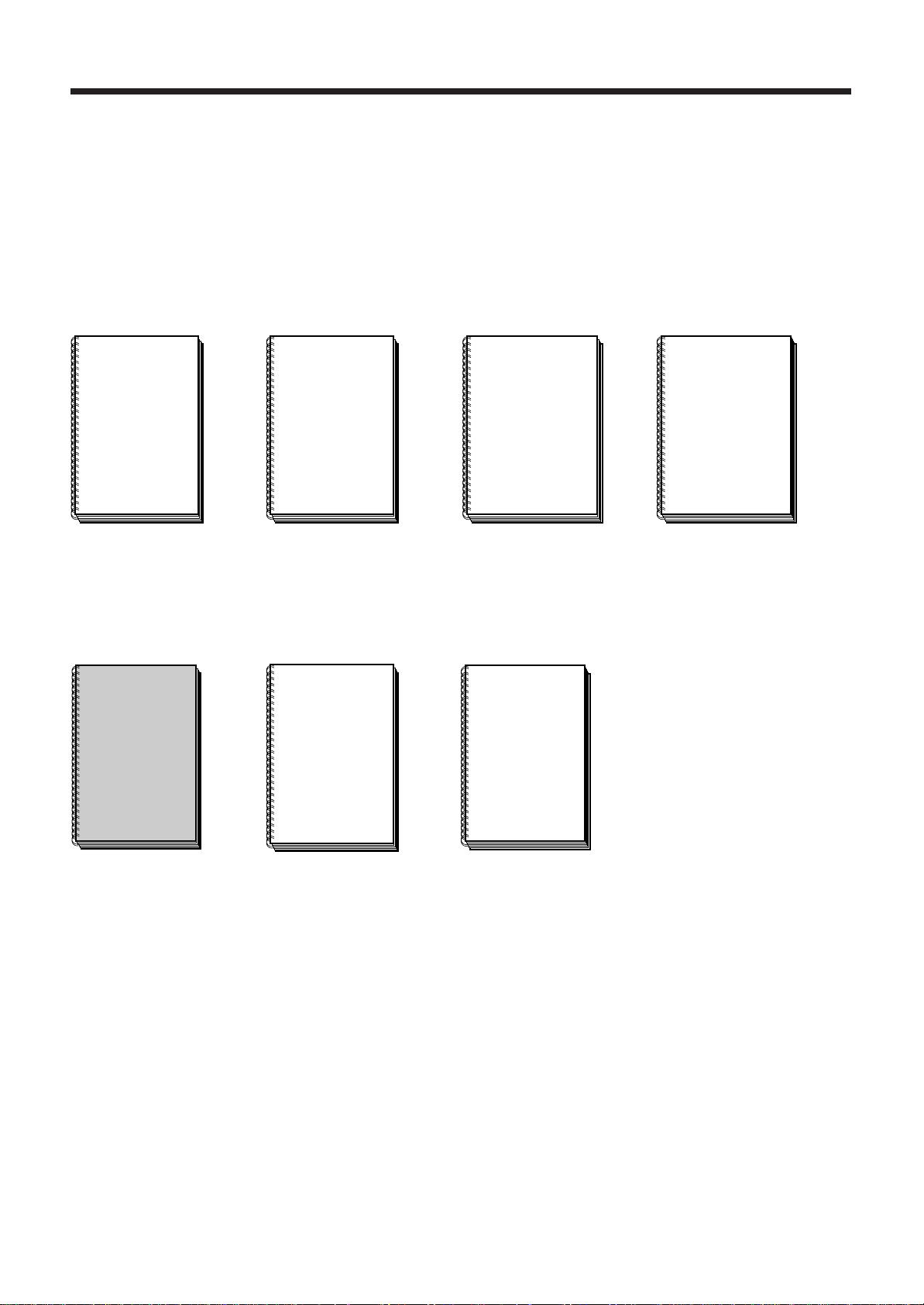
NUM 1060 Documentation Structure
User Documents
These documents are designed for use of the CNC.
Foreword
Foreword
NUM
OPERATOR
MANUAL
M / W
938821
NUM
OPERATOR
MANUAL
T / G
938822
NUM
PROGRAMMING
MANUAL
M
938819
Integrator Documents
These documents are designed for setting up the CNC on a machine.
NUM 1060
INSTALLATION
AND
COMMISSIONING
MANUAL
NUM
PARAMETER
MANUAL
NUM
AUTOMATIC
CONTROL
FUNCTION
PROGRAMMING
MANUAL
LADDER LANGUAGE
NUM
PROGRAMMING
MANUAL
T
938820
938816
938818
938846
en-938816/4 7
Page 8

List of NUM 1060 Utilities
A series of utilities are available for the NUM 1060 CNCs for integration and use of the systems.
These utilities may be included in the basic version or available as options.
Depending on the function performed by each utility, its use is described in the integration manual or operator manual,
as appropriate.
The table below lists the utilities and gives the references of the document describing them:
Utility Name Manual Chapter
UT2 axis calibration installation and commissioning manuals (938 816) 10
UT3 resident macros operator manuals (938 821 and 938 822) 8
UT5 parameter integration parameter manual (938 818) 12
UT7 programme debugging automatic control function programming manual - 16
Ladder Language (938 946)
UT12 option locking operator manuals (938 821 and 938 822) 8
UT20 interaxis calibration installation and commissioning manual (938 816) 11
UT22 integration of axis parameters SETTOOL Manual (938 924) 8
8 en-938816/4
Page 9
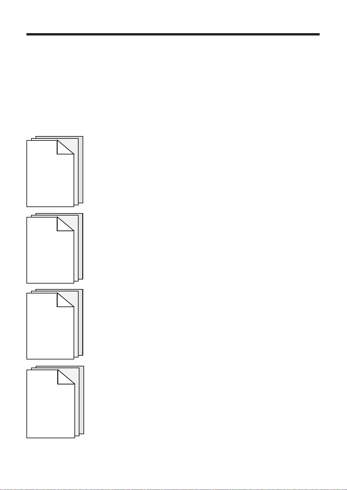
Installation and Commissioning Manual
This manual includes two parts:
- installation: physical integration of the numerical control with the machine and its environment,
- commissioning: adaptation of the CNC to the machine configuration.
Part One: Installation
General requirements concerning the CNC environment:
- operating conditions
- power consumption
Chapter 1
General
Installation
Instructions
- heat dissipation
- electrical specifications
- equipment colour.
Foreword
Chapter 2
General
System
Description
Chapter 3
Overall
Dimensions
—
Installation
Detailed explanation of the various possible configurations.
Overview of the system architecture.
Data used for installation of the components:
- detailed configuration
- overall dimensions
- mounting dimensions.
Card layout in racks.
Rack addresses.
Chapter 4
System
Component
Preparation
Temperature probe wiring.
Operations on the UC SII CPU.
Preparing the compact panel.
Preparing the machine panel.
Replacing fuses.
Wiring the watchdog.
en-938816/4 9
Page 10
Chapter 5
Interconnections
Chapter 6
Cards
Chapter 7
Cables
Wiring diagram for the different configurations.
General data and connections:
- CNC panels
- compact panel
- multiplex module
- racks
- machine panels
- NUM diskette drive.
General data and interconnection of the cards comprising the system.
Wiring diagrams for the following cables:
- communication
- axes
- analogue inputs/outputs, interrupts and timer
- inputs and outputs
- power supply
- video/panel.
10 en-938816/4
Page 11
Part Two: Commissioning
Chapter 8
Initial
Operation
Foreword
Initial operation procedure.
Reference to the PLC Function Programming Manual and checking instructions.
Specific features of the compact panel.
Chapter 9
Load and Check
of the PLC
Programme
Chapter 10
Integration
of the Machine
Parameters
Chapter 11
Axis
Calibration
Reference to the Parameter manual.
Correction of the axis position measurement read by the coupler according to the real
position on the axis.
en-938816/4 11
Page 12
Chapter 12
Interaxis
Calibration
Chapter 13
Final
Inspection
Correction of the offsets on a slave axis according to the position on a master axis.
Recommended inspection by machining of a reference part.
12 en-938816/4
Page 13

Use of the Installation and Commissioning Manual
Procedures
The manual includes procedures (in particular in Chapters 11 and 12).
The actions required are presented as follows:
Foreword
Reset the system. ☞
On the right are indicated the keys to be pressed in two possible forms:
Square keys: correspond to keys on the operator panel.
EXIT
Rectangular keys: correspond to software keys located in the bottom part of the screen and actuated
by function keys (F2-F11) located under the screen.
Y
Dealers
The list of NUM dealers is given at the end of the manual.
Questionnaire
To help us improve the quality of our documentation, we request you return to us the questionnaire at the end of this
manual.
en-938816/4 13
Page 14

14 en-938816/4
Page 15

Part One
INSTALLATION
Page 16

General Installation Instructions
1 General Installation Instructions
1.1 Operating Conditions 1 - 3
1.2 System Power Consumption 1 - 4
1.3 System Cooling 1 - 5
1.4 Interconnections 1 - 6
1.4.1 Mains 1 - 6
1.4.2 Protective and Signal Earth 1 - 6
1.4.3 Functional Earth 1 - 7
1.4.3.1 Equipment Operating at Relatively Low
Frequency and Low Signal Levels 1 - 7
1.4.3.2 Modern Equipment Operating at High
Frequency and High Signal Levels 1 - 8
1.4.4 Equipment Immunity 1 - 10
1.4.4.1 Reduction at the Source (interference
suppression) 1 - 10
1.4.4.2 Reduction of Couplings 1 - 11
1.4.4.3 Equipment Hardening 1 - 12
1.4.5 Diagram of the 0 V, Frame and Protective
Earth Links 1 - 13
1.5 Colours of the NUM 1060 Operator Panels 1 - 15
1.6 Screen Saver 1 - 15
1
en-938816/5 1 - 1
Page 17

1 - 2 en-938816/4
Page 18
General Installation Instructions
1.1 Operating Conditions
!
Do not unplug any subassemblies (cards, circuits) with the system live.
Do not solder the equipment when live.
Use earthed soldering irons.
Do not use testers with an output voltage ≥ 5 VDC.
NUM equipment complies with the following standards:
Reference standard Level
Temperatures IEC 1131
Mechanical stresses IEC1131
Mains variation IEC1131
Mains brownouts IEC1131
Electrostatic discharge (ESD) IEC 1000-4-2 Level 3
Electromagnetic field IEC 1000-4-3 Level 3 (excluding video)
Fast electric transients IEC 1000-4-4 Level 3
Electric shock IEC 1000-4-5 Level 3
IEC 1000-4-12
Electromagnetic emissions EN 55022
CAUTION
1
Operating temperature range: Minimum 5 °C, maximum 55 °C.
Cooling: See Sec. 1.3.
The systems must mandatorily be located in power cabinets equipped with:
- efficient door seals,
- air cleaners or air/air heat exchangers,
- possibly air-conditioning units.
en-938816/5-E1 1 - 3
Page 19
1.2 System Power Consumption
The system power consumption is calculated by adding the system component power consumptions.
Component Power consumption
CNC racks and cards (230 VAC)
• Power supply cards (includes rack consumption)
- 130 W power supply card 45 W
- 60 W power supply card 28 W
•Two-card extension rack 8 W
•CPUs
- UC SII CPU 11 W
- CNC/graphic processor 10.2 W
- graphic processor 10.2 W
- memory card 1.27 W
- machine processor 6.85 W
- version 2 CNC processor 5 W
-optional daughterboard for high-speed line 5 W
- version 1 CNC processor 5.55 W
•Axis card 6.85 W
•IT/serial line card 2 W
•Analogue I/O card 6.7 W
•Input/output cards
- 32/24 I/O card 4 W
- 64-48 I/O card 4 W
- 32-input/24-output card 4 W
- 32-input card 8.44 W
- 32-output card 6.4 W
Panels (230 VAC)
• QWERTY operator panel with 14" CRT 100 W
• 50-key or compact panel with 10" colour CRT 60 W
• 50-key or compact panel with 9" black and white CRT 30 W
50-key panel with LCD screen (24 VDC) 20 W (monitor)
Machine panels (24 VDC)
• Machine panel alone 3.8 W
• 32-input/24-output extension 9.8 W
Additional components (24 VDC)
• 32-input interface module 24 W
• 24-output relay module 19.2 W
• Multiplexer module 25 W
• NUM diskette drive 3.5 W
1 - 4 en-938816/5
Page 20
General Installation Instructions
1.3 System Cooling
!
The life cycle of electronic equipment is closely related to its operating temperature.
Compliance with the following recommendations will ensure optimal product reliability.
Determining the Air Flow Rate
The heat to be dissipated is at most 175 W for a rack and 100 W for the operator panel.
A more detailed calculation can be made by summing the individual power consumptions of the system components
(see 1.2).
CAUTION
1
The cabinet and pendant must be designed such that the temperature difference between the ambient air of the
components (CNC, CRT) and the ambient air in the shop is less than 10 °C or such that the average annual temperature
of the ambient air of the components does not exceed 40 °C.
The air flow rate required for correct heat dissipation is Q = 0.4 x P
where:
Q = air flow rate (l/s)
P = heat to be dissipated.
Example
For a 50-key panel with 10" colour CRT in a pendant:
P = 60 W
Q = 0.4 x 60 = 24 l/s.
REMARK This calculation should be confirmed by temperature measurements.
Recommendations
Use efficient filters on the cabinet or pendant air intakes.
Do not allow the fans to blow air directly onto the equipment.
en-938816/5 1 - 5
Page 21

1.4 Interconnections
1.4.1 Mains
Supply of the system by the single-phase 230 V mains does not require an isolation transformer but must:
- be independent of disturbed systems: connection as far upstream as possible on the general system, routing away
from power, high interference or low level cables,
- include the supervision, protection and cutout components specific to the system.
The installed power must be approximately twice the power rating (For the power consumptions of the system
components, see 1.2) to cater for transient overloads (peaks of around 10 times the rated value for a few cycles).
On mains that may be subject to interference such as:
- voltage or frequency variations,
- microbreaks due to mains equipment switching,
- power failures that are short (a few seconds) or long,
the installer must provide devices allowing the system to operate with in the limits defined by the tolerances.
Always earth the neutral of the 230 VAC power supply.
REMARK In the event of problems due to the mains, call in a specialised contractor authorised
to investigate the problem and recommend a suitable power supply source.
1.4.2 Protective and Signal Earth
Definition of the concepts of protective and signal earth:
- protective earth: low impedance, low frequency path between the circuit and earth used in the case of a fault,
- functional earth: low impedance path used between electric circuits for equipotentiality. The purpose of this earth
is the attenuation of all the spurious and accidental voltages that can exist between equipment items over a very
wide frequency band.
These two concepts do not correspond to different circuits.
The frame earth is provided by interconnecting all metal components (building structure, piping, cable trays, equipment
enclosures and equipment).
The earth is the physical connection (earthing well, earthing mat, building earthing system) to which the frame earth
must be connected.
1 - 6 en-938816/5
Page 22
1.4.3 Functional Earth
q
General Installation Instructions
A distinction is made between two types of electronic equipment:
- relatively low frequency equipment (a few kHz to a few hundred kHz) operating at low signal levels,
- equipment operating at high frequency (a few tens of MHz to a few hundred MHz) and high signal levels.
1.4.3.1 Equipment Operating at Relatively Low Frequency and Low Signal Levels
Such equipment mainly includes analogue systems sensitive to a few mV (or µV).
The most troublesome interference is generated by low and medium frequency electromagnetic fields injected in
particular in the loops between equipment items. High frequency interference is rejected by the natural bandwidth of
the circuit or by low-pass filters.
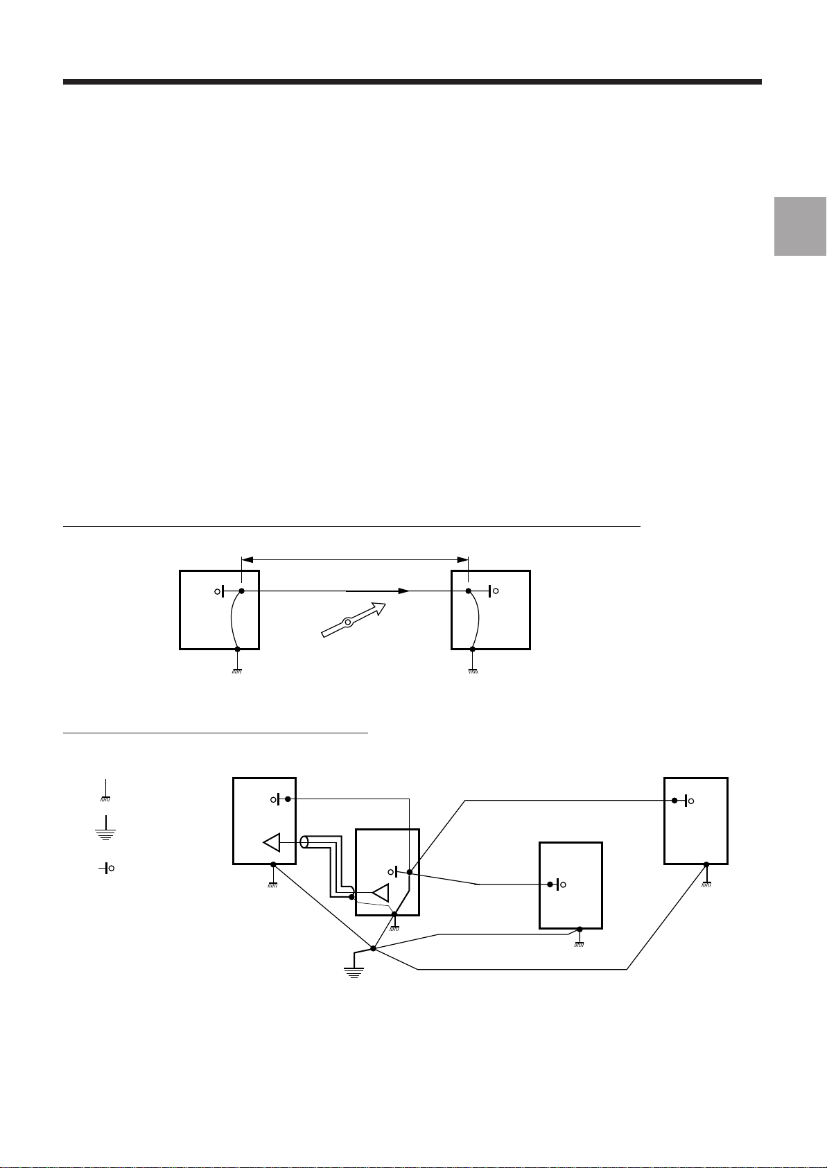
The following rules must be applied to decrease interference:
- star connection of the common circuits and star connection of the frame earth with a single interconnection between
the two systems,
- when a sensitive wire must be protected against electromagnetic interference by shielding, the shielding is
considered a screen and only one end is connected to the earth so as not to create a loop with an interference current
flow in the shielding.
Wrong: loops between equipment items due to interconnection of the earth and common wires
Voltage generated (U = ZI)
I : Current generated
A
B
AC
magnetic
field
Z: impedance
of link AB
1
uipment item 1 Equipment item 2
E
Right: star connection of earth and common wires
Equ. 1
: frame earth
: protective earth
: 0 V
Equ. 4
Equ. 2
Equ. 3
en-938816/4 1 - 7
Page 23

1.4.3.2 Modern Equipment Operating at High Frequency and High Signal Levels
Such equipment includes modern logic systems with electronic gates whose switching time are around 1 ns and whose
signal levels are high (static switching margin from 400 mV to 1 V).
The most critical interference is electromagnetic interference at frequencies between 30 and 300 MHz.
Such interference originates in all open coil circuits (relays, contactors, transformers, motors, transformer-driven
lights, etc.), arcing of circuit breakers when tripping, servo-drive switching devices, HF systems located nearby,
electrostatic discharges generated by the operators, etc.
At such frequencies, the earths must be equipotential. However, the impedance of an earthing wire is high at high
frequency (Z=Lω). For instance, for a 2.5 mm2 wire 1 metre long with an inductance L = 1.4 x 10⁻⁶ H, the impedance,
which is 0.09 Ω at 10 kHz, becomes 90 Ω at 10 MHz - and the earthing wires do not allow creation of a good frame
earth.
An "earth grid" is used to reduce interference: the equipment items are interconnected by the largest possible number
of links as short as possible.
This is best achieved by using metal parts interconnected by a large number of mounting points ensuring good
electrical conduction (zinc-plated or cadmium-plated steel, stainless steel, removal of paint, use of cleats on aluminum,
etc.).
If the electrical continuity is not sufficiently assured by the mechanical interfacing, the link must be shunted by at least
two short wide bonding braids (length/width ratio ≤ 5 and length < 20 cm).
1 - 8 en-938816/4
Page 24
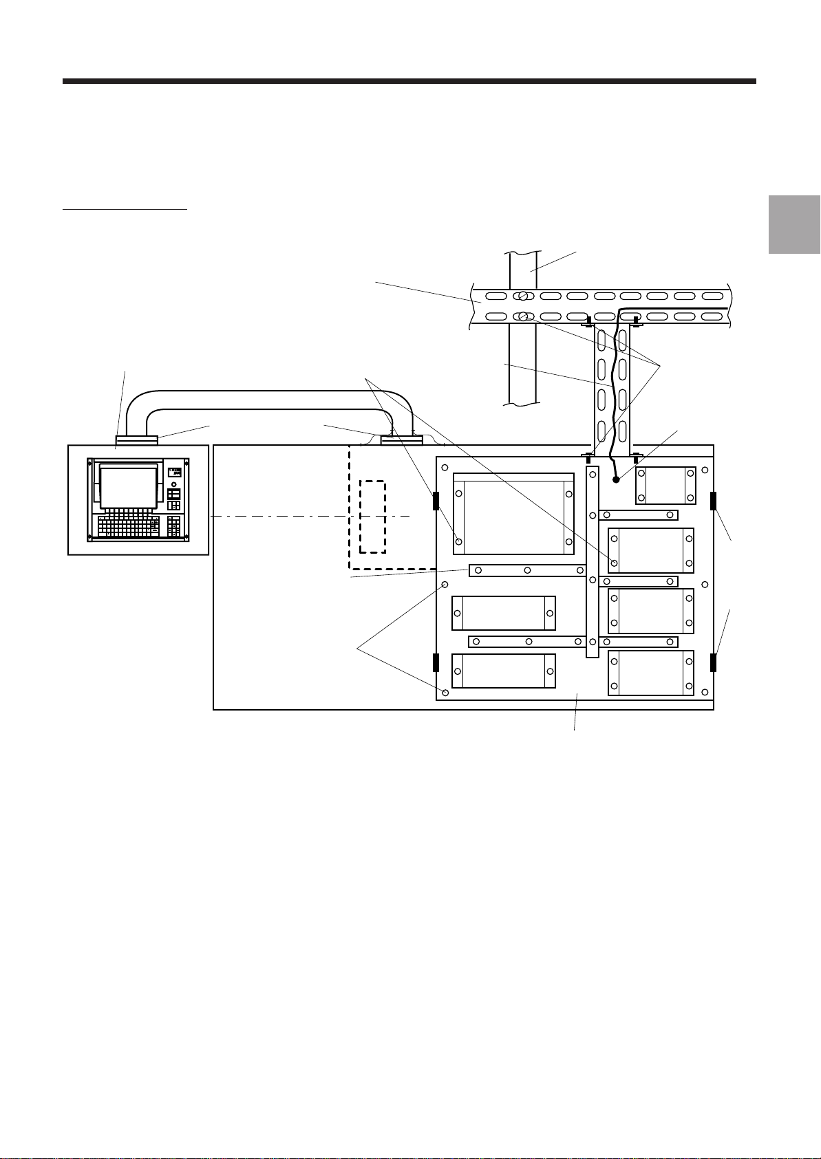
Example of Meshing
General Installation Instructions
NUM operator panel made
of zinc-plated steel
(to be mounted on a conductive
surface or connected by shunts)
Conductive seals
or 2 bonding braids
JOGTOOL
MODE
M01
HELP
F11 F12
F3F2
5^6&7*8(9)0_-+=+
S
x off
/
F10F9F8F7F6F5F4
{
[}]
:
`";
MNBVCXZSHIFT SPACE
,<.>/
line
line
DEL
INS
char
char
ALL
home Pg Up
CAPS
VALID
`
?
Pg Dnend
F1
!1@2#3$4%
ESC Q W E R T Y U I O P
CTRL A D F G HJKL
Pendant
Zinc- or cadmium-plated
metal cable trays
Metal frame equipment
with good electrical conduction
of the mounting points
Metal ducts
with conductive mounting
(recommended)
Cabinet mounting points
ensuring good
electrical conductivity
Protective
earthing wire
Earthing terminal
NUM CNC
RELAYS
RELAYS
Structural metal
building beam
Isolating
switch
Earth
DRIVE 1
DRIVE 2
DRIVE 3
Electrical continuity
provided
Earthing terminal
Door hinges
to be shunted
1
Metal power cabinet
Rear view of a lathe
The concepts of signal earth and protective earth coincide for the equipment, i.e. the logical 0 V is connected to the
frame earth in many points.
The logic circuit connecting cable shielding is earthed at both ends, which contributes to the mesh. In addition, the
internal electronics and the enclosure must be at the same potential.
To reduce the loop effects thus created (the field captured depends on the loop surface area), the cables must be
attached to ducts or metal surfaces. This type of wiring has a reductive effect "reductive effect".
In the case of separate power supplies for the logic inputs/outputs, the 0 V of these power supplies must be earthed
and the wiring must be made with "reductive effect".
REMARK The earthing grid is not a protective system. The earthing terminals of the equipment
items must be connected to the general system earthing terminal.
en-938816/4 1 - 9
Page 25
1.4.4 Equipment Immunity
EMI immunity of the equipment is achieved by:
- reducing the interference generated by the sources,
- reducing the couplings between source and circuit with interference,
- ensuring high immunity of the equipment.
The three approaches are complementary and are used simultaneously.
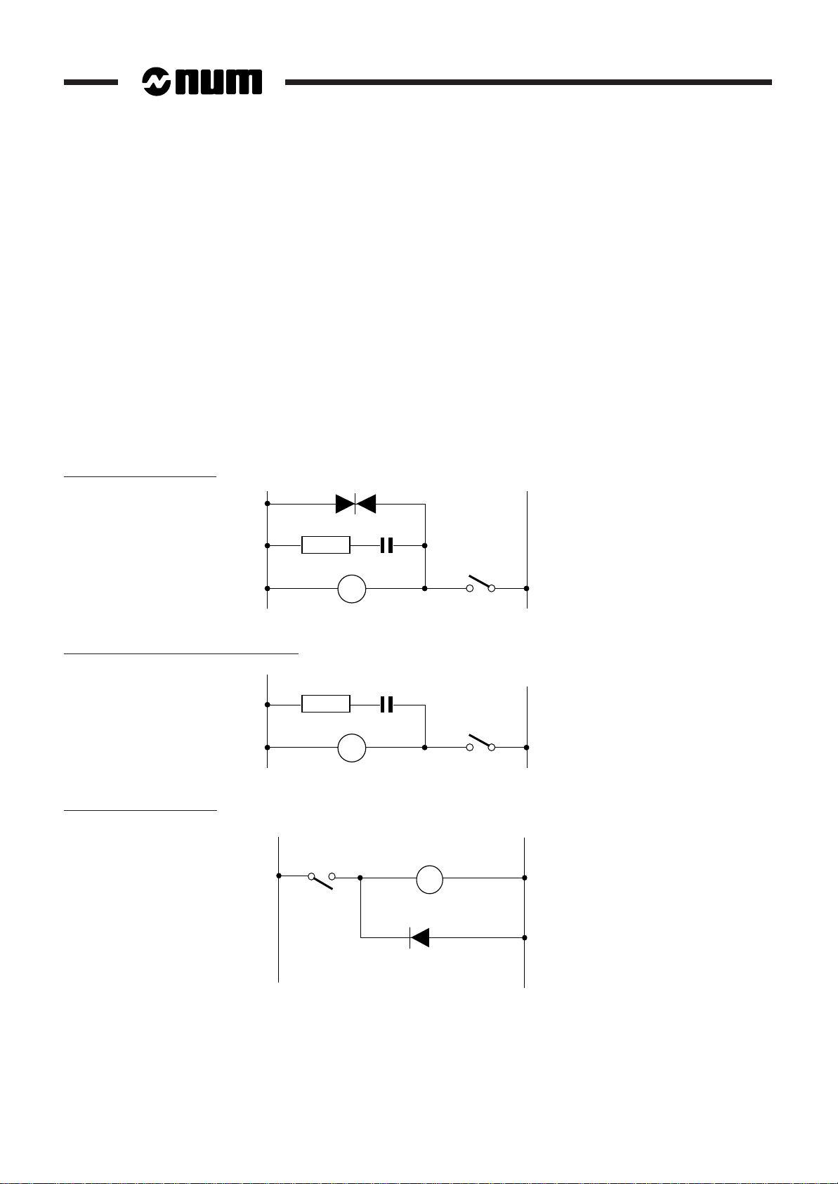
1.4.4.1 Reduction at the Source (interference suppression)
To limit the interference generated by components outside the system, make sure that:
- all the connections on terminal boards are tight,
- all the interference sources (relays, solenoid valves, motors, etc.) are provided with a suitable protection system.
Examples
Low power AC contactor
Medium and high power AC contactor
Low power DC contactor
+–
220 Ω
1W
0.47 µF
1 - 10 en-938816/4
Page 26
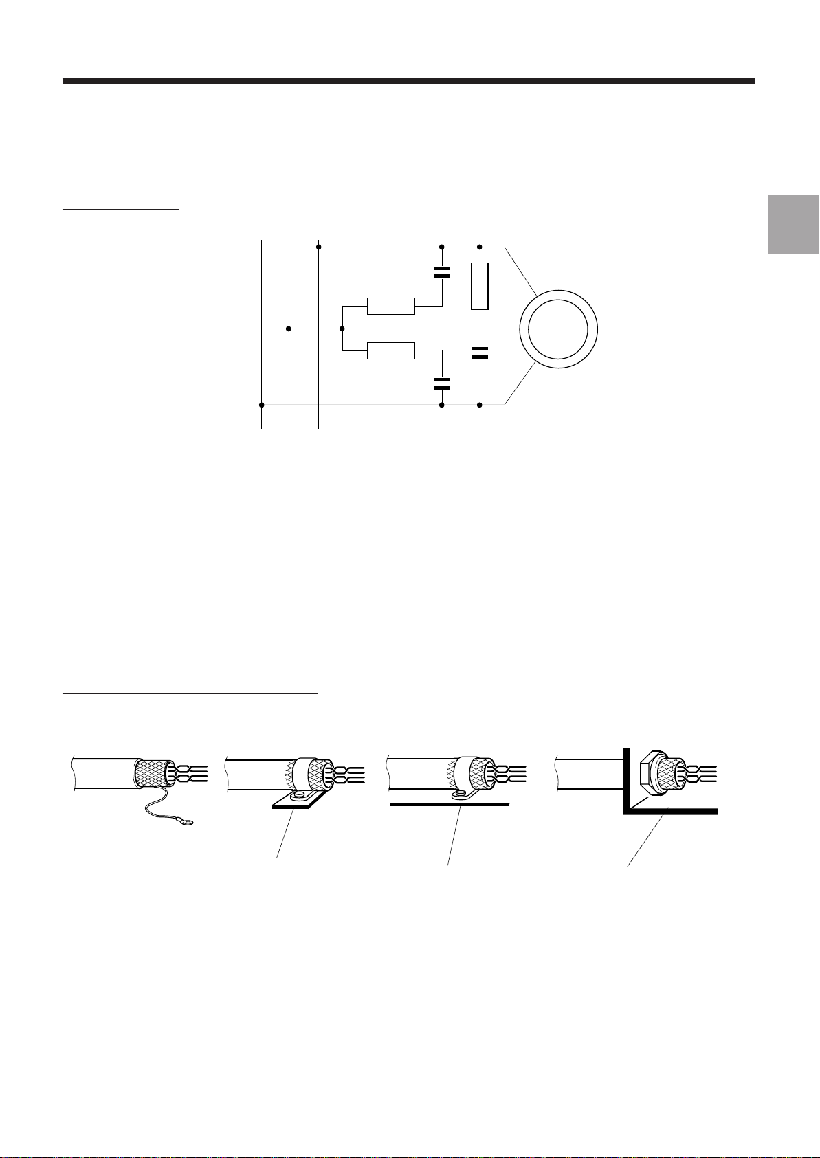
Three-phase motor
General Installation Instructions
1
M
1.4.4.2 Reduction of Couplings
For correct meshing of the earths (see 1.4.3.2), use metal cards with a conductive surface interconnected (bolted)
together.
Wire with a reductive effect (low surface area loops):
- cables applied against the ducts and metal parts forming the frame earth,
- signal forward and return path in the same cable (twisted pair).
Earth the shieldings of the logic signal cables at both ends.
Interconnect the cable shielding to the earth on 360 degrees:
- with a conductive gland to penetrate through a bulkhead,
- by pinching the shielding with metal covers themselves in contact with the earth for connector plugs.
Connection of a shielding to a frame earth
IDEAL 360-degree
PROHIBITED
ACCEPTABLE
Earthing
rail
CORRECT
Frame Frame
CONTACT
en-938816/4 1 - 11
Page 27
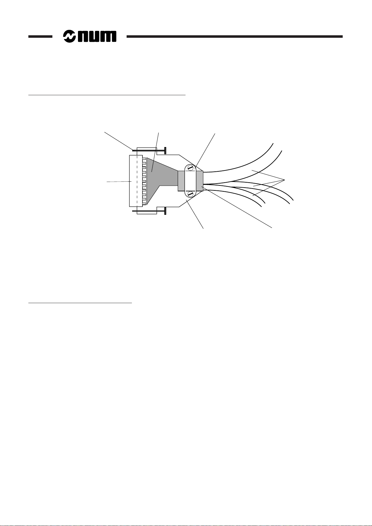
Interconnection of a Shielding to a Connector Plug Cover
Earth the cable shieldings over 360 degrees: fold the shieldings onto the cables over a length of 1 cm and clamp them
in the cover clamp.
Attachment
screw
SUB D
CONNECTOR
Separate the low-level cables from the power circuits or circuits with interference:
- by physical separation between the cables (at least 30 cm desirable),
- by routing in ducts with separate, distant cable trays,
- by 90-degree crossings.
The analogue inputs (for the servo-drives, for instance) must be differential (common mode rejection).
Particular Case of Servo-Drive Wiring
Location
of the wiring
Cable
clamp
Half-cover
Cables
Cable
shielding
The systems are low level (sensitive to microvolt levels) and low frequency. The link must therefore be protected by
a screen earthed on the CNC side only (see 1.4.3.1) and overshielding on the cable, earthed at both ends for the mesh.
When these recommendations are not applicable (unavailability of cables with double shielding, etc), preference shall
be given to the earthing mesh using a cable with single shielding earthed at both ends.
1.4.4.3 Equipment Hardening
This is related to the equipment design. Particular care was taken to ensure equipment immunity:
- multilayer cards with internal grounding plane,
- stainless steel enclosure of the system and front panels ensuring good contact with the enclosure, with the
assembly forming an excellent Faraday cage,
- metal connectors ensuring continuity with the front panels, provided with metal covers with 360 degree shielding
connection,
- high level of mains filtering at the power supply input,
- opto-isolated binary inputs/outputs with physical separation of circuits with interference.
All these measures make the equipment highly resistant to electromagnetic interference.
1 - 12 en-938816/5-E1
Page 28
General Installation Instructions
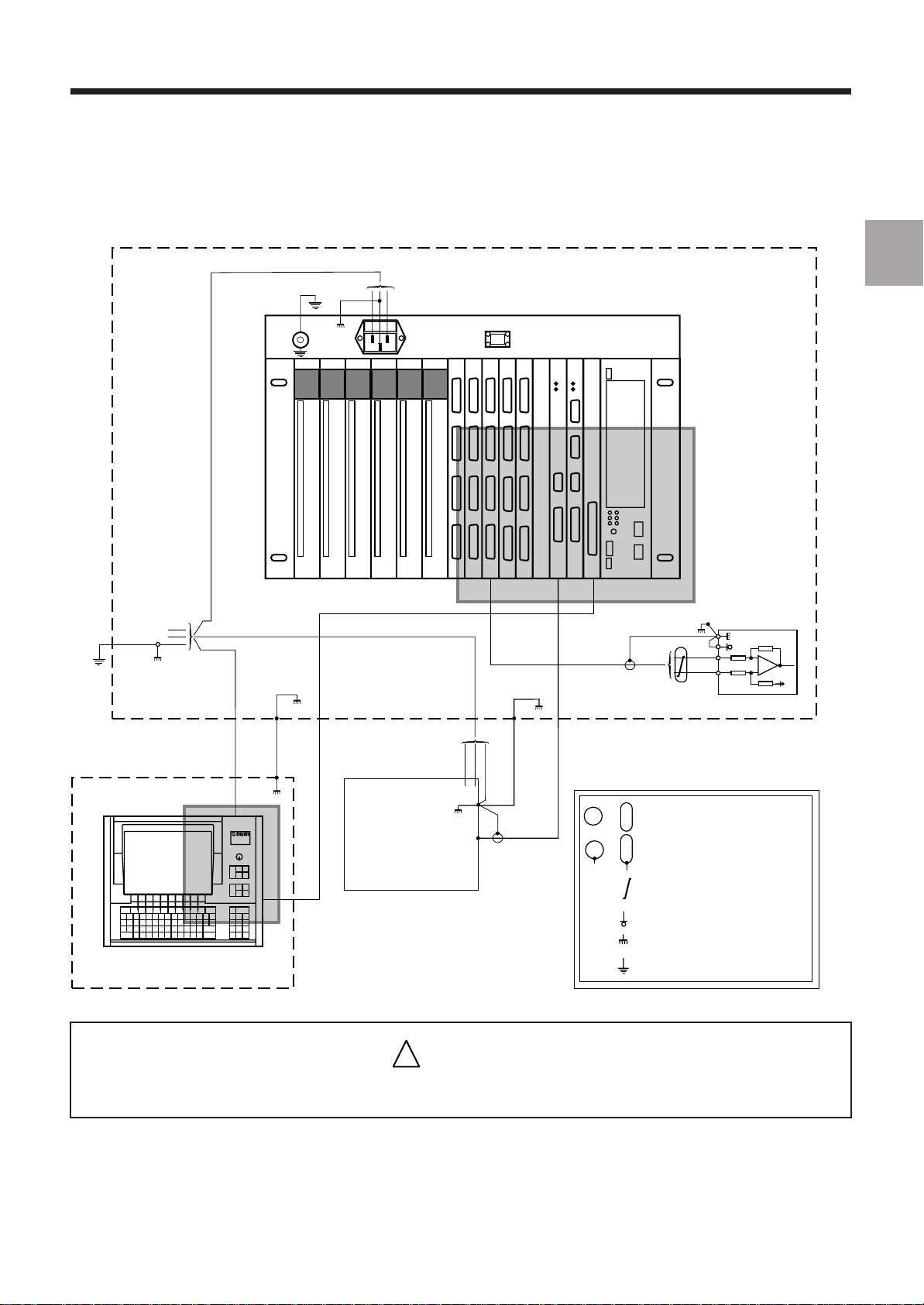
1.4.5 Diagram of the 0 V, Frame and Protective Earth Links
230 VAC
VIDEO/OPERATOR PANEL
AXES
Shielding
SEE DETAIL 2
Screening
(not compulsory)
POWER CABINET
SERVO-DRIVE
Axis or Spindle
1
SEE DETAIL 1
PENDANT
STORAGE UNIT
!
CAUTION
LEGEND
PERIPHERAL
or
or
Shielding not connected at this end
Shielding connected at this end
Twisted wires
0 V
Frame earth
Protective earth
The 0 V of the 24 VDC power supplies must mandatorily be connected to the frame earth
en-938816/5 1 - 13
Page 29
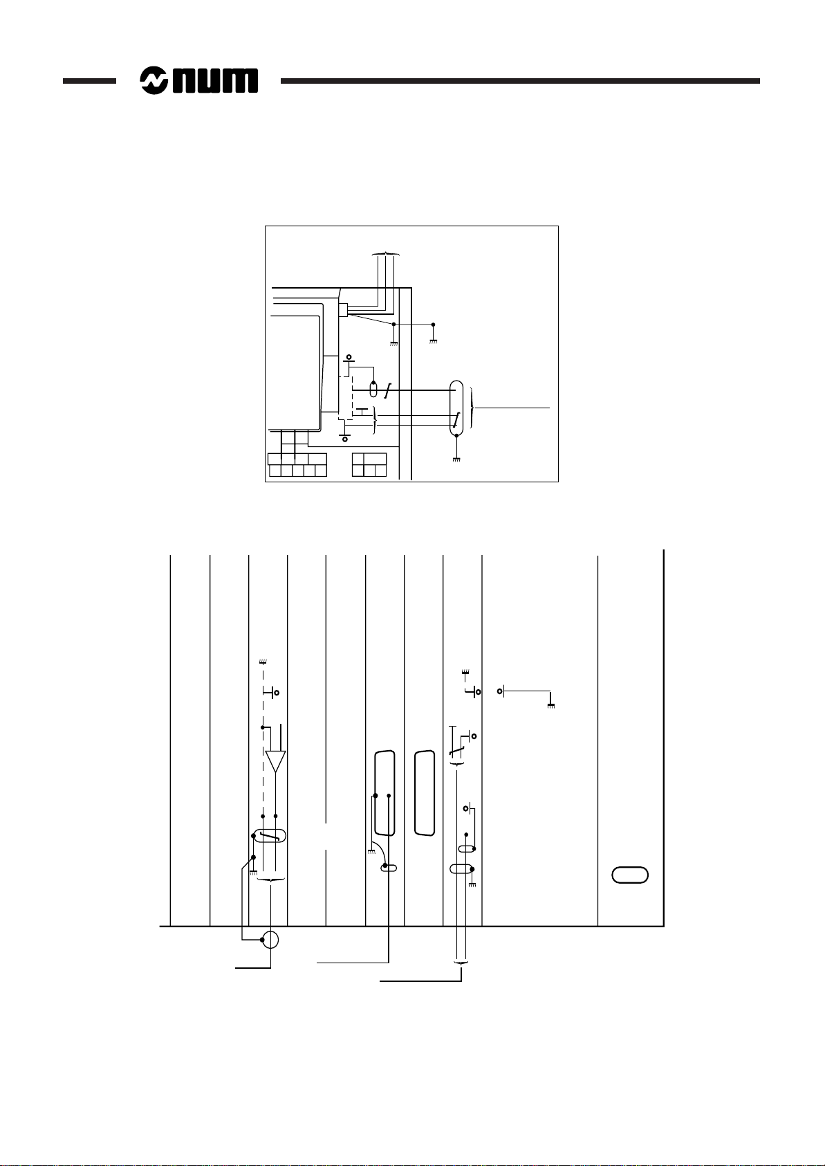
Detail 1
230 VAC
Detail 2
Axis card
Op. panel
5V
Operator panel
Graphic display
processor
CNC processor or
machine processor card
5V
Video /
1 - 14 en-938816/4
Axes
Screening
not compulsory
Power supply
Shielding
Peripheral
Video / Operator
panel
Page 30

General Installation Instructions
1.5 Colours of the NUM 1060 Operator Panels
The colours used on the NUM 1060 operator panels are standard colours:
Colour Used on Standard
Dark grey Background RAL 7021
Medium grey Keys RAL 7036
Light grey Keys RAL 7032
Red Side trim PANTONE WARM RED C
1.6 Screen Saver
The CNC has a screen saver system designed to extend the screen life. When the screen saver is activated by the
PLC programme, it turns off the screen after five minutes of keyboard inactivity. Pressing any key redisplays the
previously active page.
1
It is recommended to activate the screen saver by the PLC programme. This is done by setting bit SC_SAVE (%W5.7).
en-938816/4 1 - 15
Page 31

1 - 16 en-938816/4
Page 32

General System Description
2 General System Description
2.1 System Components 2 - 3
2.1.1 Operator Panel 2 - 3
2.1.1.1 QWERTY Operator Panel 2 - 3
2.1.1.2 50-Key Panel 2 - 3
2.1.1.3 Compact Panels 2 - 4
2.1.2 Main Rack 2 - 4
2.1.3 Extension Racks 2 - 5
2.1.4 Machine Panel 2 - 5
2.1.5 Additional Components 2 - 6
2.2 Basic Configuration 2 - 8
2.3 Multipanel Configuration 2 - 8
2.4 Multi-CNC Configuration 2 - 9
2.5 Multirack Configurations 2 - 9
2.6 System Architecture 2 - 10
2.6.1 1060 Series II System 2 - 10
2.6.1.1 1060 Series II with Biprocessor 2 - 10
2.6.1.2 1060 Series II with UC SII Processor 2 - 11
2.6.2 1060 Series I System 2 - 12
2
en-938816/5 2 - 1
Page 33

2 - 2 en-938816/5
Page 34

2.1 System Components
2.1.1 Operator Panel
2.1.1.1 QWERTY Operator Panel
14" Colour Operator Panel
Subassemblies Weight (kg)
Operator panel 16.5
Câble vidéo
General System Description
2
2.1.1.2 50-Key Panel
10" Colour and 9" Monochrome Operator Panels
Subassemblies Weight (kg)
Operator panel 10.7
Video cable
Panel with LCD Display
Subassemblies Weight (kg)
Monitor 3.6
Keyboard 2.1
Video and keyboard cables
en-938816/5 2 - 3
Page 35

2.1.1.3 Compact Panels
10" colour and 9" monochrome compact panels
Subassemblies Weight (kg)
Operator panel 11
Video cable
2.1.2 Main Rack
The main rack is available in two versions:
1060 Series II Rack
Subassemblies Configuration Weight (kg)
12" single rack (or 19") 4.920
60 W power supply card 1.870
or 130 W power supply card 2.130
UC SII CPU (two CNC card slots) 0.780
Biprocessor CPU Graphic/CNC processor 0.360
(three CNC card slots) Machine processor 0.390
CNC cards Axis cards 0.310
Input/output cards 32-input/24-output cards 0.340
Memory card 0.460
Special interfaces
64-48 or 32-24 I/O card
2 - 4 en-938816/5
1060 Series I Rack
Subassemblies Configuration Weight (kg)
19" single rack (or 12") 6.800
60 W power supply card 1.870
or 130 W power supply card 2.130
CNC cards Graphic processor 0.360
Machine processor 0.390
CNC processor 0.315
Memory card 0.460
Axis cards 0.310
Special interfaces
Input/output cards 32-input cards 0.295
32-output cards 0.490
32-input/24-output cards 0.340
64-48 or 32-24 I/O card
Page 36

General System Description
The table below gives the maximum number of input/output cards according to the number of slots occupied by CNC
cards in a 12" rack:
Number of CNC cards 4 5 6 or 7
Number of input/
output cards 4 3 2
The table below gives the maximum number of input/output cards according to the number of slots occupied by CNC
cards in a 19" rack:
Number of CNC cards 5 or 6 7 8 or 9 10 11 or 12 13 14 or 15
Number of input/
output cards 8765432
2.1.3 Extension Racks
Two types of extension racks are available:
2
12-Slot Extension Racks
Subassemblies Weight (kg)
12-slot rack 6.800
130 W power supply card 2.130
Fibre-optic connecting cables
Input/output cards 32-intput card (maximum 8) 0.295
(3 to 12) 32-output card (maximum 8) 0.490
32-input/24-output cards 0.340
64-48 or 32-24 I/O card
2-Slot Extension Racks
Subassemblies Weight (kg)
2-slot extension rack (including power supply) 2.140
Fibre-optic connecting cables
Input/output cards 32-input card 0.295
(1 or 2) 32-output card 0.490
32-input/24-output cards 0.340
64-48 or 32-24 I/O card
2.1.4 Machine Panel
Subassemblies Weight (kg)
Machine panel 2.200
Fibre-optic cables
Machine panel extension (optional) 0.300
Handwheel (optional) 0.515
en-938816/5 2 - 5
Page 37

2.1.5 Additional Components
32-Input Interfacing Modul
Subassemblies Weight (kg)
Interfacing module 0.415
Connecting cable to the input/output card
24-Output Relay Module
Subassemblies Weight (kg)
Relay module 1.250
Connecting cable to the input/output card
Axis Interface Module
Subassemblies Weight (kg)
Axis interface module 0.230
AXE
N°
Axis interface connecting cable
Multiplexer Module
Subassemblies Weight (kg)
Multiplexer module 1.580
Kit of video cables and connector caps
2 - 6 en-938816/5
Page 38

TTL/RS 232 and RS 485 Adapter
Subassemblies
Adaptor
TTL/adapter connecting cable
Handwheel
Weight: 0.615 kg
General System Description
2
NUM Diskette Drive
Subassemblies
Diskette drive
Serial interface cable
NUM keyboard
en-938816/5 2 - 7
Page 39

2.2 Basic Configuration
The basic configuration includes the following components:
Operator panel (QWERTY or 50-key or compact panel) + cable
Main rack (1060 Series I or 1060 Series II)
Machine panel (optional, not allowed in a configuration with compact panel)
2.3 Multipanel Configuration
The multipanel configuration (1 CNC/1 to 4 operator panels) includes the following components:
Basic configuration (except compact panel)
Additional operator panels (QWERTY, 50-key)
Multiplexer modules + cables and connector caps
2 - 8 en-938816/5
Page 40

General System Description
2.4 Multi-CNC Configuration
The multi-CNC configuration (1 operator panel/2 to 4 CNCs) includes the following components:
Basic configuration (except compact panel)
Additional main racks (1060 Series I or 1060 Series II)
Multiplexer module + cables and connector caps
2.5 Multirack Configurations
In the single CNC version (one main rack), the multirack configuration includes the following components:
1060 Series I basic configuration
1 to 6 extension racks (2 or 12 slots) + fibre-optic connecting cables
2
In a multi-CNC configuration, there can be one multirack system per main rack: up to six extension racks per CNC
system.
en-938816/5 2 - 9
Page 41

2.6 System Architecture
The system is built around the system bus. Two versions are available: Series I and Series II.
2.6.1 1060 Series II System
2.6.1.1 1060 Series II with Biprocessor
Panel
Compact panel ∗
System Bus
CNC/graphic
processor
Memory
Axes
Special
interfaces
Machine
processor
or
Speed reference
Measurement
Origin switch
Outputs
Serial Bus
Serial bus/fibre
adapter
Inputs
optic
or
Optional keyboard
Machine
panel
Interrupts
Analogue inputs/outputs
Serial link
∗ The use of the compact panel precludes the use of a machine panel.
2 - 10 en-938816/5
Machine
panel
extension (I/O)
Page 42

2.6.1.2 1060 Series II with UC SII Processor
General System Description
Panel
Compact panel ∗
U
C
S
II
optic adapter
System Bus
Graphic
function
Memory
CNC
function
PLC
function
Serial
bus/fibre
Inputs
or
or
RS 232 serial interface
Interrupt
Analogue inputs/outputs
Machine
panel
Machine
panel
extension (I/O)
2
Optional keyboard
Serial Bus
Outputs
Speed reference
Axes
Dedicated
interfaces
∗ The use of the compact panel precludes the use of a machine panel.
Measurement
Origin switch
en-938816/5 2 - 11
Page 43

2.6.2 1060 Series I System
Panel
Compact panel
∗
System Bus
Graphic
processor
Memory
CNC
processor
Axes
Special
interfaces
or
or
Optional keyboark
Serial link
Speed reference
Measurement
Origin switch
Inputs
Outputs
Machine
processor
Serial Bus
Serial bus/fibre
optic
adapter
Interrupts
Analogue inputs/outputs
Serial link
∗ The use of the compact panel precludes the use of a machine panel.
2 - 12 en-938816/5
Remote
inputs
Remote
outputs
Machine
panel
Machine
panel
extension (I/O)
Page 44

Overall Dimensions - Installation
3 Overall Dimensions - Installation
3.1 QWERTY 14" Colour Operator Panel 3 - 3
3.1.1 Operator Panel Mounting Parts 3 - 3
3.1.2 Overall Dimensions of the Operator Panel 3 - 4
3.1.3 Cutout for Panel Mounting 3 - 5
3.2 50-Key Panels 3 - 6
3.2.1 50-Key 9" Monochrome and 10" Colour
Panels 3 - 6
3.2.1.1 Operator Panel Mounting Parts 3 - 6
3.2.1.2 Overall Dimensions of the Operator Panel 3 - 7
3.2.1.3 Cutouts for Panel Mounting 3 - 8
3.2.2 50-Key Panels with LCD Display 3 - 9
3.2.2.1 Panel Mounting Parts 3 - 9
3.2.2.2 Overall Dimensions of the Panels 3 - 10
3.2.2.3 Cutouts for Panel Mounting 3 - 11
3.3 Compact Panel 3 - 12
3.3.1 Panel Mounting Parts 3 - 12
3.3.2 Overall Dimensions of the Compact Panel 3 - 13
3.3.3 Cutouts for Compact Panel Mounting 3 - 14
3.4 Multiplexer Module 3 - 15
3.4.1 Multiplexer Module Mounting Parts 3 - 15
3.4.2 Overall Dimensions and Mounting
Dimensions of the Multiplexer Module 3 - 16
3.4.3 Multiplexer Module Mounting on the
QWERTY Operator Panel 3 - 17
3.5 Card Racks 3 - 18
3.5.1 Rack Mounting Parts 3 - 18
3.5.2 Rack Sizes and Clearances 3 - 20
3.5.3 Rack Mounting Cutouts 3 - 22
3.6 Machine Panel 3 - 24
3.6.1 Machine Panel Mounting Parts 3 - 24
3.6.2 Overall Dimensions of the Machine Panel 3 - 25
3.6.3 Cutouts for Machine Panel Mounting 3 - 25
3.7 Additional Components 3 - 26
3.7.1 Mounting of the 32-Input Interfacing Module3 - 26
3.7.2 Mounting of the 24-Output Relay Module 3 - 27
3.7.3 Mounting of the Axis Interface Module 3 - 28
3.7.4 Mounting of RS 232 and RS 485 Adaptors 3 - 28
3.7.5 Mounting of the NUM Diskette Drive 3 - 29
3.7.6 Handwheel Mounting 3 - 30
3.7.7 Overall Dimensions of Sub.D Connector
Covers (Cable) 3 - 31
3.7.8 Overall Dimensions of the Axis Connector
Covers 3 - 31
3.7.9 Mounting of the NUM Keyboard 3 - 32
3
en-938816/5 3 - 1
Page 45

3 - 2 en-938816/5
Page 46

3.1 QWERTY 14" Colour Operator Panel
Weight: 16.5 kg
3.1.1 Operator Panel Mounting Parts
Overall Dimensions - Installation
1
3
3
2
1 -Operator panel
2 -Edge trim
3 -Operator panel attaching screw and washer (8)
en-938816/5 3 - 3
Page 47

3.1.2 Overall Dimensions of the Operator Panel
483
F1
F3F2
!1@2#3$4%
ESC Q W E R T Y U I O P
CTRL A D F G HJKL
5^6&7*8(9)0_-+=+
S
x off
/
F8F7F6F5F4
MNBVCXZSHIFT SPACE
340
F9
:
,<.>/
F10
{
[}]
400
2 4
1
3
JOGTOOL
MODE
M01
F11 F12
ALL
CAPS
`";
`
?
HELP
line
line
DEL
INS
char
char
home Pg Up
VALID
Pg Dnend
399
290
35
Overall dimensions
with multiplexer
module and cables
40
185
≅ 70
20
3 - 4 en-938816/5
Clearance
for cables
97
60
Page 48

3.1.3 Cutout for Panel Mounting
Overall Dimensions - Installation
89 89 32.532.5
8 M6 holes
Cutout
4 dia. 10 mm holes
451= =
=235=
389
3
466
!
CAUTION
It is recommended to make sure the enclosure over the rear part of the operator panel
provides IP65 protection.
en-938816/5 3 - 5
Page 49

3.2 50-Key Panels
3.2.1 50-Key 9" Monochrome and 10" Colour Panels
Weight: 10.7 kg
3.2.1.1 Operator Panel Mounting Parts
1
3 - 6 en-938816/5
3
2
1 - Operator panel
2 - Edge trim
3 - Operator panel attaching screw and washer (4)
Page 50

3.2.1.2 Overall Dimensions of the Operator Panel
Overall Dimensions - Installation
220
252
483
1 2 3
N GHF
A
{
YBV(J)T
}
C
"
PDQ
R
SHIFT
CTRL
HELP
TOOL
MODE
70
294 (for 10") 30
//
'
0
\ ~
7&8 9
M
_
S
?
S
I;U:X
4 5 6
x off
!
∗0= /
INS/
OVER
line
DEL
char
ENTER
3#2@1
197
home
PgUp
end
PgDn
,
]
+K[WZ
E
L
SPACE
JOG
3
253 (for 9")
Clearance
for cables
16
183
62
en-938816/5 3 - 7
Page 51

3.2.1.3 Cutouts for Panel Mounting
2630
913
Cutout
4 M6 holes
4 dia. 10 mm holes
451= =
466
180
202
REMARK The cutout dimensions are the same as for the compact panel. Only the attaching
holes differ between the two types of panels.
!
CAUTION
It is recommended to make sure the enclosure over the rear part of the operator panel
provides IP65 protection.
3 - 8 en-938816/5
Page 52

3.2.2 50-Key Panels with LCD Display
Weight: 3.6 kg for the monitor and 2.1 kg for the keyboard
3.2.2.1 Panel Mounting Parts
1 2
Overall Dimensions - Installation
3
34
1 - Monitor
2 - Keyboard
3 - Keyboard and monitor attaching screws (10)
4 - Seal
!
CAUTION
The liquid cristals contained in the LCD displays are a health hazard if spilled due to breakage
of the display.
In case of contact with the eyes or mouth, rinse immediately with a large amount of water.
In case of contact with the skin or clothing, clean with alcohol then rinse with a large
amount of water.
en-938816/5 3 - 9
Page 53

3.2.2.2 Overall Dimensions of the Panels
260
200 5 320 82 5
1 2 3
N GHF
A
{
YBV(J)T
}
C
"
PDQ
L
R
SHIFT
CTRL
HELP
MODE
TOOL
'
_
I;U:X
]
E
SPACE
\ ~0
7&8 9
M
S
?
4 5 6
S
x off
!
3#2@1
,
∗0= /
+K[WZ
home
INS/
PgUp
OVER
ENTER
line
end
DEL
JOG
PgDn
char
242
76
260
242
F10F9F8F7F6F5F4F3F2F1 F12F11
182 302
3 - 10 en-938816/5
Page 54

3.2.2.3 Cutouts for Panel Mounting
Overall Dimensions - Installation
302
Cutout for
monitor
155.8
4.8
25.825.8
200
242
4.8
182
Cutout for
keyboard
4 M4 holes
191.6
21
200
242
6 M4 holes
4.8
155.8
REMARK The monitor and keyboard are interconnected by two 2-metre cables and must
therefore not be more than 1.5 m apart.
3
!
CAUTION
It is recommended to provide an IP65 seal on the enclosure around the rear part
of the panel.
en-938816/5 3 - 11
Page 55

3.3 Compact Panel
Weight: 11 kg
3.3.1 Panel Mounting Parts
1
2
1 - Panel
2 - Panel attaching screw and washer (6)
!
CAUTION
The panel is not sealed unless the cover is installed over the front panel connectors.
3 - 12 en-938816/5
Page 56

3.3.2 Overall Dimensions of the Compact Panel
Overall Dimensions - Installation
220
483
F1 F2 F3 F4 F5 F6 F7 F8 F9 F10 F11 F12
271
G%ME/
7N8S9
4X5Y6
1A2B3
Q.R
DP0
a
FxH
T-=
Z+!
C
308 (for 10") 37
3
202
266 (for 9")
180
80
16
Clearance
for cables
150
60
en-938816/5 3 - 13
Page 57

3.3.3 Cutouts for Compact Panel Mounting
Cutout
6 M4 holes
=202=
211.6
211.5==
451
211.5
REMARK The cutout dimensions are the same as for the 50-key panels. Only the attachment
holes differ between the two types of panels.
!
CAUTION
It is recommended to make sure the enclosure over the rear part of the operator panel
provides IP65 protection.
3 - 14 en-938816/5
Page 58

3.4 Multiplexer Module
Weight: 1.580 kg
3.4.1 Multiplexer Module Mounting Parts
Overall Dimensions - Installation
3
1
2
1 - Multiplexer module
2 - Module attaching screws and washers (4)
REMARK The multiplexer module must be located away from the panels:
- In multi-CNC configuration, locate the multiplexer module as far as possible from
the panel, considering that the interconnecting cable is 50 cm long,
- In multipanel configuration, locate the multiplexer modules at least 50 cm from
each of the panels.
en-938816/5-E1 3 - 15
Page 59

3.4.2 Overall Dimensions and Mounting Dimensions of the Multiplexer Module
360
348==
=70=
4 dia. 5 mm holes
for M4 screws
336==
15
102
145
69
145
Clearance
for cables
3 - 16 en-938816/5
Page 60

Overall Dimensions - Installation
3.4.3 Multiplexer Module Mounting on the QWERTY Operator Panel
The multiplexer module should not be mounted on the QWERTY panel.
3
This setup should no longer
be used
See 3.4.1
en-938816/5-E1 3 - 17
Page 61

3.5 Card Racks
Weight of 19" main racks and 12-slot extension rack with cards: 13 to 15 kg (see 2.1 to calculate the rack weight
according to the configuration).
Weight of 12" racks equipped with cards: approximately 10 kg (see 2.1 to calculate the rack weight according to the
configuration).
Weight of 2-slot extension racks with cards: 2.950 kg.
3.5.1 Rack Mounting Parts
Main racks and 12-slot extension racks.
1
3
3 - 18 en-938816/5
2
4
1 - Rack
2 - Rear attachment bracket (2) used optionally
3 - Bracket attaching screw (8) used optionally
4 - Rack attaching screw and washer (4)
Page 62

2-Slot Extension Racks
Overall Dimensions - Installation
1
3
0
9
1
2
3
5
4
4
1 - 2-slot extension rack
2 - Rear attachment brackets (4) used optionally
3 - Bracket attaching screws (4) used optionally
4 - Rack attaching screw
2
3
en-938816/5 3 - 19
Page 63

3.5.2 Rack Sizes and Clearances
Main racks and 12-slot extension racks.
483 (19" rack) or 320 (12" rack)
220 (rack without cables)
70
310.4
for air flow
Minimum clearance
20
X
68.5
X = 100: minimum clearance required for the cables
200: minimum clearance required for card extraction
3 - 20 en-938816/5
Page 64

2-Slot Extension Rack
Overall Dimensions - Installation
220 (rack without cables) X
3
142
116.2
≅ 100≅ 100
265.9
clearance for air flow
X = 100: minimum clearance required for the cables
200: minimum clearance required for card extraction
en-938816/5 3 - 21
Page 65

3.5.3 Rack Mounting Cutouts
Main racks and 12-slot extension racks
Front mounting or rear mounting
Rear attachment
brackets
39.7 190.5
Holes and cutout
Cutout for front mounting
314
4 M6 holes
=
437 (19" rack) or 274 (12" rack)
465.9 (19" rack) or 303 (12" rack)
=
3 - 22 en-938816/5
Page 66

Extension Racks
The four attaching screws are preinstalled.
Overall Dimensions - Installation
screwdriver with blade
at least 120 mm long
2
Side mounting
(on panel or rail)
1
3
Holes
4.5
2735
1
3
rear attachment
brackets
Rear mounting
(on panel or rail)
10
2
3
Front panel
left-hand mounting
==
245.9
4 M3 holes
Front panel
right-hand mounting
130
Clearance
rear mounting
en-938816/5 3 - 23
Page 67

3.6 Machine Panel
Weight: 2.200 kg unequipped (add 0.300 kg for the extension and/or 0.515 kg for the handwheel depending on the
configuration).
3.6.1 Machine Panel Mounting Parts
3 - 24 en-938816/5
1
2
1 - Machine panel
2 - Machine panel attaching screw (4)
Page 68

3.6.2 Overall Dimensions of the Machine Panel
Overall Dimensions - Installation
483
177
280
122
80
3
3.6.3 Cutouts for Machine Panel Mounting
50
30
3
60
With handwheel
Overall dimensions with
extension connecting cable
Overall dimensions without
extension
=
4 M6 holes
167
= 101.6
=
!
451
466
CAUTION
=
It is recommended to make sure the enclosure over the rear part of the operator panel
provides IP65 protection.
en-938816/5 3 - 25
Page 69

3.7 Additional Components
3.7.1 Mounting of the 32-Input Interfacing Module
The 32-input interfacing module is available in two models.
Model 1: P/N 263 202 926
Weight: 0.415 kg.
80
82
MOD. INTERFACE 32 E
71
Model 2: P/N 263 900 001
Weight: 0.300 kg.
86
60
Mounted by snapping to extrusions complying with standards EN 50022 (or NF C 63-015) and EN 50035
(or NF C 63-018).
183
MOD. INTERFACE 32 E
183
REMARK Tighten the cable attaching screws in the terminals to a maximum torque of 0.4 Nm
(IEC 947.1).
3 - 26 en-938816/5
Page 70

3.7.2 Mounting of the 24-Output Relay Module
The 24-output relay module is available in two models.
Model 1: P/N 263 202 931
Weight: 1.250 kg.
Overall Dimensions - Installation
96
98
69
Model 2: P/N 263 900 002
Weight: 1.050 kg.
96
98
376
MOD. RELAYAGE 24 S
MOD. RELAYAGE 24 S
3
69
Mounted by snapping to extrusions complying with standards EN 50022 (or NF C 63-015) and EN 50035
(or NF C 63-018).
376
REMARK Tighten the cable attaching screws in the terminals to a maximum torque of 0.4 Nm
(IEC 947.1).
en-938816/5 3 - 27
Page 71

3.7.3 Mounting of the Axis Interface Module
Weight: 0.230 kg.
0 1
INT.5V
ADDRESS
ENCODER
!
POWER SUPPLY
12
EXT.
B-
Z.DATA+
Z.DATA-
POWER
SUPPLY ON
0V
RCLK+
RCLK-
0V
ENCODER P.S
ECLK+
ECLK-
ENCODER SPEED REF. HOME SWITCH
160
700/800
SPEED+
SPEED-
SPINDLE 2
SPINDLE 1
HANDWHEEL
SPEED-
HOME SW
1000
SW.IN
SW.OUT
SPINDLE
SPINDLE
SW.OUT
HWHEEL
SPINDLE
SPINDLE
EXT.SUPPLY
5-24V
HWHEEL
HWHEEL
HWHEEL
0V
86
53
700/800 1000
SIM+
SIM-
AXIS
N°
2VS-A+A-B+
ANALOG.AXIS
263900000
Mounted by snapping to extrusions complying with standards EN 50022 (or NF C 63-015) and EN 50035
(or NF C 63-018).
REMARK Tighten the cable attaching screws in the terminals to a maximum torque of 0.4 Nm
(IEC 947.1).
3.7.4 Mounting of RS 232 and RS 485 Adaptors
10
10
=
=
==
2 dia. 3.2 mm holes
9-Pin Sub.D
male connector
70
80 for cable
3 - 28 en-938816/5
29
85
88
15-contact female
Sub.D connector
80
80 for cable
Page 72

3.7.5 Mounting of the NUM Diskette Drive
Overall dimensions
Overall Dimensions - Installation
75
147
67
4313
50
Clearance for cables and switch
Holes and cutout
123
115= =
4 M4 holes
Cutout
174
44
3
en-938816/5 3 - 29
Page 73

3.7.6 Handwheel Mounting
Overall dimensions
46.5
-
==
108
+
==
108
Holes and cutout
4 M5 holes
ø 63.5
3
52
62 60
35
3 - 30 en-938816/5
ø 67
7.5
89
==
==
89
Page 74

Overall Dimensions - Installation
3.7.7 Overall Dimensions of Sub.D Connector Covers (Cable)
C
Number of contacts A B C
9311641
15 53 16 38
25 53 16 45
37 70 24 51
B
A
REMARK The dimensions given in the table are rounded off and correspond to the product line
of a particular supplier. They could differ slightly for other suppliers.
3.7.8 Overall Dimensions of the Axis Connector Covers
3
74
18
54
en-938816/5 3 - 31
Page 75

3.7.9 Mounting of the NUM Keyboard
212
305
203.6 4.2
211.530 211.5
8 x 2 foam seal
483
Cutout: 446=
6 dia. 5 mm holes for M4 screws
Drill the seal
=
Cutout: 188 =
=
3 - 32 en-938816/5
Page 76

System Component Preparation
4 System Component Preparation
4.1 Rack Preparation 4 - 3
4.1.1 Card Layout in the Main Rack 4 - 3
4.1.1.1 Layout in a 19" Rack 4 - 3
4.1.1.2 Layout in a 12" Rack 4 - 3
4.1.1.3 CNC Card Layout in a 1060 Main Rack 4 - 4
4.1.2 Card Layout in the Extension Racks 4 - 5
4.1.2.1 Input/Output Card Layout in the 12-Slot
Rack 4 - 5
4.1.2.2 Input/Output Layout in the 2-Slot Rack 4 - 5
4.1.3 Addition of Input/Output Cards 4 - 6
4.1.3.1 Machine Processor Programmed in
Assembler Language 4 - 6
4.1.3.2 Machine Processor Programmed in Ladder
Language 4 - 6
4.1.4 Address Assignment to the Racks 4 - 7
4.1.5 Wiring of the Temperature Probe 4 - 8
4.1.6 Operations on the UC SII CPU 4 - 9
4.1.6.1 Replacing the Battery 4 - 10
4.1.6.2 Adding an SRAM Memory Module 4 - 11
4.2 Preparing the Compact Panel 4 - 12
4.2.1 Removing the Rear Cover 4 - 12
4.2.2 Relocating the Keyboard Connector 4 - 13
4.2.3 Installing the Key Customisation Label 4 - 14
4.3 Machine Panel Preparation 4 - 15
4.3.1 Address Assignment to the Machine Panel 4 - 15
4.3.2 Handwheel Installation 4 - 16
4.3.3 Installing the Machine Panel Extension 4 - 17
4.3.4 Installing the Labels 4 - 18
4.4 General Operations 4 - 20
4.4.1 Replacing Fuses 4 - 20
4.4.1.1 Rack Fuses 4 - 20
4.4.1.2 50-Key 10" Panel Fuse 4 - 20
4.4.1.3 50-Key LCD Panel Fuse 4 - 20
4.4.1.4 10" Compact Panel Fuse 4 - 21
4.4.1.5 Machine Panel Fuse 4 - 21
4.4.2 Wiring of the Watchdog, Safety Daisy
Chain 4 - 21
4
en-938816/5 4 - 1
Page 77

4 - 2 en-938816/4
Page 78

System Component Preparation
4.1 Rack Preparation
4.1.1 Card Layout in the Main Rack
The CNC cards are installed one after the other starting from the right.
The input/output cards are installed leftward from the first slot available after the CNC cards.
Empty slots are to be covered with blanking plates (10, 20 and 30 mm).
4.1.1.1 Layout in a 19" Rack
11
1213 109876543210
4
I/O card slots
12 11 10 8 7 6 5
4.1.1.2 Layout in a 12" Rack
CNC card slots
Power supply card
9
6543210
CNC card slots
I/O card slots
8765
Power supply card
en-938816/4 4 - 3
Page 79

4.1.1.3 CNC Card Layout in a 1060 Main Rack
To ensure correct operation of the system, install the cards in the order shown in the diagram below:
10
UC SII CPU
Other CNC cards
3210
Memory card
CNC processor card
1060 Series I
Graphic processor card
Machine processor card
Other CNC cards
210
Other CNC cards
Memory card
Machine processor card
CNC/graphic processor card
Monoprocessor 1060 Series IIBiprocessor 1060 Series II
REMARK For a system using QVN cards (see DISC Integration Manual) and/or IT/serial line
cards, place these cards immediately to the left of the memory card.
4 - 4 en-938816/5
Page 80

4.1.2 Card Layout in the Extension Racks
The input/output cards are installed starting from the right.
Cover empty slots with blanking plates.
4.1.2.1 Input/Output Card Layout in the 12-Slot Rack
System Component Preparation
4
12 11 10 8 7 6 59
4.1.2.2 Input/Output Layout in the 2-Slot Rack
Power supply card
4321
Power supply card
21
en-938816/4 4 - 5
Page 81

4.1.3 Addition of Input/Output Cards
4.1.3.1 Machine Processor Programmed in Assembler Language
When power is applied, the machine processor detects the input/output cards present in the racks by scanning leftward
from the rightmost card:
- in the main rack,
- in the extension racks, in numerical order of the racks (see 4.1.4).
The machine processor addresses individual inputs and outputs in the order of card identification.
This means that insertion of a new input or output card changes the addresses of the following input and output cards
and therefore requires modifying the machine processor programme.
!
CAUTION
A new input/output card must be added to the left of the last card of the same type
whenever possible.
If this is not possible (addition of an input or output card between two cards of the same
type), it is necessary to reprogramme the machine processor (see the Automatic Control
Function Programming Manual - Assembler Language) to take into account the offset
created in the inputs and outputs.
4.1.3.2 Machine Processor Programmed in Ladder Language
Each input and output card is identified by its physical location in the system.
The input and output addresses already allocated are therefore not modified by insertion of a new card.
Only the new input and output addresses need to be programmed (see the Automatic Control Function Programming
Manual - Assembler Language).
!
CAUTION
Moving an input/output card to another physical location modifies the addressing and
requires reprogramming the machine processor.
4 - 6 en-938816/4
Page 82

4.1.4 Address Assignment to the Racks
System Component Preparation
Thumbwheel
Main racks and 12-slot
extension racks
Set the rack addresses on the thumbwheel:
Configuration single rack multirack and configuration with machine panel
Main rack address 0 address 7
Extension rack / address from 1 to 6 (different address for each rack)
Thumbwheel
0
1
2
3
5
4
2-slot extension rack
4
en-938816/4 4 - 7
Page 83

4.1.5 Wiring of the Temperature Probe
Temperature probe
Probe characteristics:
- contact normally closed at ambient temperature < 57 °C,
- contact opening temperature: θ = 60 °C + 3 °C,
- contact closing temperature: θ - 7 to 10 °C,
- maximum current rating: 6 A,
- maximum voltage: 220 VAC.
Recommended use
Connect the probe to a machine processor input.
Include it in the drive enable.
Turn on a lamp on the machine panel by means of an output.
2.8 mm AMP terminal
Temperature probe
Machine processor input
+ 24 VDC
4 - 8 en-938816/5
Page 84

4.1.6 Operations on the UC SII CPU
Operations which can be performed on the UC SII CPU:
- battery replacement after 18 months of use,
- memory extension by adding an SRAM memory module.
The diagram below shows the locations concerned by these operations:
System Component Preparation
4
2
1
1 - Battery connector
2 - Battery
3 - SRAM memory module location
3
en-938816/4 4 - 9
Page 85

4.1.6.1 Replacing the Battery
Unplug the battery.
Remove the old battery from the housing.
Snap the new battery into the housing.
Plug in the battery, being careful to insert the connector correctly.
!
CAUTION
The battery must be replaced within 15 minutes so as not to lose the data present in the
RAM. A special capacitor powers the SRAM modules while the battery is being replaced.
4 - 10 en-938816/4
Page 86

4.1.6.2 Adding an SRAM Memory Module
Position the module at a slant in the connector with the
polarising slot located on the left (1).
Polarising slot
System Component Preparation
4
2
1
Swing the module up to a vertical position until it snaps in place (2).
en-938816/4 4 - 11
Page 87

4.2 Preparing the Compact Panel
Operations that can be performed on the compact panel:
- relocation of the DIN connector (see 4.2.2)
- installation of the key customisation label (see 4.2.3).
These operations require removing the rear cover (see 4.2.1).
4.2.1 Removing the Rear Cover
Remove the three screws and take off the cover.
Cover
Screws
Location of the items concerned by the operations:
DIN connector support
Rear view
Label installation slot
4 - 12 en-938816/4
Page 88

System Component Preparation
4.2.2 Relocating the Keyboard Connector
The compact panel is equipped with a keyboard connector (5-contact DIN connector) accessible on the front after
removing the cover.
This location of the DIN connector corresponds to occasional use of a PC type keyboard (seal not ensured when the
cover is removed).
For permanent connection of a PC type keyboard, the DIN connector can be moved to the back of the panel:
DIN connector support
attaching nuts
4
DIN connector located on the front DIN connector relocated on the back of the panel
Unscrew the two DIN connector support attaching nuts.
Turn over the support and reinstall the nuts.
en-938816/4 4 - 13
Page 89

4.2.3 Installing the Key Customisation Label
The compact panel has six cutomisable keys. The key assignments are identified by a label at the rear of the panel.
Customising the Label Supplied with the Compact Panel:
18
Marking areas
The label can be customised by transfers (Letraset type), Univers 54 font, pitch 12.
Installing the Label on the Rear of the Compact Panel:
18
18
18
18
18
4 - 14 en-938816/5
Page 90

4.3 Machine Panel Preparation
4.3.1 Address Assignment to the Machine Panel
System Component Preparation
4
Set the machine panel address on the thumbwheel: 1 to 4, with a
different address for each panel.
en-938816/4 4 - 15
Page 91

4.3.2 Handwheel Installation
The handwheel is installed on the machine panel without its end plate (remove the cap by cutting the plastic pins with
cutting pliers):
1
2
3
1 - Handwheel body
2 - Attachment screws (3)
3 - Bezel attached by two screws
!
CAUTION
The handwheel may interfere with installation of the key labels.
It is therefore recommended to install the labels (see 4.3.4)
before installing the handwheel.
4 - 16 en-938816/4
Page 92

4.3.3 Installing the Machine Panel Extension
The machine panel extension is installed behind the machine panel.
This operation requires removing the protective cover.
2
1
System Component Preparation
4
5
1 - Machine panel
2 - Machine panel extension
3 - Protective cover
4 - Screws (8)
5 - Spacers (5)
3
4
en-938816/4 4 - 17
Page 93

4.3.4 Installing the Labels
The machine panel keys are not engraved. Their assignment is specified by installing labels in windows 1 to 7 at the
rear of the panel.
The labels can be:
- the standard labels defined by NUM,
- customised labels.
Set of Labels Supplied with the Machine Panel
ILL10 0001 000100101
Window 1
JOG label
Customisable
window 1
M01
Window 2
+
X
-
Z
-
X
+
Y
-
X
-
Y
+
Z
+
X
+
C
-
C
+
Z
-
Z
Window 3
turning
Window 4
turning
Window 5
turning
Window 3
milling
Window 4
milling
Window 5
milling
Axis JOG
assignment
labels
4 - 18 en-938816/4
Windows 2 to 5
customisable
Window 6
customisable
Window 7
Window 7
customisable
Machine function
label
Mode label
Page 94

Installing the Labels at the rear of the Machine Panel
System Component Preparation
1
2
3
4
5
7
6
4
Customising the Labels
The labels can be customised using transfers (Letraset type), Univers 54 font, pitch 12.
en-938816/4 4 - 19
Page 95

4.4 General Operations
Rear view
4.4.1 Replacing Fuses
Accessible fuses:
Location Characteristics
12" and 19" and 2-slot racks 2 fast-blow 2.5 A, 250 V, 5x20 glass fuses
32-24 I/O, 64-48 I/O, Very fast-blow (FF) 10 A, 5x20 fuses - spare fuses are provided on the card
32I/24O and analogue
I/O boards
!
10" compact panel Fast-blow 2 A, 250 V, 5x20 glass fuse
10" 50-key panel Fast-blow 2 A, 250 V, 5x20 glass fuse
Monitor of the 50-key 2.5 A, 250 V, 5x20 glass fuse
LCD panel
Machine panel Fast-blow 500 mA, 250 V, 5x20 glass fuse
4.4.1.1 Rack Fuses
Release the fuse-holder cover from the connector with a screwdriver.
Replace the blown fuse.
Install the fuse-holder cover.
4.4.1.2 50-Key 10" Panel Fuse
Unscrew the fuse-holder cover (quarter-turn fastener).
Replace the blown fuse.
Use only very fast-blow (FF) fuses
Install and screw on the fuse-holder cover.
4.4.1.3 50-Key LCD Panel Fuse
Unscrew the fuse-holder cover.
Replace the blown fuse.
Install and screw on the fuse-holder cover.
4 - 20 en-938816/5
Page 96

4.4.1.4 10" Compact Panel Fuse
Unscrew the fuse-holder cover (quarter-turn fastener).
Replace the blown fuse.
Install and screw on the fuse-holder cover.
4.4.1.5 Machine Panel Fuse
Replace the blown fuse.
System Component Preparation
4
Rear view
4.4.2 Wiring of the Watchdog, Safety Daisy Chain
The watchdog (WD) monitors the machine processor status. WD = 0 indicates a machine processor fault and therefore
a fault of the programmed safety devices.
The watchdog output is:
- the first output (OUT.0 of the first card on the main rack or the rack with the lowest number) when the machine
processor is programmed in assembler language,
- the first output (OUT.0) of one of the output cards (to be programmed) when the machine processor is programmed
in ladder language.
CAUTION
!
When WD = 0, the CNC may continue to control the axes which could cause problems
(collisions, etc.).
Output WD must therefore be hard wired in the safety system so that WD = 0 cuts off the
power, thereby stopping movement.
The system must remain live to allow troubleshooting and modification of software data
(which are not the only possible causes of failure).
en-938816/5 4 - 21
Page 97

Recommended safety daisy chain:
Off pushbutton
CNC ready WD CNC on
On pushbutton
WD monitor
CNCr monitor
CNCr monitor WD monitor CNC on Power supply
CNCr: CNC ready
This diagram is used to check that the WD and CNCr relays are not operated at power on.
No timeouts are used.
Power supply
CNC on
WD monitor
CNCr monitor
Powering up of the CNC is not enabled unless the watchdog and CNCr relay are de-energised.
When the CNC is on, the PLC programme closes the CNCr relay.
Power application is determined by the presence of WD and CNCr.
4 - 22 en-938816/4
Page 98

Interconnections
5 Interconnections
5.1 CNC/Peripheral Interconnections 5 - 3
5.1.1 Basic Configuration 5 - 3
5.1.2 Video Connection for the Basic
Configuration 5 - 4
5.1.3 Multirack Configuration 5 - 5
5.1.4 Multipanel Configuration (2 to 4) 5 - 6
5.1.5 Multi-CNC Configuration 5 - 7
5.2 Operator Panel 5 - 8
5.2.1 CNC Panels with CRT 5 - 8
5.2.1.1 General 5 - 8
5.2.1.2 Operator Panel Connection Diagram 5 - 9
5.2.2 50-Key Panel with LCD 5 - 10
5.2.2.1 General 5 - 10
5.2.2.2 Panel Connection Diagram 5 - 11
5.2.3 Compact Panel 5 - 12
5.2.3.1 General 5 - 12
5.2.3.2 Connection of a 102-Key Keyboard 5 - 12
5.2.3.3 Compact Panel Connection Diagram 5 - 14
5.3 Multiplexer Module 5 - 15
5.3.1 General 5 - 15
5.3.2 Module Connection Diagram 5 - 15
5.4 Rack Interconnections 5 - 16
5.4.1 Two-Slot Extension Rack - General 5 - 16
5.4.2 Rack Interconnection Diagram 5 - 17
5.4.3 Adjustment of the Transmit Power 5 - 19
5.4.3.1 130 W Power Supply, Main Racks and
12-Slot Extension Racks 5 - 19
5.4.3.2 60 W Power Supply, Main Racks and
12-Slot Extension Racks 5 - 20
5.4.3.3 Power Supply of the 2-Slot Extension
Racks 5 - 21
5.5 Machine Panel Interconnections 5 - 22
5.5.1 General 5 - 22
5.5.2 Machine Panel Interconnection Diagram 5 - 23
5.5.3 Adjustment of the Transmit Power 5 - 24
5.5.4 Machine Panel Extension 5 - 25
5.5.4.1 General 5 - 25
5.5.4.2 Connection Diagram of the Machine
Panel Extension with Remote Modules 5 - 26
5.5.4.3 Machine Panel Extension Connection
Diagram without Remote Modules 5 - 27
5
en-938816/5 5 - 1
Page 99

5.6 NUM Diskette Drive 5 - 28
5.6.1 General 5 - 28
5.6.2 Connections of the NUM Diskette Drive 5 - 28
5.6.2.1 Connection of the NUM Diskette Drive
to an RS 232 Line 5 - 28
5.6.2.2 Connection of the NUM Diskette Drive
with a Remote RS 232 Line 5 - 29
5.6.2.3 Connection of the NUM Diskette Drive
to an RS 422 Line 5 - 29
5.6.2.4 Connection of the NUM Diskette Drive
with a Remote RS 422 Line 5 - 30
5 - 2 en-938816/5
Page 100

5.1 CNC/Peripheral Interconnections
5.1.1 Basic Configuration
PC
Diskette
drive
Peripheral devices
Tape
reader/
punch
Printer
Interconnections
Computer
DNC
Compact panel
or
QWERTY panel
5
Inputs/outputs cards
Handwheel
Machine-tool
Power cabinet
Automatic controls
Sensor
Motor
Axis card
Axis card
Memory card
CNC processor card
Servo-drive
Graphic processor card
Machine processor card
Power supply card
Analogue
inputs/outputs
External interrupts
NUM and customer
applications
or
50-key panel
1 to 4
machine panels
REMARK The use of the compact panel precludes the use of a machine panel.
en-938816/4 5 - 3
 Loading...