

Page 1

NUM 1060
PC
MODULE
0101938928/2
09-97 en-938928/2
Page 2

Despite the care taken in the preparation of this document, NUM cannot guarantee the accuracy of the information it contains and cannot be held
responsible for any errors therein, nor for any damage which might result from the use or application of the document.
The physical, technical and functional characteristics of the hardware and software products and the services described in this document are subject
to modification and cannot under any circumstances be regarded as contractual.
The programming examples described in this manual are intended for guidance only. They must be specially adapted before they can be used in
programs with an industrial application, according to the automated system used and the safety levels required.
© Copyright NUM 1997.
All rights reserved. No part of this manual may be copied or reproduced in any form or by any means whatsoever, including photographic or magnetic
processes. The transcription on an electronic machine of all or part of the contents is forbidden.
© Copyright NUM 1997 software NUM 1060.
This software is the property of NUM. Each memorized copy of this software sold confers upon the purchaser a non-exclusive licence strictly limited
to the use of the said copy. No copy or other form of duplication of this product is authorized.
2 en-938928/2
Page 3

Table of Contents
1 General 7
2 System Architecture 9
2.1 PCNC 1060 Series II System Architecture 9
2.2 PCNC 1060 System Architecture 10
3 Card Layout in the Rack 11
3.1 Card Layout in the 1060 Series II Rack 11
3.2 Card Layout in the 1060 Rack 12
4 PCNC Configurations 13
4.1 PCNC 1060 Series II Configuration 13
4.2 PCNC 1060 Configuration 14
5 PC Module Characteristics 15
5.1 PC Module Version 1 Characteristics 15
5.2 PC Module Version 2 Characteristics 16
6 PC Module Connection Wiring Diagram 18
6.1 PC Module Version 1 Connection 18
6.2 PC Module Version 2 Connection 19
7 PCMCIA Module Characteristics 20
8 Cables 21
8.1 Video Cable 21
8.2 Diskette Drive Cable 23
8.2.1 PC Version 1 Module 23
8.2.2 PC Version 2 Module 24
9 Work on the PC Module 25
9.1 Replacing the Battery 26
9.2 Adding a DRAM Memory Module 26
9.3 Adding the PCMCIA Module 27
10 Using the PC 28
10.1 Applications Which Can Be Used by the PC 28
10.2 Using the PC 28
10.2.1 Config.sys 28
10.2.2 NUM Shutdown 29
10.2.3 Opening a User Application at Startup 31
10.2.4 NUM Task/User Task Toggle 31
10.2.5 Creating System Diskettes 32
10.2.6 Regenerating the Initial Configuration 32
10.2.7 Reinstalling the NUM Application 32
10.2.8 Backing up the NUM Application 32
10.2.9 Restoring a Disk: CHKDSK 32
10.2.10 Modifying the NUM Application Task
Priorities 33
10.2.10.1Description of the Threads 33
10.2.10.2Modifying the Priorities 33
10.2.10.3Entering the Parameters 34
10.2.11 Modifying the Colour Palette 34
en-938928/2 3
Page 4

10.3 Development of Specific Applications 35
10.3.1 UNI-TE Primitives 35
10.3.1.1 Accessing UNI-TE: Open_Unite() Function 35
10.3.1.2 Opening Logic Ports: Get_Port() Function 36
10.3.1.3 Freeing Logic Ports: Free_Port Function 36
10.3.1.4 Sending a Request : Unito() Function 37
10.3.1.5 Receiving an Answer: Uniti() Function 38
10.3.1.6 Example of Use of UNI-TE Primitives in an
Application 39
10.3.2 Requests Accessible to the PC 40
10.3.2.1 List of CNC Requests 40
10.3.2.2 List of PLC Requests 42
10.3.2.3 Reading Part Programme Blocks 43
10.3.2.4 Writing Part Programme Blocks 44
10.3.2.5 Reserving Memory Space 45
10.4 Functional Description of the PCNC Server 46
10.4.1 OPEN-DOWNLOAD-SEQUENCE Request 46
10.4.2 WRITE-DOWNLOAD-SEGMENT Request 47
10.4.3 CLOSE-DOWNLOAD-SEQUENCE Request 48
10.4.4 OPEN-UPLOAD-SEQUENCE Request 48
10.4.5 READ-UPLOAD-SEGMENT 49
10.4.6 CLOSE-UPLOAD-SEQUENCE 50
10.4.7 "ICONIFICATION" (Minimise) Request 51
10.4.8 "RESTITUTION" (Restore) Request 51
10.4.9 "VERROUILLAGE/DEVERROUILLAGE"
(Lock/Unlock) Request 52
10.4.10 SHUTDOWN Request 53
10.4.11 START-APPLI Request 54
10.4.12 DELETE-FILE Request 54
10.4.13 READ-MEMORY-FREE 55
10.4.14 UNSOLICITED-DATA Request 56
4 en-938928/2
Page 5
Record of Revisions
Date Revision Pages revised Pages added Pages deleted
02 - 96 1 Document rewrite
09 - 97 2 Document rewrite
DOCUMENT REVISION
Date Revision Reason for revisions
08 - 94 0 Document creation
02 - 96 1 Conforming to NUM 1060 software - index J
Diskette contents
Added PC module, version 2
Added PCMCIA module
Added use of the PC
Added functional description of the PCNC server
09 - 97 2 Conforming to NUM 1060 software - index L
en-938928/2 5
Page 6

6 en-938928/2
Page 7

PC Module
1 General
The PC module is designed for integration in the PCNC 1060 architecture.
If provides the following functions:
- conventional functions of a PC operating under OS/2,
- functions associated with the operation of the CNC through specific applications.
The present document covers only the specific features regarding the integration and operation of the PC module.
The integration of a system including a PC module involves concepts developed in the following manuals:
- NUM 1060 Installation and Commissioning Manual (938816),
- UC SII Central Processing Unit Manual (938922) when a Series II PCNC 1060 is involved,
- Automatic Control Function Programming Manual in Ladder Language (938846) or Assembler (938817),
- UNI-TE Protocol Utilization Manual (938914),
- Parameter Manual (938818).
The following are supplied with the PC module
The IBM documentation for the OS/2 operating system.
A NUM diskette.
REMARK The files on the NUM diskette are listed in file Readme.TXT, which also
contains information supplementing that below.
The NUM diskette includes:
- directory DEFINE containing file SAMPLES.DEF listing all the functions that can be imported from LIB_UNIT.DLL
and DNC.DLL,
- directory DOC containing the documentation of the functions included in the DLLs, in a document in WORD format
(DNC.DOC) and the same document in Text format (DNC.TXT). This directory also contains a file briefly describing
the examples of use of the queries supplied with the diskette (SAMPLES),
- directory INCLUDE containing the .h files required for the various compilations:
* compilation under DOS of the programmes using the pipe: conf_dos.h, dnc.h, lib_dll.h, uniosdos.h and
specific.h,
* compilation under OS/2 of the task managing the pipe: conf_OS2 and uniosdos.h,
* compilation under OS/2 of the examples: conf_OS2.h, dnc.h and lib_dll.h,
- directory LIBRARY containing the two DLLs to be loaded into directory C:\OS2\DLL
- directory OS2PIPE containing the files required to allow a DOS application to send DNC queries via a pipe to a task
running under OS/2. This directory contains:
* subdirectory DOSSRC containing library lib_dnc.lib to be compiled with the other files of the customer
application. This library was compiled and tested with a Microsoft compiler,
* subdirectory OS2PIPE containing the source and executable files of the task running under OS/2 as
well as the MAKEFILE using the IBM CSET/2 compiler,
- directory SAMPLES containing examples of use of the DNC queries under OS/2. This directory contains source
programmes and executable programmes. Compilation file CSET/2.CMD is used to compile the sample files using
IBM CSET/2,
- directory WINDOWS containing a sample programme running under Windows and using the PIPE. The
executable, the INI programme and the three DLLs must be copied into the same directory,
en-938928/2 7
Page 8

CAUTION
!
Up to version C2, the DNC library included only one file, LIB_UNIT.DLL.
It now includes two files (DNC.DLL and LIB_UNIT.DLL)
which must be loaded into directory C:\OS2\DLL.
The old file LIB_UNIT.DLL is now replaced by the new ones.
Installing the Diskette
To decompress the software, create a directory on the hard disk and transfer file ZIP.EXE into this directory. Go into
this directory and type ZIP.EXE -d.
8 en-938928/2
Page 9
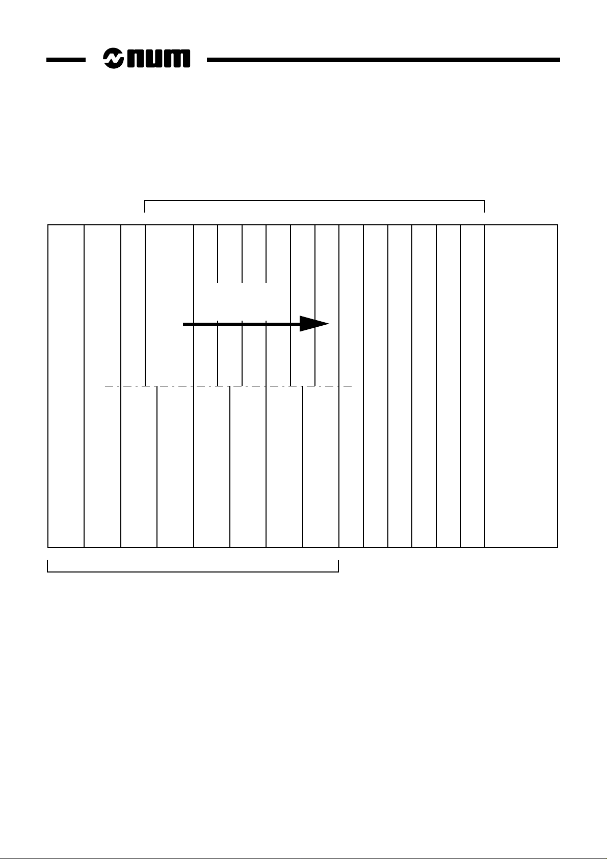
2 System Architecture
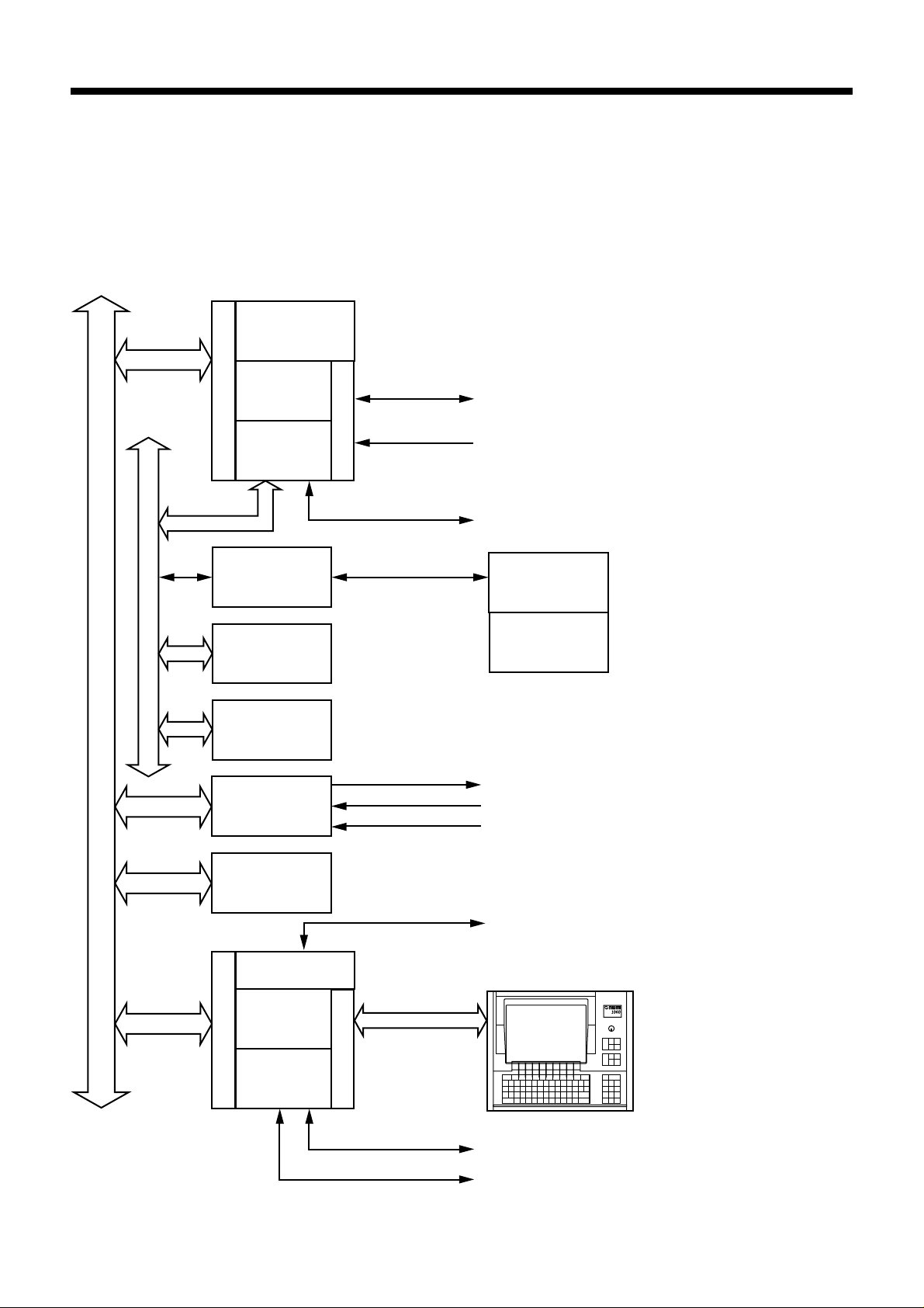
2.1 PCNC 1060 Series II System Architecture
Memory
S
II
CNC function
C
P
U
PLC function
RS 232 serial links
Interrupt
Analogue inputs/outputs
PC Module
Serial bus
System bus
P
C
Serial bus /
optical fibre
adaptation
Inputs
Outputs
Axes
Dedicated
interfaces
PCMCIA
Graphic
function
Machine
panel
Machine
panel
extension (I/O)
Speed reference
Measurement
Origin switch
Type 2 network links
Operator panel
PC
function
RS 232 serial links
Parallel link
en-938928/2 9
Page 10
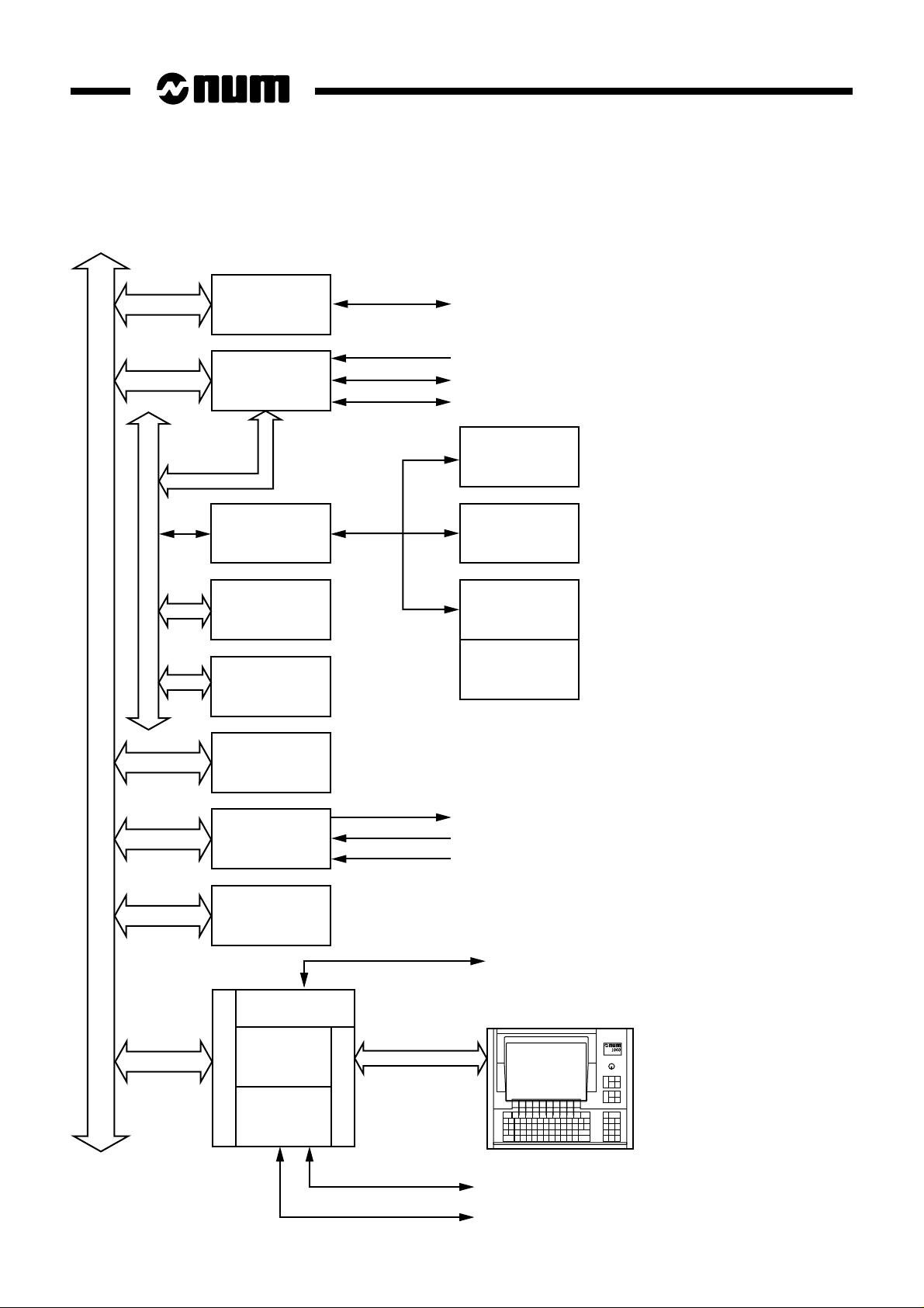
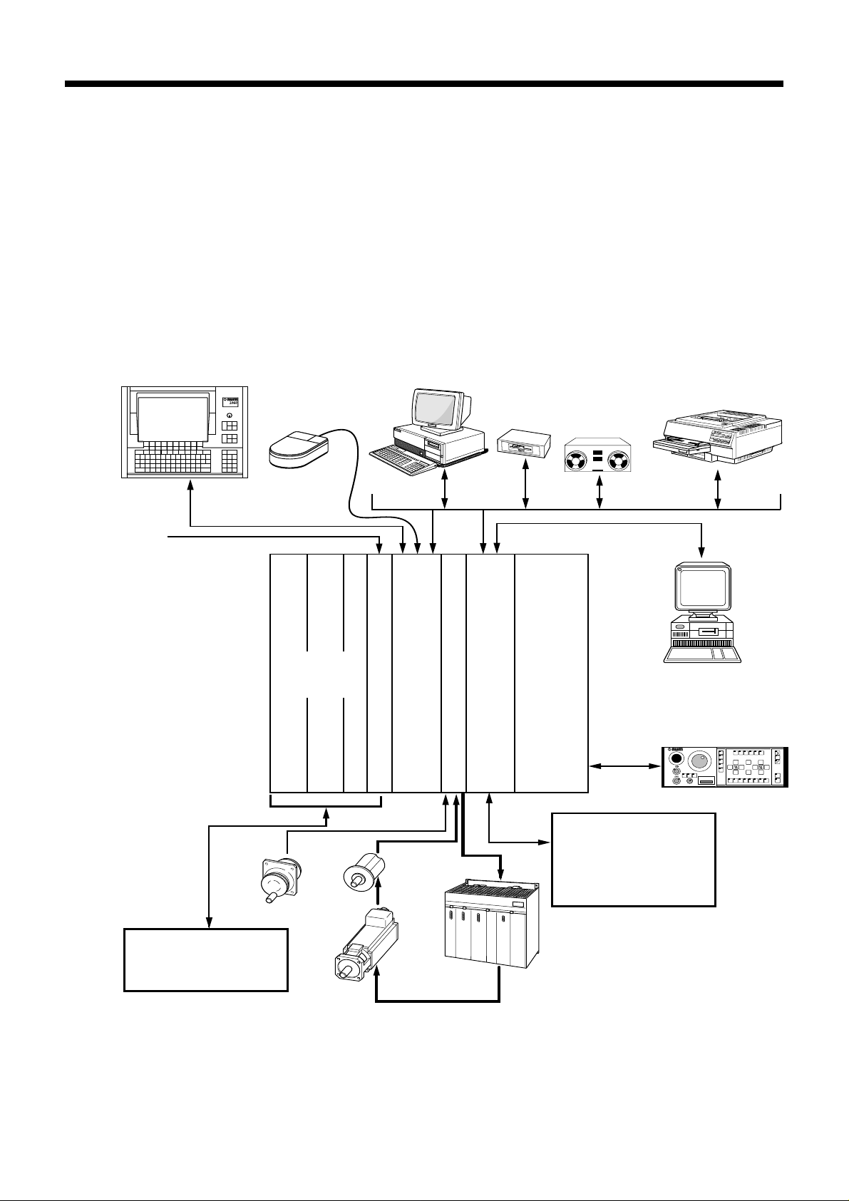
2.2 PCNC 1060 System Architecture
processor
Machine
processor
Serial bus /
optical fibre
adaptation
Inputs
Serial bus
Outputs
CNC
Serial links
Interrupts
Analogue inputs/outputs
Serial links
Remote
inputs
Remote
outputs
Machine
panel
Machine
panel
extension (I/O)
System bus
P
C
Memory
Axes
Dedicated
interfaces
PCMCIA
Graphic
function
PC
function
Speed reference
Measurement
Origin switch
Type 2 network links
Operator panel
RS 232 serial links
10 en-938928/2
Parallel link
Page 11
PC Module
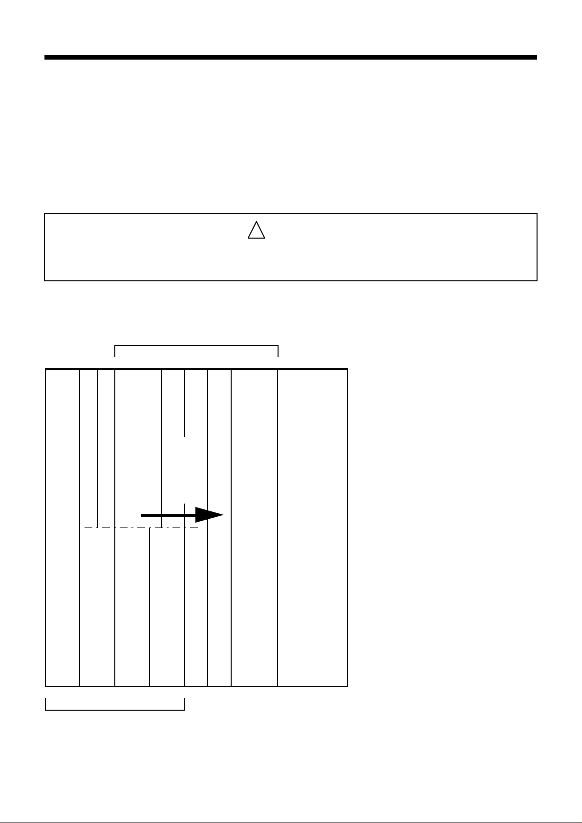
3 Card Layout in the Rack
The CNC cards are installed one after the other starting from the right.
The input/output cards are installed leftward from the first available slot after the CNC cards.
Install blanking covers in the empty slots (10, 20 and 30 mm).
!
The PC module occupies the two slots immediately to the left of the last CNC card installed,
or three slots if the PCMCIA card is connected to it.
3.1 Card Layout in the 1060 Series II Rack
CAUTION
PCMCIA
Slots for CNC cards
452076
To left
of last
PC module
CNC
card
13
Power supply
UC SII Central Processing Unit
8
Slots for input/output cards
765
en-938928/2 11
Page 12
3.2 Card Layout in the 1060 Rack
Slots for CNC cards
11
121314 109876543210
To left of last
CNC card
PCMCIA
12 11 10 8 7 6 5
Slots for input/output cards
PC module
9
Memory card
CNC processor
Machine processor
Power supply
12 en-938928/2
Page 13
4 PCNC Configurations
4.1 PCNC 1060 Series II Configuration
PC Module
Operator panel
Support for
type 1 and 2
PCMCIA cards
Mouse
Input/
output
cards
PC
PCMCIA
PC module
Peripherals
Diskette
drive
Axis card
Tape read
punch unit
Power supply
UC SII Central processing unit
Printer
DNC computer
1 or 2 machine
panels
X
M01
CYCLE
START
CYCLE
STOP
Machine tool
Power cabinet
Automatic controls
Handwheel
Sensor or
rule
Motor
Analogue inputs/outputs
External interrupts
NUM and Customer
applications
Servo-drive
en-938928/2 13
Page 14
4.2 PCNC 1060 Configuration
Operator panel
Support for
type 1 and 2
PCMCIA cards
Input/output cards
Mouse
PCMCIA
PC module
PC
Axis card
Axis card
Memory card
Peripherals
Diskette
drive
CNC processor
Machine processor
Tape read
punch unit
Power supply
Printer
DNC computer
1 to 4 machine
panels
X
M01
CYCLE
START
CYCLE
STOP
Machine tool
Power cabinet
Automatic controls
14 en-938928/2
Sensor or
Handwheel
rule
Motor
Analogue
inputs/outputs
External interrupts
NUM and Customer
applications
Servo-drive
Page 15
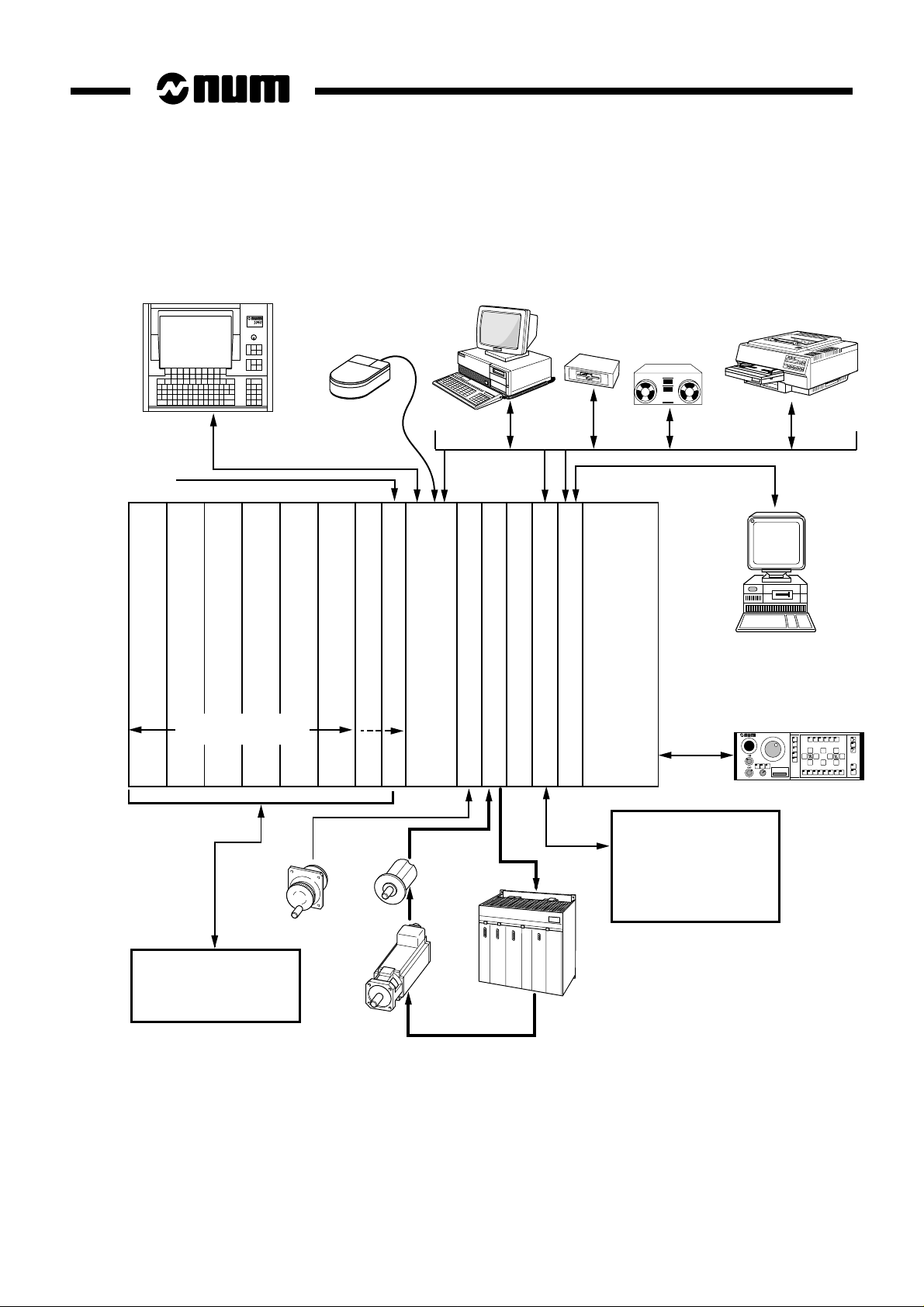
5 PC Module Characteristics
5.1 PC Module Version 1 Characteristics
Power consumption 11 W maximum
Location Last two CNC board slots
External temperature 40 °C maximum
PC Module
(See Chapter 3)
Def.
C
O
M
1
Serial lines
Two RS 232 serial lines (9-pin male connectors)
Maximum input voltage ± 30 V
VOL typical - 9 V
VOH typical + 9 V
Extreme loads 2000 pF, 5kΩ (about 10 m of cable)
Data rate 110 to 9600 bauds with the possibility of
C
O
M
2
Parallel line
increasing to 115 kbauds for local applications
1 parallel line (25-contact female connector)
Mass MB
L
P
T
1
Hard disk
Local memory
8 or 16 MB DRAM
Software programs loaded on hard disk
P
A
N
E
L
L
I
N
K
OS/2 operating system
NUM graphic application
PC module version 1 is a 32-bit processor card with a 486 SX or 486 DX 20 MHz
microprocessor.
It communicates via the system bus with:
- the CNC and machine processors (in the 1060 system)
- the UC SII Central Processing Unit (in the 1060 Series II system)
It can communicate with peripheral equipment via the RS 232 COM1 and COM2
serial lines and a parallel line.
PC Proc.
Console management function
The PC module manages the display and the keyboard via the video link.
The PC data are backed up by a battery with a service life of 36 months.
!
CAUTION
The battery must be replaced after 36 months of use (connected)
en-938928/2 15
Page 16
5.2 PC Module Version 2 Characteristics
Power consumption 11 W maximum
Location Last two CNC board slots
External temperature 40 °C maximum
HD
Def.
Serial lines
(See Chapter 3)
C
O
M
1
Two RS 232 serial lines (9-pin male connectors)
Maximum input voltage ± 30 V
VOL typical - 9 V
VOH typical + 9 V
Extreme loads 2000 pF, 5kΩ (about 10 m of cable)
Data rate 110 to 9600 bauds with the possibility of
C
O
M
2
Parallel line
increasing to 115 kbauds for local applications
1 parallel line (25-contact female connector)
Floppy
L
P
T
1
1 floppy drive connector (37-contact female connector)
LEDs
Def Card fault
HD Lit to indicate read/write accesses to the hard disk
Mass MB
P
A
N
E
L
L
I
N
K
F
L
O
P
P
Y
Hard disk
Local memory
8 or 16 MB DRAM
Software programs loaded on hard disk
OS/2 operating system
NUM graphic application
Proc. PC
16 en-938928/2
PC module version 1 is a 32-bit processor card with a 486 SX or 486 DX 20 MHz
microprocessor.
It communicates via the system bus with:
- the CNC and machine processors (in the 1060 system)
- the UC SII Central Processing Unit (in the 1060 Series II system)
It can communicate with peripheral equipment via the RS 232 COM1 and COM2
serial lines and a parallel line as well as with a diskette drive via the floppy disk
connector.
Page 17

Console management function
The PC module manages the display and the keyboard via the video link.
The PC data are backed up by a battery with a service life of 5 years.
!
CAUTION
The battery must be replaced after 5 years of use (connected)
PC Module
en-938928/2 17
Page 18
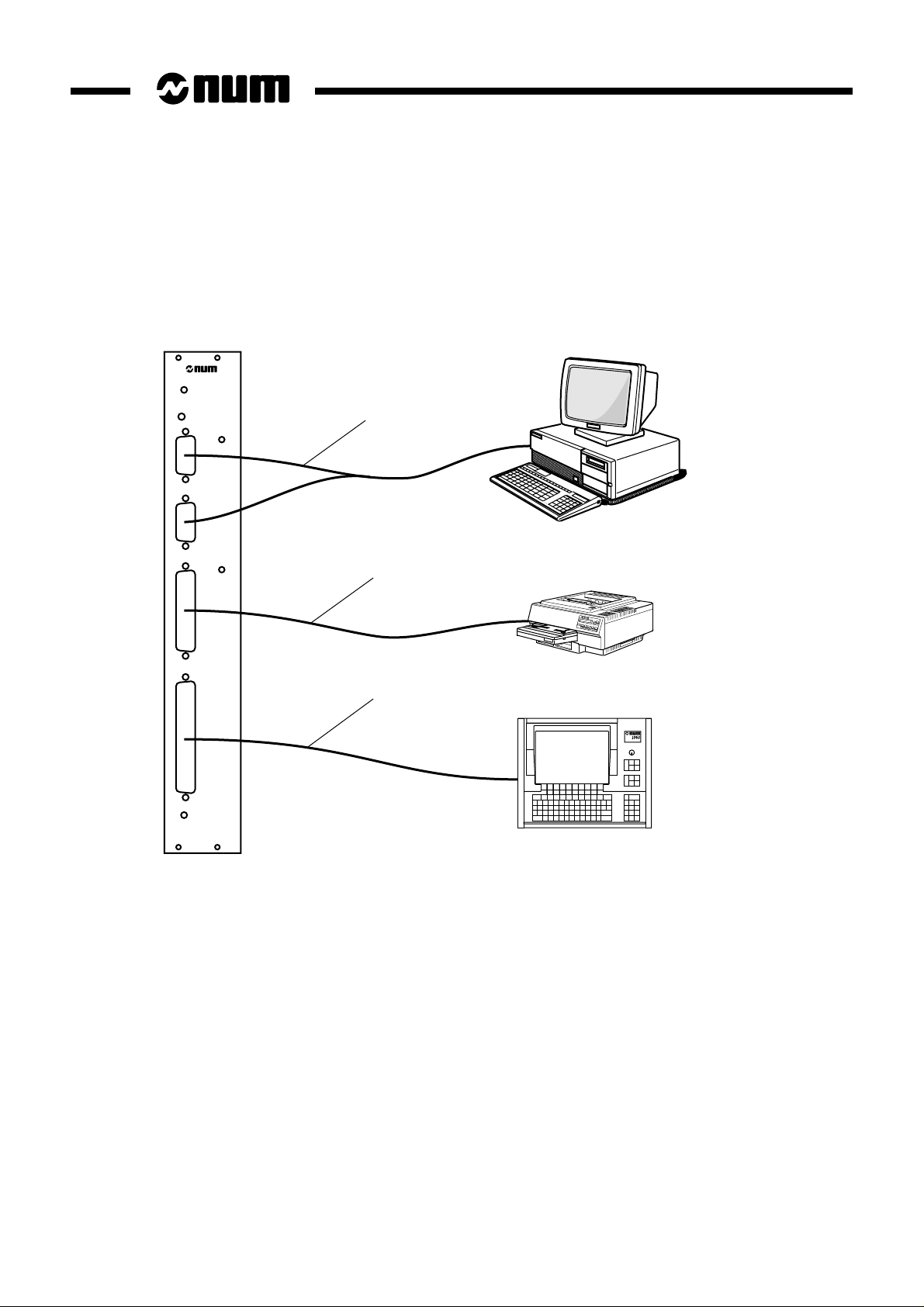
6 PC Module Connection Wiring Diagram
6.1 PC Module Version 1 Connection
M
M
P
A
N
E
N
K
C
O
1
C
O
2
L
P
T
1
L
L
I
Déf.
. PC Proc
1
or
Peripherals
2
Printer
3
Operator panel
1 - Standard RS 232 serial cable
2 - Standard parallel cable
3 - Video cable (see 8.1)
REMARK Card connector J7 can be connected to a standard 3 1/2", 1.44 MB floppy disk
drive (see Secs. 8.2 and 9).
18 en-938928/2
Page 19

6.2 PC Module Version 2 Connection
HD
1
or
Def.
C
O
M
1
C
O
M
2
PC Module
2
Printer
Peripherals
Operator panel
L
P
T
1
3
P
A
N
F
E
L
L
O
P
L
P
I
Y
N
K
Proc. PC
1 - Standard RS 232 serial cable
2 - Standard parallel cable
3 - Video cable (see 8.1)
4 - Diskette drive cable (see 8.2.2)
4
Floppy disk
drive
en-938928/2 19
Page 20

7 PCMCIA Module Characteristics
Location To the left of the PC card, assembled with it
External temperature 40°C maximum
This module can only be connected to the PC version 2 card. The PC and PCMCIA
cards must be inserted together in the rack.
Network Cards Approved by NUM
IBM Ethernet 10DB2 PCMCIA card
National Semiconductor Ethernet NE4100 PCMCIA Infomover
3Com ETHERLINK III 10 base-T card
Installing the Network Card
The card is provided with a polarising (foolproofing) device so that
it can only be inserted in one direction. The polarising slot must
be at the bottom.
Position and insert the card in the slot and press it home. In case
of resistance, do not force. Make sure the card is right side up.
(width 24 mm)
LA CARTE PROC. PC
DO NOT REMOVE THIS CARD
WITHOUT THE PROC. PC CARD
NE RETIRER LA CARTE QU' AVEC
PCMCIA
PC
20 en-938928/2
Polarising slot
Extracting the Network Card
Insert a small screwdriver into the bottom of the PCMCIA module
slot and press gently on the button.
The card is ejected by approximately 1/2 cm from its slot.
Interface socket: The Compaq Concerto software interface is used for the above
network cards (in the system configuration - selective installation of PCMCIA card
socket).
Page 21

8 Cables
8.1 Video Cable
PC Module
Solder side
19
37
20
1
12
1 - 37-contact male sub-D plug
2 - Video cable (see table for cable lengths)
3 - 37-contact female sub-D plug
Solder side
3
19
37
20
1
Video cables:
Length Part Number Length Part Number
5 m 206203222 20 m 206203228
10 m 206203224 30 m 206203230
15 m 206203226 40 m 206203232
en-938928/2 21
Page 22

Red (white wire)
RGround (black wire)
Green (white wire)
GGround (black wire)
Blue (white wire)
BGround (black wire)
HSync (white wire)
HSGround (black wiire)
VSync (white wire)
VSGround (black wire)
VDC
VDC
GND
GND
DATA
GND
CLOCK
Red
7
8
27
28
10
11
30
31
13
14
1
2
20
21 21
Red (0.22)
17
White (0.22)
Blue (0.22)
22
Black (0.22)
35 35
Green
Blue
White
Black
Blue (0.6)
Red (0.6)
White (0.6)
Black (0.6)
Red (0.22)
White (0.22)
Blue (0.22)
Black (0.22)
Red (white wire)
7
RGround (black wire)
8
Green (white wire)
27
GGround (black wire)
28
Blue (white wire)
10
BGround (black wire)
11
HSync (white wire)
30
HSGround (black wire)
31
VSync (white wire)
13
VSGround (black wire)
14
VDC
1
VDC
2
GND
20
GND
DATA
17
GND
22
CLOCK
PROTECTIVE
EARTH
CON-
NECTOR
SHELL
NECTOR
SHELL
CON-
PROTECTIVE
EARTH
Wiring recommendations:
- clamp the cable on a half-cover,
- solder the pins on the other side,
- clamp the other side of the cable on a half-cover,
- solder the pins on the other side.
CAUTION
!
For correct interference suppression of the system, the cable screening must be earthed
(on 360 degrees) in accordance with the instructions of Installation and Commissioning
Manual 938816.
The two clamps must be used to clamp the cable on the cover
22 en-938928/2
Page 23

8.2 Diskette Drive Cable
8.2.1 PC Version 1 Module
J7
3536
PC Module
21
Edge connector to
PC version 1 card
Pinout for connecting a 3 1/2" diskette drive (type TEAFC FD-235HF) to the PC V1 module
Maximum length: 1 metre
GND
RPM/LC
GND
nc
GND
nc
GND
INDEX#
GND
DRV0#
GND
DRV1#
GND
nc
GND
MTRON#
GND
DIR
GND
STEP#
GND
WDATA#
GND
WGATE#
GND
TRK0#
GND
WRPRT#
GND
RDATA#
GND
HDSEL
GND
DSKCHG
GND
VCC
1
2
3
4
5
6
7
8
9
10
11
12
13
14
15
16
17
18
19
20
21
22
23
24
25
26
27
28
29
30
31
32
33
34
35
36
1
GND
2
RPM/LC
3
GND
4
nc
5
GND
6
nc
7
GND
8
INDEX#
9
GND
10
DRV0#
11
GND
12
DRV1#
13
GND
14
nc
15
GND
16
MTRON#
17
GND
18
DIR
19
GND
20
STEP#
21
GND
22
WDATA#
23
GND
24
WGATE#
25
GND
26
TRK0#
27
GND
28
WRPRT#
29
GND
30
RDATA#
31
GND
32
HDSEL
33
GND
34
DSKCHG
24GND
VCC
Protective
earth
en-938928/2 23
Page 24

8.2.2 PC Version 2 Module
Solder side
37
20
19
1
37-contact male
connector
Pinout for connecting a 3 1/2" diskette drive (type TEAFC FD-235HF) to the PC V2 module
Maximum length: 1 metre. For wiring recommendations, see Sec. 8.1.
GND
RPM/LC
GND
nc
GND
nc
GND
INDEX#
GND
DRV0#
GND
DRV1#
GND
nc
GND
MTRON#
GND
DIR
GND
STEP#
GND
WDATA#
GND
WGATE#
GND
TRK0#
GND
WRPRT#
GND
RDATA#
GND
HDSEL
GND
DSKCHG
GND
VCC
GND
Protective
earth
1
20
2
21
3
22
4
23
5
24
6
25
7
26
8
27
9
28
10
29
11
30
12
31
13
32
14
33
15
34
16
35
17
35
18
37
19
COVER
1
GND
2
RPM/LC
3
GND
4
nc
5
GND
6
nc
7
GND
8
INDEX#
9
GND
10
DRV0#
11
GND
12
DRV1#
13
GND
14
nc
15
GND
16
MTRON#
17
GND
18
DIR
19
GND
20
STEP#
21
GND
22
WDATA#
23
GND
24
WGATE#
25
GND
26
TRK0#
27
GND
28
WRPRT#
29
GND
30
RDATA#
31
GND
32
HDSEL
33
GND
34
DSKCHG
24GND
VCC
Protective
earth
24 en-938928/2
Page 25

9 Work on the PC Module
Work is required on the PC module under the following circumstances:
- to replace the battery after 36 months of use for version 1 or 5 years for version 2,
- to extend the memory by adding a DRAM memory module,
- to add the PCMCIA module (PC version 2 module only).
The following diagram shows the locations involved by these operations.
PC Module
14
2
3
1 - Battery connector
2 - Battery
3 - Slot for DRAM memory module
4 - Edge connector for diskette drive (PC version 1 module only)
en-938928/2 25
Page 26

9.1 Replacing the Battery
Refer to the diagram showing the locations on the PC module (see previous page).
!
CAUTION
The battery must be replaced within 15 minutes at most so as not to lose the data backed
up in the PC CMOS RAM. A special capacitor replaces the battery to supply the memories
during replacement.
1 - Disconnect the old battery (1) and remove it (2) from its housing.
2 - Insert the new battery (2) in its housing and connect it (1), ensuring the connector is in the right direction.
9.2 Adding a DRAM Memory Module
The memory module slot is identified (3) in the diagram showing the locations on the PC module.
1 - Push the module into the connector, with the polarizing notch on the left.
2 - Tilt the module towards the vertical until it snaps into place.
Added memory does not have to be declared to the system since it is automatically recognised when power is applied.
Notch
2
1
26 en-938928/2
Page 27

9.3 Adding the PCMCIA Module
The PC card solder side is shown.
Post locations
PC Module
PCMCIA module
connection zone
Screw the three posts in place.
Plug the module into the location provided. The front panel must be in contact with that of the PC module.
Install the three screws.
Plug the PC module in its slot in the rack.
en-938928/2 27
Page 28

10 Using the PC
10.1 Applications Which Can Be Used by the PC
The PC must have OS/2 operating system in version 2.1 or above.
This operating system allows the following types of applications to be executed:
- DOS applications in full screen mode or in a window of the Presentation Manager desktop,
- Windows applications in version 3 and 3.11 for OS2/Warp in a full screen session or a Desktop window of
Presentation Manager
- OS/2 16-bit applications developed under OS/2 versions 1.x,
- OS/2 32-bit applications developed under OS/2 versions 2.x.
All the applications are executed in protected mode. OS/2 is a multitasking pre-emptive shared time system affording
full memory protection between each application.
For more details on the OS/2 operating system, refer to the IBM documentation, especially as regards DOS and
Windows compatibility.
10.2 Using the PC
10.2.1 Config.sys
- The 1060 system can be accessed by a driver which gives access to both the NUM application and the customer
application(s) using the UNI-TE library. The command:
DEVICE=C:\NUM\DRIVER\MEM_GLB.SYS is used to install the driver
- An image of the NUM application (GR_PC.EXE) is contained in the OS/2 STARTUP directory. This directory
is hidden in the STARTUP folder of OS/2. This folder is hidden and is therefore inaccessible to the customer.
CAUTION
!
The following command must mandatorily be included in config.sys:
SETRESTARTOBJECTS=STARTUPFOLDERSONLY, to guarantee that only the NUM
application contained in the STARTUP folder is started at system startup.
- Installation of a mouse. The user can connect a mouse to serial port 1 so that it is recognised by OS/2. The
config.sys file must be modified by deleting the letters REM at the beginning of certain lines:
DEVICE=C:\OS2\MDOS\VMOUSE.SYS
DEVICE=C:\OS2\MOUSE.SYS SERIAL=COM1
- To enable diskette drive a:
Delete the letters REM from the beginning of the following line in config.sys:
REM BASE DEV=IBM1FLPY.ADD
REMARK It is strongly recommended to copy the config.sys file into another directory
before making any changes to it.
The changes made to config.sys are not applied until the system is rebooted
(reset the system).
28 en-938928/2
Page 29

PC Module
10.2.2 NUM Shutdown
Shutdown can be accessed in two ways:
- Access from the NUM application
- Access from the user application.
Access from the NUM Application
Pressing keys Alt and F12 in the NUM application shuts down the PCNC, i.e. all the open applications are closed,
including the NUM application. Shutdown is indicated to the other processors which are then stopped. To be run, this
procedure requires confirmation from the operator in a message box.
Reset after Setting Machine Parameters
In earlier versions, all the applications running on the PCNC were killed by a reset, because it was not possible to tell
which ones accessed the system resources (by requests), made unavailable by a reset.
A new file, REINIT.CFG, is read in the event of a reset:
- If this file is not present or is empty, operation is the same as before, i.e. all the applications are killed.
- If this file contains the name of an application, only this application is killed, but the other applications continue to
run.
The REINIT.CFG file must be located in directory C:\NUM\GRAPHIC.
This file can contain a maximum of 16 application names.
All the applications dialoguing with the system by requests must be included in this file.
If an application is started by the NUM_CLIENT object, it must be included in this file.
The REINIT.CFG file can be edited while the NUM application is running, but a reset is required to take into account
any changes made to it.
Important remark:
- If several instances of the same application are running simultaneously (e.g. C:\OS2\CMD.EXE corresponding
to an OS/2 session window), they are all killed.
- For Windows sessions, if several Windows applications are running in the same session, they are all killed,
since there is no way of identifying a given executable, and the entire session is therefore killed.
The NAMEAPP.EXE utility located in C:\NUM\GRAPHIC is used to identify the applications running when it is started.
It is necessary to use this utility to determine the exact names of the applications (especially for Windows applications).
If several Windows applications are running in the same DOS machine (Virtual DOS Machine), the only way of
identifying the VDM is by the name of the first Windows application started. This is the name which must be stored
in REINIT.CFG (to be checked with NAMEAPP.EXE). The complete VDM is killed.
en-938928/2 29
Page 30

Shutdown
The SHUTDOWN.EXE Num executable was initially run from the NUM application by pressing keys Alt+F12. It killed
all the applications running in the system and started the OS/2 shutdown procedure. This was mainly for the purpose
of requiring the operator to confirm only the shutdown request. In addition, the server and pipeline also invoked
SHUTDOWN.EXE.
Now, pressing the same keys also runs SHUTDOWN.EXE, but this file kills the applications declared in REINIT.CFG,
stops the NUM graphic application, indicates to the other processors that the PCNC is stopping and runs the
SHUT.CMD file. SHUT.CMD contains the default command line START/N C:\NUM\GRAPHIC\KILLAPPS.EXE 6 in
which KILLAPPS.EXE is the executable that performs the final shutdown and stops the system.
It is necessary to specify a parameter when using KILLAPPS.EXE (6 in the above case). This parameter corresponds
to the process ID of the Num application. It can be obtained by running the NAMEAPP.EXE utility in directory
C:\NUM\GRAPHIC. This utility gives the name and ID of each process. In particular, when a network is loaded on
a PCNC under Warp before the NUM application, the parameter specified in SHUT.CMD is no longer 6, but the value
of the GR_PC.EXE process ID obtained from NAMEAPP.EXE.
This method preserves compatibility for the server and pipeline, since the same filename is always invoked. In addition,
it allows the user to edit the SHUT.CMD file, replacing the default line by a line with the format START/N pathname\user
_filename, where user_filename is the name of the user executable used to cleanly shut down the applications (e.g.
networks) and run either KILLAPS.EXE or the OS/2 SHUTDOWN.EXE located in C:\OS2\INSTALL. The main
difference between these two files is that the OS/2 SHUTDOWN.EXE file displays a confirm dialogue box for windowed
applications before proceeding to shutdown.
To summarise:
- If REINIT.CFG is empty, all the applications are killed by a reset (machine parameter modification, etc.)
- If REINIT.CFG is not empty, it should contain the names of all the applications (maximum 16) using 1060 system
resources (UNI-OS2, EDIT-PP, NUM-Bu, etc.).
Access from a User Application
OS/2 Type User Application
The executable running the shutdown procedure is located on the hard disk so that it can be used by an OS/2 type
user application. This executable is called SHUTDOWN.EXE and is located in directory C:\NUM\GRAPHIC.
In this case, no confirmation is requested of the operator.
Application Using the Pipe
For user applications using the pipe, the pipe source code is modified and includes the possibility of requesting
shutdown from a DOS application. The OS/2 pipe code is modified in the same way.
The shutdown is carried out by calling function SHUT_DOWN_PCNC() supplied in library lib_dnc.lib from a DOS or
WINDOWS application. OS/2 is closed without requesting confirmation.
The pipe is a communication facility supplied by NUM between Windows and OS/2 applications. It is used for issuing
DNC1000 requests and receiving replies to these requests. The pipe is created and managed by programme
UNI_OS2.EXE.
WINDOWS applications can send and receive information to and from the pipe using LIB_INIT.DLL.
30 en-938928/2
Page 31

PC Module
In this case, no confirmation is requested of the operator.
!
CAUTION
So as not to corrupt the hard disk, it is recommended to carry out a shutdown procedure
before turning off power.
During the shutdown, all the applications are closed without warning.
If an editor was open, any modifications made are lost. This is also the case for a reset
after modifying machine parameters.
10.2.3 Opening a User Application at Startup
The PCNC can open a user application during system startup. To do so, the user must configure his system by creating
a programme object on the OS/2 desktop whose identifier is known to the NUM application. Use the CREATPRG.CMD
programme supplied on the hard disk in directory C:\NUM.
In an OS/2 session, go into directory C:\NUM and run CREATPRG. The programme creates four programme objects:
“NUM client”, “START Appli”, “NUM Backup” and “EDIT-PP”. The last two are Windows utilities used for saving
machine data and managing files (START Appli is used by the server). Configure the "NUM client" programme object
created on the desktop by modifying its parameters so that it calls the required user application. The user application
can be an OS/2, DOS or WINDOWS executable.
Only the application associated with the "NUM client" object is automatically opened when the NUM application is
started, contrary to the one that can be associated with the "START Appli" object accessible by the PCNC server.
REMARK The user can also run a .CMD command file to start several applications.
After completing the configuration, shut down the system by an OS/2 shutdown accessible from the context-sensitive
menu of the desktop (do not use the NUM shutdown procedure) then reset the system.
The NUM application is started automatically and handles synchronisation with the other microprocessors.
After initialisation, the NUM application detects whether a user application is present on the system. If so, the NUM
application is minimised to an icon and the user application is automatically started. If not, the NUM application
continues to occupy the full screen.
The user can return to the NUM application from his application by displaying the list of active tasks by "Ctrl and Esc"
and selecting the NUM task.
10.2.4 NUM Task/User Task Toggle
The NUM application run when the PCNC is started can be minimised to an icon by simultaneously pressing Alt and
F9, which causes a return to the desktop if no other application is running.
When minimised, the icon is placed in the folder of minimised windows. The operator is on the OS/2 desktop and can
run OS/2 applications.
When the NUM application occupies the full screen, OS/2 controls the actions initiated by simultaneously pressing the
following keys:
- Ctrl and Esc to access the list of tasks
- Alt and Tab to display another open application
- Ctrl, Alt, Del are inoperative.
Two other ways of toggling are available:
- "Iconification" (minimise) (see Sec. 10.4.7)
- "Restitution" (restore) (see Sec. 10.4.8).
en-938928/2 31
Page 32

10.2.5 Creating System Diskettes
Available in OS/2 version 3 and above.
Since the PCNC is supplied with the software already installed and without installation diskettes, it is recommended
to created your own installation diskettes, in particular OS/2.
Use the following procedure:
- On the desktop, double-click the "Diskette Factory" icon
- In the window that opens, select the name of the product for which the installation diskettes are to be created
- Click "Create" and follow the instructions.
10.2.6 Regenerating the Initial Configuration
If a problem occurs, an archive containing the initial system desktop configuration can be restored (but not the NUM
application).
Reboot the system. When a white rectangle appears in the upper left-hand corner of the screen, press ALT+F1.
A utility menu is displayed. Item “X” allows you to regenerate the initial desktop configuration.
10.2.7 Reinstalling the NUM Application
You can reinstall the NUM application and the initial system configuration (except screen drivers - original config.sys
restored) as follows.
Reboot the system. When a white rectangle appears in the upper left-hand corner of the screen, press ALT+F1.
A utility menu is displayed. Item “R” allows you to completely reinstall the NUM application and the initial configuration
delivered. The procedure is started by confirming this selection. The files are restored, the system is booted and an
OS/2 session window is opened. Confirm when requested. At the end of the procedure, a shutdown is executed and
installation is completed.
10.2.8 Backing up the NUM Application
You can create a backup diskette for the NUM application. To do so, return to the desktop (by pressing ALT+F9 when
in the NUM 1060 graphic user interface). Run the Diskette Factory utility and select Num appli to generate the backup
diskette with the NUM application.
To restore the NUM application from the backup diskette, run Install from the diskette (the graphic configuration in
mode SVGA 256c with CL5428 or CL5429 drivers is not restored).
10.2.9 Restoring a Disk: CHKDSK
Exceptionally, the system may be blocked in the case of a general power failure when it was not possible to shut it down
first.
When turned back on, the system refuses to boot and displays the message:
- "Impossible to find PCSHELL.EXE. The system is stopped".
Use the following procedure to correct this problem. It is necessary to have a diskette drive connected to the PC card
and an OS/2 system diskette in HPFS format.
- Insert the diskette in the drive and boot from the diskette
- When the prompt A:> is displayed, enter CHKDSK C:/F.
This starts restoring of the diskette. When it is completed, remove the diskette from the drive and reset.
32 en-938928/2
Page 33

PC Module
10.2.10 Modifying the NUM Application Task Priorities
The task priorities of the GR_PC.EXE application can be modified. Version C3 of the PCNC software allows the
priorities of the four threads of the NUM graphic application to be modified.
10.2.10.1 Description of the Threads
NumExcep
This thread scans the global system memory to check for:
- Reboot requests from other processors,
- Exceptions from the other processors.
It is always active, even when the application is minimised.
Its default priority is Class=2 and Delta=20:
DosSetPriority(2, 2, 20, NumExcep).
NumSelect
This thread reads the graphic command blocks placed in the global memory by the CNC processor, performs INTEL/
MOTOROLA conversion and handles display.
It is suspended when the application is minimised.
Its default priority is Class=2 and Delta=20:
DosSetPriority(2, 2, 20, NumSelect).
NumStat
This thread manages display in the STATUS window.
It is suspended when the application is minimised.
Its default priority is Class=2 and Delta=20:
DosSetPriority(2, 2, 20, NumStat).
NumThread
This thread manages Presentation Manager messages such as the window minimisation command and keyboard
entries transmitted to other processors.
It is always active, even when the application is minimised.
Its default priority is Class=3 and Delta=20:
DosSetPriority(2, 3, 20, NumThread).
10.2.10.2 Modifying the Priorities
The priorities (Class and Delta) of the four threads are set by sending parameters to the GR_PC.EXE executable.
Eight parameters must be passed:
- NumExcep Class
- NumExcep Delta
- NumSelect Class
- NumSelect Delta
en-938928/2 33
Page 34

- NumStat Class
- NumStat Delta
- NumThread Class
- NumThread Delta.
If one of these parameters is missing or a ninth is added, the default priority definitions are applied.
The Class parameters must have a value ≥ 1 and ≤ 4 and the Delta parameters must have a value ≥ -31 and ≤ +31;
otherwise, the default values are applied.
10.2.10.3 Entering the Parameters
To enter the parameters, call the context-sensitive menu of the GR_PC.EXE programme object under C:\NUM\GRAPHIC
and select "Parameters". On the "Programme" page, enter the 8 numerical values separated by spaces in the
"Parameters" field.
Then shut down OS/2 and reset the system.
The modifications are not applied until after the system reset.
10.2.11 Modifying the Colour Palette
Starting with version C3 of the PCNC software, the NUM graphic application colour palette can be edited.
The colour palette is edited using the values entered in file GR_USER.PAL in C:\NUM\GRAPHIC.
This file contains the values corresponding to the basic colours defined by their R, G and B components.
The values are entered hexadecimally in lower case. The modified colours are applied after a system reset.
File of Basic Colours
The basic colours contained in the file are in lower case
{ /* R G B */
{ 0x00 0x00 0x80 }, /*0 : dark blue */
{ 0xff 0xff 0xff }, /*8 : white */
{ 0x00 0xff 0x00 }, /*4 : green */
{ 0x54 0x54 0x54 }, /*12 : dark grey */
{ 0x3c 0xbc 0xff }, /*2 : blue */
{ 0x7c 0xbc 0xff }, /*10 : light blue */
{ 0x00 0xff 0xff }, /*6 : cyan */
{ 0xff 0x3c 0x00 }, /*14 : flashing colour 1: red */
{ 0xff 0x00 0x00 }, /*1 : red */
{ 0x7c 0x3c 0x00 }, /*9 : brown */
{ 0xff 0xff 0x00 }, /*5 : yellow */
{ 0xff 0xbc 0x00 }, /*13 : orange */
{ 0xff 0x80 0xff }, /*3 : pink */
34 en-938928/2
Page 35

PC Module
{ 0xbc 0xbc 0xbc }, /*11 : light grey */
{ 0x00 0x00 0x00 }, /*7 : black */
{ 0xbb 0xbc 0xbc }, /*15 : flashing colour 2: light grey */
{ 0xfe 0xff 0xff }, /*16 : flashing colour 1: white */
{ 0xff 0xfe 0xff }, /*17 : flashing colour 2: white */
};
10.3 Development of Specific Applications
The PC integrated in the CNC allows the use of specific applications:
- customised interface,
- read/write access to the CNC and PLC data (e.g. possibility of modifying the tool dimensions table),
- large volume of mass storage provided by the hard disk for storing the part or PLC programmes and transferring them
to the CNC or PLC memory when required,
- use of a simplified part programming language suited to the application (e.g. language using graphic display) which
is then converted into ISO blocks and can be transmitted on request to the CNC for immediate (drip feed mode) or
deferred use (storage).
The applications running under OS/2 can be developed using IBM C Set/2 including:
- C/C++ tools,
- WorkFrame,
- ToolKit for OS/2.
The applications communicate with the CNC and the PLC through UNI-TE protocol. They use UNI-TE primitives (see
Sec. 10.3.1) to set up all calls and send requests (see Sec. 10.3.2).
The primitive files on the diskette (.obj, .h and .dll files) must be linked with the application to obtain an executable.
10.3.1 UNI-TE Primitives
10.3.1.1 Accessing UNI-TE: Open_Unite() Function
Syntax
USHORT Open_Unite (void)
Description
This primitive lets the application communicate with the 1060 system in requester mode and access requests.
It must always be called at the start of the application before any requests are used.
Answer code
Code Meaning Code Meaning
0 OK other bus access invalid
en-938928/2 35
Page 36

Example
if { (error = Open_Unite ())
printf (("\n %d unite opening error", error);}
10.3.1.2 Opening Logic Ports: Get_Port() Function
Syntax
USHORT Get_Port (UCHAR *port)
&port: address to which the system returns the port number
Description
This primitive is used to allocate a logic port (number 0x70 to 0x7F) through which the requests are sent.
It returns a free logic port number which can be used by the application.
A port has to be opened in order to transmit requests.
Returned code
Code Meaning Code Meaning
0 OK 2 UNI-TE invalid: Open_Unite not executed
1 no port available 3 system error (when OS/2 system
functions were called)
Example
for (i = 0 ; i < 15 ; i++)
{ if ( (error = Get_Port (&port[i])) !=0)
{ printf ("\n error %d opening port[%d]", error, i); }
else
{ printf ("\n OK port[%] =%x", i, port[i]); }
}
10.3.1.3 Freeing Logic Ports: Free_Port Function
Syntax
USHORT Free_Port (UCHAR port)
port: port number to free (0x70 to 0x7F)
Description
This primitive frees the port whose number is given as argument.
A port must not be freed until all the answers awaited have been received.
36 en-938928/2
Page 37

PC Module
Returned code
Code Meaning Code Meaning
0 OK 2 UNI-TE invalid: Open_Unite not executed
1 task does not own the port 3 system error (when searching for the
calling process identifier)
Example
for (i = 0 ; i < 15 ; i++)
{ if ( (error = Free_Port (port[i])) !=0)
{ printf ("\n error %d freeing port[%]", error, i); }
}
10.3.1.4 Sending a Request : Unito() Function
Syntax
UCHAR Unito (UCHAR port, void *adr_buf)
port: source port number (0x70 to 0x7F)
&adr_buf: address of the buffer to be sent
Description
This primitive allows a request to be sent to a server on one of the 16 source ports addressed by Get_Port.
The answer to a request must be requested before sending another request to the same port.
Returned code
Code Meaning Code Meaning
0 send OK 4 port number invalid or not owned
1 buffer too long 5 no server for this request
2 buffer length zero 6 system 1060 access error
3 queue full: Unito not followed by Uniti
Send buffer structure
Buffer start @
(1 word, maximum value 128)
Buffer size
(1 word, not significant)
Request size
Request
(128 bytes maximum)
Written by the
user programme
1 word
en-938928/2 37
Page 38

Example
BufferReq . ReqSize = yy ; /* size of request in bytes */
BufferReq . RequestCode = 0xnn ; /* Request code */
BufferReq . CategoryCode = mm ; /* Category code */
BufferReq . Segment = (UCHAR) Segment ;
BufferReq . Specific = (UCHAR) Specific ;
BufferReq . ObjectAddress = ObjectAddress ;
BufferReq . Quantity = Quantity ;
error = Unito (port[i], &BufferReq);
10.3.1.5 Receiving an Answer: Uniti() Function
Syntax
UCHAR Uniti (UCHAR port, void *adr_buf)
port: source port number (0x70 to 0x7F)
&adr_buf: address of the buffer which will receive the response
Description
This primitive is used to receive an answer to a request sent from the same source port.
As long as code 0x08 is returned (processing of request by server not completed), the function must be repeated
periodically until the answer is obtained.
Returned code
Code Meaning Code Meaning
0 read OK 7 buffer too small to contain the answer
4 port number invalid or not owned 8 no message at this port number
6 system 1060 access error
Receive buffer structure
Buffer start @
(1 word, answer size + 2)
(1 word, maximum value 128)
Buffer size
Answer size
Answer
(128 bytes maximum)
1 word
Written by the
user programme
Written by the
NUM software
38 en-938928/2
Page 39

Example
BufferResp . BufferSize = xx ;
BufferResp . ReqSize = 0 ;
do { error = Uniti (port[i], &BufferResp);
} while (error == NO_MESSAGE);
10.3.1.6 Example of Use of UNI-TE Primitives in an Application
{ /* declaration of variables */
USHORT error = 0;
UCHAR port[16];
#define NO_MESSAGE 0x08;
typedef struct { USHORT BufferSize;
USHORT ReqSize;
UCHAR RequestCode;
UCHAR CategoryCode;
UCHAR Segment;
UCHAR Specific;
USHORT ObjectAdress;
USHORT Quantity;
} Buf_req_client;
typedef struct { USHORT BufferSize;
USHORT ReqSize;
UCHAR ResponseCode;
UCHAR Specific;
UCHAR Data [126];
} Buf_resp_client;
Buf_req_client BufferReq;
Buf_resp_client BufferResp;
...
...
/* unite access */
if { (error = Open_Unite ())
printf ("\n unite %d opening error, error);}
...
/* opening of 16 ports */
for (i = 0 ; i < 15 ; i++)
{ if ( (error = Get_Port (&port[i])) != 0)
{ printf ("\n error %d opening port[%d]", error, i); }
else
{ printf ("\n OK port[%d] = %x", i, port[i]); }
}
...
/* sending a request */
BufferReq . ReqSize = yy ; /* size of request in bytes */
BufferReq . RequestCode = 0xnn ; /* Request code */
BufferReq . CategoryCode = mm ; /* Category code */
BufferReq . Segment = (UCHAR) Segment ;
BufferReq . Specific = (UCHAR) Specific ;
BufferReq . ObjectAddress = ObjectAddress ;
BufferReq . Quantity = Quantity ;
error = Unito (port[i], &BufferReq);
PC Module
en-938928/2 39
Page 40

...
/* receiving a response */
BufferResp . BufferSize = xx ;
BufferResp . ReqSize = 0 ;
do { error = Uniti (port[i], &BufferResp);
} while (error == NO_MESSAGE);
...
/* closing of 16 ports */
for (i = 0 ; i < 15 ; i++)
{ if ( (error = Free_Port (port[i])) != 0)
{ printf ("\n error %d freeing port[%d]", error, i); }
}
...
}
10.3.2 Requests Accessible to the PC
The requests listed below can be accessed by the PC. The requests are detailed in the UNI-TE Protocol Utilization
Manual 938914.
The "Read-Block", "Write-Block" and "Reserve-Memory" requests are described in Sections 10.3.2.3 to 10.3.2.5.
10.3.2.1 List of CNC Requests
Requests Request code Additional request code
Identification 0x0F
Run 0x24
Stop 0x25
Init 0x33
Read-Object 0x36 Segment (list below: code and meaning)
0x80 position reference
0x81 position measurement
0x82 DAT1
0x83 DAT2
0x84 DAT3
0x85 minimum machining limits
0x86 maximum machining limits
0x87 axis inclination
0x88 machine origin
0x89 minimum machine travels
0x8A maximum machine travels
0x8B position reference correction
0x8C axis position reference
0x8D axis position measurement
0x8F servo-controlled axes
0x90 spindle speed measurement
0x91 spindle position measurement
0x92 tool correctors
0x93 H variables
40 en-938928/2
Page 41

Requests Request code Additional request code
0x36 0x95 initialised axes
0x96 E80000 parameters
0x97 E81000 parameters
0x98 E82000 parameters
0x99 program status
0x9D end-of-block dimensions
0xB4 mode
0xB5 current part programme
Write-Object 0x37 Segment (list below: code and meaning)
0x82 DAT1
0x83 DAT2
0x84 DAT3
0x85 minimum machining limits
0x86 maximum machining limits
0x87 axis inclination
0x88 machine origin
0x89 minimum machine travels
0x8A maximum machine travels
0x92 tool correctors
0x93 H variables
0x95 initialized axes
0x96 E80000 parameters
0x97 E81000 parameters
0x98 E82000 parameters
0xB4 mode
0xB5 current part programme
Open-DownLoad-Sequence 0x3A File identification (list below: code and meaning)
0x02 axis calibration
0x05 machine parameters
0x0C part programmes in drip feed mode
0x12 part programmes for storage
Write-DownLoad-Segment 0x3B
Close-DownLoad-Sequence 0x3C
Open-UpLoad-Sequence 0x3D File identification (list below: code and meaning)
0x02 axis calibration
0x05 machine parameters
0x12 part programmes for storage
Read-UpLoad-Segment 0x3E
Close-UpLoad-Sequence 0x3F
Delete-File 0xF5 0x46
Read-Memory-Free 0xF5 0x47
Open-Directory 0xF5 0x48
Directory 0xF5 0x49
Close-Directory 0xF5 0x4A
Read-Block 0xF5 0x50
PC Module
en-938928/2 41
Page 42

Requests Request code Additional request code
Write-Block 0xF5 0x51
Reserve-Memory 0xF5 0x52
10.3.2.2 List of PLC Requests
Requests Request code Additional request code
Status 0x31
Read-Object 0x36 Segment (list below: code and meaning)
0xA0 internal Boolean variables (assembler)
non-saved variables (Ladder)
0xA1 internal numerical variables (assembler)
saved variables (Ladder)
0xA2 double numerical variables (assembler)
common word variables (Ladder)
0xA4 numerical inputs (assembler)
inputs from CNC (Ladder)
0xA5 numerical outputs (assembler)
outputs to CNC (Ladder)
0xA8 Boolean inputs (assembler)
inputs from terminal strip (Ladder)
0xA9 Boolean outputs (assembler)
outputs to terminal strip (Ladder)
0xAC counters (assembler)
0xAE timers (assembler)
Write-Object 0x37 Segment (list below: code and meaning)
0xA0 internal boolean variables (assembler)
non-saved variables (Ladder)
0xA1 internal numerical variables (assembler)
saved variables (Ladder)
0xA2 double numerical variables (assembler)
common word variables (Ladder)
0xA5 numerical outputs (assembler)
outputs to CNC (Ladder)
0xA9 Boolean outputs (assembler)
outputs to terminal strip (Ladder)
0xAC counters (assembler)
0xAE timers (assembler)
0xAF decoded M functions
0xB0 coded M functions
0xB1 T functions
0xB7 handwheels (assembler)
0xB8 counter output (assembler)
0xB9 timer output (assembler)
0xBA background task (assembler)
42 en-938928/2
Page 43

Requests Request code Aditional request code
Open-DownLoad-Sequence 0x3A File identification (list below: code and meaning)
0x0701 %TSi module (Ladder)
0x0702 %TFi module (Ladder)
0x0703 %SPi module (Ladder)
0x0704 %THi module (Ladder)
0x0705 %INI module (Ladder)
0x0710 any module (Ladder)
0x0741 C file
0x0761 text file
Write-DownLoad-Segment 0x3B
Close-DownLoad-Sequence 0x3C
Open-UpLoad-Sequence 0x3D File identification (list below: code and meaning)
0x0701 %TSi module (Ladder)
0x0702 %TFi module (Ladder)
0x0703 %SPi module (Ladder)
0x0704 %THi module (Ladder)
0x0705 %INI module (Ladder)
0x0710 any module (Ladder)
0x0740 C file directory
0x0741 C file
0x0760 text file directory
0x0761 text file
Read-UpLoad-Segment 0x3E
Close-UpLoad-Sequence 0x3F
Delete-File 0xF5 0x46
Stop 0xF5 0x4C
Init 0xF5 0x4D
Run 0xF5 0x4F
PC Module
10.3.2.3 Reading Part Programme Blocks
Description
The Read-Block request is used to read a part programme block.
Transmission
Request code / Additional request code / Programme number / Block number / Block offset
Request code 1 byte: 0xF5
Additional request code 1 byte: 0x50
Programme number 1 long word: indexed programme number (programme number x 10 + axis group
number)
Block number 1 word: block number pointed to
Block offset 1 word: rank of block to be read after the previously selected block (0 to read this
block)
en-938928/2 43
Page 44

Reception
Positive Answer
Answer code / Additional answer code / Block length / Data
Answer code 1 byte: 0xF5
Additional answer code 1 byte: 0x80
Block length 1 word: number of data bytes (maximum 119 including the
LF which ends the block)
Data Character string (ASCII codes) forming the block.
Negative answer
Answer code / Additional answer code
Answer code 1 byte: 0xF5
Additional answer code 1 byte: 0x80
10.3.2.4 Writing Part Programme Blocks
Description
The Write-Block request is used to add, modify or delete a part programme block.
REMARK Unlike the other requests, the Write-Block request can contain up to 132 bytes
Transmission
Request code / Additional request code / Programme number / Block number / Block Offset /
Block length / Data
Request code 1 byte: 0xF5
Additional request code 1 byte: 0x51
Programme number 1 long word: indexed programme number (program number x 10 +
axis group number)
Block number 1 word: block number pointed to
Block offset 1 word: rank of unnumbered block pointed to after the previously
selected block (0 to stay on this block)
Block length 1 word: number of data bytes (120 maximum)
Data Character string (ASCII codes) forming the block to be sent
(the block must end with LF : ASCII code 0x0A)
- "-LF" to delete the block selected
- "+[block]LF" to insert the block after the block selected
- "#[block]LF" to substitute the block for the block selected
REMARK The block writing method is similar to the block modification method (see
Operator Manual).
44 en-938928/2
Page 45

PC Module
Reception
Answer code / Additional answer code
Answer code 1 byte: 0xF5
Additional answer code 1 byte: 0x81
The answer code and the additional answer code are not significant: it is the code returned by the Uniti() function that
gives the request execution report.
10.3.2.5 Reserving Memory Space
Description
The Reserve-Memory request is used to reserve memory space for making modifications to an existing programme
without being in reset status.
Transmission
Request code / Additional request code / Programme number / Memory size
Request code 1 byte: 0xF5
Additional request code 1 byte: 0x52
Programme number 1 long word: indexed programme number (programme number x 10 + axis group
number)
Memory size 1 long word: size in bytes to be reserved for the program (0 to keep the program
at its present size)
Reception
Answer code / Additional answer code
Answer code 1 byte: 0xF5
Additional answer code 1 byte: 0x82
The answer code and additional answer code are not significant: it is the code returned by the Uniti() function that gives
the request execution report.
en-938928/2 45
Page 46

10.4 Functional Description of the PCNC Server
The CNC can send requests to the PC module. In this case, the PC module is the server.
Whenever a request is sent to the PC, it is received by the driver, which wakes up the server task. This task recovers
the data, decodes the request, performs the necessary processing and acknowledges the request by updating the
control data.
10.4.1 OPEN-DOWNLOAD-SEQUENCE Request
Description
This request starts loading a file on the PCNC HD (hard disk).
Request Format
Request code/Category/File identifier/Extension code/Filename
Request code: 1 byte: 0x3A
Category: 1 byte
File identifier: 2 long words (long word 1 at the low address, long word 2 at the high address)
long word 1: file identifier
long word 2: not significant
REMARK The high byte of this long word gives the file type; type 9 corresponds to the
PCNC; the next three bytes are not significant.
Extension code: 1 byte: 0x01
Optional field (see next field)
Filename: table of bytes (ASCII character string beginning with a length byte)
Optional field present only if the Extension code is present and equal to 0x01
Syntax: "C:\filename" or "C:\path\filename"
REMARK The Filename field gives the filename and possibly also the pathname of the
files to be downloaded. It must always be specified in the case of the PCNC.
Answer Format
Answer code/Status
Positive Answer
Answer code: 1 byte: 0x6A
Status: 1 byte: 0x00
46 en-938928/2
Page 47

Negative Answer
Answer code: 1 byte: 0x6A
Status: 1 byte: 0x01: file already exists
0x02: other download in progress
0x03: memory full
0x08: error in filename/header
0x1C: system error
10.4.2 WRITE-DOWNLOAD-SEGMENT Request
Description
This request is used to write data in a file that is already open.
PC Module
Request Format
Request code/Category/Segment number/Segment length/Data
Request code: 1 byte: 0x3B
Category: 1 byte
Segment number: word
Segment length: word
Data: table of bytes
Answer Format
Answer code/Status/Segment number
Positive Answer
Answer code: 1 byte: 0x6B
Status: 1 byte: 0x00
Segment number: word
Negative Answer
Answer code: 1 byte: 0x6B
Status: 1 byte: 0x03: Memory full
0x04: no file open
0x08: download already in progress
0x09: data length inconsistent with request received
0x0B: a block has more than 120 characters
0x0D: incoherent data
en-938928/2 47
Page 48

0x19: sequence error
0x1C: system error
Segment number: word
10.4.3 CLOSE-DOWNLOAD-SEQUENCE Request
Definition
This request is used to close download of a file already open.
Request Format
Request code/Category
Request code: 1 byte: 0x3C
Category: 1 byte
Answer Format
Answer code/Status
Positive Answer
Answer code: 1 byte: 0x6C
Status: 1 byte: 0x00
Negative Answer
Answer code: 1 byte: 0x6C
Status: 1 byte: 0x04: file already closed
0x08: other download in progress
0x0B: the last block loaded does not end with "LF": file deleted
0x1C: system error
10.4.4 OPEN-UPLOAD-SEQUENCE Request
Definition
This request is used to start upload of a file from the PCNC.
Request Format
Request code/Category/File identifier/Extension code/Filename
Request code: 1 byte: 0x3D
Category: 1 byte
File identifier: 2 long words (long word 1 at the low address, long word 2 at the high address)
long word 1: file identifier
long word 2: not significant
48 en-938928/2
Page 49

PC Module
REMARK The high byte of long word 1 specifies the file type. Type 9 corresponds to the
PCNC.
Byte 2 gives the subtype:
- value 0: file directory on the disk according to the pathname given in
Filename, syntax: "C:\*.*" or "C:\pathname\*.extension"
The data Read format is 8.3 (operates only on 8.3 format files in HPFS
mode) : a filename is encoded on 3 long words
- value 1: file stored on the disk.
The next two bytes are not significant.
Extension code: 1 byte: 0x01
Optional field (see next field)
Filename: table of bytes (ASCII character string beginning with a length byte)
Optional field present only if the Extension code is present and equal to 0x01
Answer Format
Answer code/Status
Positive Answer
Answer code: 1 byte: 0x6D
Status: 1 byte: 0x00
Negative Answer
Answer code: 1 byte: 0x6D
Status: 1 byte: 0x02: other download in progress
0x05: no such file
0x08: error in filename/header
0x1C: system error
10.4.5 READ-UPLOAD-SEGMENT
Definition
This request is used to upload data from a file that is already open.
Request Format
Request code/Category/Segment number
Request code: 1 byte: 0x3E
Category: 1 byte
Segment number: word
Answer Format
Answer code/Status/Segment number/Segment length/Data
en-938928/2 49
Page 50

Positive Answer
Answer code: 1 byte: 0x6E
Status: 1 byte: 0x00: OK, more data to be transmitted
0x0F: OK, end of file (automatic close)
Segment number: word
Segment length: word
Data: table of bytes
Negative Answer
Answer code: 1 byte: 0x6E
Status: 1 byte: 0x04: no download in progress
0x08: other download in progress
0x09: buffer too small for the answer
0x19: sequence error
0x1C: system error
Segment number: word
Segment length: word
Data: table of bytes
10.4.6 CLOSE-UPLOAD-SEQUENCE
Definition
This request is used to close the upload of a file already open.
Request Format
Request code/Category
Request code: 1 byte: 0x3F
Category: 1 byte
Answer Format
Answer code/Status
Positive Answer
Answer code: 1 byte: 0x6F
Status: 1 byte: 0x00
50 en-938928/2
Page 51

PC Module
Negative Answer
Answer code: 1 byte: 0x6F
Status: 1 byte: 0x04: file already closed
0x08: other download in progress
0x1C: system error
10.4.7 "ICONIFICATION" (Minimise) Request
Definition
This request minimises the NUM application icon on the PCNC. After reception of this request, the icon associated
with the NUM application is placed in the "Minimised windows" folder.
Request Format
Request code/Category/Additional request code/Reserved
Request code: 1 byte: 0xF5
Category: 1 byte
Additional request code: 1 byte: 0x62
Reserved: 1 byte: 0x00
Answer Format
Answer code/Additional answer or request code/Status
Positive Answer
Answer code: 1 byte: 0xF5
Additional answer code: 1 byte: 0x92
Status: 1 byte: 0x00
Negative Answer
Answer code: 1 byte: 0xF5
Additional request code: 1 byte: 0x92
Status: 1 byte: 0x04: application already minimised
0x1C: system error
10.4.8 "RESTITUTION" (Restore) Request
Definition
This request restores the NUM application on the PCNC screen.
Request Format
Request code/Category/Additional request code/Reserved
en-938928/2 51
Page 52

Request code: 1 byte: 0xF5
Category: 1 byte
Additional request code: 1 byte: 0x63
Reserved: 1 byte: 0x00
Answer Format
Answer code/Additional answer or request code/Status
Positive Answer
Answer code: 1 byte: 0xF5
Additional answer code: 1 byte: 0x93
Status: 1 byte: 0x00
Negative Answer
Answer code: 1 byte: 0xF5
Additional request code: 1 byte: 0x93
Status: 1 byte: 0x04: application already restored to full screen
0x1C: system error
10.4.9 "VERROUILLAGE/DEVERROUILLAGE" (Lock/Unlock) Request
Definition
This request is used to inhibit access to the OS/2 desktop (the PCNC is locked on the application in the foreground).
Calling this request toggles the system status from locked to unlocked or vice versa.
Format Request
Request code/Category/Additional request code/Reserved
Request code: 1 byte: 0xF5
Category: 1 byte
Additional request code: 1 byte: 0x64
Reserved: 1 byte: 0x00
Answer Format
Answer code/Additional answer or request code/Status
Positive Answer
Answer code: 1 byte: 0xF5
Additional answer code: 1 byte: 0x94
Status: 1 byte: 0x00: OK, locked
0x01: OK, unlocked
52 en-938928/2
Page 53

PC Module
Negative Answer
Answer code: 1 byte: 0xF5
Additional request code: 1 byte: 0x94
Status: 1 byte: 0x1C: system error
A second request of this type returns the system to its initial state.
REMARK Only operates for a full screen OS/2 application, but not for a DOS or Win/OS2
application.
10.4.10 SHUTDOWN Request
Request Format
Request code/Category/Additional request code/Reserved
Request code: 1 byte: 0xF5
Category: 1 byte
Additional request code: 1 byte: 0x66
Reserved: 1 byte: 0x00
Answer Format
Answer code/Additional answer or request code/Status
Positive Answer
Answer code: 1 byte: 0xF5
Additional answer code: 1 byte: 0x96
Status: 1 byte: 0x00
Negative Answer
Answer code: 1 byte: 0xF5
Additional request code: 1 byte: 0x96
Status: 1 byte: 0x1C
Reception of this request runs an executable that shuts down the PCNC and reports shutdown to the other processors.
REMARK Any changes made at OS/2 level (icon moved, session parameters changed)
are lost with this type of shutdown. To save them, the system must be shut
down using the conventional OS/2 shutdown procedure (accessible on the OS/
2 desktop context-sensitive menu).
en-938928/2 53
Page 54

10.4.11 START-APPLI Request
Definition
This request is used to run an application (executable) present on the hard disk, and associated with the START-APPLI
file. This object must first be created by running the creatprg.cmd file from C:\num.
Request Format
Request code/Category/Additional request code/Reserved
Request code: 1 byte: 0xF5
Category: 1 byte
Additional request code: 1 byte: 0x65
Reserved: 1 byte: 0x00
Answer Format
Answer code/Additional answer or request code/Status
Positive Answer
Answer code: 1 byte: 0xF5
Additional answer code: 1 byte: 0x95
Status: 1 byte: 0x00
Negative Answer
Answer code: 1 byte: 0xF5
Additional request code: 1 byte: 0x95
Status: 1 byte: 0x05: no such application
0x1C: system error
10.4.12 DELETE-FILE Request
Definition
This request deletes a file from the PCNC hard disk.
Request Format
Request code/Category/Additional request code/File identifier/Extension code/Filename
Request code: 1 byte: 0xF5
Category: 1 byte
Additional request code: 1 byte: 0x46
File identifier: long word
Extension code: 1 byte: 0x01: Optional field (see next field)
54 en-938928/2
Page 55

Filename: table of bytes (ASCII character string beginning with a length byte)
Optional field present only if Extension code is present and equal to 0x01
Syntax: "C:\filename" or "C:\path\filename"
Answer Format
Answer code/Additional answer or request code/Status
Positive Answer
Answer code: 1 byte: 0xF5
Additional answer code: 1 byte: 0x76
Status: 1 byte: 0x00
Negative Answer
Answer code: 1 byte: 0xF5
PC Module
Additional request code: 1 byte: 0x76
Status: 1 byte: 0x05: no such file
0x06: file protected
0x1C: system error
Example
Request: 245/0/70/9/01/H'08-43-3A-5C-41-4C-50-48-41
Answer: 245/118/06
245 = DELETE-FILE Request
0 = Category
70 = Additional request code
9 = File identifier
01 = Optional field
H'08 = Filename length (80 bytes)
H'43-3A-5C .... = C:\alpha (filename)
118 = Additional answer code
06 = Protected file
10.4.13 READ-MEMORY-FREE
Definition
This request returns the number of bytes available in the following memory areas:
- User programmes: areas 0, 1, 2 and 3,
- PLC programme (Ladder and C),
- MMI memory area,
- PC module hard disk
en-938928/2 55
Page 56

Request Format
Request code/Category/Additional request code/Area
Request code: 1 byte: 0xF5
Category: 1 byte
Additional request code: 1 byte: 0x47
Area: 1 byte: 0 to 3: User programmes
7: PLC programme (Ladder or C)
8: MMI memory area
9: PC Module hard disk
Answer Format
Answer code/Additional answer or request code/Status/Value
Positive Answer
Answer code: 1 byte: 0xF5
Additional answer code: 1 byte: 0x77
Status: 1 byte: 0x00
Value: long word
Negative Answer
Answer code: 1 byte: 0xF5
Additional request code: 1 byte: 0x77
Status: 1 byte: 0x1C: system error
10.4.14 UNSOLICITED-DATA Request
Definition
This request allows a server to send information without having first received a request. No answer is required of the
receiver.
The PLC sends this request by function Uneto.
The CNC server sends this request when it encounters instruction $9 in the programme being executed.
In the case of the PLC, no report is possible so there is no guarantee that the data were correctly received.
Description of Instruction $i in the Part Programme
In this instruction, the character $ is followed by number i then a character string. This string is the message to be sent.
For the PCNC, i = 9 for unsolicited data sent to the PCNC user programme.
This message is of the nonblocking type. Execution of the part programme continues without waiting for an answer.
56 en-938928/2
Page 57

PC Module
Request Format
Request code/Category/Object-address/Data-length/Data-specific
Request code: 1 byte: 0xFc
Category: 1 byte: 0x06
Object-address: 1 byte: (code giving the origin of the unsolicited data; optional except on a
network)
Index of the axis group
Data-length: 1 byte: number of bytes contained in the Data-specific field
Data-specific: table of bytes
Message contained in the part programme after $9
The message sent by the CNC is accessible via a port. Eight ports are available. Each port is assigned to an axis group:
- $90 for group 1,
- $91 for group 2,
- • • • • •
- $97 for group 8
$98 : unsolicited PLC data.
Answer Format
There is no answer to this request. It can, however, in the case of the CNC, be associated with another UNI-TE request
sent by the recipient of the unsolicited data. This request then acknowledges the unsolicited data. The method
described below can be used to cause a wait for this acknowledgement.
REMARK There is no possible acknowledgement in the case of unsolicited data sent by
the PLC.
Message Acknowledgement
After sending a blocking type message ($91), the CNC goes on wait for a report from the application. The report must
be sent by the application processing the unsolicited data to stop cyclic retransmission of the data (approximately once
every 10 seconds). This acknowledgement is generated by sending the UNITEWRITE-OBJECT request with segment
226 (and an object-address corresponding to the correct axis group). Writing of this segment can achieve two different
actions:
- Writing of the value 1 means that the message was received by the remote application. The CNC stops cyclic
retransmission of the message but part programme execution remains suspended,
- Writing of the value 2 cause execution of the part programme to be resumed.
Acquisition of a Return Value
After transmission of a blocking message, it is possible to recover a value sent by the remote application in the part
programme by programming the instruction Ln = $9 after instruction $9 described above.
The value to be recovered is written by sending the UNITE WRITE-OBJECT request with segment = 224 (and an
object-address corresponding to the correct axis group). The long word forming the data of this request is assigned
to parameter Ln.
en-938928/2 57
Page 58

The use of the "Unsolicited data" request requires initialising the resources and allocating the port(s) corresponding
to the axis group(s) sending them. This is done by calling:
- USHORT Open_Buf_Uns_Data(void) which allows the application to obtain access to the unsolicited data. It must
be called at the beginning of the user application.
Return code: 0: OK
other: invalid system access.
- USHORT Get_Port_S(UCHAR*port,UCHART*typ_port) allows the allocation of ports:
typ_port: 0: requester mode; a port (from $70 to $7F) is returned,
1: Server mode; access to unsolicited data: it is then necessary to send a port number (from $90
to $98) in *port to specify where the unsolicited data are to be received.
High Speed Drip Feed Mode
The high speed drip feed mode is included in a Windows utility accessible from the Diskette Service CNC menu.
The NUM application is minimised to an icon and the EDIT-PP application appears.
The high speed drip feed mode is activated by key F2 after selecting the programme to be run. When drip feed mode
is active, press key F9 to return to the CNC application. EDIT-PP continues to run. To stop and exit EDIT-PP, press
ESC. This does not stop the current file transfer, since the task performing high speed drip feed is independent of EDITPP once activated.
Utilities
Two Windows utilities are available:
- EDIT-PP (see above) for managing files
- NUM Backup for backing up machine data and programmes accessible by item 6, Backup, of the CNC Utilities
menu.
These utilities each use one of the 16 UNITE ports to dialogue with the system and one dedicated pipeline (UNI-OS2).
On-line help is provided for using these utilities.
58 en-938928/2
 Loading...