

Page 1

NUM 1060
PROFIL
USER'S
MANUAL
en-938937/0
02-95 en-938937/0
Page 2

Despite the care taken in the preparation of this document, NUM cannot guarantee the accuracy of the information it contains and cannot be held
responsible for any errors therein, nor for any damage which might result from the use or application of the document.
The physical, technical and functional characteristics of the hardware and software products and the services described in this document are subject
to modification and cannot under any circumstances be regarded as contractual.
The programming examples described in this manual are intended for guidance only. They must be specially adapted before they can be used in
programs with an industrial application, according to the automated system used and the safety levels required.
© Copyright NUM 1995.
All rights reserved. No part of this manual may be copied or reproduced in any form or by any means whatsoever, including photographic or magnetic
processes. The transcription on an electronic machine of all or part of the contents is forbidden.
© Copyright NUM 1995 software CNC NUM 1060.
This software is the property of NUM. Each memorized copy of this software sold confers upon the purchaser a non-exclusive licence strictly limited
to the use of the said copy. No copy or other form of duplication of this product is authorized.
2 en-938937/0
Page 3

Table of Contents
Table of Contents
1 General Description of the PROFIL Function 1 - 1
1.1 General 1 - 3
1.2 Capabilities of the PROFIL Function 1 - 3
1.3 PROFIL Operating Procedures 1 - 4
1.4 Coordinate System 1 - 11
1.5 Entering and Exiting from the PROFIL
Function 1 - 12
1.6 Contour Numbering 1 - 16
1.7 Calling a Contour Created by PROFIL 1 - 17
1.8 Description of the Programme Generated
by PROFIL 1 - 20
2 Creating and Editing Contours 2 - 1
2.1 Contour Types 2 - 3
2.2 Geometric Elements and Construction
Aid Tools 2 - 7
2.3 Geometric Transformation Tools 2 - 30
2.4 Miscellaneous Tools 2 - 35
3 Examples of Contour Creation 3 - 1
3.1 Example of Milled Workpiece 3 - 3
3.2 Creating a Milled Workpiece Contour 3 - 4
3.3 Example of Turned Workpiece 3 - 10
3.4 Creating a Turned Workpiece Contour 3 - 11
en-938937/0 3
Page 4

4 en-938937/0
Page 5
DOCUMENT REVISIONS
Table of Contents
Record of Revisions
Date
02-95 0 Document creation
Revision
Reason for revision
en-938937/0 5
Page 6

6 en-938937/0
Page 7
Structure of the NUM 1060 Documentation
NUM 1060
DYNAMIC
OPERATORS
938871
User Documents
These documents are designed for the operator of the numerical control.
Foreword
Foreword
NUM 1060M/W
OPERATOR’S
MANUAL
938821
OEM Documents
NUM 1060
INSTALLATION
AND
COMMISSIONING
MANUAL
938816
NUM 1060T
OPERATOR’S
MANUAL
938822
NUM 1060M
PROGRAMMING
MANUAL
V
OLUME
1
V
OLUME
2
938819
NUM 1060T
PROGRAMMING
MANUAL
V
OLUME
1
V
OLUME
2
938820
NUM 1060G
CYLINDRICAL
GRINDING
PROGRAMMING
MANUAL
938930
These documents are designed for the OEM integrating the numerical control on a
machine.
NUM 1060
PARAMETER
MANUAL
938818
NUM 1060
AUTOMATIC
CONTROL
FUNCTION
PROGRAMMING
MANUAL
LADDER
LANGUAGE
938846
NUM 1060
PROCAM
DESCRIPTION
MANUAL
938904
COMMISSIONING
NUM 1060G
CYLINDRICAL
GRINDING
MANUAL
938929
NUM 1060H/HG
GEAR
CUTTING AND
GRINDING
MANUAL
938932
en-938937/0 7
Page 8
Special Programming Documents
NUM 1060
RIGID
TAPPING
MANUAL
938881
These documents concern special numerical control programming applications.
NUM 1060
SUPPLEMENTARY
PROGRAMMING
MANUAL
938872
NUM 1060
SYNCHRONISATION
OF TWO SPINDLES
938854
NUM 1060M
PROCAM MILL
INTERACTIVE
PROGRAMMING
MANUAL
938873
NUM 1060
PROFIL
FUNCTION
USER’S
MANUAL
938937
NUM 1060T
PROCAM TURN
INTERACTIVE
PROGRAMMING
MANUAL
938874
NUM 1060
DUPLICATED
AND
SYNCHRONISED
AXES
938875
8 en-938937/0
Page 9
PROFIL User’s Manual
CHAPTER 1
GENERAL
DESCRIPTION OF
THE PROFIL
FUNCTION
Foreword
Description of the capabilities and operating procedures of the PROFIL function.
CHAPTER 2
CREATING AND
EDITING
CONTOURS
CHAPTER 3
EXAMPLES OF
CONTOUR
CREATION
Overview of the contours that can be created by PROFIL and description of the
elements and tools used to create contours.
Examples illustrating the creation of contours (one example for milling and one for
turning).
en-938937/0 9
Page 10

Agencies
Questionnaire
The list of NUM agencies is given at the end of the manual.
To help us improve the quality of our documentation, we kindly request you to return
the questionnaire at the end of this manual.
10 en-938937/0
Page 11

General Description of the PROFIL Function
1 General Description of the PROFIL Function
1.1 General 1 - 3
1.2 Capabilities of the PROFIL Function 1 - 3
1.3 PROFIL Operating Procedures 1 - 4
1.3.1 Configuration of a PROFIL Screen Page 1 - 4
1.3.2 Description of Windows 1 - 5
1.3.2.1 CNC Status Window 1 - 5
1.3.2.2 Graphic Window 1 - 5
1.3.2.3 Data Window 1 - 5
1.3.2.4 Dialogue Window 1 - 5
1.3.2.5 Main Contents of the Dialogue Window 1 - 5
1.3.3 Information on the CNC Keyboard 1 - 8
1.3.3.1 Function Keys 1 - 8
1.3.3.2 Cursor Control Keys 1 - 8
1.3.3.3 Other Keys 1 - 9
1.3.3.1 Notes on Entry of Values 1 - 9
1.3.4 Data or Value Entry Fields 1 - 10
1.4 Coordinate System 1 - 11
1.5 Entering and Exiting from the PROFIL Function 1 - 12
1.5.1 Entering PROFIL 1 - 12
1.5.2 Exiting from PROFIL 1 - 15
1.5.2.1 Example of Exit 1 - 15
1.6 Contour Numbering 1 - 16
1.7 Calling a Contour Created by PROFIL 1 - 17
1.7.1 Contour Call by Function G77 1 - 17
1.7.2 Calling a Contour from a Machining Cycle 1 - 19
1.8 Description of the Programme Generated by PROFIL 1 - 20
1.8.1 Description of an Entity 1 - 20
1.8.2 Structure of a Programme Generated 1 - 21
1
en-938937/0 1 - 1
Page 12

1 - 2 en-938937/0
Page 13

General Description of the PROFIL Function
1.1 General
PROFIL is a graphic module installed in the numerical control (CNC).
PROFIL can be used to create contours of milled or turned workpieces, etc., using
ISO programming or PROCAM interactive programming.
1.2 Capabilities of the PROFIL Function
PROFIL allows the user to create all or part of workpiece contours made up of a
sequence of geometric elements (irregular or freehand contours) or predefined
shapes (rectangles, circles or polygons) then machine these contours by calling
subroutines.
PROFIL also offers the possibility of:
- Immediately viewing the contour elements being created
- Modifying a contour being created or editing a contour already created
- Transforming, duplicating or deleting a contour.
1
It should be noted that:
- Contour creation can be carried out in background mode (during execution of a
part programme)
- The contours are generated by PROFIL in ISO language
- PROFIL can be used in place of the Profil Geometry Programming (PGP) function.
en-938937/0 1 - 3
Page 14
1.3 PROFIL Operating Procedures
When creating or editing a contour, the user must make choices in a page displayed
on the screen.
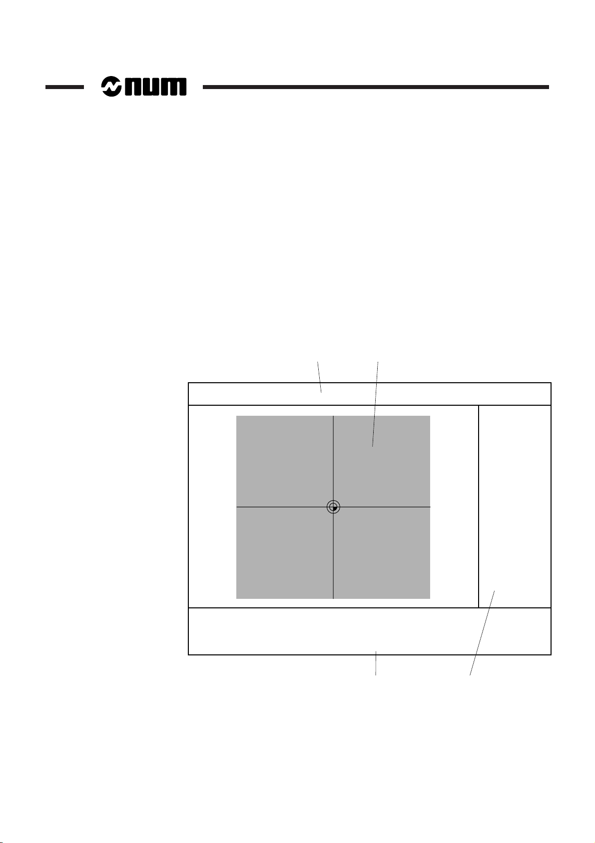
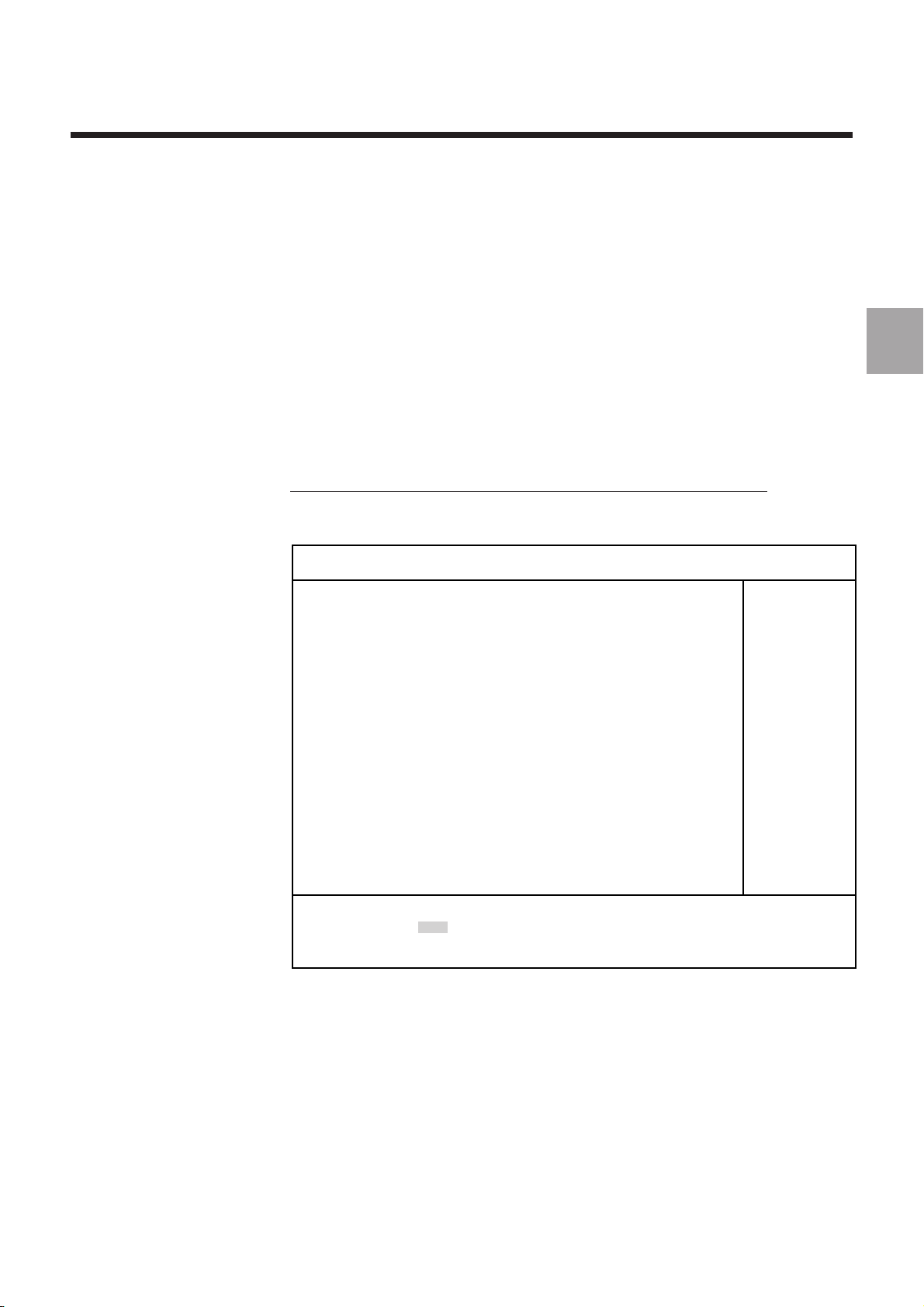
1.3.1 Configuration of a PROFIL Screen Page
The PROFIL function uses a special screen page configuration. This page includes
four windows, three of which are dedicated to PROFIL and one to the CNC.
The page displayed below is the one that appears at the beginning of creation of a
new contour (see "Entering and Exiting from the PROFIL Function").
PROFIL menu page
12
Y
Version 0.90
03.12.93
0
Plane X-Y
Nb. Profile
Last Pt
0
- PROFILE - - PROFILE -
- PROFILE -
- PROFILE - - PROFILE -
F1 Creation F5 Deletion F1 Creation F5 Deletion
F1 Creation F5 Deletion
F1 Creation F5 Deletion F1 Creation F5 Deletion
F2 Modification F9 Information F2 Modification F9 Information
F2 Modification F9 Information
F2 Modification F9 Information F2 Modification F9 Information
F4 Geometric transformations <--> Contour choice F4 Geometric transformations <--> Contour choice
F4 Geometric transformations <--> Contour choice
F4 Geometric transformations <--> Contour choice F4 Geometric transformations <--> Contour choice
F10 Save F12 Exit F10 Save F12 Exit
F10 Save F12 Exit
F10 Save F12 Exit F10 Save F12 Exit
1 - CNC status window
2 - Graphic window
43
3 - Data window
4 - Dialogue window
X
1 - 4 en-938937/0
Page 15

1.3.2 Description of Windows
General Description of the PROFIL Function
1.3.2.1 CNC Status Window
The status window indicates the current status of the CNC (see Operator Manual).
1.3.2.2 Graphic Window
The graphic window displays a graphic view of the contour being created or already
created.
1.3.2.3 Data Window
The data window displays various data concerning the contour being created or
already created.
1.3.2.4 Dialogue Window
The dialogue window contains various commands, data and tools for use of PROFIL.
Depending on the configuration, the dialogue window can contain:
- A selection of data or items
- A selection of operating tools
- Values or data to be entered.
REMARK Depending on the stage of creation of a contour, certain commands or
operating tools may be masked in the dialogue window, which means
they cannot be selected. Only the items and tools in boldface
characters can be selected.
1
1.3.2.5 Main Contents of the Dialogue Window
The dialogue window contents described below do not take into account the entry
masks which may affect certain items.
Entering PROFIL (Creating a New Programme)
The contents of this window allow you to choose the plane in which you want to work
and go to the next page or return to the previous page.
Choose : Choose :
Choose :
Choose : Choose :
Vertical Plane X - Y Vertical Plane X - Y
Vertical Plane X - Y
Vertical Plane X - Y Vertical Plane X - Y
<—-> Choice F10 Next F12 Return <—-> Choice F10 Next F12 Return
<—-> Choice F10 Next F12 Return
<—-> Choice F10 Next F12 Return <—-> Choice F10 Next F12 Return
en-938937/0 1 - 5
Page 16
Contour Identity
The contents of this window allow you to identify a contour by numbering it (1 to 383
maximum), specifying the first block number (maximum 5 characters) and entering
a comment describing the contour (1 to 11 characters maximum). These data can
be edited later.
Nb. Profile 1 Nb. Profile 1
Nb. Profile 1
Nb. Profile 1 Nb. Profile 1
First Nxx 10 First Nxx 10
First Nxx 10
First Nxx 10 First Nxx 10
Comment CONTOUR 1 Comment CONTOUR 1
Comment CONTOUR 1
Comment CONTOUR 1 Comment CONTOUR 1
F1 Calculator F10 Confirm F12 End command F1 Calculator F10 Confirm F12 End command
F1 Calculator F10 Confirm F12 End command
F1 Calculator F10 Confirm F12 End command F1 Calculator F10 Confirm F12 End command
"PROFILE" Menu
The contents of this window allow you to choose the operations proposed by PROFIL.
- PROFILE - - PROFILE -
- PROFILE -
- PROFILE - - PROFILE -
F1 Creation F5 Deletion F1 Creation F5 Deletion
F1 Creation F5 Deletion
F1 Creation F5 Deletion F1 Creation F5 Deletion
F2 Modification F9 Information F2 Modification F9 Information
F2 Modification F9 Information
F2 Modification F9 Information F2 Modification F9 Information
F4 Geometric transformations <--> Contour choice F4 Geometric transformations <--> Contour choice
F4 Geometric transformations <--> Contour choice
F4 Geometric transformations <--> Contour choice F4 Geometric transformations <--> Contour choice
F10 Save F12 Exit F10 Save F12 Exit
F10 Save F12 Exit
F10 Save F12 Exit F10 Save F12 Exit
Defining a Contour Type
The contents of this window allow you to choose four types of contours. Only the
irregular contour is created as a sequence of geometric elements.
Type of contour to define: Type of contour to define:
Type of contour to define:
Type of contour to define: Type of contour to define:
F1 irregular contourF1 irregular contour
F1 irregular contour
F1 irregular contourF1 irregular contour
F2 rectangleF2 rectangle
F2 rectangle
F2 rectangleF2 rectangle
F3 circleF3 circle
F3 circle
F3 circleF3 circle
F4 polygon F12 End command F4 polygon F12 End command
F4 polygon F12 End command
F4 polygon F12 End command F4 polygon F12 End command
1 - 6 en-938937/0
Creating or Modifying a Contour
The contents of this window allow you to choose elements and tools for creating or
modifying the contour.
F1 Line F4 Geometry F7 Zoom F1 Line F4 Geometry F7 Zoom
F1 Line F4 Geometry F7 Zoom
F1 Line F4 Geometry F7 Zoom F1 Line F4 Geometry F7 Zoom
F2 Circle F5 Deletion F8 Change direction F2 Circle F5 Deletion F8 Change direction
F2 Circle F5 Deletion F8 Change direction
F2 Circle F5 Deletion F8 Change direction F2 Circle F5 Deletion F8 Change direction
F3 Radius/chamfer F6 Last element F3 Radius/chamfer F6 Last element
F3 Radius/chamfer F6 Last element
F3 Radius/chamfer F6 Last element F3 Radius/chamfer F6 Last element
F10 Confirm F12 End commandF10 Confirm F12 End command
F10 Confirm F12 End command
F10 Confirm F12 End commandF10 Confirm F12 End command
Page 17
General Description of the PROFIL Function
Defining the Dimensions of a Rectangular Contour
The contents of this window allow you to define a rectangular contour and enter its
dimensions during creation or modification.
Your choice: Rectangle Your choice: Rectangle
Your choice: Rectangle
Your choice: Rectangle Your choice: Rectangle
Width Length Angle Radius Width Length Angle Radius
Width Length Angle Radius
Width Length Angle Radius Width Length Angle Radius
mm mm deg mm mm mm deg mm
mm mm deg mm
mm mm deg mm mm mm deg mm
F1 Calculator F5 Disengage object F10 Confirm F12 End commandF1 Calculator F5 Disengage object F10 Confirm F12 End command
F1 Calculator F5 Disengage object F10 Confirm F12 End command
F1 Calculator F5 Disengage object F10 Confirm F12 End commandF1 Calculator F5 Disengage object F10 Confirm F12 End command
Defining the Dimensions of a Circular Contour
The contents of this window allow you to define a circular contour and enter its
dimensions during creation or modification.
Your choice: Circle Your choice: Circle
Your choice: Circle
Your choice: Circle Your choice: Circle
Diameter Diameter
Diameter
Diameter Diameter
mm mm
mm
mm mm
F1 Calculator F5 Disengage object F1 Calculator F5 Disengage object
F1 Calculator F5 Disengage object
F1 Calculator F5 Disengage object F1 Calculator F5 Disengage object
F10 Confirm F12 End commandF10 Confirm F12 End command
F10 Confirm F12 End command
F10 Confirm F12 End commandF10 Confirm F12 End command
Defining the Dimensions of a Polygonal Contour
The contents of this window allow you to define a polygonal contour and enter its
dimensions during creation or modification.
Your choice: Polygon Your choice: Polygon
Your choice: Polygon
Your choice: Polygon Your choice: Polygon
Number of side Length of side Number of side Length of side
Number of side Length of side
Number of side Length of side Number of side Length of side
mm mm mm deg mm mm mm deg
mm mm mm deg
mm mm mm deg mm mm mm deg
F1 Calculator F5 Disengage object F10 ConfirmF1 Calculator F5 Disengage object F10 Confirm
F1 Calculator F5 Disengage object F10 Confirm
F1 Calculator F5 Disengage object F10 ConfirmF1 Calculator F5 Disengage object F10 Confirm
Radius Radius
Radius
Radius Radius
Angle Angle
Angle
Angle Angle
F12 End command F12 End command
F12 End command
F12 End command F12 End command
1
en-938937/0 1 - 7
Page 18
1.3.3 Information on the CNC Keyboard
The commands in the PROFIL dialogue window are activated using a number of CNC
keys.
This section describes the main keys used for the PROFIL function. For further
information, refer to the CNC Operator Manual.
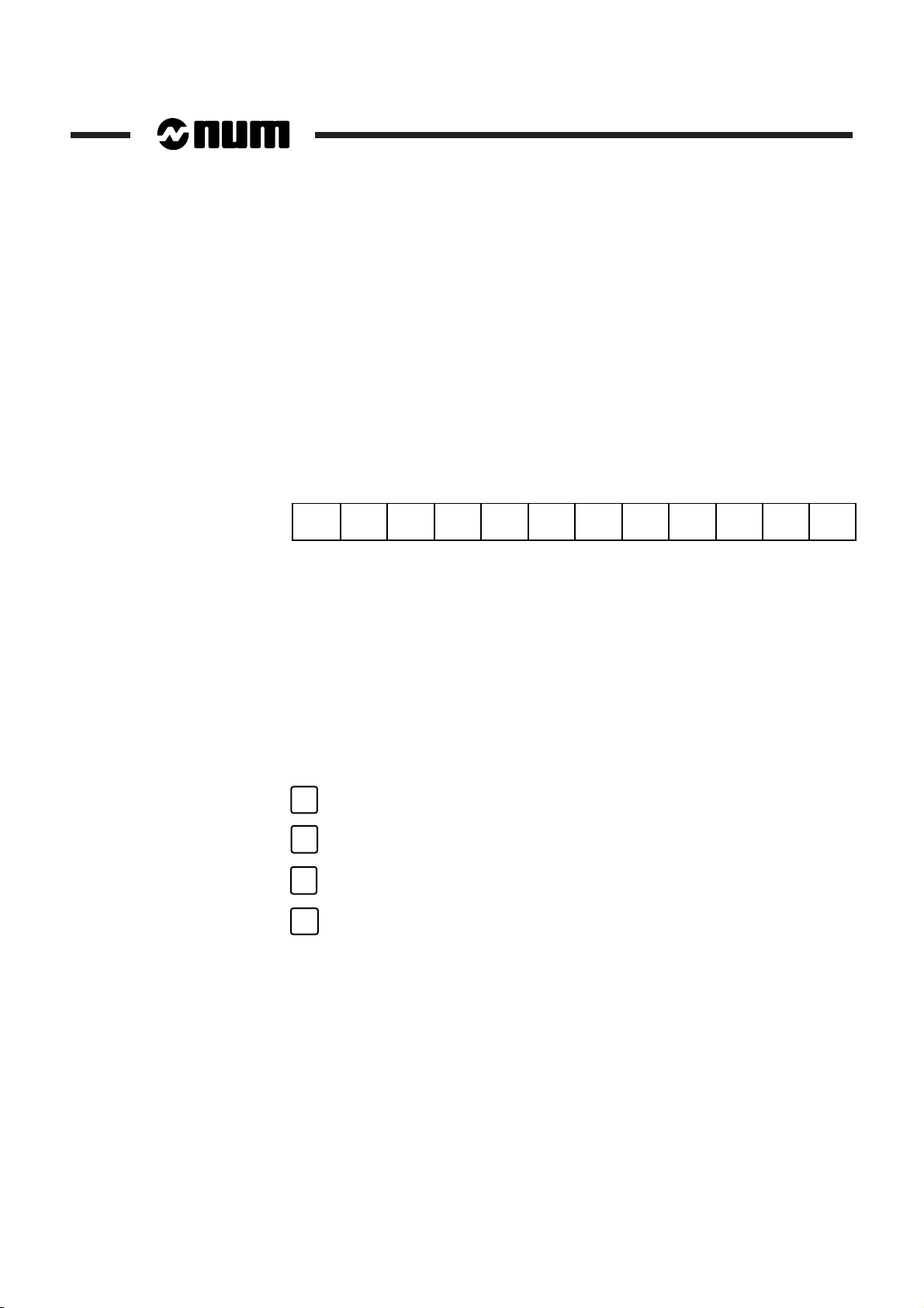
1.3.3.1 Function Keys
Functions keys F1 to F12 are used to choose items proposed in the dialogue window.
F1 F2 F3 F4 F5 F6 F7 F8 F9 F10 F11 F12
1.3.3.2 Cursor Control Keys
When entering values, the cursor control keys are used to select a field or switch
between the fields appearing in the dialogue window.
When editing values, the left and right arrow keys allow you to move around inside
the field selected.
During contour modification, the left and right arrow keys are used to select geometric
elements or intersections on the contour displayed in the graphic window. These
keys are also used to select a contour when several have been created.
Cursor Control Keys
1 - 8 en-938937/0
➞
➞
➞
➞
Page 19
1.3.3.3 Other Keys
General Description of the PROFIL Function
The keys described below are mainly used to enter or modify values or data in fields
displayed in the dialogue window.
Enter Key
This key has several functions:
- It is used to confirm the value entered in a field (after confirmation, the system goes
to the next field)
- It is used to go to the next field when there are several fields in succession
- In certain menus, it has the same function as the confirmation key (generally F10).
Enter key
Field Editing Keys
These keys are used to edit the contents of fields. The field to be edited must first be
selected.
Delete line
Delete last character
INS/
OVER
line
DEL
char
Overwrite/insertion toggle
Delete the character selected
1
1.3.3.1 Notes on Entry of Values
Decimal Values
Decimal values can be entered using either a point or comma as decimal separator.
Negative Values
The minus sign (-) can be entered after entering the value. When confirmed by the
Enter key, the minus sign is placed before the value.
en-938937/0 1 - 9
Page 20

1.3.4 Data or Value Entry Fields
Field Types
The dialogue window may contain fields of different types preceded by their names.
These fields are rectangular.
A distinction is made between:
- Entry fields
- Selection fields.
Entry Field
An entry field allows transfer (or entry) of characters entered on the keyboard or
transfer of predefined data.
Selection Field
This type of field contains a list of data to be selected.
REMARK The data entered (or selected) in the field are highlighted.
Contents of the Fields
Values in Millimetres
Range: 0 to 999999 maximum.
When a value above 999999 is entered, the field is a initialised with the value 0.
Values in Degrees
Range: 0 to 360.
The value must be entered in degrees and thousandths of a degree.
1 - 10 en-938937/0
Page 21

1.4 Coordinate System
The working plane in which the contour is to be created must be defined in the PROFIL
entry page. When the page is confirmed, the plane selected is stored and each
coordinate defining the contour is assigned to the axes of the plane.
Working Planes
Possible working planes:
- X-Y
- Y-Z
- Z-X.
REMARK The working plane selected in the PROFIL entry page cannot be
modified after creating the contour. For parts to be machined in
different working planes, each contour must be created in a separate
subroutine.
General Description of the PROFIL Function
1
en-938937/0 1 - 11
Page 22
1.5 Entering and Exiting from the PROFIL Function
1.5.1 Entering PROFIL
This section describes entry in the PROFIL function. The start of the procedure below
is excerpted from the chapter "Creation of a Part Programme" in the Operator Manual.
REMARK PROFIL is accessible by the edit function in CNC ISO editor bac-
kground mode. PROFIL is not accessible by the CNC edit (EDIT)
mode.
Requirements
Basic softkeys displayed. CNC in Auto, Single, Manual mode or no mode selected.
Actions
Select the "GRAPHIC PROGRAMMING" menu. ☞
The "GRAPHIC PROGRAMMING" menu is displayed.
Select "5 BACKGROUND EDIT". ☞
The message "ENTER PROGRAMME NUMBER" is displayed.
Enter the programme number where the contour is to be described ☞
as "%[programme No.]".
When the programme number is new, the CNC displays the message "CREATE
NEW PROGRAMME? (Y/N).
Confirm creation of a new programme. ☞
Display of: =%[programme No.].
PROCAM
5
Y
REMARK When a programme with the same number exists, the CNC displays the
programme number (e.g. =%50) followed by the blocks it contains.
Enter the PROFIL access letter. ☞
P
1 - 12 en-938937/0
Page 23
Entering PROFIL
General Description of the PROFIL Function
The contents of the page displayed when entering PROFIL differ according to the
1
situation.
The display depends on whether PROFIL is entered from:
- a new programme or an existing programme that does not contain a stored
PROFIL contour, or
- a programme already containing a stored PROFIL contour.
Case of a New Programme or a Programme without PROFIL Contour
PROFIL entry page:
Version 0.90
03.12.93
Plane X-Y
Nb. Profile
Last Pt
Choose: Choose:
Choose:
Choose: Choose:
VerticalVertical
Vertical
VerticalVertical
<--> Choice <--> Choice
<--> Choice
<--> Choice <--> Choice
F10 Next F12 Return F10 Next F12 Return
F10 Next F12 Return
F10 Next F12 Return F10 Next F12 Return
plane plane
plane
plane plane
X-YX-Y
X-Y
X-YX-Y
en-938937/0 1 - 13
Page 24
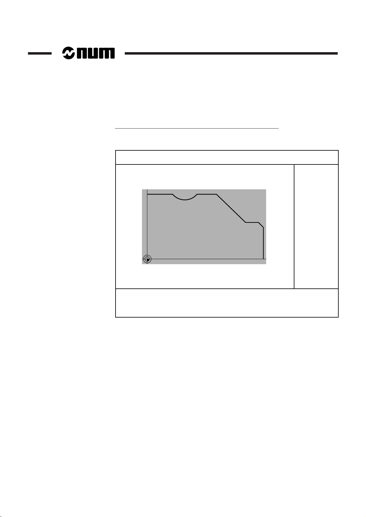
Case of a Programme Containing a Stored PROFIL Contour
Page displaying the graphics of the contour stored:
Version 0.90
03.12.93
X
40
20
Plane X-Y
Nb. Profile 1
Last Pt
- PROFILE - - PROFILE -
- PROFILE -
- PROFILE - - PROFILE -
F1 Creation F5 Deletion F1 Creation F5 Deletion
F1 Creation F5 Deletion
F1 Creation F5 Deletion F1 Creation F5 Deletion
F2 Modification F9 Information F2 Modification F9 Information
F2 Modification F9 Information
F2 Modification F9 Information F2 Modification F9 Information
F4 Geometric transformations <--> Contour choice F4 Geometric transformations <--> Contour choice
F4 Geometric transformations <--> Contour choice
F4 Geometric transformations <--> Contour choice F4 Geometric transformations <--> Contour choice
F10 Save F12 Exit F10 Save F12 Exit
F10 Save F12 Exit
F10 Save F12 Exit F10 Save F12 Exit
0
020406080100
Z
1 - 14 en-938937/0
Page 25
1.5.2 Exiting from PROFIL
General Description of the PROFIL Function
REMARK To prevent accidental exit without saving the contour, PROFIL asks you
1.5.2.1 Example of Exit
REMARK If several contours were created, they are placed one after the other at
PROFIL can only be exited from certain screen pages including a menu. The menu
must include the exit command.
If contour description is active, it is necessary to confirm or abort the description to
access a menu with an exit option.
to confirm before final exit.
Example of exit from the PROFIL page.
Requirements
Page including the "- PROFILE -" menu displayed.
Actions
Select "Exit". ☞
The message "Do you want to quit PROFIL?" is displayed.
Confirm exit from PROFIL. ☞
The page including the programme listing is displayed.
F12
F10
the end of the programme listing.
1
en-938937/0 1 - 15
Page 26

1.6 Contour Numbering
When a new contour is created, the system automatically assigns the lowest
available number by default. This number can be modified immediately or after
saving the contour (range from 1 to 383 maximum).
Renumbering a Contour after Saving It
You can renumber a contour after saving it when the dialogue window containing the
contour identifier is displayed. This window is displayed by selecting the contour in
the graphic window then selecting "Information" in the "- PROFILE -" menu.
Note on Numbering of Contour Copies
When you copy a contour by applying a geometric transformation (see Sec. 2.3),
copies of the contour are created and the smallest available numbers are assigned
by default.
Example: Making three copies of contour No. 3.
If contour numbers 1, 3 and 4 are already assigned, numbers 2, 5 and 6 are assigned
to the three new copies.
1 - 16 en-938937/0
Page 27
General Description of the PROFIL Function
1.7 Calling a Contour Created by PROFIL
To be executable, a numbered contour created by PROFIL must be called. The call
can be made in two different ways:
- By the subroutine call function G77
- From a G63, G64 or G65 machining cycle.
The contour call syntax differs according as the contour was created inside the main
part programme or in a separate subroutine.
1.7.1 Contour Call by Function G77
General Contour Call Syntax by Function G77
G77 [H..] [N.. N..] P.. [S..]
1
G77 Unconditional contour call.
H.. Number of the external subroutine containing the
contour.
N.. N.. Number of the first and last contour block.
P.. Number of the contour created by the PROFIL function.
S.. Number of repetitions of the contour created.
Examples of Contour Calls
Call of a Contour Located in the Main Programme
Single call of contour 1 in the main programme
%200 (MAIN PROGRAMME)
N..
N..
N150 G77 P1
Contour 1 call
N..
N..
#1 G79 N32765
First block of contour 1
G79 N32764 #2
...
...
...
Contour blocks
...
...
N32765 #3
Last block of contour 1
M2
en-938937/0 1 - 17
Page 28

Calling a Contour Located in a Subroutine
Contour 1 in subroutine %301 called twice.
%300 (MAIN PROGRAMME)
N..N..
N..
N90 G77 H301 P1 S2
Contour 1 call
N..
N..
M2
%301 (CONTOUR 1 SUBROUTINE)
#1 G79 N32765
First block of contour 1
G79 N32764 #2
...
...
...
Contour blocks
...
...
...
N32765 #3
Last block of contour 1
REMARK If using block numbers N.. N.., the contour start and end block numbers
must be specified by the user.
1 - 18 en-938937/0
Calling Several Contours Located in the Same Subroutine
%400 (MAIN PROGRAMME)
N..
N..
N90 G77 H401 P1
Contour 1 call
N..
N200 G77 H401 P2 S2
Contour 2 call
N..
N500 G77 H401 P3 S5
Contour 3 call
N..
M2
Page 29

General Description of the PROFIL Function
1.7.2 Calling a Contour from a Machining Cycle
General Contour Call Syntax from a Machining Cycle
G63/G64/G65 [H..] [N.. N..] / [EP..] (other arguments of the cycle)
G63/G64/G65 Machining cycle call function.
H.. Number of the external subroutine containing the
contour.
N.. N.. Numbers of the first and last contour blocks (equivalent
to a call by EP..).
EP.. Number of the contour created by the PROFIL function
(equivalent to a call by N.. N..).
Example of Contour Call
Contour Call from a Cycle
Calling of contour 1 located in the main programme.
%600 (MAIN PROGRAMME)
N..
N..
N..
N150 G64 EP1 I.. K.. P..
Contour 1 call
N..
N..
N..
#1 G79 N32765
First block of contour 1
G79 N32764 #2
...
...
...
Contour blocks
...
...
N32765 #3
Last block of contour 1
M2
1
REMARK For the other syntaxes used to call a contour from a cycle, refer to the
examples given for function G77 (see Sec. 1.7.1).
en-938937/0 1 - 19
Page 30

1.8 Description of the Programme Generated by PROFIL
When a contour is created by PROFIL, the software converts the graphically
generated contour to an entity.
CAUTION
!
The entity generated cannot be directly modified in ISO language. Any modification
concerning a contour must be made using the "Modification" option in the "PROFIL" menu.
1.8.1 Description of an Entity
The contour contained in the entity is saved as interpolations by ISO codes G1, G2
and G3 followed by values.
The general information concerning the contour is stored after the entity header and
is used to save:
- The working plane
- The minimum window size
- The contour type (irregular, rectangle, circle or polygon).
Entity
#1 G79 N(2i+1)
N(2i),#2,
N(x),#200,(PROFIL PROFIL,No., comment,) ($D,N˚,M2)
N(x+1)
N(x+2)
N(x+3)
N(x+4)
N(2i+1),#3,
#(XY PLANE)
#(MACRO)
#(INFO.)
#ISO code G1, G2, G3
1 - 20 en-938937/0
Information on the Entity
In the entity, the "," characters represent tabs (value 0x09). These characters are
used by the interactive programme interpreter and must not be omitted.
2i: Number of the first block in the entity
The first entity block number selected by the user determines the contour entry point.
This point is calculated from the entity number.
Example: 2i = 32766-2n (where n is the entity number).
x: Number of the first PROFIL block
The first PROFIL block number is specified by the user when creating the contour by
PROFIL.
Page 31

1.8.2 Structure of a Programme Generated
General Description of the PROFIL Function
#1 G79 N32765
N32764 #2
N10 #200 (PROFIL PROFIL 1 MILLING) ($D 1 M2)
N11 # 210
N12 # (XY plane)
N13 # ...
N14 # ...
N15 # ...
N16 # ...
N32764 #3
Working plane
Contour in G1, G2 or G3 and coordinates
1
en-938937/0 1 - 21
Page 32

1 - 22 en-938937/0
Page 33

Creating and Editing Contours
2 Creating and Editing Contours
2.1 Contour Types 2 - 3
2.1.1 Irregular Contours 2 - 3
2.1.2 Contours with Predefined Shapes 2 - 3
2.1.2.1 Rectangle 2 - 4
2.1.2.2 Circle 2 - 5
2.1.2.3 Polygon 2 - 5
2.2 Geometric Elements and Construction Aid Tools 2 - 7
2.2.1 General 2 - 7
2.2.2 Geometric Elements for Contour
Construction 2 - 7
2.2.2.1 Notes on Use of Geometric Elements 2 - 7
2.2.2.2 Line 2 - 9
2.2.2.3 Arc 2 - 10
2.2.2.4 Line/Line 2 - 12
2.2.2.5 Line/Arc 2 - 13
2.2.2.6 Arc/Line 2 - 14
2.2.2.7 Arc/Arc 2 - 15
2.2.2.8 Line/Line/Arc 2 - 16
2.2.2.9 Line/Arc/Arc 2 - 16
2.2.2.10 Arc/Line/Arc 2 - 17
2.2.2.11 Arc/Arc/Arc 2 - 18
2.2.3 Construction Aid Tools 2 - 19
2.2.3.1 Fillet/Chamfer 2 - 19
2.2.3.2 Geometry 2 - 22
2.2.3.3 Deletion 2 - 22
2.2.3.4 Last Element 2 - 24
2.2.3.5 Zoom 2 - 24
2.2.3.6 Change Direction 2 - 25
2.2.3.7 Calculator 2 - 25
2.2.3.7 Determination 2 - 27
2.3 Geometric Transformation Tools 2 - 30
2.3.1 Possibilities of Geometric Transformations 2 - 30
2.3.1.1 Shift 2 - 30
2.3.1.2 Rotation 2 - 31
2.3.1.3 Mirror 2 - 32
2.3.1.4 Scaling Factor 2 - 34
2.4 Miscellaneous Tools 2 - 35
2.4.1 Disengage Object 2 - 35
2.4.2 Confirming and Saving a Contour After
Creation 2 - 36
2.4.3 Contour Choice 2 - 37
2
en-938937/0 2 - 1
Page 34

2 - 2 en-938937/0
Page 35

2.1 Contour Types
Creating and Editing Contours
The sections below describe the capabilities offered by PROFIL for creating and
modifying contours, i.e.:
- The types of contours that can be drawn by PROFIL
- The geometric elements and tools used during contour creation
- The geometric transformations that can be applied to the contours created
- The special tools available for creating contours.
The following types of contours can be created with PROFIL:
- Irregular contours
- Contours with predefined shapes (rectangle, circle, polygon).
It should be noted that some of the contour creation possibilities described are
common for turning and milling and others are specific to either turning or milling.
2
X-Axis Value Entry in Turning Mode
Depending on the type of programming declared for a turning type machine (see
parameter P4), the values on the X axis can be entered with reference to the diameter
or radius.
2.1.1 Irregular Contours
Irregular or freehand contours are constructed as a sequence of geometric line or arc
elements. Fillets and chamfers can be applied to the intersections between elements
(see the section "Elements and Tools for Contour Creation").
Irregular contours can be open or closed. They can be modified during or after
creation.
2.1.2 Contours with Predefined Shapes
Macros are provided for the following predefined contour shapes:
- Rectangle
- Circle
- Polygon.
These contours are closed. Rectangular and polygonal contours can include
chamfers and fillets at the intersections of their sides.
After creation, a contour can be modified to transform it into an irregular contour. The
transformation can be carried out by the function "Disengage object" (see below) for
a contour that has just been created or by the "Modification" function for a contour that
is stored.
en-938937/0 2 - 3
Page 36

2.1.2.1 Rectangle
Angle
Reference point
Y
X
Definition Data
The rectangle definition data are as follows:
- Width
- Length
- Angle
- Radius.
Description of Rectangle Data
Length and Width
The length is defined with respect to the X axis and the width with respect to the Y (or
Z) axis depending on the working plane selected. If the angle is 0, the rectangle length
is parallel to the X axis.
Angle
The rectangle can be pivoted by entering an angle (positive in the counterclockwise
direction). The rectangle is rotated around the reference point declared after
confirming the definition data.
Radius
When a value is entered in the "Radius" field, four equal radii are applied to the four
corners of the rectangle.
Rectangle Reference Point and Position
After confirming the dimensions, the software prompts for definition and location of
the reference point. If an angle was defined, the angular rotation is referenced to this
point.
Five reference points are possible:
- Bottom left corner (lower left limit)
- Bottom right corner (lower right limit)
- Top left corner (upper left limit)
- Top right corner (upper right limit)
- Centre.
For instance, in the figure opposite, the
rectangle is rotated around the bottom
left corner.
2 - 4 en-938937/0
Page 37

2.1.2.2 Circle
Creating and Editing Contours
Definition Data
A circle is defined by its diameter.
2.1.2.3 Polygon
Circle Position and Reference
After confirmation of the diameter, the circle position is defined with respect to its
centre point.
Definition Data
The polygon definition data are as follows:
- Number of sides
- Side length/length across flats (entry side)/length across points (overshoot)
- Angle
- Radius.
Description of Polygon Data
Number of sides
The polygon can have from 3 to a maximum of 99 sides.
Side length/length across flats/length across points
Depending on its dimensions, the polygon can be defined by one of the three following
dimensional parameters:
- Side length
- Length across flats (entry side)
- Length across points (overshoot).
2
The required dimension, i.e. side length, length across flats or length across points,
is selected by left/right arrow keys. These three parameters are interdependent
(when one of them is entered, the other two are calculated automatically by the
software).
en-938937/0 2 - 5
Page 38

Dimensioning of polygons:
Length across points
0°
Y
X
Length across flats
0°
Y
X
Angle
Dimensioning with an odd number Dimensioning with an even number
of sides of sides
Side length
0°
Y
X
Angle
The polygon can be positioned by entering an angular value (positive in the
counterclockwise direction) with respect to the reference axis. The polygon is then
rotated around the centre.
Example:
- Rotation with respect to the X axis.
Radius
When a value is entered in the Radius field, the polygon is assigned radii of the same
length in each angle.
Polygon Reference Position
After confirming the dimensions, the position of the polygon is defined with respect
to its centre.
2 - 6 en-938937/0
Page 39

Creating and Editing Contours
2.2 Geometric Elements and Construction Aid Tools
2.2.1 General
When creating or modifying a contour, the user can access geometric elements and
tools to help with construction.
The geometric elements and construction aid tools are as follows:
- Line
- Circle
- Chamfer/fillet
- Geometry
- Deletion
- Last element
- Zoom
- Change of direction
- Calculator
- Determination.
2
Reminder
During construction, only the commands in boldface characters are available.
2.2.2 Geometric Elements for Contour Construction
The geometric elements are as follows:
- Line
- Circle.
2.2.2.1 Notes on Use of Geometric Elements
Definition of Elements and Sequences
The possibilities for constructing contours using line and circle geometric elements
are described below with reference to figures and tables. The data are given for the
XY plane, but can be adapted for the other working planes (ZX or YZ).
The number of solutions allowing connections between elements to be defined varies
according to the configuration of the sequence. The software proposes solutions (the
number of solutions per sequencing case is given in the tables below).
In all the cases of construction illustrated, the start point "D" of the element or
sequence is known.
An intermediate circle is displayed in certain sequences including arcs. In the case
of a CNC with colour screen, this intermediate circle is red (if the colour was not
changed in the colour palette). For the definition cases covered below, the
intermediate circle is shown as a thin line and the arc as a boldface line.
en-938937/0 2 - 7
Page 40

Information on Geometric Elements for Contour Construction
+
–
Tangent line/circle elements
A sequence of a line and a circle can be
defined as:
- Tangent without reversal
- Tangent with reversal.
Circle definition direction
When constructing a contour, the direc-
tion in which a circle is defined is specified
as:
- Clockwise, or
- Counterclockwise.
Without reversal
With reversal
Counterclockwise
2 - 8 en-938937/0
Clockwise
Line angle
The positive or negative angle of a line is
identified trigonometrically. The value of
the angle is defined with respect to the
reference axis (X in the XY plane and Z
in the ZX plane).
Page 41

2.2.2.2 Line
L
A
X - Y
D
Nontangent Line
Definition data of the line opposite:
- X: End point in X
- Y: End point in Y
- L: Length
- A: Angle
Definition Solutions X Y L A
11xx
Creating and Editing Contours
2
2 1 or 2 x x
3 1 or 2 x x
41x x
51xx
62 xx
Tangent Line
For tangent lines, definitions 4, 5 and 6 of the table above (nontangent line) can be
used if angle A is known.
en-938937/0 2 - 9
Page 42

2.2.2.3 Arc
R
D
X-Y
Xc-Yc
Nontangent Arc
Definition data of the arc opposite:
- R: Arc radius
- Xc: Arc centre in X
- Yc: Arc centre in Y
- X: End point in X
- Y: End point in Y
- Xe: Extreme X coord.
- Ye: Extreme Y coord.
Definition Solutions R Xc Yc X Y Xe Ye
11xx
2 1 or 2 x x x
3 1 or 2 x x x
4 1 or 2 x x x
Tangent Arc
Definition data of the arc opposite:
- R: Arc radius
- Xc: Arc centre in X
- Yc: Arc centre in Y
- X: End point in X
- Y: End point in Y
Ye
X-Y
R
D
Xc-Yc
Xe
2 - 10 en-938937/0
Definition Solutions R Xc Yc X Y
12xx
21x
31 x
41 xx
Page 43

Other Type of Tangent Arc
D
X-Y
Ao
At
Definition data of the arc opposite:
- X: End point in X
- Y: End point in Y
- Ao: Aperture angle
- At: Tangent in the end point
In this case, parameters Ao and At can
only be used when the intermediate circle
is displayed.
Creating and Editing Contours
2
Definition Solutions X Y Ao At
1 1 or 2 x
2 1 or 2 x
31 x
41 x
en-938937/0 2 - 11
Page 44

2.2.2.4 Line/Line
L1
A1
A2
X1-Y1
X2-Y2
D
L2
Nontangent Line/Nontangent Line
Definition data of the sequence opposite:
-X
-Y
-L
-A
: End point in X
(1-2)
: End point in Y
(1-2)
: Length
(1-2)
: Angle
(1-2)
Definition Solutions X1Y1L1A1X2Y2L2A
2
1 1 or 2 x x x x
2 1 or 2 x x x x
3 1 or 2 x x x x
41x xxx
5 1 or 2 x x x x
6 1 or 2 x x x x
7 1 xxxx
8 1 xxx x
Tangent Line/Nontangent Line
For a tangent line followed by a nontangent line, definitions 7 and 8 of the table above
(nontangent line/nontangent line) can be used if angle A1 is known.
2 - 12 en-938937/0
Page 45

2.2.2.5 Line/Arc
R
Xc-Yc
A
D
A
D
R
At
Xc-Yc
X-Y
Nontangent Line/Nontangent Arc
Definition data of the sequence opposite:
- A: Angle
- R: Arc radius
- Xc: Arc centre in X
- Yc: Arc centre in Y
Nontangent Line/Nontangent Line
Creating and Editing Contours
2
Definition Solutions A R Xc Yc
1 2 xxxx
Definition data of the sequence opposite:
- A: Angle
- R: Arc radius
- Xc: Arc centre in X
- Yc: Arc centre in Y
- X: Arc end point in X
- Y: Arc end point in Y
- At: Arc tangent in end point
Nontangent Line/Tangent Arc
Definition Solutions A R Xc Yc X Y At
2 1 or 2 x x x
3 1 or 2 x x x x
4 1 or 2 x x x x
5 1 or 2 x x x x
Tangent Line/Tangent Arc
During tangent line/tangent arc sequences, definitions 1, 3 and 5 of the tables above
can be used if angle A is known.
en-938937/0 2 - 13
Page 46

2.2.2.6 Arc/Line
X-Y
R
D
A
X-Y
A
D
X-Y
D
Nontangent Arc/Tangent Line
Definition data of the sequence opposite:
- R: Arc radius
- X: End point in X
- Y: End point in Y
- A: Angle
Definition Solutions R X Y A
1 1 or 2 x x x x
Nontangent Arc/Nontangent Line
Definition data of the sequence opposite:
- A: Angle
- X: End point in X
- Y: End point in Y
In this case, the data can only be used
when the intermediate circle is displayed.
2 - 14 en-938937/0
Definition Solutions A X Y
1 1 or 2 x x x
Nontangent Arc/Nontangent Line
Definition data of the sequence opposite:
- X: End point in X
- Y: End point in Y
In this case, the data can only be used
when the intermediate circle is displayed.
Definition Solutions Xc
1 1 or 2 x x
Page 47

2.2.2.7 Arc/Arc
Xc-Yc
D
R
At
X-Y
D
R
Arc/Nontangent Arc
Definition data of the sequence opposite:
- R: Arc radius
- X: End point in X
- Y: End point in Y
In this case, the data can only be used
when the intermediate circle is displayed.
Definition Solutions R X Y A
1 1 or 2 x x x x
Creating and Editing Contours
2
Arc/Tangent Arc
Definition data of the sequence opposite:
- Xc: Arc centre in X
- Yc: Arc centre in Y
- R: Arc radius
- X: End point in X
- Y: End point in Y
- At: Arc angent in end point
In this case, the data can only be used
when the intermediate circle is displayed.
Definition Solutions Xc Yc R X Y At
2 1 or 2 x x
3 1 to 4 x x x
4 1 to 4 x x x
5 1 to 4 x x x
en-938937/0 2 - 15
Page 48

2.2.2.8 Line/Line/Arc
A1
D
A2
Xc-Yc
R
A
D
R1
Xc-Yc
R2
2.2.2.9 Line/Arc/Arc
Nontangent Line/Line/Tangent Arc
Definition data of the sequence opposite:
- A(1-2): Angle
- Xc: Arc centre in X
- Yc: Arc centre in Y
- R: Arc radius
Definition Solutions A1A2Xc Yc R
1 1 or 2 x x x x x
Tangent Line/Line/Tangent Arc
During a sequence of tangent line/line/tangent arc, the definition of the table above
is applicable if angle A1 is determined from the tangent sequence.
Nontangent Line/Tangent Arc/Tangent Arc
2 - 16 en-938937/0
Definition data of the sequence opposite:
- A: Angle
- R(1-2): Arc radius
- Xc: Arc centre in X
- Yc: Arc centre in Y
Definition Solutions A R1Xc Yc R
2
1 2 to 8 x x x x x
Tangent Line/Tangent Arc/Tangent Arc
During a sequence of a tangent line/arc/tangent arc, the definition of the table above
is applicable if angle A1 is determined from the tangent sequence.
Page 49

2.2.2.10 Arc/Line/Arc
D
R
Xc-Yc
A
Arc/Nontangent Line/Tangent Arc
Definition data of the sequence opposite:
- A: Angle
- Xc: Arc centre in X
- Yc: Arc centre in Y
- R: Arc radius
In this case, the data can only be used
when the intermediate circle is displayed.
Definition Solutions A Xc Yc R
Creating and Editing Contours
2
1 2 to 4 x x x x
Arc/Tangent Line/Tangent Arc
Definition data of the sequence opposite:
- Xc: Arc centre in X
- Yc: Arc centre in Y
- R: Arc radius
In this case, the data can only be used
when the intermediate circle is displayed.
Definition Solutions Xc Yc R
1 2 to 4 x x x
R
Xc-Yc
D
en-938937/0 2 - 17
Page 50

2.2.2.11 Arc/Arc/Arc
Xc-Yc
D
R1
R2
Arc/Tangent Arc/Tangent Arc
Definition data of the sequence opposite:
-R
: Arc radius
(1-2)
- Xc: Arc centre in X
- Yc: Arc centre in Y
In this case, the data can only be used
when the intermediate circle is displayed.
Definition Solutions R1Xc Yc R
1 1 to 8 x x x x
2
2 - 18 en-938937/0
Page 51

2.2.3 Construction Aid Tools
The construction aid tools are as follows:
- Fillet/Chamfer
- Geometry
- Deletion
- Last element
- Zoom
- Change of direction
- Calculator
- Determination.
Reminder
When creating or modifying a contour, only the commands displayed in boldface
characters can be selected.
Creating and Editing Contours
2
2.2.3.1 Fillet/Chamfer
You can select the Radius(Fillet)/Chamfer command to insert a fillet or chamfer
between geometric elements. The fillet and chamfer are considered respectively as
an arc and a line. They can only be inserted at the intersection between two elements
already constructed.
The location where the fillet or chamfer is to be inserted is selected with the left/right
arrow keys (to move the square onto the intersection).
A chamfer or a fillet can only be inserted between secant elements or tangent
elements with change of direction.
Fillet/Chamfer Definition Data
Fillet
A fillet is defined by its radius.
Chamfer
The chamfer definition data are as follows:
- Width
- Length
- Width and angle.
en-938937/0 2 - 19
Page 52

Description of the Fillet
Inserted fillet
Theoretical intersection
ab
c
Radius
In all cases the radius specified for the fillet must always allow a tangent connection
between the elements where the fillet is inserted.
A fillet can be inserted between the
following elements:
- Line/line (case 1)
- Arc/arc (case 2)
- Line/arc (case 3).
Case 1
a
R
Case 2
Point "a" is the point of intersection
between the two elements where the
Case 3
a
fillet is to be inserted.
a
R
R
Notes on constructions with a fillet
In certain cases of construction, it is not always possible to create an arc by the Circle
command of the menu used for creation, because the theoretical intersection
between the two elements cannot be used during construction. This case of
connection can be solved by inserting a fillet.
Example:
- Construction of the part of the contour
(points a-b-c) as though there where
no intermediate connection
- Then, insertion of the fillet in the
theoretical point of intersection (b).
2 - 20 en-938937/0
Description of Chamfer Data
In all cases, the dimension assigned to the chamfer must not be greater than the
length of the smallest of the lines between which the chamfer is inserted.
In certain cases, a chamfer can be inserted between two lines, one of which was
already created by insertion of a chamfer.
Page 53

Length
Length
a
a
Case 1
a
Width
Case 3
a
Width
Case 2
Width
Angle
Width
Angle
Width
Point "a": Point of intersection between
the two lines where the chamfer is
inserted.
The two points where the chamfer is
connected are at an equal distance from
point "a".
Creating and Editing Contours
2
Width
The width of the chamfer applies to the
following cases of insertion:
- line/line (case 1)
- arc/arc (case 2)
- line/arc (case 3).
Point "a": Point of intersection between
the two elements where the chamfer is to
be inserted.
Width and Angle
In this case, the software proposes two
solutions after the width and angle have
been confirmed.
en-938937/0 2 - 21
Page 54

2.2.3.2 Geometry
The Geometry command can be selected to display the characteristics concerning
the geometric element selected (line or circle). These characteristics are displayed
in the data window.
The geometric element is selected with the arrow keys (left/right).
Characteristics of a Line or a Circle
Line
Characteristics of a line selected:
- Start point
- End point
- Length
- Angle with respect to the abscissa.
Circle
Characteristics of a circle selected:
- Start point
- End point
- Centre
- Radius
- Entrance angle
- Exit angle
- Aperture
- Length of the arc.
2.2.3.3 Deletion
2 - 22 en-938937/0
The Deletion command can be selected to delete the geometric element (line or
circle) selected on the contour.
The element to be deleted is selected with the arrow keys (left/right).
When an intermediate geometric element was deleted during construction of a
contour, it is impossible to add interposed elements independent of the contour. It
is therefore necessary to restore the interrupted sequence and reconstruct a single
contour.
Page 55

Creating and Editing Contours
Element deleted
by Deletion
Connection by
End chaining
Element deleted
by Deletion
Connection by
XY Shift
Deletion Possibilities
After selecting and deleting an element, the software proposes the following
possibilities:
- End chaining
- Shift in X and Y direction
- Shift in X direction
- Shift in Y direction
- Continue with one of the contours
- Continue with an open contour.
Description of the Deletion Subcommands
End chaining
2
This command causes lengthening or
shortening of the adjacent geometric
elements to restore the connection
between the separated parts of the contour.
Case of an open or closed contour.
Shift in X and Y direction
This command defines the X and Y shift
of one of the parts of the contour to
restore the connection between the
separated parts.
This command applies to an open contour.
Shift in X direction
Same as shift in XY direction but on X only.
en-938937/0 2 - 23
Page 56

2.2.3.4 Last Element
2.2.3.5 Zoom
Shit on Y direction
Same as shift in XY direction but on Y only.
Continue with one of the contours
This command is used to delete one of the parts of the contour made independent
by deletion of a geometric element. After selecting the part to be kept, the other part
is deleted. A new replacement element can then be created.
This command applies to an open contour.
Continue with an open contour
This command defines the end of the contour where the new element can be
constructed (end selected by Change direction).
This command applies to a closed contour. Otherwise, deletion of an element causes
the contour to be separated into two contours.
The Last element command displays the values entered to construct the last
geometric element created in the dialogue window. These values can be modified.
The Zoom command is used to enlarge or reduce part of the contour.
The Zoom command causes display of a rectangular zoom window in the graphic
window. The zoom window can be moved and the contour zone selected using the
arrow keys (left/right).
Zoom Possibilities
The following possibilities are available for defining a zoom:
- Reduce the window
- Enlarge the window
- Zoom on last element
- Full view.
Description of Zoom Possibilities
Reduce the window
This command decreases the zoom window displayed. The size is decreased by
pressing the Reduce the window function key the number of times required.
2 - 24 en-938937/0
Page 57

Creating and Editing Contours
Enlarge the window
This command enlarges the zoom window displayed. The window is enlarged by
pressing the Enlarge the window function key the number of times required.
The maximum enlargement is 1000 times.
Zoom on the last element
This command automatically zooms on the last element of the contour.
Full view
After using the zoom command, this command is used to return to the full view of the
contour in the graphic window.
2
2.2.3.6 Change Direction
The Change direction command is used to go from one end to the other of the contour
displayed in order to change the direction of construction. This function applies only
to open contours.
When a change of direction is defined in the description of the contour, this command
reverses the direction during simulation.
2.2.3.7 Calculator
The Calculator command displays the calculator integrated in the software for
calculating values. This function is available only when inserting the coordinates of
a point on the contour.
General
The calculator performs operations on numbers with up to five digits before and three
after the decimal point. The result of an operation can be rounded off by the software
when there are more than three decimal digits.
Basic operations
+: Addition
-: Subtraction
*: Multiplication
: or /: Division
Brackets
( and ): Brackets are placed around the operations to be performed first.
en-938937/0 2 - 25
Page 58

Correcting the values entered
The values entered can be corrected using the same keys as for correction of data
in the fields.
Numerical values
0-9: Entry of numerical values.
Decimal values
, or .: Possible decimal separators.
Values in degrees/minutes/seconds
Angular values in degrees/minutes/seconds must be entered in decimal form.
Example: Enter 3.1238 for 3˚12’38".
Next and Return keys
The Next key transfers the result into the field selected before calling the calculator.
Return is used to exit from use of the calculator.
Calculator Functions
When you select the Calculator, the software proposes the following functions:
- Square root
- x^y
- Cancel
-PI
- Trig functions
- Memory.
2 - 26 en-938937/0
Description of Calculator Functions
Square root
Square root of a number.
x^y
Exponent of a number.
Cancel
Total deletion of the value displayed in the field.
PI
Inserts the value 3.141593.
Page 59

Creating and Editing Contours
Trig functions
The Trig functions command gives access to the following list:
- SIN : Sine
- ARCSIN : Arc sine
- COS : Cosine
- ARCCOS : Arc cosine
- TAN : Tangent
- ARCTAN : Arc tangent
- GRAD -> DEG : Change from grades to degrees
- DEG -> GRAD : Change from degrees to grades
REMARK In the above list, operations such as square root and trigonometric
functions must end with a bracket.
2
2.2.3.7 Determination
Memory
Storage and recall of stored values.
The Memory command gives access to the list of memories (MEM: memory) and
recall of stored values (RCL: recall):
- MEM1 RCL1
- MEM2 RCL2
- MEM3 RCL3
- MEM4 RCL4
The Determination command determines one or more values on the part of a
geometric element (line or circle) already constructed. This function is not active until
the coordinates of a point on the contour including at least two geometric elements
have been entered.
Determination Possibilities
After selection of Determination, the display in the dialogue window allows selection
of the type of point:
- End point
- Centre
- Distant point
- X intersection point
- Y intersection point.
After selecting a type of point, the possible restart point on the contour is selected with
the arrow keys (left/right).
en-938937/0 2 - 27
Page 60

Description of the Possibilities of Determination
d
d
a
d
d
a
c
d
d
a
d
d
a
c
Determination of points on a line
Points on the line opposite:
- End point (a)
- Centre (c)
- Distant point (d)
Determination of points on an arc
Points on the arc opposite:
- End point (a)
- Centre (c)
- Distant point (d)
2 - 28 en-938937/0
Page 61

Creating and Editing Contours
Determination of X intersection point and Y intersection point
After you choose X intersection point or Y intersection point, the software creates an
imaginary line at the X or Y distance entered. One or more geometric elements can
be intersected by this line. The point intersecting the element selected is selected
with the arrow keys (left/right).
Line Circle
Y Intersection point
Y Intersection point
2
X Intersection point
X Intersection point
en-938937/0 2 - 29
Page 62

2.3 Geometric Transformation Tools
Y
X
20
25
2.3.1 Possibilities of Geometric Transformations
PROFIL can be used to perform the following transformations on a contour after
creation:
- Shift
- Rotation
- Mirror
- Scaling factor.
After construction, the contour must be selected and confirmed in order for the
geometric transformation(s) to be applied to it.
When the data required for the transformation have been entered and confirmed, the
software proposes to copy the original contour and asks for the number of copies to
be made. The original contour can be kept by copying it (see Sec. 1.6 for notes on
contour copy numbers).
When a contour is copied such that each end point of the original contour corresponds
to the start point of the next copy, the new contour created is listed under the same
number as the original contour (this case is possible for shift, rotation and mirror).
2.3.1.1 Shift
Definition Data
The contour shift definition data are as follows:
- Shifting by a value
- Shifting of a point of the contour to a specific point.
Description of Shift Data
Shifting by a value
The original contour is shifted incrementally on the X and Y coordinates.
Example:
- Shifting of the original contour by X20
and Y25.
2 - 30 en-938937/0
Page 63

Creating and Editing Contours
Y
X
90°
P
Shifting of a point on the contour to a given point
In this case, it is necessary to define a reference point on the original contour then the
absolute coordinates of the point where it is to be shifted.
Example:
- Reference point P located at X15 and
Y5
- Point shifted to X35 and Y30.
35
P
Y30
2
2.3.1.2 Rotation
Y
P
X
Definition Data
The contour rotation definition data are as follows:
- Rotation reference point
- Value of the angle of rotation.
Description of Rotation Data
Rotation reference point
The X and Y coordinates of the reference point are entered.
There are two possibilities for the position of the rotation reference point:
- Rotation point located on the contour
- Rotation point located off the contour.
Example of rotation point located on the
contour:
- Reference point P at X25 and Y25
(absolute)
- Rotation by 90 degrees around point
P.
en-938937/0 2 - 31
Page 64

Y
X
90°
P
2.3.1.3 Mirror
Example of rotation point located off the
contour:
- Reference point P located at X25 and
Y25 (absolute)
- Rotation by 90 degrees around point
P.
Definition Possibilities
The mirror definition possibilities that can be applied to a contour are as follows:
- X mirroring
- Y mirroring
- X and Y mirroring.
Description of Mirror Possibilities
After selecting the type of mirroring (X, Y or XY), the mirror may be shifted on the
mirroring axis (shift with respect to the reference point). If no shift is to be applied, it
is necessary to enter the value 0.
X Mirroring
Mirroring on the X axis is applied with
respect to an axis parallel to the Y axis.
Mirror axis
X
Y
X
2 - 32 en-938937/0
Page 65

Y Mirroring
Y
X
Y
Mirror axis
Y
X
X-Y
Mirroring on the Y axis is applied with
respect to an axis parallel to the X axis.
Creating and Editing Contours
2
X and Y Mirroring
Mirroring on the Y axis is applied with
respect to an axis parallel to the X axis.
Mirroring on the X axis is applied with
respect to an axis parallel to the Y axis.
en-938937/0 2 - 33
Page 66

2.3.1.4 Scaling Factor
Definition Data
The data applying a scaling factor to a contour are as follows:
- Fixed point
- Scaling factor.
Description of Scaling Factor Data
Fixed point
The contour is enlarged or reduced with respect to a fixed point whose X and Y
coordinates must be entered before the scaling factor.
Scaling factor
When a scaling factor is applied to a contour, the original dimensions of the contour
are modified.
Possibilities:
- Factor greater than 1: Contour enlarged (maximum factor 1000)
- Factor less than 1: Contour reduced (minimum factor 0.001).
Example:
- Fixed point P at X25 and Y25
- Scaling factor = 2.
2 - 34 en-938937/0
Y
X
Page 67

2.4 Miscellaneous Tools
2.4.1 Disengage Object
The Disengage object command is mainly used to modify a contour with a predefined
shape (rectangle, circle, polygon).
The Disengage object function is not available until contour creation has been
confirmed (without exiting from PROFIL).
Accessing and Selecting Disengage Object
When the contour with a predefined shape that has just been created is displayed,
selecting Modification causes display of the contour dimensions. The Disengage
object function is available.
Creating and Editing Contours
2
When you select Disengage object, the "Profile" menu is displayed. You must then
select Modification again.
The contour is displayed with the square marker moved on geometric elements using
the arrow keys (left/right).
Possibilities of the Disengage Object Function
The following possibilities are available:
- Line
- Circle
- Geometry
- Deletion
- Zoom
- Change direction.
Description of the Disengage Object Commands
Notes on Line and Circle
Two case can occur:
- The contour with a predefined shape has not been modified and is still a closed
contour
- The contour with a predefined shape has been modified by deletion of one of its
elements (see Deletion) and has become an open contour.
Closed contour: In this case, the start of the line or circle to be defined is the origin
of the contour with the predefined shape.
Open contour: In this case, the start of the line or circle can be one of the ends of the
open contour.
REMARK The other commands in this menu are used in the same way as
described above.
en-938937/0 2 - 35
Page 68

2.4.2 Confirming and Saving a Contour After Creation
After creating a contour and confirming it by the Confirm key, the Profile menu is
displayed in the dialogue window.
Possibilities after Confirming the Contour
The following commands are available:
- Creation
- Modification
- Geometric transformations
- Deletion
- Information
- Save.
Description of Commands after Confirming
Creation
The Creation command is used to create a new contour with the same programme
number without exiting from the PROFIL function.
Modification
The Modification command is used to display and possibly modify a contour already
created.
Geometric transformations
The Geometric transformations command is used to apply geometric transformations
to the contour.
Deletion
The Deletion command is used to delete the contour selected.
If several contours are defined in the same programme, the contour to be deleted is
selected with the arrow keys (left/right).
Information
The Information command is used to edit the instructions identifying the contour
selected (Number, First Nxx, Comment).
Save
The Save command is used to save the contour created. PROFIL always asks you
to confirm that you want to exit to avoid exiting involuntarily without saving the
contour.
Once you confirm exit, the programme containing the contour definition is displayed
(the programme generated cannot be edited).
2 - 36 en-938937/0
Page 69

2.4.3 Contour Choice
Creating and Editing Contours
The Contour Choice command is available only when several contours are displayed
(contours created with the same programme number). You can select one of the
contours to view the information concerning it or modify it, etc.
The contour is selected with the arrow keys (left/right).
2
en-938937/0 2 - 37
Page 70

2 - 38 en-938937/0
Page 71

Examples of Contour Creation
3 Examples of Contour Creation
3.1 Example of Milled Workpiece 3 - 3
3.2 Creating a Milled Workpiece Contour 3 - 4
3.3 Example of Turned Workpiece 3 - 10
3.4 Creating a Turned Workpiece Contour 3 - 11
3
en-938937/0 3 - 1
Page 72

3 - 2 en-938937/0
Page 73

Examples of Contour Creation
10
90
10
R15
5 at 45°
65
e
f
d
c
b
a
a'
5
15
4 0
130°
Y
XOP
10 5
Z
The examples below are designed to give:
- A method for starting to create contours
- An overview of the possibilities for creating contours with PROFIL.
Each example includes:
- Information concerning creation of the contour
- A sketch illustrating the contour.
3.1 Example of Milled Workpiece
Contour Definition Data
Contour No. 1
Contour name: Milled contour 1
Parallelepiped dimensions: 95 x 45 x 15
Working plane: XY
Contour points: a-b-c-d-e-f-a’
Number of the programme to be created: %101
Workpiece Drawing and Contour Points
3
en-938937/0 3 - 3
Page 74

3.2 Creating a Milled Workpiece Contour
Requirements
Basic softkeys displayed. CNC in Auto, Single, Manual mode or no mode selected.
Actions
Select the GRAPHIC PROGRAMMING menu. ☞
Display of the GRAPHIC PROGRAMMING menu.
Select 5 BACKGROUND PROGRAMMING. ☞
Display of the message "ENTER PROGRAMME NO.".
Enter the programme number in which the contour is to ☞
be displayed: %101.
Display of the message "CREATE NEW PROGRAMME? (Y/N)".
Confirm creation of the new programme. ☞
Display of: =%101.
Enter the PROFIL command letter. ☞
The PROFIL entry page and window are displayed.
Select X-Y plane and Next. ☞
Display of the PROFILE menu page and window.
Select Creation. ☞
The contour identification window is displayed:
5
Y
P
PROCAM
➞
➞
➞
➞
F10
F1
3 - 4 en-938937/0
Nb. Profile Nb. Profile
Nb. Profile
Nb. Profile Nb. Profile
First Nxx First Nxx
First Nxx
First Nxx First Nxx
Comment Comment
Comment
Comment Comment
F1 Calculator F10 Confirm F1 Calculator F10 Confirm
F1 Calculator F10 Confirm
F1 Calculator F10 Confirm F1 Calculator F10 Confirm
11
1
11
1010
10
1010
MILLED WORKPIECE 1MILLED WORKPIECE 1
MILLED WORKPIECE 1
MILLED WORKPIECE 1MILLED WORKPIECE 1
F12 End Command F12 End Command
F12 End Command
F12 End Command F12 End Command
Fill in the fields.
Confirm the page. ☞
The window for selecting the type of contour to be defined is displayed.
Select Irregular contour. ☞
F10
F1
Page 75

The start point entry window is displayed.
Examples of Contour Creation
Enter the X value: 10 ☞
Enter the Y value: 5 ☞
The element or tool selection window is displayed.
The start point defined is displayed in the graphic window.
Select Line. ☞
The parameter selection window is displayed.
Select End point in X. ☞
The data entry window is displayed.
Confirm the X value: 10. ☞
The parameter selection window is displayed.
Select End point in Y. ☞
The data entry window is displayed.
Enter the Y value: 40. ☞
The element or tool selection window is displayed.
The start point defined is displayed in the graphic window.
➞
➞
F1
F1
3
➞
F2
➞
Select Line. ☞
The parameter selection window is displayed.
Select End point in X. ☞
The data entry window is displayed.
Enter the X value: 80 ☞
The parameter selection window is displayed.
Select End point in Y. ☞
The data entry window is displayed.
Confirm the Y value : 40 ☞
The element or tool selection window is displayed.
The start point defined is displayed in the graphic window.
Select Radius/Chamfer. ☞
en-938937/0 3 - 5
F1
F1
➞
F2
➞
F3
Page 76

The Chamfer/Radius selection window is displayed.
Select Chamfer. ☞
The chamfer entry window is displayed.
Select the entry position with the arrow keys (left/right).
Confirm the chamfer entry position. ☞
The chamfer data entry window is displayed.
Select Width. ☞
The data entry window is displayed.
Enter the width: 5. ☞
The element or tool selection window is displayed.
The element just defined is displayed in the graphic window.
Select Line. ☞
The parameter selection window is displayed.
Select Angle. ☞
The data entry window is displayed.
Enter the angle: 120. ☞
F1
F10
F1
➞
F1
F4
➞
3 - 6 en-938937/0
The parameter selection window is displayed.
Select End point in X. ☞
The data entry window is displayed.
Enter the X value: 90. ☞
The element or tool selection window is displayed.
The element just defined is displayed in the graphic window.
Select Line. ☞
The parameter selection window is displayed.
Select Other. ☞
Display of the message "Must follow on with a tangential circle!"
Confirm the message. ☞
F1
➞
F1
F10
F10
Page 77

The circle centre entry window is displayed.
Examples of Contour Creation
Enter the X value: 65. ☞
Enter the Y value: 15. ☞
The data entry window is displayed.
Enter the radius: 15. ☞
The circle rotation direction selection window is displayed.
Select Counterclockwise. ☞
The solution selection window is displayed.
Select solution 1 (left/right arrow keys). ☞
The parameter selection window is displayed.
Select Y end point coord. ☞
The data entry window is displayed.
Enter the Y value: 5. ☞
The solution selection window is displayed.
Select solution 2 (left/right arrow keys). ☞
➞
➞
➞
3
F2
F10
F2
➞
F10
The element or tool selection window is displayed.
The element just defined is displayed in the graphic window.
Select Line. ☞
The connection selection window is displayed.
Select Intersection with previous element. ☞
The parameter selection window is displayed.
Select End point in X. ☞
The data entry window is displayed.
Enter the X value: 10. ☞
The parameter selection window is displayed.
Select End point in Y. ☞
en-938937/0 3 - 7
F1
F2
F1
➞
F2
Page 78

The data entry window is displayed.
Confirm the Y value: 5. ☞
➞
The element or tool selection window is displayed.
The element just defined is displayed in the graphic window.
Confirm the contour. ☞
F10
Display of the PROFILE menu and window.
Save the contour. ☞
F10
The message "Profile saving in progress" is displayed in the dialogue window.
Display of programme %101 containing the programme generated by PROFIL.
Contour generated by PROFIL
Version 0.90
03.12.93
40
Y
30
3 - 8 en-938937/0
20
Plane X-Y
5
Nb. Profile 1
Last Pt
10 20 30 40 50 60 70 80 90
X
X 10.000 Y 5.000
- PROFILE - - PROFILE -
- PROFILE -
- PROFILE - - PROFILE -
F1 Creation F5 Deletion F1 Creation F5 Deletion
F1 Creation F5 Deletion
F1 Creation F5 Deletion F1 Creation F5 Deletion
F2 Modification F9 Information F2 Modification F9 Information
F2 Modification F9 Information
F2 Modification F9 Information F2 Modification F9 Information
F4 Geometric transformations <--> Contour choice F4 Geometric transformations <--> Contour choice
F4 Geometric transformations <--> Contour choice
F4 Geometric transformations <--> Contour choice F4 Geometric transformations <--> Contour choice
F10 Save F12 Exit F10 Save F12 Exit
F10 Save F12 Exit
F10 Save F12 Exit F10 Save F12 Exit
Page 79

Examples of Contour Creation
Contour Generated
%101
# 1 G79 N32765
N32764 #2
N10 #200 (profile CONTOUR 1 MILLED PART 1)
($ D 1 M2)
N11 # 210
N12 # (XY Plane)
N13 # (MARCH R M 5)
N14 # G1 X10 Y5
N15 # G1 X10 Y35
N16 # G1 X15 Y40
N17 # G1 X80 Y40
N18 # G1 X90 Y22.679
N19 # G1 X76.832 Y5.78
N20 # G3 I65 J15 X53.82 Y5
N21 # G1 X10 Y5
N32765 #3
3
Contour Called by a Programme
%100 (MAIN PROGRAMME)
EM- X0 Y0 Z-15 EM+ X95 Y45 Z0
3D display
N5 G0 G52 Z-10
N15 T1 D1 M06 (CUTTER D=20)
N25 S3000 M40 M03
N35 G41 X10 Y-20
N45 Z3
N55 G1 Z-5 F80
N65 G92 R1
N75 G77 H101 P1 F200
Calling of the contour
N85 G0 G40 X-10
N95 G G52 Z0 M5
N105 M2
en-938937/0 3 - 9
Page 80

3.3 Example of Turned Workpiece
Contour Definition Data
Contour No. 1
Contour name: Turned workpiece 1
Part dimensions: Diameter 90 mm, blank length 120 mm
Working plane: ZX
Contour points: a-b-c-d-e-g
Number of the programme to be created: %201.
Part Drawing and Contour Points
Ø90
X
ZOP
30
g
55
f
Ø96
20°
100
Ø60
R6
e
d
10
Ø50
5 at 45°
c
b
a
5
Ø10
3 - 10 en-938937/0
Page 81

3.4 Creating a Turned Workpiece Contour
Requirements
Basic softkeys displayed. CNC in Auto, Single, Manual mode or no mode selected.
Actions
Examples of Contour Creation
Select the GRAPHIC PROGRAMMING menu. ☞
Display of the GRAPHIC PROGRAMMING menu.
Select 5 BACKGROUND PROGRAMMING. ☞
Display of the message "ENTER PROGRAMME NO.".
Enter the programme number in which the contour is to ☞
be displayed: %101.
Display of the message "CREATE NEW PROGRAMME? (Y/N)".
Confirm creation of the new programme. ☞
Display of: =%201.
Enter the PROFIL command letter. ☞
The PROFIL entry page and window are displayed.
Select Z-X plane and Next. ☞
Display of the PROFILE menu page and window.
Select Creation. ☞
The contour identification window is displayed:
5
Y
P
PROCAM
3
➞
➞
➞
➞
F10
F1
Nb. Profile Nb. Profile
Nb. Profile
Nb. Profile Nb. Profile
First Nxx First Nxx
First Nxx
First Nxx First Nxx
Comment Comment
Comment
Comment Comment
F1 Calculator F10 Confirm F1 Calculator F10 Confirm
F1 Calculator F10 Confirm
F1 Calculator F10 Confirm F1 Calculator F10 Confirm
11
1
11
1010
10
1010
TURNED WORKPIECE 1TURNED WORKPIECE 1
TURNED WORKPIECE 1
TURNED WORKPIECE 1TURNED WORKPIECE 1
F12 End Command F12 End Command
F12 End Command
F12 End Command F12 End Command
Fill in the fields.
Confirm the page. ☞
The window for selecting the type of contour to be defined is displayed.
en-938937/0 3 - 11
F10
Page 82

Select Irregular contour. ☞
The start point entry window is displayed.
F1
Enter the X value: 10 ☞
Enter the Y value: 105 ☞
The element or tool selection window is displayed.
The start point defined is displayed in the graphic window.
Select Line. ☞
The parameter selection window is displayed.
Select End point in X. ☞
The data entry window is displayed.
Confirm the X value: 10. ☞
The parameter selection window is displayed.
Select End point in Z. ☞
The data entry window is displayed.
Enter the Y value: 100. ☞
The element or tool selection window is displayed.
The start point defined is displayed in the graphic window.
➞
➞
F1
F1
➞
F2
➞
3 - 12 en-938937/0
Select Line. ☞
The parameter selection window is displayed.
Select End point in X. ☞
The data entry window is displayed.
Enter the X value: 50 ☞
The parameter selection window is displayed.
Select End point in Z. ☞
The data entry window is displayed.
Confirm the Y value : 100 ☞
F1
F1
➞
F2
➞
Page 83

Examples of Contour Creation
The element or tool selection window is displayed.
The start point defined is displayed in the graphic window.
Select Line. ☞
The parameter selection window is displayed.
Select End point in X. ☞
The data entry window is displayed.
Confirm the X value: 50. ☞
The parameter selection window is displayed.
Select End point in Z. ☞
The data entry window is displayed.
Enter the Y value: 65. ☞
The element or tool selection window is displayed.
The start point defined is displayed in the graphic window.
Select Radius/Chamfer. ☞
The Chamfer/Radius selection window is displayed.
Select Chamfer. ☞
The chamfer entry window is displayed.
Select the entry position with the arrow keys (left/right).
F1
F1
3
➞
F2
➞
F3
F1
Confirm the chamfer entry position. ☞
The chamfer data entry window is displayed.
Select Width. ☞
The data entry window is displayed.
Enter the width: 5. ☞
The element or tool selection window is displayed.
The element just defined is displayed in the graphic window.
Select Circle. ☞
The circle rotation direction selection window is displayed.
Select Clockwise. ☞
en-938937/0 3 - 13
F10
F1
➞
F1
F4
Page 84

The connection selection window is displayed.
Select Intersection with previous element. ☞
Display of the window asking whether the centre of the circle is known.
Select No. ☞
The parameter selection window is displayed.
Select Radius. ☞
The data entry window is displayed.
Enter the radius: 6. ☞
Display of the window asking whether the centre of the circle is known.
Select Yes, end point (X and Z) is known. ☞
The data entry window is displayed.
Enter the X value: 60. ☞
Enter the Z value: 55. ☞
The solution selection window is displayed.
Select solution 1 (left/right arrow keys). ☞
F2
F2
F1
➞
F1
➞
➞
F10
3 - 14 en-938937/0
The element or tool selection window is displayed.
The element just defined is displayed in the graphic window.
Select Line. ☞
The connection selection window is displayed.
Select «Intersection with previous element». ☞
The parameter selection window is displayed.
Select Angle. ☞
The data entry window is displayed.
Enter the angle: 160. ☞
The parameter selection window is displayed.
Select End point in Z. ☞
F1
F2
F4
➞
F2
Page 85

The data entry window is displayed.
Examples of Contour Creation
Enter the Z value: 30. ☞
The element or tool selection window is displayed.
The element just defined is displayed in the graphic window.
Select Line. ☞
The parameter selection window is displayed.
Select End point in X. ☞
The data entry window is displayed.
Enter the X value: 95. ☞
The parameter selection window is displayed.
Select End point in Z. ☞
The data entry window is displayed.
Confirm the Z value: 30. ☞
The element or tool selection window is displayed.
The element just defined is displayed in the graphic window.
Confirm the contour. ☞
➞
F10
3
F1
➞
F2
➞
F10
Display of the PROFILE menu and window.
Save the contour. ☞
The message "Profile saving in progress" is displayed in the dialogue window.
Display of programme %201 containing the programme generated by PROFIL.
en-938937/0 3 - 15
F10
Page 86

Contour generated by PROFIL
Version 0.90
03.12.93
96
X
Plane X-Z
Nb. Profile 1
10
Last Pt.
30 60 105
Z
X 96.000 Z 30.000
- PROFIL - - PROFIL -
- PROFIL -
- PROFIL - - PROFIL -
F1 Creation F5 Deletion F1 Creation F5 Deletion
F1 Creation F5 Deletion
F1 Creation F5 Deletion F1 Creation F5 Deletion
F2 Modification F9 Information F2 Modification F9 Information
F2 Modification F9 Information
F2 Modification F9 Information F2 Modification F9 Information
F4 Geometric transformations <--> Contour choice F4 Geometric transformations <--> Contour choice
F4 Geometric transformations <--> Contour choice
F4 Geometric transformations <--> Contour choice F4 Geometric transformations <--> Contour choice
F10 Save F12 Exit F10 Save F12 Exit
F10 Save F12 Exit
F10 Save F12 Exit F10 Save F12 Exit
3 - 16 en-938937/0
Programme generated
%201
# 1 G79 N32765
N32764 #2
N10 #200 (profile CONTOUR 1 TURNED WORKPIECE 1)
($ D 1 M2)
N11 # 210
N12 # (ZX Plane)
N13 # (MARCH D M 5)
N14 # G1 X10 Z105
N15 # G1 X10 Z100
N16 # G1 X40 Z100
N17 # G1 X50 Z95
N18 # G1 X50 Z65
N19 # G2 I58.899 K60.975 X60 Z55
N20 # G1 X78.199 Z30
N21 # G1 X96 Z30
N32765 #3
Page 87

Examples of Contour Creation
Contour Called by a Programme
%200 (MAIN PROGRAMME)
N5 G0 G52 X.. Z..
N15 T1 D1 M06 (TOOL R=0.8)
N25 S900 M40 M04
N35 X96 Z105
N45 G92 S3500
N55 G96 S200
N65 G95 F0.25
$ ROUGHING CYCLE WITH CONTOUR CALL
N75 G63 H201 EP1 X96 Z105 EZ30 P3 EU10 EB-160 EC-93 ER0.2
N85 G0 G52 X.. Z.. G97 S900
$ FINISHING
N95 T3 D3 M06 (TOOL R=0.4)
N105 G0 G42 X10 Z105
N115 G96 S250
N125 G95 F0.06
N135 G77 H201 P1
N145 G40 G77 N85 M05
N155 M02
Calling of contour 1
3
en-938937/0 3 - 17
Page 88

3 - 18 en-938937/0
 Loading...