

Page 1

NUM
1020/1040/1050/1060
M and W
OPERATOR
MANUAL
0101938821/2
08-98 en-938821/2
Page 2

Despite the care taken in the preparation of this document, NUM cannot guarantee the accuracy of the information it contains and cannot be held
responsible for any errors therein, nor for any damage which might result from the use or application of the document.
The physical, technical and functional characteristics of the hardware and software products and the services described in this document are subject
to modification and cannot under any circumstances be regarded as contractual.
The programming examples described in this manual are intended for guidance only. They must be specially adapted before they can be used in
programs with an industrial application, according to the automated system used and the safety levels required.
© Copyright NUM 1998.
All rights reserved. No part of this manual may be copied or reproduced in any form or by any means whatsoever, including photographic or magnetic
processes. The transcription on an electronic machine of all or part of the contents is forbidden.
© Copyright NUM 1998 NUM 1000 range software.
This software is the property of NUM. Each memorized copy of this software sold confers upon the purchaser a non-exclusive licence strictly limited
to the use of the said copy. No copy or other form of duplication of this product is authorized.
2 en-938821/2
Page 3
COMMISSIONING AND
WARRANTY CARD
The products whose part numbers are given below are covered by the "parts" warranty provided for by the
generation conditions of sale subject to return of this warranty card, duly filled in, to the NUM SA Service Centre
(by mail or fax) within one week at most after commissioning in the end user’s plant.
NUM S.A. Tel: 33(0)1.34.23.66.66
Service Clients Telex: 609 611 F
21, Avenue du Maréchal Foch Fax: 33(0)1.39.47.25.19
BP 68 - 95101 Argenteuil Cedex
MANUFACTURER
MACHINE
CNC TYPE
JOB REFERENCE
DATE OF COMMISSIONING
(see note)
USER
Name
Address
Phone
Fax
Fill in the table below only for NUM supplies.
Item Part Number Serial Number
Spindle servo-drive
Spindle motor
Axis servo-drive
Axis motor
Axis servo-drive
Axis motor
Axis servo-drive
Axis motor
NOTE: The date of commissioning corresponds to the date of installation in the user’s plant, which is not
necessarily the date of acceptance of the machine.
✄
Page 4

Page 5

Table of Contents
Table of Contents
1 Review 1 - 1
1.1 System Overview 1 - 3
1.2 Machine Overview 1 - 5
2 Product Presentation 2 - 1
2.1 Environment 2 - 3
2.2 Switching on/off 2 - 6
2.3 System Identification 2 - 7
3 Operator Panel Description 3 - 1
3.1 NUM Panel and Sub-Assemblies 3 - 3
3.2 Interactions Between Mode Selections and
Display Pages 3 - 12
3.3 Available Controls and Indicators 3 - 13
3.4 Special Keyboard Operations 3 - 20
3.5 Use of a 102/105-Key Keyboard with the
Compact Panel 3 - 24
4 Display System Utilization 4 - 1
4.1 Inch/Metric Unit Conventions 4 - 3
4.2 Display of Tool Position 4 - 3
4.3 Display of Shifts 4 - 5
4.4 Display of Tool Data and Tool Corrections 4 - 6
4.5 Display of Programmes 4 - 8
4.6 Display of a Programme in Graphic Mode 4 - 12
4.7 Display of Active Data 4 - 33
4.8 Display of Programme-Being Executed 4 - 35
4.9 Display of Programme Variables and
Equivalent Address Table 4 - 37
4.10 Display of Inputs/Outputs 4 - 39
4.11 Access to Maintenance Functions 4 - 47
5 CNC Operation 5 - 1
5.1 Preliminary Operations 5 - 5
5.2 Preparation for Machining 5 - 10
5.3 Manual Data Input 5 - 24
5.4 Automatic Programme Execution 5 - 25
5.5 Operator Interventions 5 - 49
5.6 CNC Information Archiving 5 - 62
5.7 Creation of a Part Programme 5 - 66
5.8 Inch/Metric Unit Selection 5 - 69
5.9
Part Programme Operations in Background
Mode
5 - 71
en-938821/2 3
Page 6

6 Operational Problems 6 - 1
6.1 Indicator "FDHLD" Displayed 6 - 5
6.2 No Movement in Manual Mode 6 - 6
6.3 No Movement in Automatic Mode 6 - 8
6.4 No Cycle Start 6 - 11
6.5 No Block Sequencing 6 - 12
6.6 Faults Detected by the System 6 - 17
6.7 Data Modification 6 - 17
6.8 Failure on Analogue Input/Output Cards 6 - 17
6.9 Power Failures 6 - 18
7 System Faults 7 - 1
7.1 Hardware Fault 7 - 5
7.2 Customisation Error 7 - 5
7.3 Temporary Customisation 7 - 6
7.4 Customisation Overrun 7 - 6
7.5 Sampling Period Too Small 7 - 7
7.6 Parameter Table Not Conforming to
Software Version 7 - 8
7.7 A Declared Axis Missing 7 - 9
7.8 Not Enough Memory to Execute the Pocket
Module 7 - 10
7.9 Wrong Number of PLC Axes 7 - 10
7.10
7.11 Sensor Declared Connected Several Times
7.12 Incoherent QVN Sensor Address 7 - 12
7.13 Sensor Declared on QVN Card but
7.14 Undeclared Speed Sensor Connected to
7.15 Speed Sensor Declared Several Times 7 - 13
7.16 Speed and Position Sensor Declared on
7.17 Position Sensor Not Found on Axis Card
7.18 Several Axis Drive Sensors Have the Same
7.19 List of Drives Different from the List of
7.20 QVN Axes Missing 7 - 16
7.21 Missing QVN Measured-Only Axes 7 - 16
7.22 Sampling Period Not Within the Authorised
7.23 Editing Parameter P98 7 - 17
Incorrect Sampling Period with UC SII CPU
to the QVN Card 7 - 11
Detected on an Axis Card 7 - 12
the QVN Card 7 - 13
Several Axes 7 - 14
and Not Declared as QVN Sensor 7 - 14
Address 7 - 15
QVN Axes 7 - 15
Values 7 - 17
7 - 11
4 en-938821/2
Page 7

Table of Contents
8 Operator-Accessible Maintenance 8 - 1
8.1 Hardware Maintenance 8 - 3
8.2 Accessing the Utilities 8 - 10
8.3 Serial Line Parameters 8 - 12
8.4 Customising the Colour Palette 8 - 16
8.5 Backing up Machine Data 8 - 19
8.6 Setting the Date and Time 8 - 22
8.7 Battery Management Update 8 - 24
8.8 Protected Memory Area Management 8 - 25
8.9 Customisation of the System 8 - 50
Appendix A Function Summary Tables A - 1
A.1 ISO Programming Syntax A - 3
A.2 Parametric Programming Syntax A - 19
A.3 Profile Geometry Programming (PGP)
Syntax A - 26
Appendix B List of Errors D - 1
B.1 Miscellaneous Errors and Machine Errors B - 3
B.2 Parametric Programming Errors B - 4
B.3 Profile Geometry Programming (PGP)
Errors B - 5
B.4 Miscellaneous Errors B - 6
B.5 Request for Movements Outside the
Machine Travel Limits B - 6
B.6 Structured Programming Errors B - 7
B.7 Axis Errors B - 7
B.8 Errors in Pocket Cycles B - 8
B.9 Axes Not Identified on the Bus B - 8
B.10 Dynamic Operators in C B - 9
B.11 Spline Curve Interpolation Errors B - 9
B.12 Errors in Numaform B - 9
B.13 Cycle Programming Errors B - 10
Appendix C Use of Peripherals C - 1
C.1 CNC / Peripheral Interconnection C - 3
C.2 Connection to a Peripheral Device C - 21
C.3 Connection to a Computer C - 27
Appendix D Information Concerning the Exchange Area Bit D - 1
en-938821/2 5
Page 8

6 en-938821/2
Page 9

Record of Revisions
Date Index Documents revisions
07-92 0 Document creation (conforming to software at index C)
11-94 1 Revised to conform to software at index G
08-98 2 Revised to conform to software at index L
Record of Revision
en-938821/2 7
Page 10

8 en-938821/2
Page 11
NUM 1020/1040/1050/1060 Documentation Structure
NUM
PLCTOOL
LADDER
LANGUAGE
PROGRAMMING
TOOL
938859
User Documents
These documents are designed for use of the CNC.
Foreword
Foreword
NUM M/W
OPERATOR
MANUAL
938821
NUM T/G
OPERATOR
MANUAL
938822
NUM M
PROGRAMMING
MANUAL
938819
Integrator Documents
These documents are designed for setting up the CNC on a machine.
NUM 1060
INSTALLATION
AND
COMMISSIONING
MANUAL
938816
NUM 1020-1040
INSTALLATION
AND
COMMISSIONING
MANUAL
938938
NUM 1050
INSTALLATION
AND
COMMISSIONING
MANUAL
938977
NUM T
PROGRAMMING
MANUAL
938820
NUM
PARAMETER
MANUAL
938818
NUM
AUTOMATIC
CONTROL
FUNCTION
PROGRAMMING
MANUAL
LADDER
LANGUAGE
938846
MAN/MACHINE
INTERFACE
CUSTOMISATION
NUM
MMITOOL
TOOL
938946
NUM
FTP40
PC PANEL
938967
NUM
SETTOOL
PARAMETER
INTEGRATION
TOOL
938924
NUM GS
SURFACE
GRINDING
MANUAL
938945
en-938821/2 9
Page 12

List of NUM Utilities
A series of utilities are available for products of the NUM 10xx range for integration and use of the system.
These utilities may be included in the basic version or available as options.
Depending on the function performed by each utility, its use is described in the integration manual or operator manual,
as appropriate.
The table below lists the utilities and gives the references of the document describing them:
Utility Name Manual
UT2 axis calibration installation and commissioning
manuals
UT3 resident macros operator manuals
UT5 parameter integration parameter manual
UT7 programme debugging machine processor programming
manual - ladder language
UT12 option locking operator manuals
UT20 interaxis calibration installation and commissioning
manual
UT22 parameter integration SETTOOL manual
10 en-938821/2
Page 13
Operator Manual
CHAPTER 1
REVIEW
Foreword
Presentation of the CNC and its role in relation to the machine tool.
Reminder of the rules and standards associated with CNC and machines.
Overview of the relationship between the CNC and its environment.
CHAPTER 2
PRODUCT
PRESENTATION
CHAPTER 3
OPERATOR
PANEL
DESCRIPTION
Procedures for switching on and re-starting following an emergency stop.
Access to information about the system (job reference, customisation, etc.).
Detailed presentation of the operator panel and screen.
Use of special keyboard functions.
Detailed presentation of the CNC display pages.
CHAPTER 4
DISPLAY
SYSTEM
UTILIZATION
en-938821/2 11
Page 14
CHAPTER 5
CNC
OPERATION
CHAPTER 6
OPERATIONAL
PROBLEMS
Description of machining preparation phases:
- axis jogs,
- machine-specific settings on the CNC,
- part programme processing.
Part programme automatic execution procedures.
Description of operator interventions during part machining.
Operations in background mode on part programmes.
Presentation of the incidents which occur most frequently on the CNC and flowcharts
indicating the most suitable action to be taken in each case.
Presentation of the system faults which can occur on power up and action to be taken.
CHAPTER 7
SYSTEM
FAULTS
CHAPTER 8
OPERATOR-
ACCESSIBLE
MAINTENANCE
Description of simple maintenance operations.
Presentation of user-accessible system management utilities.
12 en-938821/2
Page 15
APPENDIX A
FUNCTION
SUMMARY
TABLES
APPENDIX B
Foreword
Introduction to part programming and tables summarising the programming functions
(all these notions are explained in detail in the Programming Manual).
List of CNC error numbers and descriptions.
LIST OF
ERRORS
APPENDIX C
USE OF
PERIPHERALS
APPENDIX D
INFORMATION
CONCERNING THE
EXCHANGE
AREA BIT
Presentation of peripheral commissioning operations prior to data exchanges.
Addresses of the exchange area bits mentioned in this manual.
en-938821/2 13
Page 16

Using the Operator Manual
Procedures
This manual includes procedures.
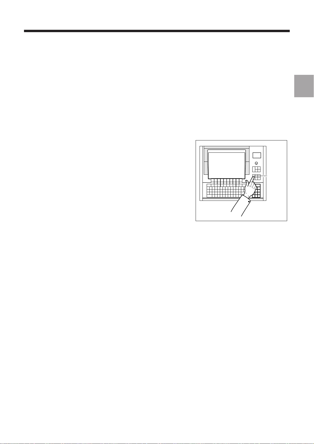
The actions required are presented as follows:
Reset the system. ☞
The keys to be pressed are indicated on the right. They can have two forms:
Square keys: correspond to keys on the operator panel.
UTIL
Rectangular keys: correspond to softkeys located in the block at the bottom of the screen and activated
by function keys (F2-F11) located under the screen.
Y
Dealers
The list of NUM dealers is given at the end of the manual.
Questionnaire
To help us improve the quality of our documentation, we ask you to return the questionnaire at the end of this manual.
14 en-938821/2
Page 17

Review
1 Review
1.1 System Overview 1 - 3
1.1.1 Overview of Modes 1 - 3
1.1.2 Defining a Programme 1 - 3
1.1.3 Preparing a Programme 1 - 4
1.2 Machine Overview 1 - 5
1.2.1 Review of Axis Definition and Direction 1 - 5
1.2.2 Machine Overview 1 - 6
1.2.3 Definition of Travels and Origins 1 - 7
1.2.4 Definition of Shifts 1 - 9
1.2.5 Definition of Tool Dimensions 1 - 14
1.2.6 Definition of Tool Wear Offsets 1 - 15
1
en-938821/2 1 - 1
Page 18

1 - 2 en-938821/2
Page 19
Review
MODE
This chapter does not aim to reflect the way an operator actually uses his machine. Rather, it attempts to explain certain
basic notions which will be referred to in this manual.
For example, in paragraph 1.2.4 (definition of shifts), the aim is not to impose a method of measuring shifts, but simply
to provide a definition of shifts and the corresponding zero points.
1.1 System Overview
1.1.1 Overview of Modes
The operator uses the numerical control (NC) in various operating modes
accessible from the operator panel.
Each mode corresponds to a particular use of the numerical control
(continuous machining, programme loading, tool setting, etc.).
1
1.1.2 Defining a Programme
A programme is a sequence of instructions written in a programming language specific to the numerical control (the
most widely used is ISO code: International Standards Organization).
The numerical control interprets the programme to control actions on a machine-tool.
The most widespread storage media for programmes are punched tape and diskettes.
en-938821/2 1 - 3
Page 20
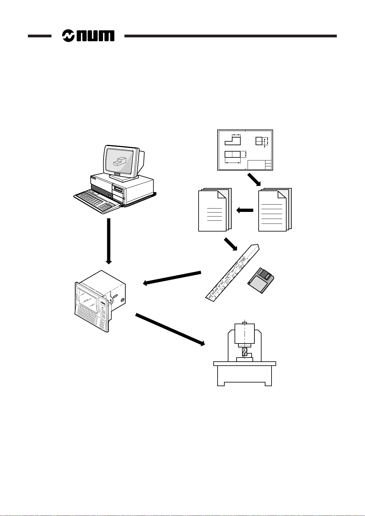
1.1.3 Preparing a Programme
A part programme can be created by traditional programming or using a CAD/CAM system.
CAD/CAM
Part
Programme
% 1
N10
N20
N30
Machining
instructions
1 - 4 en-938821/2
Page 21
1.2 Machine Overview
Z
C
B
A
X
0
Y
X
Y
Z
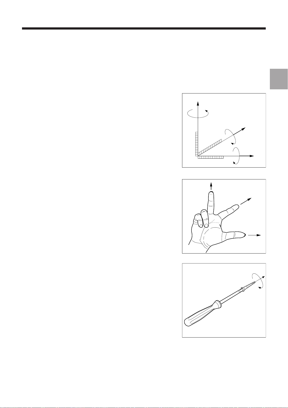
1.2.1 Review of Axis Definition and Direction
A coordinate system is used to identify the positions and movements of an
object with respect to an origin or zero point.
A rectangular cartesian coordinate system is a right-handed three-axis
system of three linear axes, X, Y and Z, with which are associated three
rotary axes, A, B and C.
Review
1
The direction of axes X, Y and Z is easily remembered by the right-hand
rule.
The positive direction of rotation of a rotary axis corresponds to the
direction of screwing of a right-hand screw on the associated axis.
en-938821/2 1 - 5
Page 22
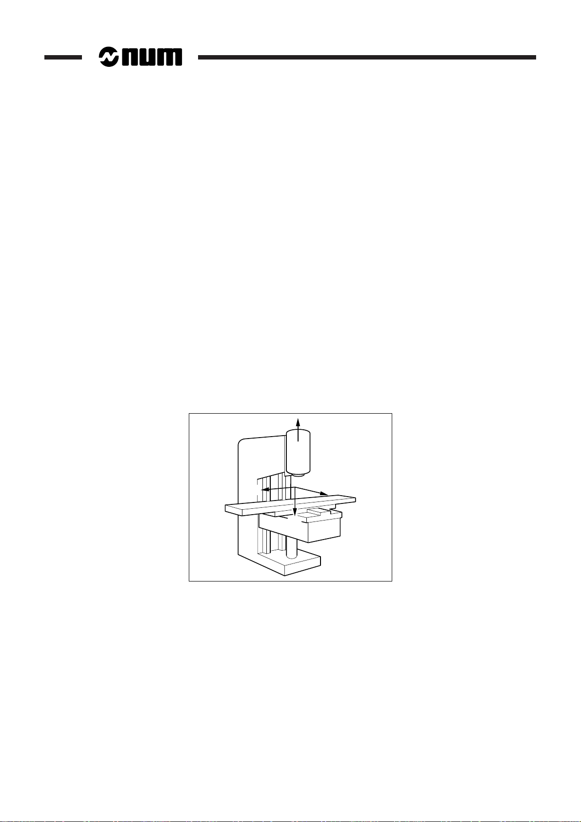
1.2.2 Machine Overview
The manufacturer defines the coordinate system associated with the machine in accordance with standard ISO 841
(or NF Z68-020).
The X, Y and Z axes, parallel to the machine slideways, form a right-handed rectangular cartesian coordinate system.
The coordinate system measures tool movements with respect to the part to be machined, assumed fixed.
REMARK When it is the part that moves, it may be more convenient to identify its
movements. In this case, axes X’, Y’ and Z’, pointing in opposite directions from
axes X, Y and Z, are used.
The direction of the axis of a machine depends on the type of machine and the layout of its components.
For a milling machine:
- the Z axis is the axis of the main spindle when this axis is parallel to one of the slideways,
- positive movement along the Z axis increases the distance between the part and tool,
- the X axis is perpendicular to the Z axis and corresponds to the largest excursion,
- the Y axis is perpendicular to the X and Z axes.
Rotary axes A, B and C define rotations around axes parallel to X, Y and Z.
Secondary linear axes U, V and W may or may not be parallel to primary axes X, Y and Z.
For more details, refer to the above-mentioned standard.
+Z
+X'
+Y'
+W'
1 - 6 en-938821/2
Page 23
1.2.3 Definition of Travels and Origins
Review
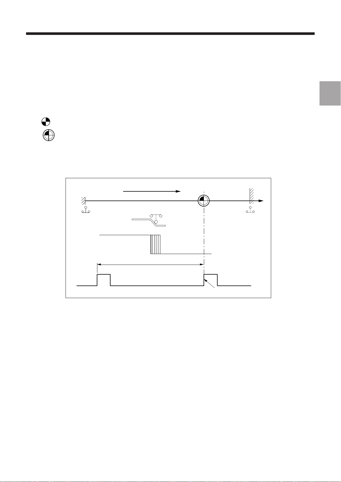
The NC processor computes all movements with respect to the measurement origin or zero point of the machine.
When the system is turned on, it does not know the measurement origin. The mechanical travel on each machine axis
is limited by maximum and minimum limit switches.
OM :
Om :
The homing procedure is completed for each of the axes when:
- the origin limit switch is actuated in the direction of movement specified by the m/c manufacturer (MOS direction),
- the encoder which measures axis movement outputs its marker pulse.
The system establishes the measurement origin (OM) via a homing procedure (MOS).
The home switch is set in a specific physical location: the machine zero point (Om) may or may not be the
same as the measurement origin (OM).
MOS direction
Om
Min. limit
switch
Contact closed Contact open
Max. limit
switch
1
One encoder revolution
Encoder marker pulse
en-938821/2 1 - 7
Page 24
When homing (MOS) is completed, the system applies the shift defined by the manufacturer to each of the axes to
establish the measurement origin (OM).
Measurement origin shift (Om/OM) = ORPOM
The useful travel on each axis is limited by software limits whose values are defined by the manufacturer.
Z
Mechanical travel
on X
travel
Useful
on X
ORPOM Z
Om
Volume accessible
during origin
setting
on Z
Useful travel
Mechanical travel
on Z
X
ORPOM X
Origin switch
+ encoder
zero pulse
OM
Useful travel
on Y
Mechanical travel
(limit switches) on Y
ORPOM Y
Y
1 - 8 en-938821/2
Page 25
1.2.4 Definition of Shifts
Review
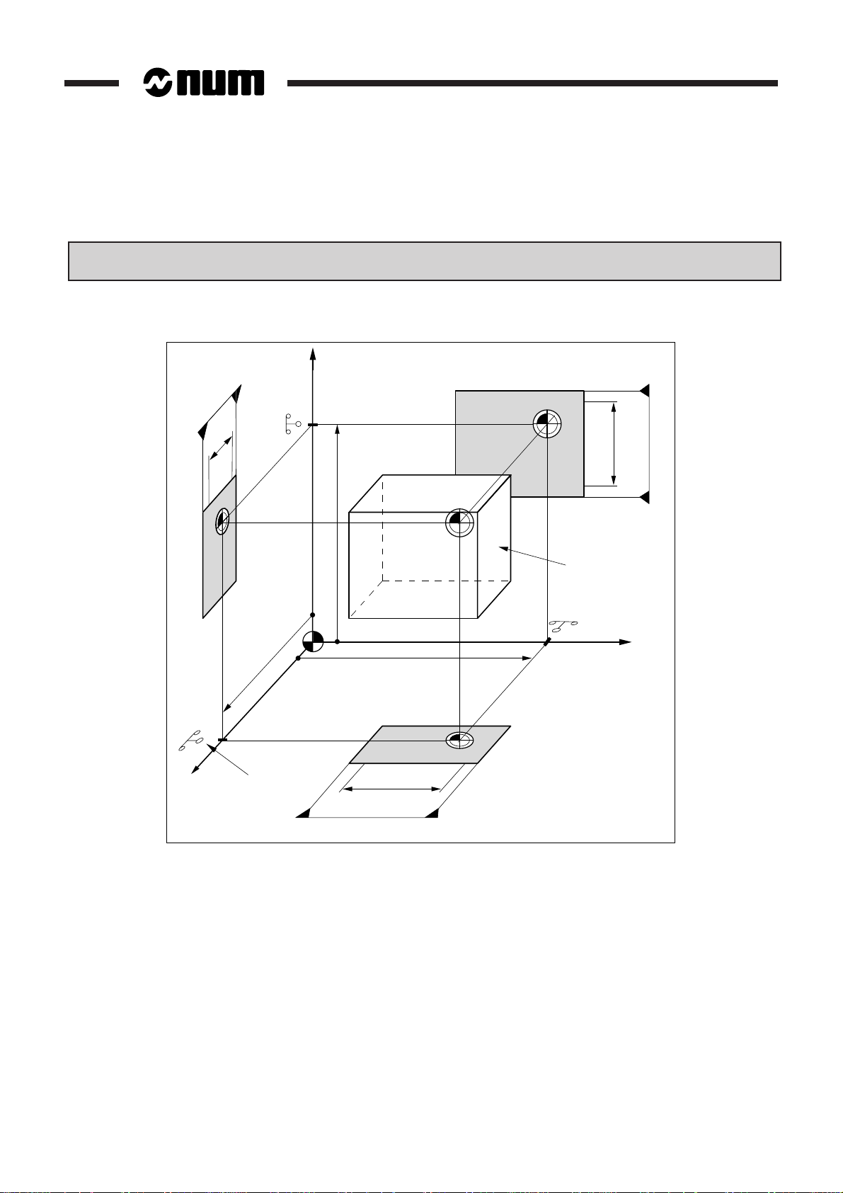
To write a part programme, the programmer chooses a programme origin.
The programme origin is generally a starting point for dimensional measurements on the part drawing.
OP :
Op :
The operator sets the programme origin (OP) as shown below:
He sets (for each axis) a known, accessible point on the part, called the part origin (Op). This may be the
same point as the programme origin.
Part datum shift (Op/OM) = DAT1
It is possible to set the DAT1 and DAT2 values from the part programme.
Programme datum shift (OP/Op) = DAT2
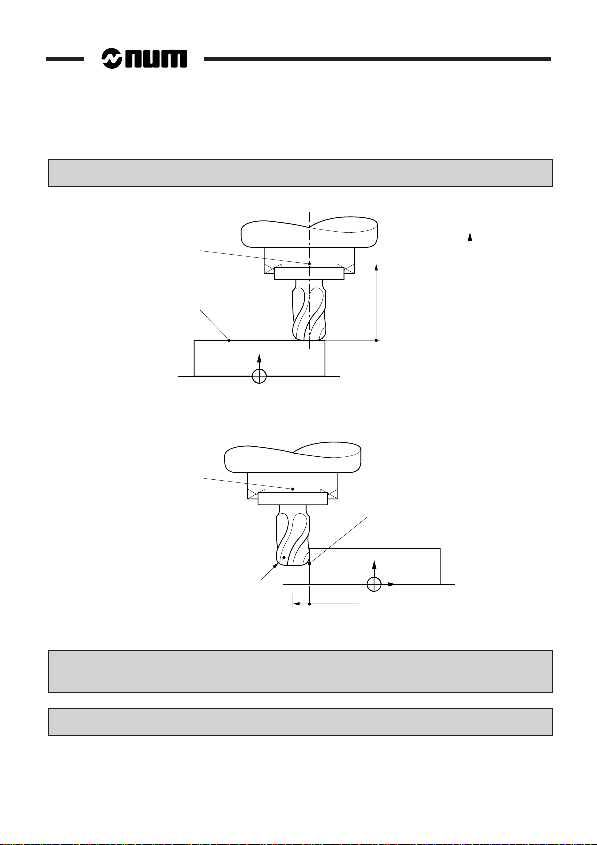
Shifts on the Z axis
Z
Spindle reference
Spindle axis
Setting
equipment
Z
Op
OM
Z DAT1
1
Part
OP
Z DAT2
X
en-938821/2 1 - 9
Page 26
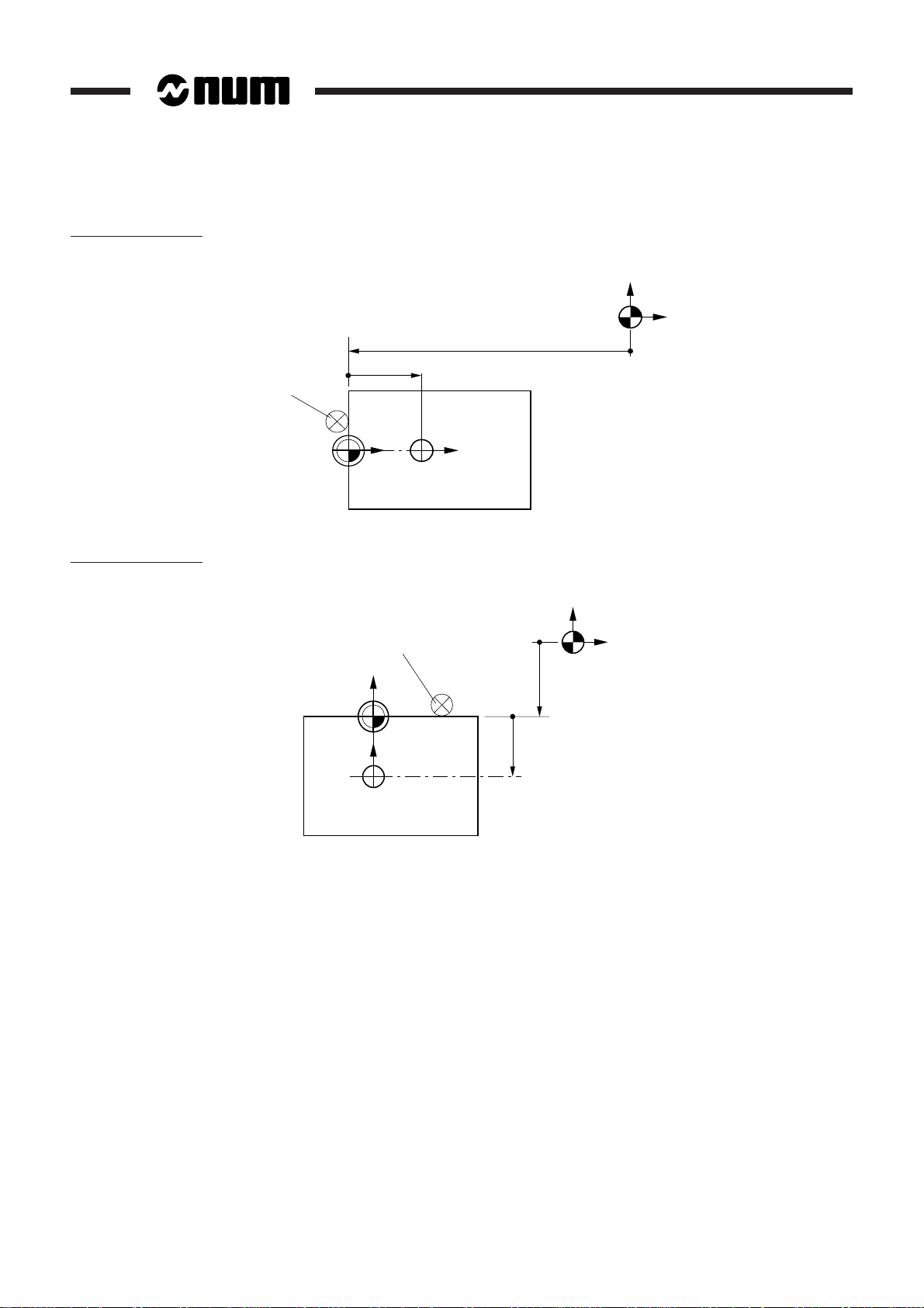
Shifts on the X axis
Y
X
Shifts on the Y axis
Locator
Op
X DAT2
XX
OP
Part
Locator
Y
Op
Y
OP
X DAT1
OM
Y
X
OM
Y DAT1
Y DAT2
1 - 10 en-938821/2
Part
Page 27
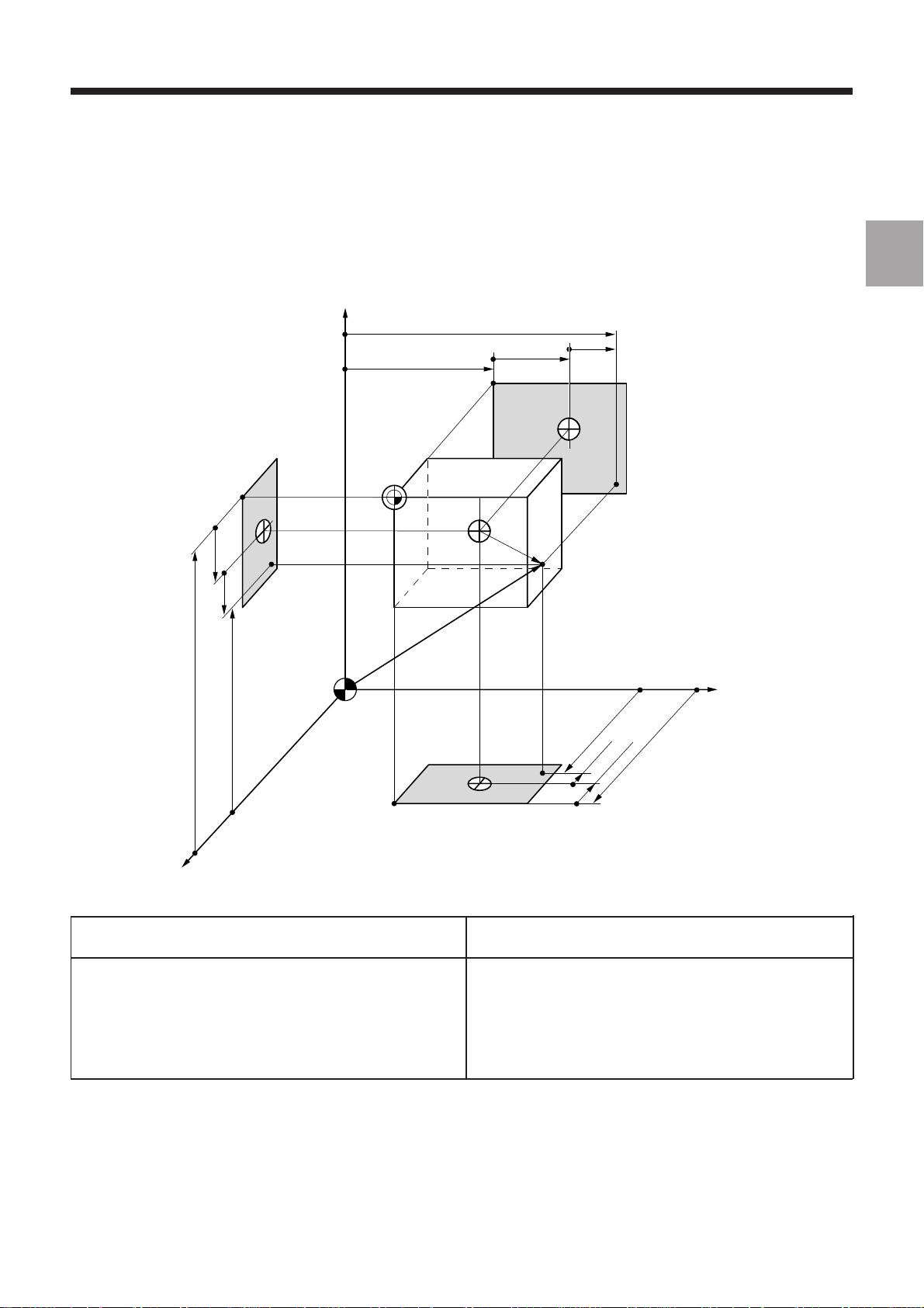
Review
The coordinates of any point (A) defined with respect to the programme origin (OP) are converted by the CNC into
coordinates with respect to the measurement origin (OM):
1
Z DAT2
Z DAT1
Z
Y DAT1
Op
PA
Z
OM
MA
X
PA,
Z
OP
Y
MA
Y
Y DAT2
PA
A
Y
MA
X
X DAT1
PA
X
Y DAT2
X
Programme dimensions Measurement dimensions
(with respect to OP) (with respect to OM)
X
PA
Y
PA
Z
PA
The dimensions are algebraic values.
Programmed shifts can be added to the measurement dimensions.
XMA = XPA + X DAT1 + X DAT2
YMA = YPA + Y DAT1 + Y DAT2
ZMA = ZPA + Z DAT1 + Z DAT2
en-938821/2 1 - 11
Page 28
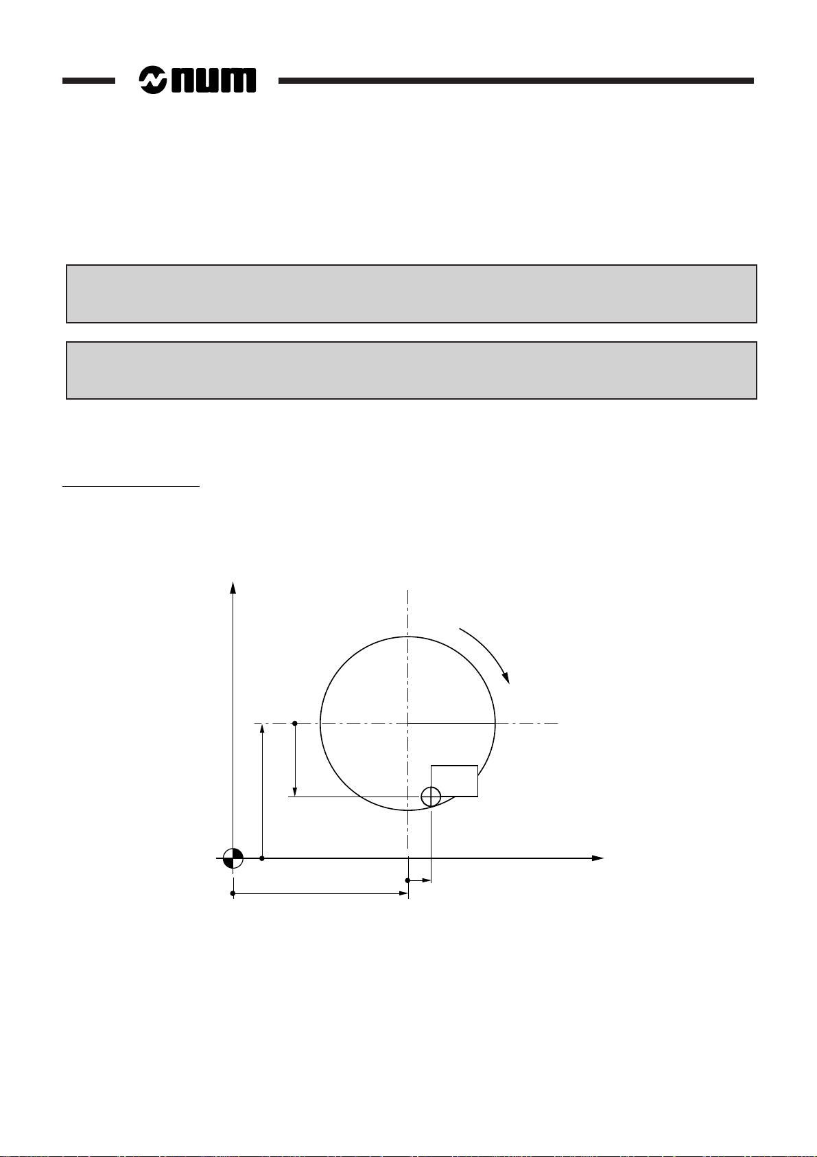
Special Case of Milling Machines Equipped with Rotary Tables
This concept of part origin only applies to the two axes affected by rotation.
The centre of rotation of the table (OC) has a particular role.
Offset of the centre of rotation (OC/OM) = DAT1
(axes affected by rotation)
Offcentring of the part (OP/OC) = DAT3
(axes affected by rotation)
REMARK For axes other than those affected by rotation, the previous definitions of DAT1
and DAT2 still apply.
Example: rotary axis B
Rotation is around an axis parallel to the Y axis. The axes affected by the rotation are Z and X.
X
B'
1 - 12 en-938821/2
X DAT1
OM
X DAT3
Z DAT1
OC
OP
Z
Z DAT3
Page 29
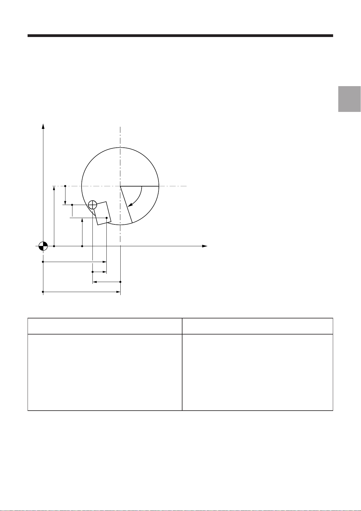
Review
The position of any point (A) defined with respect to the programme origin (OP) is converted by the CNC into
coordinates with respect to the measurement origin (OM):
X
B' = –B
OC
1
∆ X
PA
X
MA
X DAT1 (+ X DAT2)
X
OM
Z
MA
Z DAT1 (+ Z DAT2)
Programme coordinates Measurement coordinates
(with respect to OP) (with respect to OM)
OP
Z
PA
A
∆ Z
X
Y
B'
Z
PA
XMA = XPA + X DAT1 (+ X DAT2) + ∆X
with
∆X = X DAT3 x cos B - Z DAT3 x sin B
PA
YMA = YPA + Y DAT1 + Y DAT2
Z
PA
ZMA = ZPA + Z DAT1 (+ Z DAT2) + ∆Z
with
∆Z = Z DAT3 x cos B + X DAT3 x sin B
en-938821/2 1 - 13
Page 30
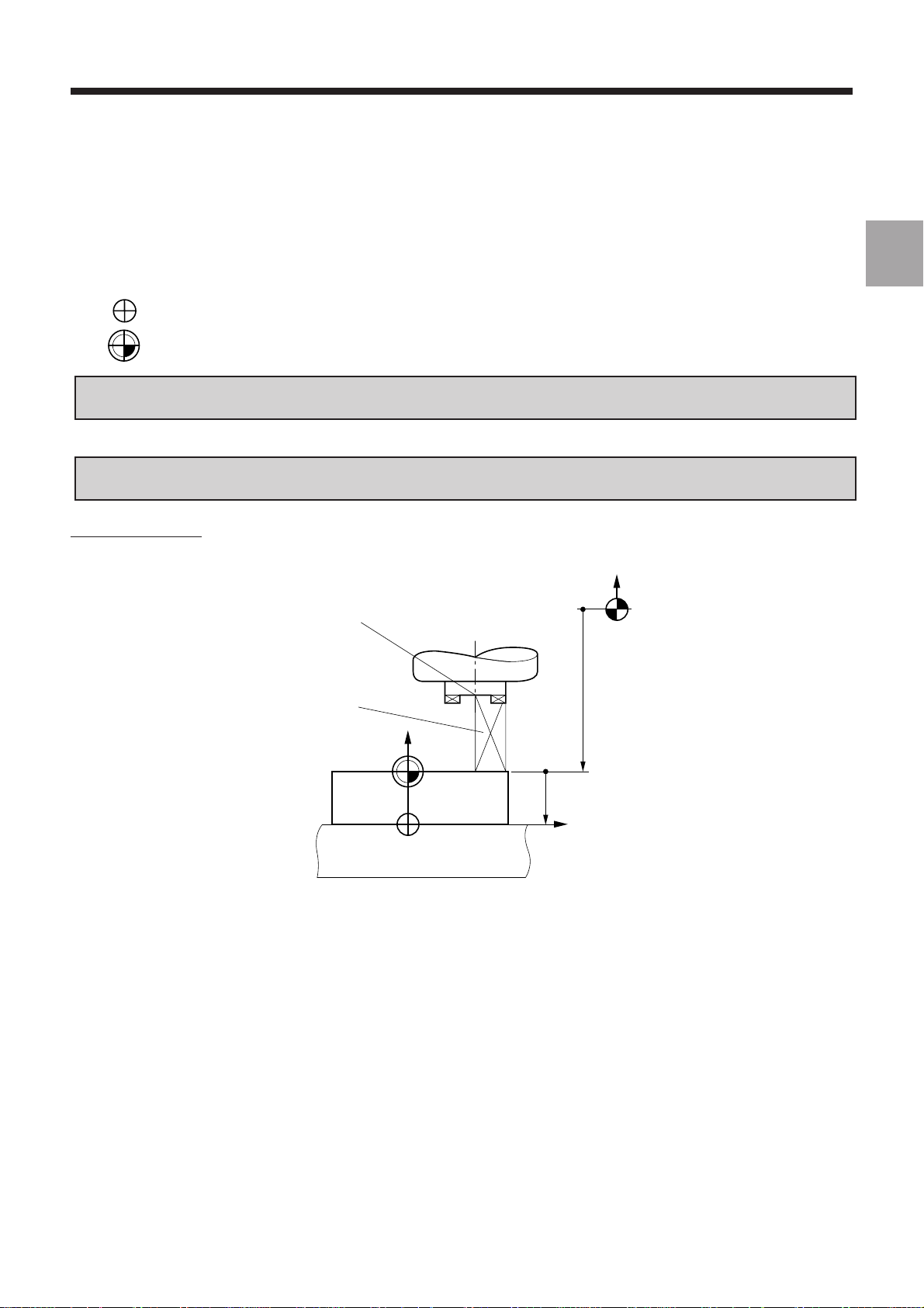
1.2.5 Definition of Tool Dimensions
Tool dimension = distance from tool cutting edge to spindle reference point
Spindle
reference
Part/tool
contact surface
Spindle
reference
Part
Cutter tip
radius (@)
Length (L)
Tool direction
Z
OP
Part/tool
contact surface
Part
Z
X/Y
1 - 14 en-938821/2
Radius (R)
Tool radius = R
Tool length = L
Cutter tip radius = @
OP
Page 31

1.2.6 Definition of Tool Wear Offsets
Review
At any time (even during machining), the operator can enter tool wear offsets when he observes a difference between
the expected and the actual results on a part.
The offsets (positive or negative) compensate for slight dimensional variations of the tool or part (wear, expansion).
Tool radius wear offset = DR
Tool length wear offset = DL
H
C
C + ∆C
H + ∆H
1
TOOL
DR = -∆C
-∆C
DR =
machining on both sides
2
DL = -∆H
for
The system takes into account the corrected tool dimensions:
Corrected radius = R + DR
Corrected length = L + DL
L + DL
R + DR
en-938821/2 1 - 15
Page 32

1 - 16 en-938821/2
Page 33

Product Presentation
2 Product Presentation
2.1 Environment 2 - 3
2.1.1 NUM 1060 Series I or NUM 1060 Series II 2 - 3
2.1.2 NUM 1020, 1040 and 1050 2 - 4
2.1.2.1 NUM 1020, 1040 and 1050 with CNC Panel
or Compact Panel 2 - 4
2.1.2.2 NUM 1020, 1040 and 1050 with FTP40
PC Panel 2 - 5
2.2 Switching on/off 2 - 6
2.2.1 Switching on 2 - 6
2.2.2 Restart Following an Emergency Stop 2 - 6
2.3 System Identification 2 - 7
2.3.1 Access to System Customisation
Attributes 2 - 7
2.3.2 System Customization Information Grid 2 - 17
2
en-938821/2 2 - 1
Page 34

2 - 2 en-938821/2
Page 35

Product Presentation
2.1 Environment
2.1.1 NUM 1060 Series I or NUM 1060 Series II
The following diagram illustrates the links between the CNC, the machine and the peripherals for NUM 1060 Series I
and NUM 1060 Series II systems with CNC panel or LCD panel or compact panel.
2
Panel
or
or
NUM 1060 Series I
or Series II CNC
or
Compact panel
Optional keyboard
SERIAL LINES
∗
INDUSTRIAL NETWORKS
• UNI-TELWAY
• MAP
• MAPWAY
Machine panel
Movement
sensor
MACHINE
Motor
Sensors
Actuators
Axes
Additional
handwheels
Servo-drive
External
interrupts
(measurement
probes)
PC or PS
Diskette drive
Printer
PERIPHERALS
∗ The compact panel is incompatible with the machine panel. An optional keyboard can be connected to the compact
panel.
en-938821/2 2 - 3
Page 36

2.1.2 NUM 1020, 1040 and 1050
2.1.2.1 NUM 1020, 1040 and 1050 with CNC Panel or Compact Panel
The following diagram illustrates the links between the CNC, the machine and the peripherals for a NUM 1020, 1040
or 1050 system with CNC panel or LCD panel or compact panel.
INDUSTRIAL NETWORKS
• UNI-TELWAY
• FIPWAY
Motor
External
interrupts
(measurement
probes)
Actuators
Sensors
Movement
sensor
Diskette
drive
PERIPHERALS
Axes
PC or PS
Printer
Panel
Serial line
or
50-key LCD panel
MACHINE
Additional
handwheels
Servo-drive
Compact panel
Optional keyboard
NUM 1020, 1040
or 1050 CNC
∗
∗ The compact panel is incompatible with the machine panel. An optional keyboard can be connected to the compact
panel.
2 - 4 en-938821/2
Page 37

Product Presentation
2.1.2.2 NUM 1020, 1040 and 1050 with FTP40 PC Panel
The following diagram illustrates the links between the CNC, the machine and the peripherals for a NUM 1020, 1040
or 1050 system with FTP40 PC panel.
2
Motor
External
interrupts
(measurement
probes)
Actuators
Sensors
Movement
sensor
INDUSTRIAL NETWORKS
• UNI-TELWAY
• FIPWAY
FTP40 PC panel
and keyboard
Serial line
Axes
MACHINE
NUM 1020, 1040
or 1050 CNC
Additional
handwheels
Servo-drive
en-938821/2 2 - 5
Page 38

2.2 Switching on/off
2.2.1 Switching on
Switch on the machine using the procedure defined by the OEM
Example of equipment power up sequence:
- general switching on (the CNC and the peripherals),
- switching on the power systems (with conditions related to the CNC).
When the CNC is switched on, a status window displays the following type of information:
12345
HOME
FREE M02 CN1
1 - Increment indicator: "FREE" is the default setting (another
increment can be selected by the PLC)
2 - "HOME" indicator: the measurement origin settings still to be
performed on the declared axes
3 - "M02" indicator: normal status of the system when not machining
(the "RESET" indicator is displayed if there is no PLC programme
or the PLC is faulty)
4 - "CN1" indicator: in single-panel configuration (single or multiple
CNC), the first CNC is the default CNC
5 - "OVER" and "CAPS" indicators: text editor is set to overtype
mode and upper case letters when the system is switched on
If one of these indicators is missing, a fault may be present on the system.
Notes
If the power to the CNC is switched off and back on, all the machining parameters (shifts, tool offsets, etc.) remain
stored; only the measurement origin is lost.
Incidents
Any message displayed when the CNC is switched on (See chapter 7) is linked to a system fault.
OVER
CAPS
2.2.2 Restart Following an Emergency Stop
An emergency stop automatically switches off the power to the machine actuators. The CNC remains energised and
retains all the machining data including movement commands.
Reset all the current movement commands. ☞
Restart the machine using the procedure defined by the OEM.
2 - 6 en-938821/2
Page 39

Product Presentation
2.3 System Identification
2.3.1 Access to System Customisation Attributes
The user can consult the pages indicating the customisation attributes which have been set for his system.
Requirements
Basic softkeys (See 3.1.4.2).
Actions
Select the "CNC COMMUNICATION DISPLAY" menu. ☞
Display of the "CNC COMMUNICATION DISPLAY" menu (See 4.10).
Select the first system identification page (after themenu). ☞
Display of the "AFFAIR AND SOFTWARE VERSIONS" page, e.g.:
AFFAIR AND SOFTWARE VERSIONS
1
JOB REFERENCE : XXXXXX 00
CNC SOFTWARE # : 202606G1
2
2
PLC
I / O
*
8
1 - Job reference
2 - Software version and index
en-938821/2 2 - 7
Page 40

Select the next page. ☞
Display of "OPTIONS" page, e.g.:
. . / . .
DAT
0 1 2 3 4 5 6 7 8 9 10 11 12
X X 0
X x 1
X 2
X X 3
O
4
5
P
6
7
T
8
9
I
13 14 15 16 17 18 19 20 21 22 23 24 25
0
O
1
2
N
3
4
S
5
6
7
8
9
1 - Tens
2 - Units
3 - "X" indicates that the corresponding function is available
1
2
3
2 - 8 en-938821/2
Page 41

The table below lists the functions available.
Number Function
0 3D display
1 Double windowing graphics
2 Hard copy
3 Additional language for CNC software
4 Program display/edit for NUM Tplus
5 Program load/unload and graphic simulation for NUM Tplus
10 Axis calibration: access to Utility 2, axis Calibration
access to Utility 20, Interaxis Calibration
11 Dynamic operators
12 Synchronised and duplicated axes
13 Multigroup function
14 Inclined axes
15 Inclined plane
16 N/M auto function
17 RTCP (Rotation around Tool Centre Point)
18 High speed machining of precision contours
19 Dynamic operators in C
20 Rigid tapping
21 Slaving of axes to spindle (G31, G33, G38)
22 Integrated spindle synchro
30 3D tool radius offset
31 Extension of number of corrections to 255
32 Tool wear offset control by the PLC
33 5-axis tool dimension
40 PROCAM interpreter
41 Accuracy setting
42 PGP (Profile geometry programming)
43 Resident macros: Access to Utility 3
44 Scaling factor
45 Programmable angular shift
46 Structured programming
47 Transfer of active parametric values into the part programme
48 Radial axis (boring function)
49 Irregular pockets and islands
50 Cartesian, polar and cylindrical conversion
51 Spline curve
52 Smooth polynomial interpolation
53 Creation of profile storage table
55 2D circular interpolation
Product Presentation
2
en-938821/2 2 - 9
Page 42

Number Function
60 Turning functions
61 Milling functions
62 Mixed machine functions
63 Selection of 1020 (=0) or 1040 (=1)
64 NUM 1040 GP: four axis groups (=1)
65 NUM Tplus (=1)
70 Emergency retraction
71 On-the-fly measurement acquisition
72 Backtrack along path
80 Coprocessor interchange protocol
81 UNI-TELWAY
82 Telemaintenance
83 DNC1
84 3-layer network
85 7-layer network
86 High speed console line
87 FIPWAY
90 PLC programming in C
91 Gear grinding
92 Automatic gear alignment
93 Access to utility 6 (=1)
100 Application development software tool
101 NUMAFORM
103 PROCAM TURN or MILL
104 PROCAM MULTITURN
105 PROCAM MX (mixed machine)
106 PROCAM Grinding
107 Rigid tapping (on diskette)
108 Spindle synchronisation (on diskette)
109 RTCP (Rotation around Tool Centre Point) on diskette
127 Servo-control simulation
200 Milling package for DIDACNUM turning
201 Turning package for DIDACNUM milling
202 WOODplus
203 PCToolKit
210 MMITool interpreter
211 Package of basic options for NUM subsidiaries
2 - 10 en-938821/2
Page 43

Product Presentation
Select the next page. ☞
Display of the "AXES NUMBER" page (the numbers displayed on this page are set during the customization
procedure), e.g.:
. . / . .
DAT
AXES NUMBER
1
NUMBER OF CNC OR PLC AXES : 7
NUMBER OF SPINDLES : 2
NUMBER OF INTERPOLATED AXES : 5
2
3
NUMBER OF PLC ONLY AXES : 2
4
1 - Total number of axes authorized on the system (CNC axes +
PLC axes)
2 - Total number of spindles authorized
3 - Number of simultaneous interpolated axes
4 - Number of axes exclusively controlled by the PLC
2
en-938821/2 2 - 11
Page 44

Select the next page. ☞
Display of the "MEMORY SIZES" page (these sizes are set during the customization procedure), e.g.:
. . / . .
DAT
MEMORY SIZES
1
PART PROGRAMME STORAGE : 1024
PLC PROGRAMME STORAGE : 256
MMI PROGRAMME STORAGE : 800
1 - RAM size assigned to part programmes
2 - RAM size assigned to the PLC
3 - RAM size assigned to MMITool
(man/machine interface customisation tool)
2
3
2 - 12 en-938821/2
Page 45

Product Presentation
Select the next page. ☞
Display of the "HISTORY" page, e.g.:
HISTORY
1
FACTORY OUT :
26 / 2 / 92 15:20:65 CABE-EF
2
LAST MODIFIED ON :
8 / 6 / 94 10:37:23 D2R2
1 - Date, time and identification of the first person to customize the
system
2 - Date, time and identification of the last user to customize the
system using utility 12
. . / . .
DAT
2
en-938821/2 2 - 13
Page 46

Select the next page. ☞
Display of the "SYSTEM BUS HARDWARE CONFIGURATION" page for instance:
SYSTEM BUS HARDWARE CONFIGURATION
Address Designation File number Vers. Ident.
Unknown card 000 000 000 8 $0007F8
0 4M V2 graphic processor 204 202 778 0 $005340
1 1M PLC 204 201 935 0 $004B00
2 V2 1,7/2M memory board 204 202 301 0 $008D80
3 4 V1 14b encoder axes 204 201 982 0 $000E00
4
5
6
7
8
9
10
11
12
13
.../...
1 2 3 4 5
. . / . .
DAT
1 - Card address on the system bus (the addresses are numbered
from 0 to 13 starting from the right end of the rack)
2 - Card description
3 - Part number of each card
4 - Card functionality index (decimal conversion of the last character
of the identifier. For instance, if the last character is D, the
functionality index is 13)
5 - Electronic identifier of each card (this number is used to ensure
card interchangeability).
Each line of the "SYSTEM BUS HARDWARE CONFIGURATION" page gives information on a card installed on the
system bus.
The first line corresponds to the system bus backplane card.
Blank lines correspond to empty card slots.
If the card identifier is unknown, the message "card unknown" is displayed in the "Description" column.
2 - 14 en-938821/2
Page 47

Product Presentation
Select the next page. ☞
Display of the "PLC BUS HARDWARE CONFIGURATION (RACK 0)" page, for instance:
PLC BUS HARDWARE CONFIGURATION (RACK 0)
Address Designation File number Vers. Ident.
0 Main serial bus 204 201 857 0 $000000
0 130W power supply with optic F. 204 201 950 0 $000000
1
2
3
4
5 32 inputs board 204 201 926 0 $000A00
6 32 relayed outputs board 204 201 746 0 $000100
7
8
9
10
11
12
13
1 2 3 4 5
. . / . .
DAT
2
1 - Address on the serial bus:
- address 0 corresponds to the serial bus and the fibre-optic
interface on the power supply card
- addresses 1 to 4 are reserved for the machine panels
- addresses 5 to 12 are reserved for the input/output cards
2 - Card description
3 - Part number of each card
4 - Card functionality index (decimal conversion of the last character
of the identifier. For instance, if the last character is D, the
functionality index is 13)
5 - Electronic identifier of each card (this number is used to ensure
card interchangeability)
Each line of the "PLC BUS HARDWARE CONFIGURATION (RACK 0)" page gives information on a module installed
on the serial bus.
Blank lines correspond to empty slots.
When the system includes extension racks, the sign ".../..." is displayed in the bottom right-hand corner of the page.
en-938821/2 2 - 15
Page 48

To display the contents of the extension racks:
Select the next page as many times as necessary. ☞
. . / . .
DAT
The "PLC BUS HARDWARE CONFIGURATION (RACK X)" page is displayed.
It contains the same type of information as the "PLC BUS HARDWARE CONFIGURATION (RACK 0)" page; the input/
output cards occupy slots 1 and 2 (two-card extension racks) or 1 to 12 (12-card extension racks).
Notes
If no PLC is present, the message "PLC MISSING" is displayed in the "PLC BUS HARDWARE CONFIGURATION"
page.
If a CL7 controller card (link with a TSX series 7 PLC) is present, no PLC bus configuration page is displayed.
Exit from the procedure
Select a display page.
2 - 16 en-938821/2
Page 49

Product Presentation
2.3.2 System Customization Information Grid
The system customization parameters can only be consulted when the system is operational.
It is recommended to write this information down for communication to the OEM or NUM customer support in case of
a failure preventing consultation.
MACHINE IDENTIFICATION
Machine No.: Shop:
CUSTOMISATION
2
Job reference:
Options present:
0 1 2 3 4 5 6 7 8 9 10 11 12
0
1
2
3
4
5
6
7
8
9
Total number of axes:
Number of interpolated axes:
Part programme RAM size:
CNC software #:
Number of measured splindles:
Number of machine proc. axes:
Machine processor RAM size:
Date factory out:
Date last modified on:
HISTORY
Identification:
Identification:
en-938821/2 2 - 17
Page 50

The following table can be reproduced as many times as there are "BUS XXX HARDWARE CONFIGURATION" pages.
HARDWARE CONFIGURATION OF BUS ____________
Address Description Part Number Index Identifier
0
1
2
3
4
5
6
7
8
9
10
11
12
13
2 - 18 en-938821/2
Page 51

Operator Panel Description
3 Operator Panel Description
3.1 NUM Panels and Sub-Assemblies 3 - 3
3.1.1 NUM Panels 3 - 3
3.1.1.1 QWERTY Panel and CRT 3 - 3
3.1.1.2 50-Key Panels with CRT 3 - 4
3.1.1.3 50-Key Panel with LCD 3 - 4
3.1.1.4 Compact Panel 3 - 5
3.1.2 Display Screen 3 - 6
3.1.3 Status Window 3 - 7
3.1.4 Softkeys 3 - 8
3.1.4.1 Root Softkey Bar (Compact Panel) 3 - 8
3.1.4.2 Basic Softkeys 3 - 8
3.1.4.3 Mode Softkeys 3 - 8
3.1.4.4 JOG Softkeys 3 - 9
3.1.4.5 Tool Softkeys 3 - 10
3.1.4.6 Character Softkeys of the Compact Panel 3 - 10
3.1.5 Modal Data Window 3 - 11
3.2 Interactions Between Mode Selections and Display Pages 3 - 12
3.2.1 Neutral Mode 3 - 12
3.2.2 Interactions between Modes 3 - 12
3.2.3 Interactions between Modes and
Display Pages 3 - 12
3.3 Available Controls and Indicators 3 - 13
3.3.1 Keyboard Keys 3 - 13
3.3.1.1 Special Features of the 50-Key
Panel Keyboard 3 - 13
3.3.1.2 Special Features of the Compact
Panel Keyboard 3 - 13
3.3.1.3 Special Keyboard Keys 3 - 14
3.3.1.4 Special Control keys 3 - 15
3.3.1.5 Mode Selection Keys 3 - 16
3.3.1.6 Reset Key 3 - 16
3.3.1.7 Machine Panel Function Keys on the
Compact Panel 3 - 16
3.3.2 Softkeys 3 - 17
3.3.2.1 Root Softkeys (Compact Panel) 3 - 17
3.3.2.2 Basic Softkey Functions 3 - 17
3.3.2.3 Mode Softkey Functions 3 - 18
3.3.2.4 JOG Softkey Functions 3 - 19
3.3.2.5 Tool Softkey Functions 3 - 19
3.4 Special Keyboard Operations 3 - 20
3.4.1 Hardcopy 3 - 20
3.4.1.1 Hardcopy on Printer 3 - 20
3.4.1.2 Hardcopy in File 3 - 21
3.4.2 Keyboard Sound 3 - 22
3.4.3 Switching between Operator Panels 3 - 22
3.4.4 Switching between CNCs 3 - 23
3.5 Use of a 102/105-Key Keyboard with the Compact Panel 3 - 24
3
en-938821/2 3 - 1
Page 52

3 - 2 en-938821/2
Page 53

3.1 NUM Panel and Sub-Assemblies
3.1.1 NUM Panels
3.1.1.1 QWERTY Panel and CRT
Operator Panel Description
5
4
3
6
3
2 4
1
3
7
8
MODE
JOGTOOL
M01
2
9
F10
F9
{
[}]
";:
`
,<.>/
F11 F12
`
?
ALL
CAPS
J
F8F7F6F5F4
KL
MNBVCXZSHIFT SPACE
F1
!1@2#3$4%
ESC Q W E R T Y U I O P
1
CTRL A D F G H
F3F2
5^6&7*8(9)0_-+=+
S
x off
/
HELP
line
line
DEL
INS
char
char
home Pg Up
VALID
Pg Dnend
10
1 - QWERTY alphanumeric keyboard
2 - Key to access previous softkeys
3 - Function keys
4 - Colour CRT
5 - Brightness control
6 - Context selection keys
7 - Reset key
8 - Mode selection keys
9 - Key to access next "Mode" softkey
10 - Cursor control keys
en-938821/2 3 - 3
Page 54

3.1.1.2 50-Key Panels with CRT
4
1 2 3
3
N GHF
A
2
YBV(J)T
C
PDQ
SHIFT
1
F10F9F8F7F6F5F4F3F2F1 F11 F12
HELP
R
CTRL
MODE
'
M
_
?
S
I;U:X
{
x off
L
TOOL
]
E
SPACE
,
+K[WZ
JOG
}
"
\ ~0
7&8 9
S
4 5 6
!
∗0= /
INS/
OVER
ENTER
line
DEL
char
3#2@1
home
PgUp
end
PgDn
5
6
7
8
9
10
1 - Key to access previous softkeys
2 - Function keys
3 - Key to access next "Mode" softkeys
4 - 9" Monochrome or 10" colour screen
5 - Context selection keys
6 - RESET key
7 - Compact alphanumeric keyboard
8 - Brightness control
9 - Mode selection keys
10 - Cursor control keys
3.1.1.3 50-Key Panel with LCD
This assembly includes a 50-key panel and a separate LCD. It has the same functions as the 50-key panel with CRT
(see 3.1.1.2).
1 2 3
F10F9F8F7F6F5F4F3F2F1 F12F11
N GHF
YBV(J)T
SHIFT
HELP
A
C
PDQ
CTRL
MODE
_
I;U:X
{
}
"
E
L
R
SPACE
TOOL
'
M
?
S
x off
,
]
+K[WZ
JOG
7&8 9
S
4 5 6
!
∗0= /
INS/
OVER
ENTER
line
DEL
char
\ ~0
3#2@1
home
PgUp
end
PgDn
3 - 4 en-938821/2
Page 55

Operator Panel Description
3.1.1.4 Compact Panel
The compact panel is used for production and settings. It combines the functions of a CNC panel and a machine panel.
It can be used for ISO programming and maintenance by connecting a standard 102/105-key PC keyboard.
2
34
1
H
F
x
T-=
Z+!
C
Q.R
16
G%ME/
7N8S9
4X5Y6
1A2B3
DP0
a
F1 F2 F3 F4 F5 F6 F7 F8 F9 F10 F11 F12
15 14 13 12 11
1 - 9" monochrome or 10" colour CRT 10 - DIN connector for additional standard 102/
2 - Data entry keys 105-key PC keyboard (this connector can
3 - Special keys be moved to the rear of the panel; see 3.5)
4 - Programmable keys (two functions per 11 - Reset key
key: key alone and Shift + key) ∗ 12 - Lighted CYCLE key ∗
5 - Emergency stop switch 13 - Lighted FEED STOP key ∗
6 - Lighted on/off switch 14 - Special cursor control keys and Shift key
7 - Feed rate override potentiometer 15 - Cursor control keys
8 - Axis jogs ∗ 16 - Function keys
9 - Serial port
10
3
5
6
7
8
9
∗ These machine keys remain active when the screen saver is on (the other keys merely turn the screen back on).
en-938821/2 3 - 5
Page 56

3.1.2 Display Screen
1 - Status window
2 - Main window (20 lines of small characters)
3 - Modal data window
4 - Dialogue window (3 dialogue lines)
5 - Softkey bar
1
2
3
4
5
Certain screens do not have a dialogue window. In this case, 11 lines of large characters are displayed.
3 - 6 en-938821/2
Page 57

Operator Panel Description
3.1.3 Status Window
The status window shows the status of the CNC at any given time via indicators displayed in 17 fields.
When no indicators are required in a field, it is not displayed.
18234567
LOAD
TLCOMP
MDI
.1
17 916 15 14 13 11 10
/
NC ?? CYHLD
AXRCL
M01 INCYC CN1
MSGFDHLD
mm
12
N_POS
OVER
LCASE
1 - Current mode (See list of modes: 3.3.2.2)
2 - Entry of tool dimensions (TLCOMP), entry of tool wear offsets
(WEAR +) or cancellation of tool wear offsets (WEAR 0)
3 - Block skip (/) enabled
4 - Fault (NC ?? flashing) or MOS not performed (HOME flashing)
5 - Machining stop (CYHLD)
6 - Feed interruption (FDHLD)
7 - Message present (MSG)
8 - Overtype text mode (OVER) or insert mode (INSRT)
9 - Upper case letters (CAPS) or lower case letters (LCASE)
10 - Axis not in position (N_POS) or hardcopy in progress (HCOPY)
or hardcopy fault (HCDEF)
11 - Panel number (KBD1 or KBD2) in multi-panel configuration,
number of active CNC (between CN1 and CN4) in multi-CNC
configuration or system fault (PRSOV)
12 - Display unit: millimetres (mm) or inches (inch)
13 - End of part programme (M02), programmed stop (M00),
reset (momentary display of RESET) or current cycle (INCYC)
14 - Axis recall (AXRCL flashing) or manual override (INTER
flashing)
15 - Optional stop (M01) enabled
16 - Selected JOG increment (.001 to 10000, FREE or HANDWH)
17 - Standby mode
3
Special Case of the Compact Panel
The status window displayed on a compact panel is somewhat different from the standard status window:
- It includes a field indicating the name of the axis controlled by the jogs, followed by the group number in multigroup
systems
- It includes fields with indicators for the programmable function keys (lit if the function is active).
1
LOAD
TLCOMP
MDI
X1 FCT
/
NC?? CYHLD
100
AXRCL
M01 INCYC CN1
MSGFDHLD
mm
3
N POS
OVER
SFCT
1 2 3 4 5 6
1 2 3 4 5 6
2
1 - LEDs for the shifted programmable function keys
2 - LEDs for the programmable function keys
3 - Axis name followed by group number
en-938821/2 3 - 7
Page 58

3.1.4 Softkeys
The softkeys of the compact panel differ from those of the other CNC panels. Since the compact panel has fewer keys,
certain keys of the CNC panels are replaced by softkeys (see the sections "Special Case of the Compact Panel").
These softkeys are accessible in special softkey bars of the compact panel:
- The root softkey bar gives access to the Mode, Jog, Tool and Character softkeys
- The first Jog softkey bar is used to select the axis controlled by the jogs
- The two Mode softkey bars, the Tool softkey bar and the second Jog softkey bar (only Jog softkey bar on CNC
panels) are different
- The Character softkey bars allow entry of characters not available on the compact panel keyboard.
3.1.4.1 Root Softkey Bar (Compact Panel)
MODE
The Root softkey bar on the compact panel provides the functions accessible on other CNC panels by the
JOG
and
keys as well as giving access to the character keybars.
To display the Root softkeys, press the context key .
TOOL JOGMODE SYMBOL
To return to the basic softkeys, press again.
3.1.4.2 Basic Softkeys
TOOL
,
. . / . .
DAT
DIR. PROG. INFO. L / @ AXIS TOOLS BKGND
PLC
I / O
UTIL
These softkeys are displayed when none of the following softkeys have been selected:
- Mode softkeys,
- JOG softkeys,
- Tool softkeys.
To return to the basic softkeys, press the selection key of the softkey bar displayed (Mode, Jog or Tool) or, with the
QWERTY keyboard, press the key.
3.1.4.3 Mode Softkeys
Access the start of these softkeys by pressing
SINGLE MDI DRYRUN SEARCH EDIT TEST MANUAL HOMEAUTO
Access the following functions by pressing or
TL SET LOAD UNLOADSHIFTS
MODE
.
MODE
.
Once a mode has been selected, the basic softkeys are redisplayed.
REMARK The modes can be cancelled individually by PLC programming (see Automatic
Control Function Programming Manuals). In this case, the corresponding
softkeys are not displayed.
3 - 8 en-938821/2
Page 59

Special case of the Compact Panel: Mode Softkeys
Access the first Mode softkeys by pressing the
SINGLE MDI DRYRUN SEARCH EDIT TEST MANUAL HOMEAUTO
MODE
Operator Panel Description
key of the Root softkey bar.
Access the second Mode softkeys by pressing the key (F12) or the Next key
TL SET LOAD UNLOADSHIFTS
Return to the first Mode softkeys by pressing (F12) or the Next key
. . / . . .
. . / . . .
.
.
Return to the Root softkeys by pressing (F1).
3.1.4.4 JOG Softkeys
Access these softkeys by pressing
.1 1 10 100 1000 10000 FREEHANDW .01.001
JOG
.
REMARK The increments can be cancelled individually by PLC programming (see Automatic
Control Function Programming Manuals). In this case, the corresponding
softkeys are not displayed.
Special Case of the Compact Panel: Jog Softkeys
Access the first Jog softkeys by pressing the
Z A B C HANDWYX
Names of the axes declared in P9
JOG
key of the Root softkey bar.
3
The first Jog softkeys contain the names of the first axes (maximum 6) declared in machine parameter P9. They are
used to select the axis to be controlled by the jogs.
In multigroup systems, the axis name is followed by the group number declared in P9:
X
GR1
GR1XGR2ZGR2
GR1
Access the second Jog softkeys by pressing (F12) or the Next key
.1 1 10 100 1000 10000 FREE.01.001
Return to the first Jog softkeys by pressing (F12) or the Next key
HANDW
. . / . . .
. . / . . .
.
.
Z
Y
Return to the Root softkeys by pressing (F1).
en-938821/2 3 - 9
Page 60

3.1.4.5 Tool Softkeys
Access these softkeys by pressing
TOOL
.
TLCOMP
WEAR + L or X R or Z WEAR 0
Special Case of the Compact Panel: Tool Softkeys
Access the Tool softkeys by pressing the
TLCOMP
LR@
WEAR + L or X R or Z WEAR 0
TOOL
key of the Root softkey bar.
The tool softkeys contain the characters L, R and @.
Return to the Root softkeys by pressing (F1).
3.1.4.6 Character Softkeys of the Compact Panel
Use of these softkeys on the compact panel should be exceptional. It is preferable to connect a standard PC keyboard.
Access the first Character softkeys by pressing the
;|JKLOUV#W
SYMBOL
key of the Root softkey bar.
Access the second softkeys by pressing (F12).
()[]<>&:$?
Access the third softkeys by pressing (F12).
"
`'
\ ↑ _{}
|
~
The symbol Î represents a caret.
Return to the first softkeys by pressing (F12). Return to the Root softkeys by pressing (F1).
3 - 10 en-938821/2
Page 61

Operator Panel Description
3.1.5 Modal Data Window
The modal data window displays information concerning the programme being executed:
6
5
4
3
2
1
%20 . 0
N150
H6558 . 2
G40G2
G94G90
G83
M9M3
T12 D12
Sp: 600
S%: 75%
Fp: 1000
F%: 100
7
8
9
10
11
12
13
14
15
16
1 - Tool number
2 - Spindle rotation direction (M3 or M4), spindle off (M5) or
spindle indexing (M19)
3 - Current cycle (G31, G45, G81 to G89)
4 - Programming of movements in absolute (G90) or relative
(G91) dimensions
5 - Programmed interpolation function (G0 to G3)
6 - Current programme
7 - Current block
8 - Active subroutine
9 - Radius offset (G41 or G42) or radius offset cancel (G40)
10 - Feed rate in V/D (G93), in mm/min (G94) or mm/rev (G95)
11 - Programmed coolant (M7, M8 or M7M8) or coolant off (M9)
12 - Tool correction
13 - Programmed spindle speed
14 - Spindle speed override percentage set on the spindle speed
potentiometer
15 - Programmed feed rate
16 - Feed rate override percentage set on the feed rate
potentiometer
3
On certain screens, the modal data window may include different data. This is the case for simulated machining (see
4.6.2) and use of the PROFIL function (see 5.7.2).
en-938821/2 3 - 11
Page 62

3.2 Interactions Between Mode Selections and Display Pages
3.2.1 Neutral Mode
When the CNC is switched on, no mode is active and the "current mode" field of the status window is not displayed:
the CNC is in neutral mode.
The alphanumeric keyboard is inactivated.
3.2.2 Interactions between Modes
When a mode is selected from the Mode softkeys, its name is automatically displayed in the "current mode" field of
the status window (assuming that the selection is authorised by the machine processor).
Two modes cannot be active at the same time:
- when no cycle is in progress (indicator "M02" displayed in the status window), each time a mode is selected, it
replaces the previous selection,
- when a cycle is in progress (indicator "INCYC" displayed in the status window), each time a new mode is selected,
its name is displayed in the "standby mode" field.
When a mode is on standby, it is activated:
- at the end of a cycle for all modes except automatic mode,
- at the end of a block for automatic mode (or at the end of a cycle if the block being executed comprises a canned
machining cycle such as G31 or G81).
3.2.3 Interactions between Modes and Display Pages
When a display page is selected from the basic softkeys, this page is displayed in the main window.
Changing pages returns the CNC to neutral mode in the following cases:
- if the CNC is in edit or origin shift mode (SHIFTS)
- if the CNC is in loading or unloading mode but not in progress
When the system is in edit mode and a new mode (other than homing, loading and unloading) is selected, the "current
position" page is displayed.
Irrrespective of which mode is active, when the:
- edit mode is selected, the active programme is displayed,
- homing mode is selected, the SHIFTS page is displayed,
- loading mode is selected, the "FILE LOADING" menu is displayed,
- unloading mode is selected, the "FILE UNLOADING" menu is displayed unless the CNC is in graphic display mode.
3 - 12 en-938821/2
Page 63

Operator Panel Description
3.3 Available Controls and Indicators
3.3.1 Keyboard Keys
3.3.1.1 Special Features of the 50-Key Panel Keyboard
On the alphanumeric keyboard of the 50-key panel:
- the main character on the key can be accessed directly,
- the character in the top right-hand corner of the key is accessed by pressing the shift key together with the key,
- the character in the bottom right-hand corner of the key is accessed by pressing the control key together with the
key.
3
SHIFT
CTRL
+ key
+ key
S
x off
Accessed by
?
Main character accessed by key alone
Accessed by
Adaptation of the Procedures
The procedures described herein are based on the use of the QWERTY panel.
When using the 50-key panels, these procedures should be adapted by using the shift or control key combinations
where necessary.
Example
The following line of a procedure:
Confirm password removal. ☞
Y
Adapted as follows for use on the 50-key panel:
Confirm password removal. ☞
SHIFT
+
O
ENTER
M
Deleting the dialogue line
line
On 50-key panels, the dialogue line is deleted by the key combination
SHIFT
+
DEL
.
char
3.3.1.2 Special Features of the Compact Panel Keyboard
The compact panel keys are different from those of the other CNC panels. They include keys corresponding to machine
panel functions. In addition to the 12 horizontal function keys, there are four vertical function keys.
For the machine panel keys, five programmable keys are assigned to functions managed by the PLC programme (see
3.3.1.7).
Substitution of Characters Not Available on the Compact Panel
To make a positive answer to a question:
Answer Y(es).
When an action requires the use of the Xoff character,
On the 102-key keyboard, enter the key combination Ctrl + S,
en-938821/2 3 - 13
Page 64

3.3.1.3 Special Keyboard Keys
ESC
F12
CTRL
SHIFT
ENTER
ALL
CAPS
Escape key (QWERTY panel, not used).
F1
Key to access previous softkeys (50-key panel).
Key to access next softkeys (only used for the Mode softkeys which are displayed in two parts).
Control key: access to special characters (Xoff) and, on 50-key panels, to the characters engraved in the
bottom right-hand corner of the keys.
SHIFT key, held depressed to:
- access upper case characters and the second character on certain keys (QWERTY panel),
- access the characters in the top right-hand corner of the keys (50-key panel).
Enter key of the QWERTY panel (equivalent to the Valid key): confirms the dialogue line or selection in a
menu.
Enter key of the 50-key panel: confirms the dialogue line or selection in a menu.
Upper/lower case key (QWERTY panel).
Key used to delete current line (QWERTY panel).
Key used to delete previous character.
ALT
Alt key used on the PCNC (QWERTY panel).
Tab key used on the PCNC (QWERTY panel).
Shift key: hold this key depressed to use the characters engraved in the top right-hand corner of the character
keys and the second function of the programmable function keys (compact panel).
Escape key (compact panel).
Help key: press to display the remaining error messages (compact panel).
Context key, used to:
- Return to the basic softkeys (QWERTY panel)
- Toggle between contexts (50-key panel)
- Return to the Root softkeys (compact panel).
2
Context selection keys: gives access to the contexts defined with MMITool.
Key to access previous softkeys (compact panel).
Key to access next softkeys (compact panel).
3 - 14 en-938821/2
Page 65

3.3.1.4 Special Control keys
Operator Panel Description
Pg Dn
end
Pg Dn
Pg Up
home
Pg Up
Home
End
➞
VALID
Page Down key (equivalent to the software "page down" key): used to display the next part of the page on
screen (QWERTY panel).
PageDown key (equivalent to the "../..." softkey): used to display the next part of the page (50-key panel).
Page Up key (QWERTY panel).
Page Up key (50-key panel).
Start of file key (QWERTY panel, not used).
End of file key (QWERTY panel, not used).
Cursor key used to move up one line.
➞
➞
Cursor key used to move down one line.
Cursor key used to move one character to the right.
➞
Cursor key used to move one character to the left.
Validation key (QWERTY panel, equivalent to the Enter key).
3
HELP
INS/
OVER
line
DEL
char
a
Help key gives access to the other error messages.
Overtype/insert text mode key.
Delete selected character key.
Key to delete the character selected (compact panel).
Insert/overwrite toggle key (compact panel).
Start of file key (compact panel).
End of file key (compact panel).
Page up key (compact panel).
Page down key (compact panel).
en-938821/2 3 - 15
Page 66

3.3.1.5 Mode Selection Keys
MODE
TOOL
JOG
Mode key: used to display the "Mode" softkeys and then exit.
Tool key: used to display the "Tool" softkeys and then exit (See 5.2.2).
JOG key: used to display the "JOG" softkeys and then exit (See 5.1.1).
Block skip: enables block skips "/" (QWERTY panel, See 5.4.3.1).
M01
Optional stop key: enables "M01" optional stops (QWERTY panel, See 5.4.3.1).
3.3.1.6 Reset Key
Reset key (See 5.5.1.8).
3.3.1.7 Machine Panel Function Keys on the Compact Panel
These five keys are specific to the compact panel. They are programmable and can be assigned to functions managed
by the PLC programme.
Rapid jog key: When this key is depressed, the jog keys move the axis selected at high speed.
Negative jog key: When this key is depressed, the jog keys move the axis selected in the negative direction.
Positive jog key: When this key is depressed, the jog keys move the axis selected in the positive direction.
Cycle key: This key starts execution of the active programme or a block in MDI mode.
Feed stop key: This key suspends execution of the active programme.
3 - 16 en-938821/2
Page 67

3.3.2 Softkeys
The softkeys are activated using function keys F2 to F11 located below them.
3.3.2.1 Root Softkeys (Compact Panel)
Compact panel selection keys:
Operator Panel Description
MODE
TOOL
JOG
MODE key: gives access to the first Mode softkeys.
TOOL key: gives access to the Tool softkeys.
JOG key: gives access to the first Jog softkeys.
3.3.2.2 Basic Softkey Functions
Display page selection:
. . / . .
DAT
DIR.
PROG.
INFO.
L / @
AXIS
- Page down (equivalent to the "Pg Dn" key on the keyboard).
- Shifts page (option available by pressing Shift): shift display page (See 4.3).
List of stored programmes (See 4.5).
Programme being executed (See 4.8).
Summary of information on block (See 4.7).
List of programme variables (See 4.9.1) and equivalent addresses (See 4.9.2).
Current point coordinates (See 4.2).
3
TOOLS
BKGND
PLC
I / O
UTIL
List of tool dimensions and wear offsets (See 4.4).
Graphic display (See 4.6), PROCAM (See 5.7.1) and background programme operations (See 5.9).
Machine and PLC data: inputs/outputs (See 4.10).
Access to utilities (See 8.2.2).
en-938821/2 3 - 17
Page 68

3.3.2.3 Mode Softkey Functions
Mode selection:
AUTO
SINGLE
MDI
DRYRUN
SEARCH
EDIT
TEST
MANUAL
HOME
SHIFTS
TL SET
Automatic mode: execution of part programme with automatic sequencing of blocks (See 5.4.3.5).
Single step mode: execution of part programme block by block (See 5.4.3.3).
Manual Data Input mode: manual input of a block without it being stored (See 5.3).
Dry run mode: execution of part programme in dry run mode (See 5.4.3.4).
Sequence Number Search mode: the programme restarts at block N.. (See 5.5.1.3).
Edit mode: modification of part programme (See 5.4.2).
Test mode: test of part programme under the operating conditions of the machine and system assembly
(See 5.4.2.6).
Manual mode: axes moved using axis jogs or handwheels selected by the PLC (See 5.1.1.2).
Measurement origin setting mode: acquisition of measurement origins by the system (See 5.1.2).
Origin shift mode: entry of origin shifts (DAT1, DAT2 and DAT3) and scaling factor (See 5.2.1).
Automatic tool setting mode: acquisition of tool dimensions by the system (See 5.2.2).
LOAD
UNLOAD
Load mode: loading of part programmes (See 5.4.1) or tool dimensions (See 5.2.2.3) and selection of active
programme (See 5.4.1.2).
Unload mode: unloading of part programmes or tool dimensions (See 5.6).
3 - 18 en-938821/2
Page 69

3.3.2.4 JOG Softkey Functions
Selection of jog type:
Operator Panel Description
HANDW
Axis jog using handwheel.
.001
.01
.1
1
10
100
1000
10000
Jog in increments of 0.001 to 10,000 µm.
FREE
Continuous axis jog using push-buttons.
3.3.2.5 Tool Softkey Functions
Modification of tool dimensions and wear offsets:
TLCOMP
WEAR +
L or X
R or Z
WEAR 0
Input of tool dimensions via the keyboard (See 5.2.2.2).
Input of tool wear offsets (See 5.2.2.4).
Wear offset on length L (milling) or on the dimension along the X axis (turning).
Wear offset on radius R (milling) or on the dimension along the Z axis (turning).
Wear offset cancel (See 5.2.2.4).
Special Case of the Compact Panel: Functions of the Tool Softkeys
3
The Tool softkeys contain the symbols L, R and @ for entry of tool offsets.
en-938821/2 3 - 19
Page 70

3.4 Special Keyboard Operations
3.4.1 Hardcopy
The contents of the CNC screen can be output on a printer or in a file according to the parameter settings of the CNC.
3.4.1.1 Hardcopy on Printer
This function allows output on a printer at any time of the contents of the CNC screen.
Requirements
Connecting cable connected between the printer and a configured serial port of the CNC (see C.2.4).
On the printer side
Printer configured and ready to receive data (see printer manual).
On the CNC side
CNC on.
Machine parameter P59 (word N0) set for the type of print (see Parameter Manual): black and white print N0=1, printing
with grey levels N0=2, colour print N0=3.
REMARK It is necessary to reboot the system after modifying machine parameter P59.
Image to be hardcopied displayed on the screen.
Actions
On the CNC side
Print screen contents. ☞
CTRL
+
P
The current screen page is stored and the hardcopy indicator is displayed in the status window (See 3.1.3).
The screen page is printed.
REMARK This printing function does not prevent normal operation of the CNC.
Incidents
When a printing fault occurs (printer incorrectly configured, faulty connection, etc.), the hardcopy indicator is replaced
by the hardcopy fault indicator and data transmission is interrupted.
Correct the printing fault.
Display of the hardcopy indicator in place of the hardcopy fault indicator.
The page is printed.
Exit from the procedure
Cancel the hardcopy. ☞
The hardcopy (or hardcopy fault) indicator disappears from the screen.
CTRL
+
C
3 - 20 en-938821/2
Page 71

Operator Panel Description
3.4.1.2 Hardcopy in File
This function outputs all or part of the image displayed on the screen into a bitmap file (HARDCOPY.BMP). This type
of hardcopy requires availability of NUM software tools for PC.
Requirements
Connecting cable connected between the PC serial port and a serial port of the CNC.
On the PC side
Line configured (see PLCTool - Ladder Language Programming Tool manual).
PLCTool running, presence of a group designed to receive the hardcopies and a bitmap file called HARDCOPY.BMP.
On the CNC side
System on.
Machine parameter P59 set for output of the hardcopy into a file (word N0=0) (see Parameter Manual).
3
Machine parameter P112 set to assign the CNC serial line to the PLCTool link (see Parameter Manual).
REMARK It is necessary to reboot the system after modifying the machine parameter
settings.
PLCTool line selected (see Machine Processor Programming in Ladder Language manual).
Image to be hardcopied displayed on the screen.
Actions
On the CNC side
➞
CTRL
or
Select hardcopy. ☞
Display of the full screen selection area and summary of the main functions at the bottom of the area: HARDCOPY.BMP:
(DIM=F1, Sav=CR, Abort=ESC).
Change the selection if required (see table below).
Operations Key
Select reduced area or full screen
Reduced area = 120x80 pixels; full screen = 640x480 pixels ☞
Move the selection: left, right, up, down
Enlarge the selection: left, right, up, down
Cancel hardcopy
☞
☞
☞
End
or
➞
or ➞ or
SHIFT
+
ESC
Home
➞
or ➞ or
+
P
➞
➞
➞
or
Save the selection. ☞
REMARK The hardcopy is saved until it is retrieved via the PLCTool link.
en-938821/2 3 - 21
Page 72

On the PC side
Select the HARDCOPY.BMP target file.
Select the direction of transfer by the command NC -> PC.
Display of the dialogue box Download PC -> NC-PLC.
The hardcopy is downloaded by action on the Transmit key.
If the file already contains data, a message requests confirmation of overwrite of the old data.
If overwrite is accepted, the file is downloaded. Duplicate the file created by a copy/paste operation to avoid overwriting
it by the next file sent.
3.4.2 Keyboard Sound
The operator panel keyboard beeps each time a key is pressed.
This sound function can be activated or deactivated.
Actions
Activate or deactivate the keyboard sound function. ☞
CTRL
+
G
3.4.3 Switching between Operator Panels
On CNCs with two to four panels, only one panel is active at a time (at power on, it is panel 1).
A switch can be made to another panel.
To prevent a panel from being accidently deactivated from the inactive panel, the active panel can be locked by a
password.
Requirements
Active panel indicated by panel number indicator (KBD1 or KBD2) in the status window (See 3.1.3).
Actions
Locking the active panel
Lock the active panel. ☞
Enter a password (four characters maximum). ☞
The active panel is locked and can only be deactivated by using the password.
Switching to an inactive panel
Request switchover at the inactive panel. ☞
CTRL
CTRL
+
+
I
I
Enter the password (if any). ☞
The switchover is executed. The panel number indicator is displayed in the status window of the newly activated panel
and disappears from the other. The newly activated panel «beeps».
3 - 22 en-938821/2
Page 73

Notes
The password can be changed each time the active panel is locked.
Switchover cannot take place if dialogue is in progress on the active panel.
Incidents
Error in password entered on the inactive panel
Operator Panel Description
Repeat the switchover operations on the inactive panel.
3.4.4 Switching between CNCs
On multi-CNC (two to four) systems, it must be possible to interrogate any one of the CNCs from the single operator
panel.
Requirements
Active CNC indicated by the CNC number indicator (CN1 to CN4) in the status window (See 3.1.3).
Actions
Request CNC switching. ☞
Enter the number of the CNC to be activated. ☞
The switchover is executed. The active CNC number indicator is displayed in the status window of the operator panel
and the panel beeps.
Notes
When the system is switched on, there is no password.
Switchover cannot take place if dialogue is in progress on the active CNC.
Incidents
Incorrect CNC number (exceeding the number of CNCs)
CTRL
+
I
3
Repeat the switchover operations.
en-938821/2 3 - 23
Page 74

3.5 Use of a 102/105-Key Keyboard with the Compact Panel
A standard 102/105-key PC keyboard can be connected to the front of the compact panel (see 3.1.1.4) after removing
the dust cap (or to the rear if the DIN connector was moved to the rear of the panel), for instance to enter or edit part
programmes.
This keyboard should also be used for accessing the utilities. Press Ctrl + S to exit from the utilities.
!
CAUTION
A keyboard should only be connected exceptionally to the front panel, because removal of
the dust cap breaks the panel seal. Move the connector to the rear of the panel if the
keyboard is to remain permanently connected.
Three types of standard 102/105-key PC keyboards can be connected
AZERTY French keyboard
Specify the use of an AZERTY keyboard on the keyboard. ☞
The configuration with AZERTY keyboard is saved in the system memory.
QWERTY English keyboard
Specify the use of a QWERTY keyboard on the keyboard. ☞
The configuration with QWERTY keyboard is saved in the system memory.
QWERTZ German keyboard
Specify the use of a QWERTZ keyboard on the keyboard. ☞
The configuration with QWERTZ keyboard is saved in the system memory.
!
CAUTION
The PC keyboard must have the following characteristics:
- Standard keyboard with 102 or 105 keys (excluding Compaq),
- Maximum power consumption: 150 mA,
- 5-contact DIN connector.
Arrêt
Défil
Scroll
Scroll
Lock
Lock
+
+
+
1
0
2
3 - 24 en-938821/2
Page 75

Display System Utilization
4 Display System Utilization
4.1 Inch/Metric Unit Conventions 4 - 3
4.2 Display of Tool Position 4 - 3
4.3 Display of Shifts 4 - 5
4.4 Display of Tool Data and Tool Corrections 4 - 6
4.5 Display of Programmes 4 - 8
4.5.1 Access to the List of Programmes 4 - 9
4.5.2 Access to the Listing of a Programme 4 - 10
4.5.3 Access to a Programme Listing at a Given
Sequence 4 - 11
4.6 Display of a Programme in Graphic Mode 4 - 12
4.6.1 Selection of Graphic Display Parameters
and Part Contour Trace 4 - 13
4.6.1.1 Selection of Graphic Display Parameters 4 - 13
4.6.1.2 Part Contour Trace 4 - 15
4.6.1.3 Scaling of Display Planes 4 - 17
4.6.2 Machining Simulation 4 - 18
4.6.3 3D Display 4 - 21
4.6.4 Trace during Cutting 4 - 26
4.6.5 Selection of Graphic Display Parameters
and Part Contour Trace in Mixed Machine
Mode (MX) 4 - 29
4.6.5.1 Selection of Graphic Display Parameters 4 - 29
4.6.5.2 Part Contour Traces 4 - 31
4.7 Display of Active Data 4 - 33
4.8 Display of Programme-Being Executed 4 - 35
4.9 Display of Programme Variables and Equivalent Address Table 4 - 37
4.9.1 Display of Programme Variables 4 - 37
4.9.2 Display of Equivalent Address Table 4 - 38
4.10 Display of Inputs/Outputs 4 - 39
4.10.1 Display of Operator Messages 4 - 40
4.10.2 Display of External Parameters 4 - 42
4.10.3 Display of PLC Memory Data 4 - 44
4.10.4 Display of PLC User Screen 4 - 46
4.10.5 Display of QVN Information 4 - 46
4.10.6 Display of Ladder Animation 4 - 46
4.10.7 Display of Wire Tap 4 - 46
4.11 Access to Maintenance Functions 4 - 47
4
en-938821/2 4 - 1
Page 76

4 - 2 en-938821/2
Page 77

Display System Utilization
4.1 Inch/Metric Unit Conventions
The system can be configured to display dimensions in either millimetre or inches (See 5.8).
The following display pages are presented using metric units.
4.2 Display of Tool Position
Requirements
Basic softkeys displayed.
Actions
Display the coordinates with respect to the programme origin (OP)
Select the page displaying the current position with respect ☞
to the programme origin (OP).
Display of the coordinates of the current point with respect to the programme origin (OP) (POSN. PROG):
1
GR1 POSN.PROG TO GO ERROR
AXIS
X + 100. + 0. + 0
Y + 0. + 0. + 0
2
Z - 10.253 - 9.747 + 2525
B + 45. + 0. + 0
3
4
4
5
1 - Displayed axis group (axis multigroup systems)
2 - Axes displayed
3 - Following error in micrometres or ten-thousandths of a degree
4 - Distance between the current position and the programmed point in mm or degrees
5 - Current position with respect to the programme origin in mm or degrees
The coordinates are displayed on 8 digits. The number of decimal digits depends on the internal system unit.
en-938821/2 4 - 3
Page 78

Display of the coordinates with respect to the measurement origin (OM)
Select the page displaying the current position with respect ☞
AXIS
to the OM.
Display of the coordinates of the current position with respect to the measurement origin (OM).
Notes
The page displaying the current position with respect to OP is automatically called at power on.
Each time the
Pressing the
AXIS
key is pressed, the display switches between the programme origin and the measurement origin.
. . / . .
key causes display of the coordinates on the duplicated and synchronised axes with respect to OP
DAT
or OM.
Error during programme execution
The error number, the number of the block with the error and possibly the error message text are displayed in the
dialogue window, e.g.:
error 159 block N10
Programme shift requested on an axis for which homing is not completed.
Display of a part programme message
The first 39 characters in the message are displayed on the first line (e.g. "PART FINISHING").
4 - 4 en-938821/2
Page 79

4.3 Display of Shifts
Requirements
Basic softkeys displayed.
Actions
Display System Utilization
Select the SHIFT page. ☞
Display of shifts:
SCALE: E 1000/1000
DAT1 DAT2 DAT3
X + 126.452+ 200. + 100. *
Y - 503.267+ 150. + 100. *
Z - 42.871+ 0. + 0.
B + 0. + 0. + 0.
1
2
3
4
5
6
1 - Scaling factor in thousandths of the programmed dimensions
2 - The asterisk indicates axes affected by turntable rotation (DAT3)
3 - Axes displayed
4 - Programme origin eccentricity (e.g. milling machines fitted with turntables)
5 - Programme origin shift
6 - Part origin shift
SHIFT
+
. . / . .
DAT
4
The dimensions are displayed in mm or degrees.
Notes
This page is called automatically by the homing mode (SHIFTS).
On axis multigroup systems, the first line displays the group number (e.g. GR1) and the rest of the page is shifted down
by one line.
en-938821/2 4 - 5
Page 80

4.4 Display of Tool Data and Tool Corrections
Requirements
Basic softkeys displayed.
Actions
Display of tool dimensions
Select the "TOOL OFFSETS" page. ☞
Display of tool data:
TOOL OFFSETS
D 1 L+ 254.635 R+ 8.953 @+ 0.
D 2 L+ 195.457 R+ 4.982 @+ 0.5
D 3 L+ 158.756 R+ 4.003 @+ 0.3
D 4 L+ 228.95 R+ 12.025 @+ 1.2
D 5 L+ 0. R+ 0. @+ 0.
D 6 L+ 0. R+ 0. @+ 0.
D 7 L+ 0. R+ 0. @+ 0.
D 8 L+ 0. R+ 0. @+ 0.
D 9 L+ 0. R+ 0. @+ 0.
D 10 L+ 0. R+ 0. @+ 0.
D 11 L+ 0. R+ 0. @+ 0.
D 12 L+ 0. R+ 0. @+ 0.
D 13 L+ 0. R+ 0. @+ 0.
D 14 L+ 0. R+ 0. @+ 0.
D 15 L+ 0. R+ 0. @+ 0.
43
21
TOOLS
1 - Cutter tip radius
2 - Tool radius
3 - Tool length
4 - Correction number
The tool data are expressed in mm.
Display of tool wear offsets
Select the tool wear offset page. ☞
4 - 6 en-938821/2
TOOLS
Page 81

Display of tool wear offset values:
TOOL WEAR OFFSETS
D 1 DL+ 4.356 DR+ 0.12 H+ 4
D 2 DL+ 1.252 DR+ 2.952 H+ 1458
D 3 DL+ 0.117 DR+ 0.45 H- 579
D 4 DL+ 0.64 DR+ 0.138 H+
D 5 DL+ 0. DR+ 0. H+
D 6 DL+ 0. DR+ 0. H+ 4508
D 7 DL+ 0. DR+ 0. H- 46270
D 8 DL+ 0. DR+ 0. H+
D 9 DL+ 0. DR+ 0. H+
D 10 DL+ 0. DR+ 0. H+
D 11 DL+ 0. DR+ 0. H+
D 12 DL+ 0. DR+ 0. H+ 1567
D 13 DL+ 0. DR+ 0. H- 76365
D 14 DL+ 0. DR+ 0. H+
D 15 DL+ 0. DR+ 0. H+
Display System Utilization
4
123
1 - Radius wear offset
2 - Tool length wear offset
3 - Correction number
The corrections are expressed in mm.
The variables (H) displayed in the final column can be modified by programming. They can be used to manage tool
wear for example, but can also be assigned to any variables the programmer wishes to use.
Pressing the
TOOLS
key a third time displays tool geometries not used for milling.
To display another page of tool dimensions or wear offsets
Page to be displayed Press
Next page of tool dimensions or wear offsets
Previous page of tool dimensions or wear offsets
Last page of tool dimensions or wear offsets
First page of tool dimensions or wear offsets
Pg Dn
Pg Up
End
Home
or
. . / . .
DAT
Notes
The tool data page is automatically displayed when a tool wear offset is entered.
When the last tool correction page is displayed, pressing
. . / . .
DAT
(or
Pg Dn
) displays the first page.
en-938821/2 4 - 7
Page 82

4.5 Display of Programmes
Requirements
Basic softkeys displayed.
Actions
Select the Directory page. ☞
Display of start of active programme and dialogue line:
%18.1 CYLINDER HEAD
N10 G00 G52 Z0
N20 T1 D1 M06 (CUTTER DIAMETER 18)
N30 ...
...
...
...
...
...
...
...
...
...
...
...
...
...
...
...
N190 G01 EA-90 ES- EB15
(&n)(%% OR %..N..) z
The dialogue line gives access to:
- the list of programmes stored in RAM,
- the listing of a programme.
LIST
. . / . .
Display the next page of the active programme (press repeatedly). ☞
DAT
The dialogue line is cleared and the next page of the active programme is displayed.
Notes
When no programme is selected as active programme, the page only contains the dialogue line at the bottom of the
screen.
4 - 8 en-938821/2
Page 83

Display System Utilization
4.5.1 Access to the List of Programmes
The RAM comprises four areas (See 8.8):
- area 0 or user area,
- protected areas 1 (client), 2 (OEM) and 3 (NUM).
Requirements
Dialogue line "(&n)(%% OR %..N..) ❚" displayed (See 4.5).
Actions
Type "%%". ☞
Display of start of list of programmes in RAM (area 0):
PROGRAM AREA IN RAM
USED : 553716 BYTES
FREE : 198896 BYTES
PROGRAM STACK: 40080 BYTES
> % 1.1 126386 B
% 18.1 57894 B 628'
% 18.2 6534 B 174'
% 19.1 2398 B 2'33"
% 21.1 956 B '42"
% 21.2 424 B
% 40.1 7312 B
%...
%...
%...
%...
%...
%...
%...
%...
% 122.1 17631 B 7'39"
4
(CYLINDER HEAD)
(CYLINDER HEAD)
(STIRRUP)
(JOURNAL BEARING)
(GEARBOX CASING)
35
2
1
1 - RAM allocation
2 - Start of programme comment (13 characters)
3 - Execution time of tested programmes (excluding timeouts, maximum displayable time: 1092 min)
4 - Programme size in bytes
5 - Programme number (the figure following the dot indicates the axis group number to which the programme is
assigned)
4
. . / . .
Display the next page of the list. ☞
DAT
Display of the rest of the list of programmes, then display of the beginning of each programme.
Access to the list of programmes in protected areas
Dialogue line "(&n)(%% OR %..N..) ❚" displayed.
Enter "&[Area number]%%" (e.g. "&1%%" for area 1). ☞
Display of the start of the list of programmes in the area specified, indication of the area number (&1 for area 1, etc.)
in the title bar of the page and on the information line of each programme.
en-938821/2 4 - 9
Page 84

4.5.2 Access to the Listing of a Programme
Requirements
A programme listing can be obtained from the dialogue line "(&n)(%% OR %..N..) ❚" or from the list of programmes
displayed.
Actions
Dialogue line displayed List of programmes displayed
(See 4.5) (See 4.5.1)
Enter "%[Programme number]" Move the cursor select
☞ the programme ☞
Display the programme
LIST
➞
or
☞
Display of the beginning of Display of the beginning of the programme and the
the programme dialogue line "(&n)(%% OR %..N..) ❚"
. . / . .
Display the next page of the programme. ☞
The dialogue line is cleared and the next page of the programme is displayed.
Access to the listing of a programme in a protected area
Dialogue line displayed List of programmes in a protected
(See 4.5) area displayed (See 4.5.1)
Enter "&[Area number]% Move the cursor to select
[Programme number]" ☞ the programme ☞
DAT
➞
or
➞
➞
Display the programme
LIST
☞
Display of the beginning of the Display of the beginning of the programme and
programme. The programme number the dialogue line "(&n)(%% OR %..N..) ❚" the
is preceded by "&n". programme number is preceded by "&n"
REMARKS Programmes in protected areas may be locked (See 8.8.3), in which case only the
programme number is displayed.
When a request is made to display a programme using the list of programmes in
a protected area, the programme with the same number in the lowest area will be
displayed. For example, using the list of programmes in area 3, if the cursor is
placed opposite programme number &3%1.2, programme %1.2 of area 1 will be
displayed if it exists in this area and not in area 0.
Incidents
If the programme cannot be found in the memory, the message "PROGRAMME DOES NOT EXIST" is displayed in
the dialogue line.
Select another display page.
4 - 10 en-938821/2
Page 85

Display System Utilization
4.5.3 Access to a Programme Listing at a Given Sequence
Requirements
The listing of a programme from a given block number can be obtained by the dialogue line "(&n)(%% OR %..N..) ❚"
displayed or from the programme and the dialogue line displayed.
Actions
Dialogue line displayed Programme and dialogue line
(See 4.5) displayed (See 4.5.2)
Enter "%[Programme number] Enter "N [Block number]"
N [Block number]" ☞ ☞
(or "&[Area number]%[Programme number]
N [Block number]")
Display of the programme from the specified block.
. . / . .
Display the next part of the programme. ☞
DAT
4
Display of the next part of the programme.
Incidents
If the sequence cannot be found, the message "BLOCK DOES NOT EXIST" is displayed in the dialogue line.
Select another display page.
en-938821/2 4 - 11
Page 86

4.6 Display of a Programme in Graphic Mode
Requirements
Basic softkeys displayed.
Actions
Select the "GRAPHIC - PROGRAMMING" menu. ☞
Display of the "GRAPHIC- PROGRAMMING" menu:
GRAPHIC - PROGRAMMING
> 0 GRAPHIC DISPLAY PARAMETERS
1 DISPLAY PLANE 1
2 DISPLAY PLANE 2
3 TRACE WHILE CUTTING
4 INTERACTIVE PROGRAMMING
5 BACKGROUND EDIT
6 BACKGROUND LOAD
7 BACKGROUND UNLOAD
?z
Menu items 4 to 7 can be inhibited by a PLC programme.
PROCAM
To select an item, move the cursor onto the item with the up and down arrow keys or enter the item number then press
.
The procedure given below illustrates the functions available in graphic display mode.
Select the graphic display parameters page and complete the fields (See 4.6.1.1)
Trace the contour of the part
(See 4.6.1.2)
Return to the "GRAPHIC - PROGRAMMING" menu
Select the cutting plane to be simulated
(See 4.6.2)
Simulate part cutting(See 4.6.2)
Scale the display planes
(See 4.6.1.3)
Display the part trace during cutting
(See 4.6.4)
Display the part in 3D
(See 4.6.3)
☞
OUT
4 - 12 en-938821/2
Page 87

Display System Utilization
4.6.1 Selection of Graphic Display Parameters and Part Contour Trace
4.6.1.1 Selection of Graphic Display Parameters
Requirements
"GRAPHIC - PROGRAMMING" menu displayed (See 4.6).
Actions
)
Select "GRAPHIC DISPLAY PARAMETERS". ☞
0
Display of the graphic display parameters page:
Program PLANE 1 X-Y
Min. Max.
+0. -+0.
Block +0. -+0.
-
- PLANE 2 from: BELOW
- Min. Max.
+0. -+0.
+0. -+0.
4
3D
MODEL
PLANE 1
TRACE
TRACE
PLANE 2
SCALE
1 + 2
EXIT
Use the arrow keys to move the cursor to the fields to be completed.
When the following fields are selected, the corresponding softkeys are displayed:
- field "PLANE 1",
Y - Z Z - XX - Y
- field "PLANE 2".
RIGHT ABOVE BELOWLEFT
en-938821/2 4 - 13
Page 88

Complete the fields (See table below).
Operation to be performed Field selected Command
(flashing)
Select the programme Programme (default [Programme number]
to be displayed (mandatory) field) ☞
Select the first and last blocks Block field [Block number]
of the sequences to be displayed ☞
Select the 1st display PLANE 1 (X-Y by
plane default) ☞
Select the 2nd display PLANE 2 (from
plane BELOW by default) ☞
X - Y
LEFT
Y - Z
RIGHT ABOVE
or
Z - X
or
BELOW
Enter the screen sizes Min. or Max. fields [Limit value on axis]
for planes 1 and 2 of axes to be shown ☞
Remark: the screen sizes are
recalculated during part contour tracing
(See 4.6.1.2) or automatic scaling
of display planes (See 4.6.1.3)
Delete field contents Field to be cleared
☞
4 - 14 en-938821/2
Page 89

4.6.1.2 Part Contour Trace
Requirements
Graphic display parameters page displayed.
Programme to be displayed selected (See 4.6.1.1).
Actions
Display System Utilization
Select the plane trace. ☞
Automatic scaling of selected plane.
Display of the tool path trace:
Y
Prog %20
1
X : -61.202 162.202 Y + 25.4 - 145.0
SIMULN.
TRACE
ZOOM
AREA
X
OUT
TRACE
PLANE 1
or
TRACE
PLANE 2
4
1 - Screen sizing
The tool path trace softkeys allow access to the machining simulation function (See 4.6.2).
The tool paths are drawn:
- as broken lines for rapid movements in function G00,
- as unbroken lines for feed movements in functions G01, G02 and G03.
The cycles are represented by the following symbols proportional to the dimensions of the tool correction used:
Drilling function G81 or G82
Peck drilling function G83 or
drilling with chip breaking function G87
Tapping function G84
Boring functions G85, G86, G88 or G89
en-938821/2 4 - 15
Page 90

Enlargement of a trace detail
Select the ZOOM mode ☞
Display of the tool path trace in ZOOM mode:
Y
Prog %20
1
ZOOM
AREA
X : -61.202 162.202 Y + 25.4 - 145.0
ZOOM
IN
SAVE
ZOOM
X
FULL
EXIT
VIEW
1 - ZOOM window
Change the window to the size required for the detail to be displayed. ☞ or
Move the window over the area to be enlarged with the softkeys or keyboard
keys.
Zoom in. ☞
Validate the zoom. ☞
ZOOM
IN
SAVE
ZOOM
Display of the enlarged tool path trace.
Several consecutive enlargements can be made.
Exit from the procedure
Cancellation of the current enlargement
During the enlargement procedure (before validation), it is possible to return to the initial scaling factor:
FULL
Cancel the ZOOM mode. ☞
VIEW
Return to initial tool path trace.
Return to graphic display parameters page
Return to the graphic display parameters page. ☞
EXIT
Return to the graphic display parameters page and display of minimum and maximum plane dimensions.
4 - 16 en-938821/2
Page 91

Display System Utilization
Incidents
A variety of incidents may occur, indicated by one of the following messages:
Message Cause Action
Programme number not The specified Acknowledge the message
found programme does not ☞
exist in the memory Select another programme
Block number not found One of the selected Acknowledge the message
blocks does not exist ☞
Select another block
Scaling not possible, No movement on one Acknowledge the message
one axis is not of the plane axes ☞
programmed Select another plane or correct the programme
(See 5.4.2.2)
error xxx block Nyyy Programming error Exit the display
Error text ☞
Correct the programme (See 5.4.2.2)
character
character
character
EXIT
Any
Any
Any
4
4.6.1.3 Scaling of Display Planes
Requirements
Graphic display parameters page displayed.
Programme to be displayed selected (See 4.6.1.1).
Actions
SCALE
Select the scaling function for both planes of the part. ☞
1 + 2
Scaling of both planes (similar to 4.6.1.2, but no display, therefore quicker).
The minimum and maximum dimensions of the two planes are displayed in the graphic display parameters page.
Incidents
A variety of incidents may occur, indicated by one of the following messages:
Message Cause Action
Programme number not The specified Acknowledge the message
found programme does not ☞
Any
character
exist in the memory Select another programme
Block number not found One of the selected Acknowledge the message
blocks does not ☞
Any
character
exist Select another block
en-938821/2 4 - 17
Page 92

4.6.2 Machining Simulation
Machining simulation is used to visually check that the programme runs as expected (part dimensions and sequencing
of operations).
Simulated machining is based on real machining performed by the CNC in automatic (See 5.4.3.5) and single step
modes (See 5.4.3.3), but no real axis motion takes place.
Programmed interventions (M00, M12, data input, etc.) are not taken into account during simulation.
External parameters (E) are not modified during simulation.
Requirements
"GRAPHIC - PROGRAMMING" menu displayed (See 4.6).
Scaling of part (See 4.6.1).
Actions
Select plane 1. ☞
!
1
or
@
Select plane 2. ☞
2
Display of the tool path trace (same as trace obtained via the graphic display parameters page (See 4.6.1.2)).
REMARKS If manual scaling is the only operation to have been performed (See 4.6.1.1), the
scaled area is displayed without any trace.
The next part of the procedure can also be accessed using the tool path trace
function in the graphic display parameters page (See 4.6.1.2).
If required, use the ZOOM function to enlarge a path detail. (See 4.6.1.2).
SIMULN.
Select the simulation function. ☞
Display of the current position coordinates in the modal data window and the simulated machining softkeys:
AUTO
MODE
SINGLE
BLOCK
HOLD
CYCLE
START
CYCLE
END
SIMULN.
TOOL
PATH
STATUS
EXIT
TRACE
4 - 18 en-938821/2
Page 93

Perform the desired operations (See table below).
AUTO
MODE
SINGLE
BLOCK
START
CYCLE
HOLD
CYCLE
END
SIMULN.
TOOL
PATH
STATUS
Operation to be performed Softkey Real machining equivalent
Select automatic mode (mode key depressed)
Display System Utilization
Automatic mode
Select single step mode (mode key depressed)
Execute machining simulation (programme executed up to
Single step mode
"CYCLE" button on
M02 in automatic mode or one block executed in single mode) machine panel
Interrupt simulation
"FEED STOP" button on
(restart via "CYCLE") machine panel
Stop simulation and reset
Interrupt or restart tool path trace
(trace function active when key displayed in inverse video)
Clear or display current position coordinates
(display enabled when key is depressed)
Display of tool paths
Select the simulation function. ☞
START
CYCLE
Display of the tool path trace in simulation mode:
Y
Prog %20
4
X:+ 94.278
Y:+ 124.
Z:+ 5.
X : -61.202 162.202 Y + 25.4 - 145.0
Contour roughing
N80 G1 X121 EB13
AUTO
MODE
SINGLE
BLOCK
HOLD
CYCLE
START
CYCLE
END
SIMULN.
TOOL
PATH
X
STATUS
EXIT
1 - Current position coordinates
Display of tool paths.
Without radius correction (G40), the tools are represented by a cross.
1
en-938821/2 4 - 19
Page 94

With radius correction (G41 or G42), the tools are represented by the following symbols appropriate to the dimensions
of the tool correction used:
Cylindrical cutter
Toroidal cutter
Spherical cutter
Exit from the simulation function
Cancel simulation. ☞
Return to "GRAPHIC - PROGRAMMING" menu (or graphic display parameters page).
EXIT EXIT
4 - 20 en-938821/2
Page 95

Display System Utilization
Z
Y
X
R+
Q+
P+
R-
Q-
P-
4.6.3 3D Display
The 3D display shows parts in isometric projection.
It is used to:
- visually check the shape of a part (or section of a part) from different angles using a rotation function,
- display details in cross-section.
The 3D display function can display cross-sections of a part in isometric projection.
In order to use the 3D display function, a rectangular block corresponding to the blank must first be declared in the
programme (See Programming manual). Reminder: the rectangular block is declared using the following syntax: "EM+
X.. Y.. Z.. EM- X.. Y.. Z.." (the dimensions after EM+ are the maximum dimensions of the parallelepiped and the
dimensions after EM- are the minimum dimensions).
Only simple-shaped cutters are used (cylindrical, toroid or spherical and drills).
Requirements
Graphic display parameters page displayed and programme selected.
4
Declaration of blank in the programme.
Tool data declared in the tool correction table.
Actions
3D
Select the 3D display function. ☞
MODEL
Display of the 3D display selection softkeys at the bottom of the screen:
P -
Q - R -
128
RESOLU3DMODEL
Select the desired resolution (default value: 256). ☞
256
RESOLU
P + Q + R +
EXIT
128
RESOLU
or
256
RESOLU
The softkey corresponding to the desired resolution is depressed. The resolution of 256 provides higher precision
during the trace functions than the resolution of 128 but requires more processing time.
Select the tool orientation (See diagram) used in the programme
(default setting: R+).
The softkey corresponding to the tool orientation is depressed.
In a programme, the tool orientation is defined by the arguments of
function G16 (See Programming manual).
The diagram opposite summarises the tool orientations and associated
arguments of G16.
en-938821/2 4 - 21
Page 96

3D
Execute the 3D function. ☞
MODEL
The system computes the 3D model of the part, displays the message "Calculating geometric model" and the
programme blocks currently being processed.
Once calculation is complete, the page is displayed in 3D with the part represented in isometric projection:
Z
Y
X
CROSS
ZOOM
SECTN
AREA
RECALC
MODEL
ROTATE
-90
ROTATE
+90
ERASE
MODEL
EXIT
REMARK When a 3D model of the part has already been produced in the same conditions
(same resolution and tool orientation), the system does not repeat the calculation.
It simply redisplays the part stored in memory (even if the part programme has
been modified).
Select the desired options (See table below).
Option Softkey
Recalcuate the 3D model of the part
(when the part programme has been modified
between two 3D displays of the part)
Rotate the part about a vertical axis
RECALC
MODEL
ROTATE
-90
or
ROTATE
+90
4 - 22 en-938821/2
Page 97

Display System Utilization
Display of cross-sections of the part
Select the cross-section function. ☞
Display of the cross-section page:
1
Z
Y
2
CROSS
SECTN
X
Y
Y
X
1
ZX
FULL
VIEW
EXIT
3
1 - Cross-sections
2 - Cross-section perpendicular to machining axis
3 - View of part along machining axis
Use the softkey arrows to move the cross-section planes.
Movement of cross-section planes and display of corresponding cross-sections.
Return to 3D display page. ☞
FULL
VIEW
4
en-938821/2 4 - 23
Page 98

Enlargement of a part detail
Select the ZOOM function to enlarge a detail of the part. ☞
3D display in ZOOM mode:
1
2
Z
Y
X
ZOOM
SAVE
FULL
IN
ZOOM
VIEW
EXIT
1 - View of part along machining axis
2 - ZOOM window
ZOOM
IN
Change the window to the size required for the detail to be displayed. ☞ or
Use the softkey arrows to move the window over the area to be enlarged.
Enlarge the section. ☞
ZOOM
IN
Display of the selected area of the part.
Select the desired option (See table below).
Operation to be performed Softkey Result
Confirm enlargement
Cancel the ZOOM mode
SAVE
ZOOM
FULL
VIEW
Return to the 3D display page, the enlarged
of the part replaced the 3D model
Return to the 3D display page, the 3D model
is still displayed
4 - 24 en-938821/2
Page 99

Exit from the procedure
Display System Utilization
Return to the graphic display parameters page. ☞
EXIT
The 3D model of the part (and any area enlarged using the ZOOM function) is stored in memory.
Incidents
When the system detects a programming error, the 3D model calculation is interrupted and an error message is
displayed in the dialogue window.
Any
Acknowledge the error message. ☞
character
Display of the of the part whose 3D model was calculated up to the faulty block.
Analyse the causes of the error.
Exit the display pages. ☞
EXIT EXIT
Correct the error (See 5.4.2.2) before returning to the 3D display.
Errors related to the 3D display function:
Incoherent blank definition
Display of "error 21" when the EM- and EM+ functions are incorrectly programmed.
Rewrite the block containing the EM- and EM+ functions (see 5.4.2.2).
Blank definition missing
4
This message is displayed when the blank has not been defined in the part programme.
Declare the blank (See 5.4.2.2) using the EM- and EM+ functions.
Display of tool not possible
The tool dimensions are too large to allow it to be modelled using the available RAM.
Modify the tool correction (See 5.2.2.2).
en-938821/2 4 - 25
Page 100

4.6.4 Trace during Cutting
A part cutting phase can be monitored in graphic mode.
The display page shows all the tool movements in real time.
The "trace while cutting" function can be called at any time during or prior to machining.
Requirements
"GRAPHIC - PROGRAMMING" menu displayed (See 4.6).
Active programme selected (See 4.6.1.1) in the graphic display parameters page (programme of one of the groups
in the case of axis multigroup systems).
Part scaled (See 4.6.1).
System already machining or ready to start machining (See 5.4.3.3 to 5.4.3.5).
Actions
#
Select "TRACE WHILE CUTTING". ☞
Display of the "trace while cutting" page indicating trace of plane 1.
Display of the programme path:
AUTO
MODE
Y
Prog %20
START CYCLE
3
X : -61.202 162.202 Y + 25.4 - 145.0
Contour roughing
N90 Y0 EB15
ERASE
PATH
PLANE
1
PLANE
2
CLEAR
PLANE
PROG.
PATH
X
MACHINE
PATH
EXIT
The dialogue window displays the last message and current block.
The tools are represented in the same way as in the simulation function (See 4.6.2).
Select the display plane (if required). ☞
4 - 26 en-938821/2
PLANE
1
or
PLANE
2
 Loading...