

Page 1

NUM 1020/1040
INST ALLATION AND
COMMISSIONING
MANUAL
0101938938/2-E1
11-97 en-938938/2-E1
Page 2

Despite the care taken in the preparation of this document, NUM cannot guarantee the accuracy of the information it contains and cannot be held
responsible for any errors therein, nor for any damage which might result from the use or application of the document.
The physical, technical and functional characteristics of the hardware and software products and the services described in this document are subject
to modification and cannot under any circumstances be regarded as contractual.
The programming examples described in this manual are intended for guidance only. They must be specially adapted before they can be used in
programs with an industrial application, according to the automated system used and the safety levels required.
© Copyright NUM 1997.
All rights reserved. No part of this manual may be copied or reproduced in any form or by any means whatsoever, including photographic or magnetic
processes. The transcription on an electronic machine of all or part of the contents is forbidden.
© Copyright NUM 1997 software CNC NUM 1000 family.
This software is the property of NUM. Each memorized copy of this software sold confers upon the purchaser a non-exclusive licence strictly limited
to the use of the said copy. No copy or other form of duplication of this product is authorized.
2 en-938938/2-E1
Page 3

Table of Contents
Table of Contents
This executive summary includes only the level 1 and 2 titles. A complete table of contents is given at the beginning
of each chapter.
Part One: INSTALLATION
1 General Installation Instructions 1 - 1
1.1 Operating Conditions 1 - 3
1.2 System Power Consumption 1 - 4
1.3 System Cooling 1 - 5
1.4 Interconnections 1 - 6
1.5 NUM Operator Panel Colours 1 - 14
1.6 Screen Saver 1 - 14
2 General System Description 2 - 1
2.1 System Components 2 - 3
2.2 Basic Configuration 2 - 6
2.3 System Architecture 2 - 7
3 Overall Dimensions - Installation 3 - 1
3.1 NUM 1020 and 1040 CPUs 3 - 3
3.2 Compact Panel 3 - 5
3.3 9" Monochrome and 10" Colour 3 - 8
3.4 14" Colour QWERTY Panels 3 - 11
3.5 Machine Panel 3 - 14
3.6 Additional Components 3 - 16
4 Component Preparation 4 - 1
4.1 Preparing the CPU 4 - 3
4.2 Preparing the Compact Panel 4 - 11
4.3 Preparing the Machine Panel 4 - 14
4.4 General Operations 4 - 20
5 Interconnections 5 - 1
5.1 CNC/Peripheral Interconnections 5 - 3
5.2 NUM 1020 and 1040 CPUs 5 - 4
5.3 Compact Panel 5 - 36
5.4 CNC Panels 5 - 38
5.5 Machine Panel 5 - 40
5.6 NUM Diskette Drive 5 - 45
6 Cable Diagrams 6 - 1
6.1 Communication Cables 6 - 3
6.2 Axis Cables 6 - 12
6.3 Analogue I/O and Interrupt Cable 6 - 39
6.4 Input and Output Cables 6 - 42
6.5 Power Cables 6 - 51
6.6 Video/Panel Cable 6 - 55
en-938938/1 3
Page 4

Part Two: COMMISSIONING
7 Initial Operation 7 - 1
8 Load and Check of the PLC Programme 8 - 1
8.1 Load Procedures 8 - 3
8.2 Checking the PLC Programme: Test of the
Safety Systems 8 - 3
8.3 PLC Programming Supplements 8 - 3
9 Integration of the Machine Parameters (by UT5) 9 - 1
9.1 Maximum Time Allocated to the PLC
Application: P99 9 - 3
9.2 Sampling Period: P50 9 - 3
9.3 Minimum Block Execution Time: P51 9 - 4
9.4 Assignment of Serial Lines: N0 of P110,
P111 and P112 9 - 5
9.5 Axis Assignment to a Group: P9 9 - 5
10 Axis Calibration (by UT2) 10 - 1
10.1 General 10 - 3
10.2 Record of Corrections to Be Made 10 - 5
10.3 Operations on Axis Measurement
Correction Tables 10 - 6
11 Interaxis Calibration 11 - 1
11.1 General Description of Interaxis
Calibration 11 - 3
11.2 Interaxis Calibration by Utility 20 11 - 7
11.3 Dynamic Interaxis Calibration 11 - 13
12 Final Inspection 12 - 1
4 en-938938/0
Page 5
Date Index Description
06 - 95 0 Document creation
07 - 95 1 Miscellaneous corrections
09 - 96 2 Additions and miscellaneous corrections
11 - 97 2 - E1 Additional information on operating conditions
Modified system cooling design data
Record of Revisions
Record of Revisions
Modified cable shielding connection to connector plug covers
Miscellaneous corrections
en-938938/2-E1 5
Page 6

6 en-938938/0
Page 7
NUM 1020 / 1040 Documentation Structure
User Documents
These documents are designed for use of the CNC.
Foreword
Foreword
OPERATOR
MANUAL
M / W
938821
OPERATOR
MANUAL
T / G
938822
PROGRAMMING
MANUAL
M
938819
Integrator Documents
These documents are designed for setting up the CNC on a machine.
NUM 1020 / 1040
INSTALLATION
AND
COMMISSIONING
MANUAL
938838
PARAMETER
MANUAL
938818
AUTOMATIC
CONTROL
FUNCTION
PROGRAMMING
MANUAL LADDER
LANGUAGE
938846
PROGRAMMING
MANUAL
T
938820
en-938938/0 7
Page 8

List of NUM 1060 and NUM 1060-7 Utilities
A series of utilities are available for the NUM 1060 and NUM 1060-7 CNCs for integration and use of the systems.
These utilities may be included in the basic version or available as options.
Depending on the function performed by each utility, its use is described in the integration manual or operator manual,
as appropriate.
The table below lists the utilities and gives the references of the document describing them:
Utility Name Manual Chapter
UT2 axis calibration installation and commissioning manuals (938938) 10
UT3 resident macros operator manuals (938821 or 938822) 8
UT5 parameter integration parameter manual (938818) 12
UT7 programme debugging automatic control function programming 16
manual - Ladder Language (938846)
UT12 option locking operator manuals (938821 or 938822) 8
UT20 interaxis calibration Installation and Commissioning Manual (938938) 11
UT22 integration of axis parameters SETTOOL Manual (938924) 8
8 en-938938/0
Page 9
Installation and Commissioning Manual
This manual includes two parts:
- installation: physical integration of the numerical control with the machine and its environment,
- commissioning: adaptation of the CNC to the machine configuration.
Part One: Installation
General requirements concerning the CNC environment:
- Applicable standards,
- Power consumption,
CHAPTER 1
GENERAL
INSTALLATION
INSTRUCTIONS
- Heat dissipation,
- Electrical specifications,
- Equipment colours.
Foreword
CHAPTER 2
GENERAL
SYSTEM
DESCRIPTION
CHAPTER 3
OVERALL
DIMENSIONS
—
INSTALLATION
Detailed explanation of the various possible configurations.
Overview of the system architecture.
Data used for installation of the components:
- detailed configuration,
- overall dimensions,
- mounting dimensions.
Preparing the CPU.
Preparing the compact panel.
CHAPTER 4
COMPONENT
PREPARATION
Preparing the machine panel.
Replacing fuses.
Wiring the watchdog.
en-938938/0 9
Page 10
CHAPTER 5
INTER-
CONNECTIONS
CHAPTER 6
CABLE
DIAGRAMS
General interconnection diagram.
General data and connections:
- CPU
- Compact panel
- CNC panels
- Machine panel
- NUM diskette drive.
Wiring diagrams for the following cables:
- Communication
- Axes
- Analogue inputs/output and interrupt
- Inputs and outputs
- Power supply
- Video/panel.
Part Two: Commissioning
CHAPTER 7
INITIAL
OPERATION
CHAPTER 8
LOAD AND CHECK
OF THE PLC
PROGRAMME
Initial operating procedure.
Reference to the PLC Function Programming Manual.
Checking instructions.
Supplements to PLC programming.
10 en-938938/0
Page 11
CHAPTER 9
INTEGRATION OF
THE MACHINE
PARAMETERS
CHAPTER 10
Foreword
Reference to the Parameter Manual.
Special settings related to the NUM 1020 and 1040 CPUs.
Correction of the axis position measurement read by the coupler according to the real
position on the axis.
AXIS
CALIBRATION
CHAPTER 11
INTERAXIS
CALIBRATION
CHAPTER 12
FINAL
INSPECTION
Correction of the offsets on a slave axis according to the position on a master axis.
Recommended inspection by machining of a reference part.
en-938938/0 11
Page 12

Use of the Installation and Commissioning Manual
Procedures
The manual includes procedures (in particular in Chapters 10 and 11).
The actions required are presented as follows:
Reset the system. ☞
On the right are indicated the keys to be pressed in two possible forms:
Square keys: correspond to keys on the operator panel.
EXIT
Rectangular keys: correspond to software keys located in the bottom part of the screen and actuated
by function keys (F2-F11) located under the screen.
Y
Dealers
The list of NUM dealers is given at the end of the manual.
Questionnaire
To help us improve the quality of our documentation, we request you return to us the questionnaire at the end of this
manual.
12 en-938938/0
Page 13

Part One
INSTALLATION
Page 14

General Installation Instructions
1 General Installation Instructions
1.1 Operating Conditions 1 - 3
1.2 System Power Consumption 1 - 4
1.3 System Cooling 1 - 5
1.4 Interconnections 1 - 6
1.4.1 Frame Earth and Operational Earth 1 - 6
1.4.2 Signal Earth 1 - 6
1.4.2.1 Equipment Operating at Relatively Low
Frequency and Low Signal Levels 1 - 6
1.4.2.2 Modern Equipment Operating at High
Frequency and High Signal Levels 1 - 7
1.4.3 Equipment Immunity 1 - 9
1.4.3.1 Attenuation at the Source (Interference
Suppression) 1 - 9
1.4.3.2 Reduction of Couplings 1 - 10
1.4.3.3 Equipment Hardening 1 - 12
1.4.4 Diagram of the 0 V, Frame Earth and
Operational Earth 1 - 13
1.5 NUM Operator Panel Colours 1 - 14
1.6 Screen Saver 1 - 14
1
en-938938/2-E1 1 - 1
Page 15

1 - 2 en-938938/2
Page 16

General Installation Instructions
1.1 Operating Conditions
!
Do not unplug any subassemblies (cards, circuits) with the system live.
Do not use measuring instruments whose output voltage is ≥ 5 VDC.
NUM equipment complies with the following standards:
Reference standard Level
Temperatures IEC 1131
Mechanical stresses IEC1131
Mains variation IEC1131
Mains brownouts IEC1131
Electrostatic discharge (ESD) IEC 1000-4-2 Level 3
Electromagnetic field IEC 1000-4-3 Level 3 (excluding video)
Fast electric transients IEC 1000-4-4 Level 3
Electric shock IEC 1000-4-5 Level 4
Damped ripple IEC 1000-4-12
Electromagnetic emissions EN 55022
CAUTION
1
Operating temperature range: Minimum 5 °C, maximum 55 °C.
Cooling: See Sec. 1.3.
The systems must always be installed in power cabinets equipped with:
- efficient door seals,
- air filters or air/air exchangers,
- possibly, air conditioning.
en-938938/2-E1 1 - 3
Page 17

1.2 System Power Consumption
The table below specifies the power consumption of each system component:
Component Power consumption
NUM 1020/1040 CPU (24 VDC) 40 W
Compact panel (230 VAC)
• Panel with 10" colour CRT 60 W
• Panel with 9" monochrome CRT 30 W
50-key panels (230 VAC)
• Panel with 10" colour CRT 60 W
• Panel with 9" monochrome CRT 30 W
QWERTY panel with 14" colour CRT (230 VAC) 100 W
Machine panel (24 VDC)
• Single panel 3,8 W
• 32 inputs/24 outputs extension 9,8 W
Additional components (24 VDC)
• 32-inputs interface module 24 W
• 24-output relay module 19,2 W
• NUM diskette drive 3,5 W
The system power consumption is obtained by summing the power consumptions of the system components.
1 - 4 en-938938/2-E1
Page 18

General Installation Instructions
1.3 System Cooling
!
The life cycle of electronic equipment is closely related to its operating temperature.
Compliance with the following recommendations will ensure optimal product reliability.
Determining the Air Flow Rate
The heat to be dissipated is a maximum of 40 W for the CPU and 100 W for the panel.
The dissipation can be calculated more accurately by adding together the power consumptions of the individual
components (see Sec. 1.2).
The cabinet and pendant must be designed such that the temperature difference between the ambient air of the
components (CNC, CRT) and the ambient air in the shop is less than 10 °C or such that the average annual temperature
of the ambient air of the components does not exceed 40 °C.
CAUTION
1
The air flow rate required for correct heat dissipation is Q = 0.4 x P
where:
Q = air flow rate (l/s)
P = heat to be dissipated.
Example
For a 50-key panel with 10" colour CRT in a pendant:
P = 60 W
Q = 0.4 x 60 = 24 l/s.
REMARK This calculation should be confirmed by temperature measurements.
Recommendations
Use efficient filters on the cabinet or pendant air intakes.
Do not allow the fans to blow air directly onto the equipment.
en-938938/2-E1 1 - 5
Page 19

1.4 Interconnections
1.4.1 Frame Earth and Operational Earth
Definition of the concepts of frame earth and operational earth:
- frame earth: low impedance, low frequency path used in case of failure between the electric circuit and the earth,
- operational earth: low impedance path used for equipotentiality between electric circuits. The purpose of the
operational earth is to attenuate all interference and spurious voltages that may exist between units over a very wide
frequency band.
These two concepts do not always require different circuits.
The frame earth earth system is provided by interconnecting all metal parts (building structure, pipework, cable trays,
equipment enclosures and equipment).
The operational earth is the physical connection point (earth rod, earthing mat, building earth) to which all the frame
earths must be connected.
1.4.2 Signal Earth
A distinction is made between two types of electronic equipment:
- equipment operating at relatively low frequency (a few kHz to a few hundred kHz) and low signal level,
- equipment operating at high frequency (a few tens of MHz to a few hundred MHz) and high signal levels.
1.4.2.1 Equipment Operating at Relatively Low Frequency and Low Signal Levels
Such equipment mainly includes «analogue» systems sensitive to a few mV (or µV).
The most troublesome interference is generated by low or medium frequency electromagnetic fields captured mainly
by the interconnections between units. High frequency interference is eliminated by the bandwidth of the circuits
themselves or by low-pass filters.
Apply the following rules to attenuate interference:
- provide a wye connection for the signal earths and a wye connection for the frame earths with a single
interconnection between the two earthing systems,
- when a sensitive wire must be protected against EMI by shielding, the shielding is considered a screen and is only
earthed at one end so as not to create a loop with circulation of interference in the shielding.
Wrong: Loops between units due to interconnection of the earths and common wires
Voltage generated (U = ZI)
I : Current generated
A
Alternating
magnetic
field
Unit 1 Unit 2
B
Z: Impedance of link AB
1 - 6 en-938938/2
Page 20
Right: Wye connection of frame earths and 0 V (signal earths)
General Installation Instructions
Unit 1
: frame earth
Unit 2
: operational earth
: zero V
1.4.2.2 Modern Equipment Operating at High Frequency and High Signal Levels
Such equipment includes modern «logic» equipment with electronic gates whose switching times are around 1 ns and
whose signal levels are high (static switching margin from 400 mV to 10 V).
The most critical interference is electromagnetic interference at a frequency between 30 and 300 MHz.
Such interference originates in coil switching (relays, contactors, transformers, motors, transformer-supplied indicator
lights, etc.), circuit breaker trip arcs, drive switching power supplies, HF systems located nearby, and electrostatic
discharges generated by the operators, etc.
Unit 3
Unit 4
1
At such frequencies, the earths must be at the same potential. However, the impedance of an earthing wire becomes
high at high frequencies (Z = Lω). For instance, for a 2.5 mm2 wire 1 m long whose inductance is L ≈ 1.4x10⁻⁶ H, the
impedance, which is only 0.09 Ω at 10 kHz becomes 90 Ω at 10 MHz - and the earthing wires are not suitable for creating
a good signal earth.
It is necessary to use a meshed system to decrease interference. This means interconnecting the units with one
another by the largest possible number of the shortest possible links.
This is achieved best by using metal parts interconnected by many attachment points ensuring good electrical
conduction (zinc- or cadmium-plated steel, stainless steel, removal of paint, use of claws on aluminum).
If electrical continuity is not correctly provided by the mechanical link, the link must be shunted by at least two short,
wide bonding braids (length/width ratio ≤ 5 with length < 20 cm).
en-938938/2 1 - 7
Page 21
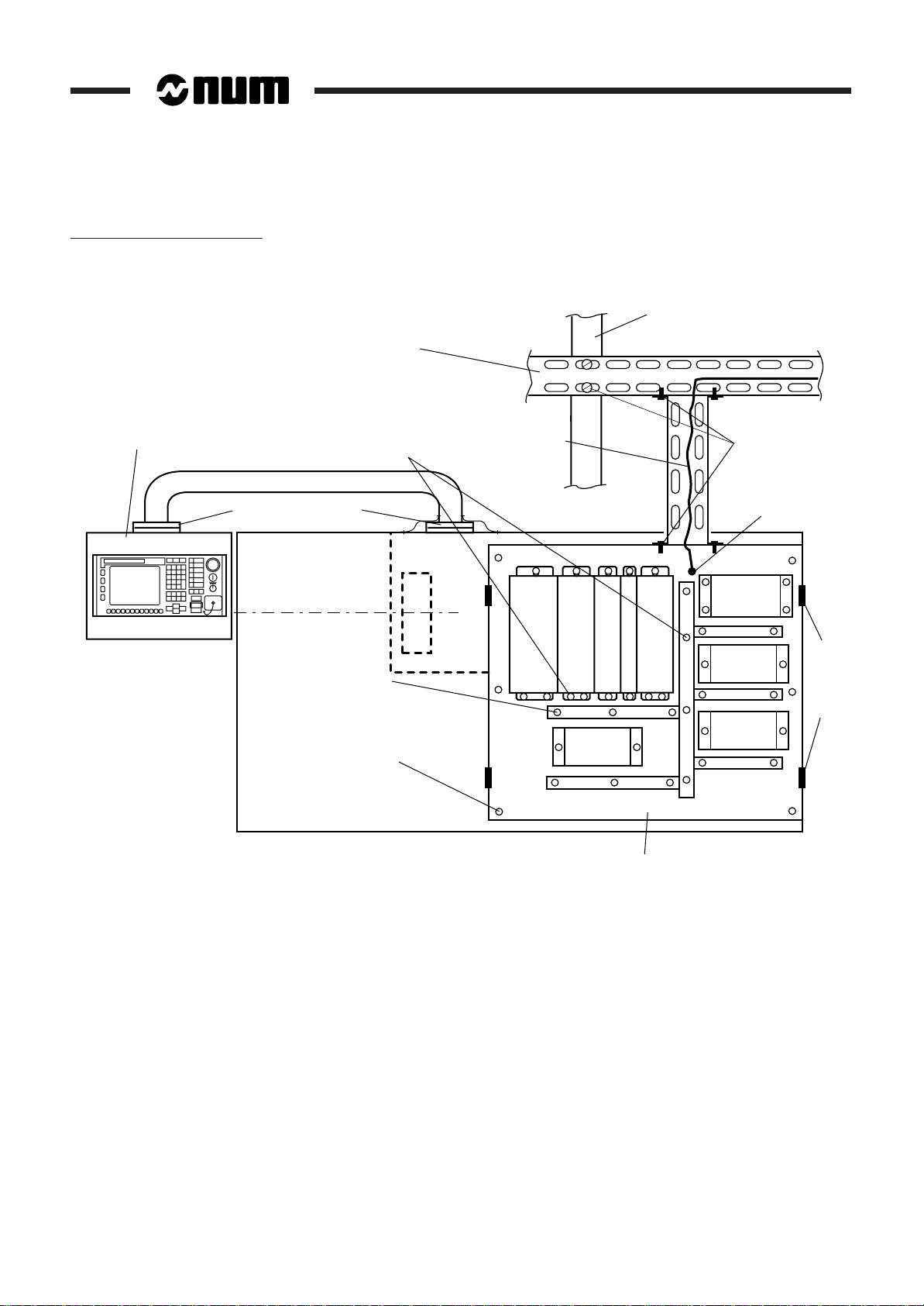
Example of Meshed System
Compact panel with zinc-plated
seal enclosure
(to be placed on a conductive
surface or connected by shunts)
Zinc- or cadmium-plated
metal cable trays
Metal frame equipment with
good electrical conductivity of
the attachment points
Protective
earthing wire
Structural beam
Electrical continuity
ensured
Pendant
Conductive hinges
or 2 bonding braids
Metal conduit with
conductive attachment
(recommended)
Cabinet attachment
points providing good
electrical continuity
Earth
D
D
D
R
R
R
I
V
E
1
RELAY
Metal power cabinet
N
I
I
U
V
V
E
E
M
3
2
1
0
4
0
Earthing terminal
Isolating
switch
RELAY
Door hinges
RELAY
Rear view of a lathe
In the units, the concepts of logical 0 V and protective earth coincide, i.e. the logical 0 V is connected in many points
to the frame earth.
to be shunted
The shieldings of logical signal cables are earthed at both ends. This contributes to the mesh and in addition, the
internal electronic circuitry and the enclosure are at the same potential.
To attenuate the loop effects thus created (the captured field depends on the loop area), the cables must be attached
against the conduit or metal walls. This is called cabling with "reduction effect".
In the case of separate power supply for the logical inputs and outputs, the 0 V lines of these power supplies must be
earthed and the wiring must be made with "reduction effect".
REMARK: Meshing the earths does not provide a protective system. The earthing terminals
on the units must be connected to the general earth electrode of the building.
1 - 8 en-938938/2
Page 22
1.4.3 Equipment Immunity
General Installation Instructions
Equipment immunity to electromagnetic interference is guaranteed by:
- attenuating the interference generated by the sources,
- reducing the coupling between source and sink,
- increasing the immunity (hardening) of the equipment.
The three methods are complementary and should be applied together.
1.4.3.1 Attenuation at the Source (Interference Suppression)
To limit the interference generated by components outside the system, make sure that:
- all the connections on terminal boards are securely attached,
- all the interference sources (relays, solenoid valves, motors, etc.) are provided with a suitable protection system.
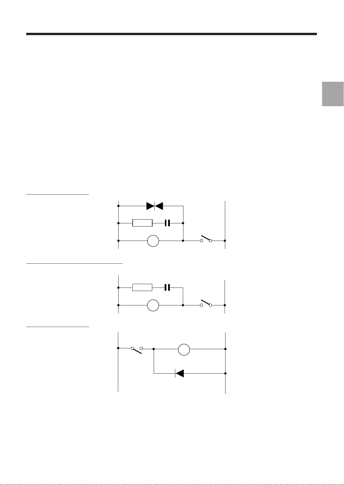
Examples
Low power AC contactor
Medium and high power AC contactor
1
Low power DC contactor
220 Ω
1W
0,47 µF
+–
en-938938/2 1 - 9
Page 23
Three-phase motor
M
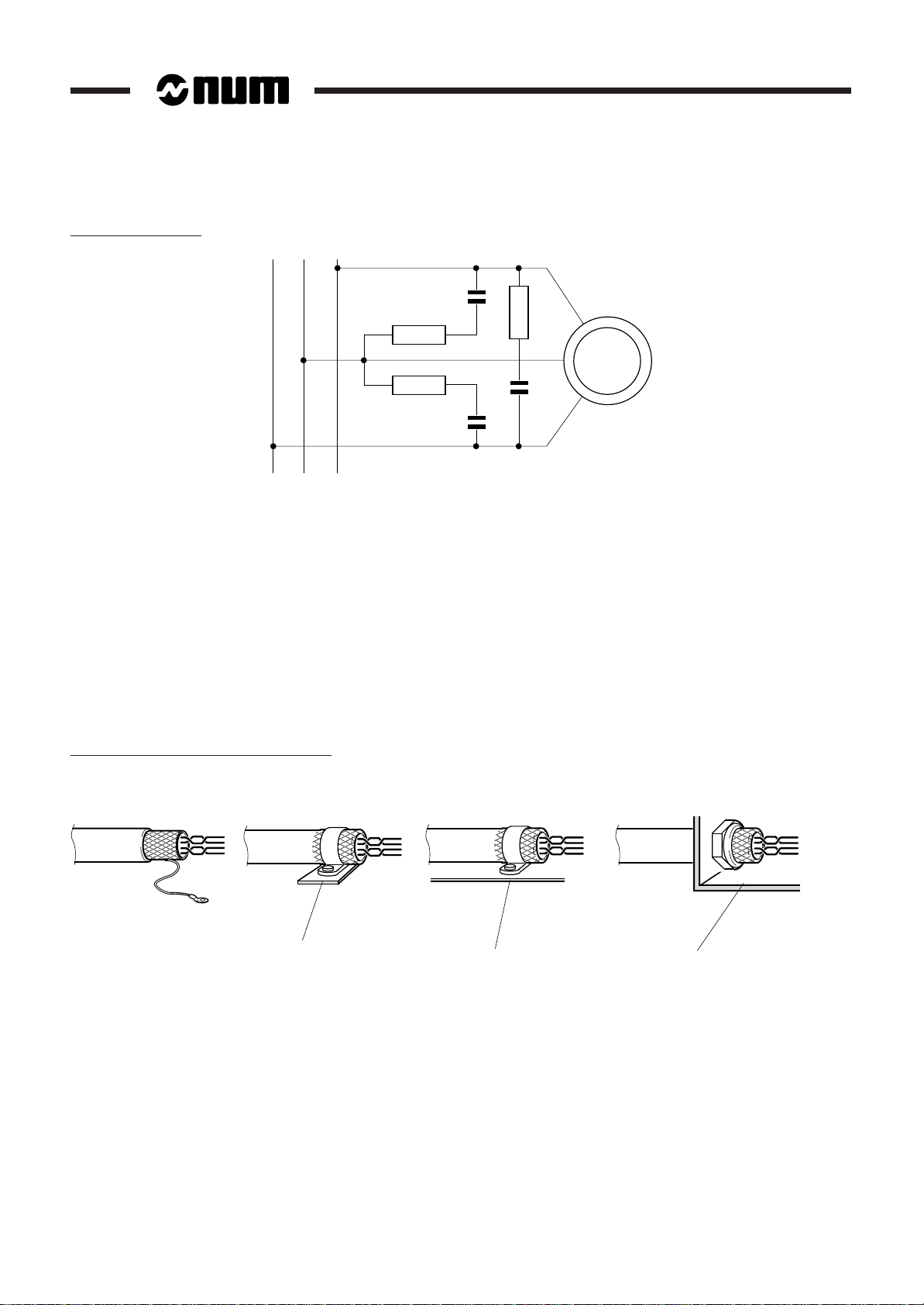
1.4.3.2 Reduction of Couplings
Provide a suitable earth meshing system (see Sec. 1.4.2.2) using metal parts with a conductive surface interconnected
(bolted) together.
Wire with a reduction effect (low area loops):
- cables supplied against conduits and metal parts forming the frame earth,
- forward and backward travel of a signal in the same cable (twisted pair).
Earth the shielding of logic signal cables at both ends.
Earth the cable shielding over 360 degrees:
- with a conductive gland to penetrate through a bulkhead,
- by pinching the shielding in metal covers that are suitably earthed for connector plugs.
Connection of shielding to frame earth
WRONG
ACCEPTABLE
Earthing rail
IDEAL, CONTACT
RIGHT
Frame Frame
OVER 360 degrees
1 - 10 en-938938/2
Page 24
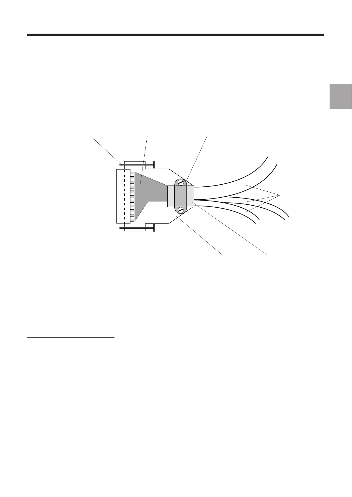
Connection of cable shielding to the cover of a connector plug
General Installation Instructions
Earth the cable shielding over 360 degrees: fold the shielding back onto the cable over a length of 1 cm and clamp
it in the cover clamp.
Attaching
screw
Sub.D connector
Wiring
location
Clamp
Half-cover
Cables
Cable
shieldings
1
Low level circuits must be separated from power circuits and circuits with interference:
- by physical separation of the cables (recommended minimum 30 cm),
- by routing in separate conduit or cable trays,
- by crossings at 90 degrees.
Analogue inputs (such as servo-drives) must be differential (common mode rejection).
Special case of servo-drive wiring
Servo-drives are low level (microvolt sensitivity), low frequency systems. It is therefore recommended to protect the
link by a screen earthed only on the CNC side (see Sec. 1.4.2.1) and to provide double shielding on the cable earthed
at both ends to serve for bonding.
When these recommendations cannot be applied (unavailability of cable with double shielding, etc.), bonding must
be given precedence by using a cable with single shielding earthed at both ends.
en-938938/2-E1 1 - 11
Page 25

1.4.3.3 Equipment Hardening
Hardening is a feature integrated in the equipment design. Special care was taken with equipment immunity:
- multilayer cards with internal ground plane,
- stainless steel enclosure around the system and front panels in good contact with the enclosure so that the
assembly forms an excellent Faraday cage,
- metal connector receptacles electrically connected to the front panels and provided with metal covers on which the
shielding is earthed over 360 degrees,
- high level mains filtering on the power supply input,
- optoisolated binary inputs and outputs with physical separation from interference circuits.
All these measures give the equipment excellent immunity to electromagnetic interference.
1 - 12 en-938938/2
Page 26
General Installation Instructions
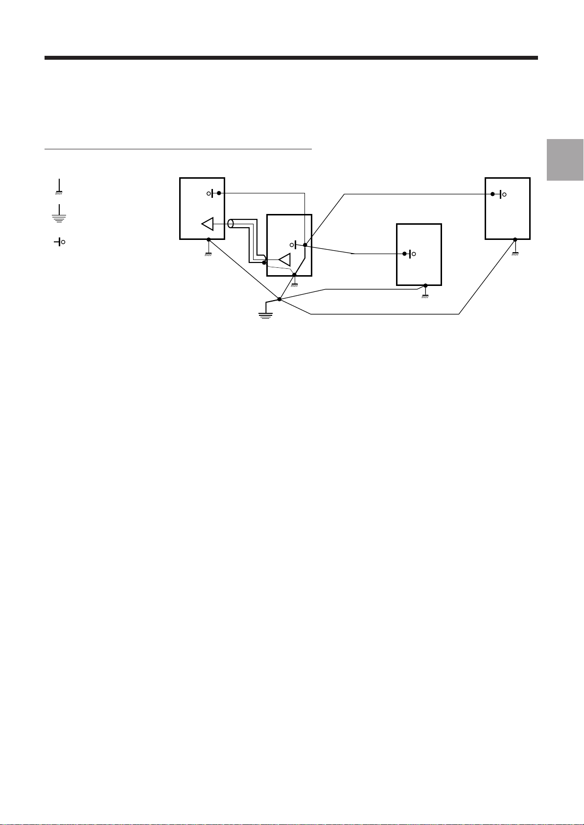
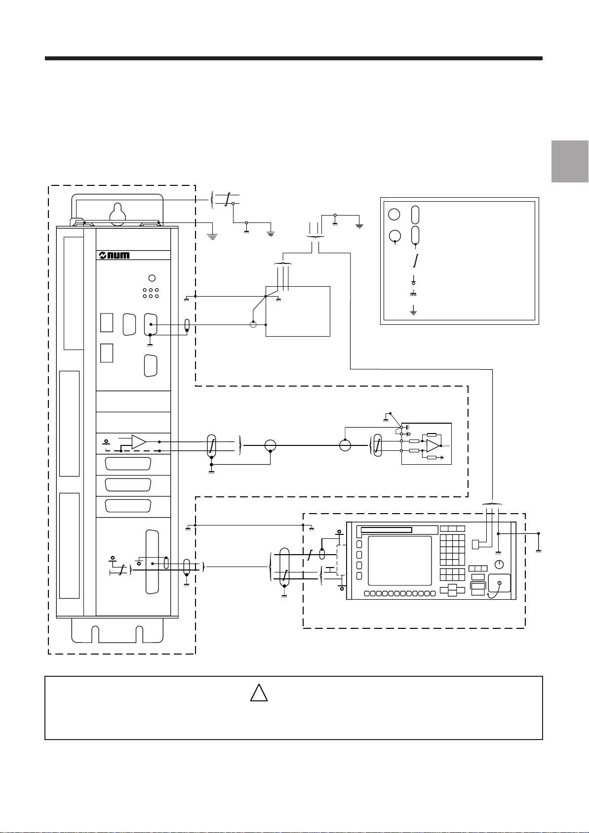
1.4.4 Diagram of the 0 V, Frame Earth and Operational Earth
1
Peripheral
Screen
(not mandatory)
24 VDC
Shielding
230 VAC
STORAGE
UNIT
Axes
Shielding
(not mandatory)
Screen
KEY
Shielding not earthed at this end
or
Shielded earthed at this end
or
Twisted wires
0 V
Frame earth
Operational earth
SERVO-DRIVE
Axis or spindle
POWER CABINET
5V
Video / Operator
panel
!
CAUTION
5V
Op. panel
PENDANT
The 0 V lines of the 24 VDC power supplies must mandatorily be
connected to the frame earth.
en-938938/2 1 - 13
Page 27

1.5 NUM Operator Panel Colours
The colours used for the NUM 1020 / 1040 operator panels are from standard colour ranges:
Colour Use Standard
Dark grey Background RAL 7021
Medium grey Keys RAL 7036
Light grey Keys RAL 7032
Red Side trim PANTONE WARM RED C
1.6 Screen Saver
The CNC has a screen saver designed to extend the screen life. When it is activated by the PLC programme, the screen
saver clears the screen after 5 minutes of no action on the keyboard. Pressing any key redisplays the previously active
page.
It is recommended to activate the screen saver by the PLC programme. This is done by setting the SC_SAVE bit
(%W5.7).
1 - 14 en-938938/2
Page 28

General System Description
2 General System Description
2.1 System Components 2 - 3
2.1.1 Operator Panels 2 - 3
2.1.1.1 Compact Panels 2 - 3
2.1.1.2 50-Key Panels 2 - 3
2.1.1.3 QWERTY Panels 2 - 3
2.1.2 1020 or 1040 Rack 2 - 4
2.1.4 Machine Panel 2 - 4
2.1.5 Additional Components 2 - 4
2.2 Basic Configuration 2 - 6
2.2.1 Basic 1020 Configuration 2 - 6
2.2.2 Basic 1040 Configuration 2 - 6
2.3 System Architecture 2 - 7
2.3.1 1020 or 1040 System with Compact Panel 2 - 7
2.3.2 1040 System with CNC Panel 2 - 8
2
en-938938/1 2 - 1
Page 29

2 - 2 en-938938/0
Page 30
2.1 System Components
2.1.1 Operator Panels
2.1.1.1 Compact Panels
10" Colour and 9" Monochrome Compacts Operator Panels
Subassemblies Weight (kg)
Panel 11
Video cable
General System Description
2
2.1.1.2 50-Key Panels
2.1.1.3 QWERTY Panel
10" Colour and 9" Monochrome Operator Panels
Subassemblies Weight (kg)
Panel 10,7
Video cable
14" Colour Operator Panel
Subassemblies Weight (kg)
Panel 16,5
Vidéo cable
en-938938/1 2 - 3
Page 31

2.1.2 1020 or 1040 Rack
Weight: 6 kg
2.1.4 Machine Panel
Subassemblies Weight (kg)
Machine panel 2.200
Optical fibres
Machine panel extension (optional) 0.300
Handwheel (optional) 0.515
2.1.5 Additional Components
32-Input Interface Module
Subassemblies Weight (kg)
Interface module 0.300
Input/output card connecting cable
24-Output Relay Module
Subassemblies Weight (kg)
Relay module 1.050
Input/output card connecting cable
2 - 4 en-938938/0
Page 32

General System Description
Axis Interface Module
Subassemblies Weight (kg)
Axis interface module 0.230
AXE
N°
Axis interface connecting cable
Handwheel
2
Weight: 0.615 kg
NUM Diskette Drive
Subassemblies
Diskette drive
Serial interface cable
en-938938/1 2 - 5
Page 33

2.2 Basic Configuration
2.2.1 Basic 1020 Configuration
NUM 1020 CPU
Compact panel + video cable
2.2.2 Basic 1040 Configuration
NUM 1040 CPU
Panel (compact, 50-key or QWERTY) + video cable
Machine panel (optional)
2 - 6 en-938938/0
Page 34

2.3 System Architecture
2.3.1 1020 or 1040 System with Compact Panel
Compact panel
Graphic
function
Memory
General System Description
2
Communication
function
Axes
CNC
function
PLC
function
Optional keyboard
RS 232E serial interface
RS 232E / RS 422A / RS 485 serial interface
FIP network interface
Speed reference
Measurement
Origin switch
Inputs
Outputs
Interrupt
Analogue inputs/output
REMARK A machine panel cannot be used with the compact panel.
en-938938/1 2 - 7
Page 35

2.3.2 1040 System with CNC Panel
Graphic
function
Memory
Panel
Or
Communication
function
Axes
CNC
function
PLC
function
Optical fibre
RS 232E serial interface
RS 232E / RS 422A / RS 485 serial interface
FIP network interface
Speed reference
Measurement
Origin switch
Inputs
Outputs
Machine
panel
Machine
panel extension
(I/O)
2 - 8 en-938938/0
Interrupt
Analogue inputs/output
Page 36

Overall Dimensions - Installation
3 Overall Dimensions - Installation
3.1 NUM 1020 and 1040 CPUs 3 - 3
3.1.1 CPU Mounting Parts 3 - 3
3.1.2 Overall Dimensions and Attachments of
the CPU 3 - 4
3.2 Compact Panel 3 - 5
3.2.1 Panel Mounting Parts 3 - 5
3.2.2 Overall Dimensions of the Compact Panel 3 - 6
3.2.3 Cutouts for Compact Panel Mounting 3 - 7
3.3 9" Monochrome and 10" Colour 3 - 8
3.3.1 Panel Mounting Parts 3 - 8
3.3.2 Overall Dimensions of the Panels 3 - 9
3.3.3 Cutouts for Panel Mounting 3 - 10
3.4 14" Colour QWERTY Panels 3 - 11
3.4.1 Panel Mounting Parts 3 - 11
3.4.2 Overall Dimensions of the Panel 3 - 12
3.4.3 Cutouts for Panel Mounting 3 - 13
3.5 Machine Panel 3 - 14
3.5.1 Machine Panel Mounting Parts 3 - 14
3.5.2 Overall Dimensions of the Machine Panel 3 - 15
3.5.3 Cutouts for Machine Panel Mounting 3 - 15
3.6 Additional Components 3 - 16
3.6.1 Mounting of the 32-Input Interfacing
Module 3 - 16
3.6.2 Mounting of the 24-Output Relay Module 3 - 16
3.6.3 Mounting of the Axis Connection Module 3 - 17
3.6.4 Handwheel Mounting 3 - 18
3.6.5 Mounting of the NUM Diskette Drive 3 - 19
3.6.6 Overall Dimensions of the Sub.D
Connector Covers (Cables) 3 - 20
3
en-938938/2 3 - 1
Page 37

3 - 2 en-938938/2
Page 38

3.1 NUM 1020 and 1040 CPUs
,,,,,,,,,,,,,,,,,,,,,,,,,,,,
,,,,,,,,,,,,,,,,,,,,,,,,,,,
,,,,,,,,,,,,,,,,,,,,,,,,,
,,,,,,,,,,,,,,,,,,,,,,,
,,,,,,,,,,,,,,,,,,,,,
,,,,,,,,,,,,,,,,,,,
,,,,,,,,,,,,,,,,,
,,,,,,,,,,,,,,,
,,,,,,,,,,,,,
,,,,,,,,,,,
,,,,,,,,,
,,,,,,,
,,,,,
,,,
,
Weight: 6 kg.
3.1.1 CPU Mounting Parts
1
Overall Dimensions - Installation
3
2
DC
24V
+
POWER
SUPPLY
-
1 - CPU
2 - Attaching screw and washer (3)
Output
Input
Reset
L3
L2
Pwr
L1
Fail
Def
C
o
m
S
e
1
r
i
R
a
e
l
I
c
t
/
A
n
a
E
m
Axis
P
a
n
e
l
en-938938/2 3 - 3
Page 39

3.1.2 Overall Dimensions and Attachments of the CPU
,
,
,
,
,
,
,
,
,
,
,
,
,
,
,
,
,
,
,
,
380
17
Output
Input
=
6.5
R
e
c
E
m
L1
DefL3Pwr
Axis
=
100
air flow
Clearance for
Reset
L2
Fail
S
C
e
o
r
m
i
a
1
l
I
t
/
A
n
a
276
8
Clearance
354100
P
a
n
e
l
for door opening
Contact surface
9
,,,,,,,,,,,,
,,,,,,,,,,,,
,,,,,,,,,,,,
,,,,,,,,,,,,
,,,,,,,,,,,,
,,,,,,,,,,,,
,,,,,,,,,,,,
,,,,,,,,,,,,
,,,,,,,,,,,,
,,,,,,,,,,,,
,,,,,,,,,,,,
,,,,,,,,,,,,
,,,,,,,,,,,,
,,,,,,,,,,,,
,,,,,,,,,,,,
,,,,,,,,,,,,
,,,,,,,,,,,,
,,,,,,,,,,,,
,,,,,,,,,,,,
,,,,,,,,,,,,
,,,,,,,,,,,,
24V
+
DC
POWER
SUPPLY
-
285100
cables
6.5 6.5
=
40 =
21.5 28.5
air flow
110
Clearance for
Clearance for
Front view Top view
REMARK It is not necessary to open the door except to add axis cards or an SRAM memory
chip or adjust the transmit power of the optical fibre line.
!
CAUTION
For correct ventilation, the CPU must be installed vertically.
3 - 4 en-938938/2
Page 40

3.2 Compact Panel
Weight: 11 kg.
3.2.1 Panel Mounting Parts
1
Overall Dimensions - Installation
3
ESC ?
%
G
E
M
N
F
7
/
H
S
x
8
X
T
9
4
Y
=
-
5
A
F1
F2
F3
F4
F5
F6
F7
F8
F9
F10
F11
F12
Z
6
1
B
!
+
2
C
P
D
3
Q
0
R
.
INSER
DEL END
2
1 - Panel
2 - Panel attaching screw and washer (6)
!
CAUTION
The panel is not sealed unless the cover is installed over the front panel connectors.
en-938938/2 3 - 5
Page 41

3.2.2 Overall Dimensions of the Compact Panel
220
483
F1 F2 F3 F4 F5 F6 F7 F8 F9 F10 F11 F12
271
ESC ?
G%ME/
7N8S9
4X5Y6
1A2B3
DP0
INSER
DEL END
Q.R
F
T-=
Z+!
C
80
308 (for 10") 37
H
x
202
266 (for 9")
180
16
Clearance
for cables
3 - 6 en-938938/2
150
60
Page 42

3.2.3 Cutouts for Compact Panel Mounting
Overall Dimensions - Installation
=202=
Cutout
211.6
6 M4 holes
211.5==
451
211.5
REMARK The cutout dimensions are the same as for the 50-key panels. Only the
attachment holes differ between the two types of panels.
!
CAUTION
It is recommended to make sure the enclosure over the rear part of the
panel provides IP65 insulation.
3
en-938938/2 3 - 7
Page 43

3.3 9" Monochrome and 10" Colour
Weight: 10.7 kg.
3.3.1 Panel Mounting Parts
1
3 - 8 en-938938/2
3
2
1 - Panel
2 - Edge trim
3 - Panel attaching screw and washer (4)
Page 44

3.3.2 Overall Dimensions of the Panels
Overall Dimensions - Installation
220
252
483
MACHINING PRESET
N%GHF
A
{
YBV(J)T
}
C
"
DPQ
E
SHIFT
Ctrl
HELP
MODE
70
294 (for 10") 30
1060
PROGRAM
EDIT
'
M
?
S
I;U:X
xoff
]
.>K[WZ
R
L
SPACE
TOOL
JOG
<
,
7&8 9
4$5 6
!
=/0-+
INS/
OVER
ENTER
LINE
DEL
CHAR
//
\ ~0
^
3#2@1
*
HOME
PgUp
END
PgDn
197
3
253 (for 9")
Clearance
for cables
16
183
62
en-938938/2 3 - 9
Page 45

3.3.3 Cutouts for Panel Mounting
2630
4 M6 holes
Cutout
4 dia. 10 mm holes
451= =
466
=180=
202
13 9
REMARK The cutout dimensions are the same as for the compact panel. Only the
attachment holes differ between the two types of panels.
!
CAUTION
It is recommended to make sure the enclosure over the rear part of the panel
3 - 10 en-938938/2
provides IP65 insulation.
Page 46

3.4 14" Colour QWERTY Panels
Weight: 16.5 kg.
3.4.1 Panel Mounting Parts
Overall Dimensions - Installation
1
3
3
2
1 - Panel
2 - Edge trim
3 - Panel attaching screw and washer (8)
en-938938/2 3 - 11
Page 47

3.4.2 Overall Dimensions of the Panel
483
F1
F3F2
!1@2#3$4%
ESC Q W E R T Y U I O P
CTRL A D F G HJKL
5^6&7*8(9)0_-+=+
S
x off
ALT
/
F8F7F6F5F4
MNBVCXZSHIFT SPACE
340
F9
:
,<.>/
F10
{
[}]
`";
F11 F12
`
?
400
35
290
JOGTOOL
MODE
M01
HELP
line
line
DEL
INS
char
char
ALL
home Pg Up
CAPS
VALID
Pg Dnend
399
40
70
20
3 - 12 en-938938/2
Clearance
for cables
97
60
Page 48

3.4.3 Cutouts for Panel Mounting
Cutout
Overall Dimensions - Installation
3
=235=
89 89 32.532.5
389
4 dia. 10 mm holes
8 M6 holes
451= =
466
!
CAUTION
It is recommended to make sure the enclosure over the rear part of the panel
provides IP65 insulation.
en-938938/2 3 - 13
Page 49

3.5 Machine Panel
Weight: 2.200 kg unequipped (add 0.300 kg for the extension and 0.515 kg for the handwheel).
3.5.1 Machine Panel Mounting Parts
3 - 14 en-938938/2
1
2
1 - Machine panel
2 - Machine panel attaching screw (4)
Page 50

3.5.2 Overall Dimensions of the Machine Panel
483
Overall Dimensions - Installation
177
280
122
80
3
3.5.3 Cutouts for Machine Panel Mounting
=
4 M6 holes
3
60
Overall dimensions with
the extension connecting cable
Overall dimensions without
extension
= 101.6
167
=
451
466
!
CAUTION
=
It is recommended to make sure the enclosure over the rear part of the panel
provides IP65 insulation.
en-938938/2 3 - 15
Page 51

3.6 Additional Components
3.6.1 Mounting of the 32-Input Interfacing Module
Weight: 0.300 kg.
86
MOD. INTERFACE 32 E
60
183
Mounted by snapping to extrusions complying with standards EN 50022 (or NF C 63-015) and EN 50035
(or NF C 63-018).
3.6.2 Mounting of the 24-Output Relay Module
Weight: 1.050 kg.
MOD. RELAYAGE 24 S
96
98
69
376
Mounted by snapping to extrusions complying with standards EN 50022 (or NF C 63-015) and EN 50035 (or NF C 63-
018).
3 - 16 en-938938/2
Page 52

3.6.3 Mounting of the Axis Connection Module
Weight: 0.230 kg.
!
ALIM
0 1
ADRESSE
PRESENCE TENSION
/B
ECLK
RCLK
/ECLK
Z.DATA
/Z.DATA
CAPTEUR REF VIT. BUTEE
/RCLK
ALIM CAPTEUR
700/800
BROCHE 2
0V
0V
PFD
PFD
PCH
MANIVE
BROCHE 1
/BUTEE
86
700/800 1000 INT. 5V EXT.
A/AB
2V
SPFD
SPCH
SALIS.
AXE
N°
AXE ANALOG.
INTERDIT
Overall Dimensions - Installation
1000
MANIVE
MANIVE
MANIVE
MANIVE
BROCHE
BROCHE
BROCHE
BROCHE
ALIM.EXT.
BUT
0VBUT
0V BUT
0V
5..24V
3
53
160
Mounted by snapping to extrusions complying with standards EN 50022 (or NF C 63-015) and EN 50035
(or NF C 63-018).
en-938938/2 3 - 17
Page 53

3.6.4 Handwheel Mounting
Overall dimensions
46.5
-
==
108
+
==
108
Holes and cutout
4 M5 holes
ø 63.5
3
52
62 60
35
3 - 18 en-938938/2
dia. 67 mm
7.5
89
==
==
89
Page 54

3.6.5 Mounting of the NUM Diskette Drive
Overall dimensions
Overall Dimensions - Installation
75
147
50
Clearance for cables
and switch
Holes and cutout
123
115= =
174
44
3
67
4 M4 holes
4313
Cutout
en-938938/2 3 - 19
Page 55

3.6.6 Overall Dimensions of the Sub.D Connector Covers (Cables)
C
Number of contacts A B C
9311641
15 53 16 38
25 53 16 45
37 70 24 51
B
A
REMARK The dimensions given in the table are rounded off and correspond to the product
line of a particular supplier. They could differ slightly for other suppliers.
3 - 20 en-938938/2
Page 56

Component Preparation
4 Component Preparation
4.1 Preparing the CPU 4 - 3
4.1.1 Opening the Fuse/Battery Cover 4 - 3
4.1.2 Opening the Cover Plate 4 - 4
4.1.3 Adding Axis Cards 4 - 6
4.1.4 Adding an SRAM Memory Module 4 - 9
4.1.5 Adjusting the Optical Fibre Transmit Power 4 - 10
4.1.6 Replacing or Installing the Battery 4 - 10
4.2 Preparing the Compact Panel 4 - 11
4.2.1 Removing the Rear Cover 4 - 11
4.2.2 Relocating the Keyboard Connector 4 - 12
4.2.3 Installing the Key Customisation Label 4 - 13
4.3 Preparing the Machine Panel 4 - 14
4.3.1 Assigning an Address to the Panel 4 - 14
4.3.2 Installing the Handwheel 4 - 15
4.3.3 Installing the Machine Panel Extension 4 - 16
4.3.4 Setting the Optical Fibre Transmit Power 4 - 17
4.3.5 Installing the Key Labels 4 - 18
4.4 General Operations 4 - 20
4.4.1 Replacing Fuses 4 - 20
4.4.1.1 1020/1040 CPU Fuses 4 - 20
4.4.1.2 10" Compact Panel Fuse 4 - 20
4.4.1.3 10" 50-Key Panel Fuse 4 - 20
4.4.1.4 Machine Panel Fuse 4 - 21
4.4.2 Wiring of the Watchdog, Safety Daisy
Chain 4 - 22
4
en-938938/2 4 - 1
Page 57

4 - 2 en-938938/2
Page 58

Component Preparation
4.1 Preparing the CPU
Operations that can be performed on the CPU:
- Adding axis cards (see Sec. 4.1.3),
- Adding an SRAM memory module (see Sec. 4.1.4),
- Adjusting the optical fibre transmit power (see Sec. 4.1.5),
- Replacing or installing the battery (see Sec. 4.1.6).
The first three operations require opening the cover plate (see Sec. 4.1.2) and the last requires opening the fuse/battery
cover (see Sec. 4.1.1).
4.1.1 Opening the Fuse/Battery Cover
Remove the screw and take off the cover.
Location of the fuse and battery:
1
R
e
Reset
L2
L1
DefL3Pwr
Fail
S
e
r
L1
DefL3Pwr
4
Screw
C
o
m
Reset
L2
Fail
Cover
2
3
1 - Battery
2 - Fuse
3 - Battery connector
en-938938/2 4 - 3
Page 59

4.1.2 Opening the Cover Plate
Remove the two screws and swing open the cover plate.
Screws
4 - 4 en-938938/2
Page 60

Location of the items concerned by the work:
Component Preparation
ON
1123
4
2
1 - Slot for SRAM memory module
2 - Optical fibre transmit power adjustment switches
3 - Axis cards
3
en-938938/2 4 - 5
Page 61

4.1.3 Adding Axis Cards
,,,,,,,,,,,,,,,,,,,,,,,,,,,,
,,,,,,,,,,,,,,,,,,,,,,,,,,,
,,,,,,,,,,,,,,,,,,,,,,,,,
,,,,,,,,,,,,,,,,,,,,,,,
,,,,,,,,,,,,,,,,,,,,,
,,,,,,,,,,,,,,,,,,,
,,,,,,,,,,,,,,,,,
,,,,,,,,,,,,,,,
,,,,,,,,,,,,,
,,,,,,,,,,,
,,,,,,,,,
,,,,,,,
,,,,,
,,,
,
,,,,,,,,,,,,,,,,,,,,,,,,,,
,,,,,,,,,,,,,,,,,,,,,,,,
,,,,,,,,,,,,,,,,,,,,,,
,,,,,,,,,,,,,,,,,,,,
,,,,,,,,,,,,,,,,,,
,,,,,,,,,,,,,,,,
,,,,,,,,,,,,,,
,,,,,,,,,,,,
,,,,,,,,,,
,,,,,,,,
,,,,,,
,,,,
,,
Refer to the layout diagram (see Sec. 4.1.2).
Remove the two screws and take off the card retaining bar.
DC
24V
+
POWER
SUPPLY
-
Reset
L3
L2
Pwr
L1
Fail
Def
C
o
m
S
e
1
r
i
R
a
e
l
I
c
t
/
A
n
a
E
m
Screw
Bar
Axis
P
a
n
e
l
Screw
4 - 6 en-938938/2
Page 62

Remove the screw and remove the card slot blanking plate.
Install the new card and tighten the screw.
Component Preparation
Screw
Blanking
plate
4
Axis card
!
CAUTION
When inserting a new card, push it straight into the connector so as not to damage the
connector pins.
en-938938/2 4 - 7
Page 63

Install the bar and tighten the screws.
,,,,,,,,,,,,,,,,,,,,,,,,,,,,
,,,,,,,,,,,,,,,,,,,,,,,,,,,
,,,,,,,,,,,,,,,,,,,,,,,,,
,,,,,,,,,,,,,,,,,,,,,,,
,,,,,,,,,,,,,,,,,,,,,
,,,,,,,,,,,,,,,,,,,
,,,,,,,,,,,,,,,,,
,,,,,,,,,,,,,,,
,,,,,,,,,,,,,
,,,,,,,,,,,
,,,,,,,,,
,,,,,,,
,,,,,
,,,
,
,,,,,,,,,,,,,,,,,,,,,,,,,,
,,,,,,,,,,,,,,,,,,,,,,,,
,,,,,,,,,,,,,,,,,,,,,,
,,,,,,,,,,,,,,,,,,,,
,,,,,,,,,,,,,,,,,,
,,,,,,,,,,,,,,,,
,,,,,,,,,,,,,,
,,,,,,,,,,,,
,,,,,,,,,,
,,,,,,,,
,,,,,,
,,,,
,,
DC
24V
+
POWER
SUPPLY
-
Reset
L3
L2
Pwr
L1
Fail
Def
C
o
m
S
e
1
r
i
R
a
e
l
I
c
t
/
A
n
a
E
m
Axis
P
a
n
e
l
4 - 8 en-938938/2
Page 64

4.1.4 Adding an SRAM Memory Module
Refer to the layout diagram (see Sec. 4.1.2).
Position the module at a slant into the connector with the polarising
slot located on the right (1).
Swing the module up to a vertical position until it snaps in place (2).
Component Preparation
4
Polarising slot
1
2
en-938938/2 4 - 9
Page 65

4.1.5 Adjusting the Optical Fibre Transmit Power
The adjustment is made on switches (see Sec. 4.1.2) according to the length of the optical fibre cable:
Optical fibre cable length Switch setting
ON
L ≤ 15 m
123
ON
15 m < L ≤ 30 m
123
ON
L > 30 m
123
4.1.6 Replacing or Installing the Battery
Refer to the layout diagram (see Sec. 4.1.1).
!
CAUTION
The battery must be replaced within 15 minutes so as not to lose the data present in the
RAM. A special capacitor powers the SRAM modules while the battery is being replaced.
Remove the battery from its housing and take off the connector.
Connect the new battery, making sure the connector is correctly installed,
and install the battery.
4 - 10 en-938938/2
Page 66

4.2 Preparing the Compact Panel
Operations that can be performed on the compact panel:
- Relocation of the DIN connector (see Sec. 4.2.2),
- Installation of the key customisation label (see Sec. 4.2.3).
These operations require removing the rear cover (see Sec. 4.2.1).
4.2.1 Removing the Rear Cover
Remove the three screws and take off the cover.
Component Preparation
Screws
Location of the items concerned by the operations:
Cover
Rear view
Label installation slot
4
DIN connector support
en-938938/2 4 - 11
Page 67

4.2.2 Relocating the Keyboard Connector
The compact panel is equipped with a keyboard connector (5-contact DIN connector) accessible on the front after
removing the cover.
This location of the DIN connector corresponds to occasional use of a PC type keyboard (seal not ensured when the
cover is removed).
For permanent connection of a PC type keyboard, the DIN connector can be moved to the back of the panel:
DIN connector support
attaching nuts
DIN connector located on the front DIN connector relocated on the back of the panel
Unscrew the two DIN connector support attaching nuts.
Turn over the support and reinstall the nuts.
4 - 12 en-938938/2
Page 68

Component Preparation
4.2.3 Installing the Key Customisation Label
The compact panel has six cutomisable keys. The key assignments are identified by a label at the rear of the panel.
Customising the Label Supplied with the Compact Panel:
18
Marking areas
The label can be customised by transfers (Letraset type), Universe 54 font, pitch 12.
Installing the Label on the Rear of the Compact Panel:
18
18
18
18
18
4
en-938938/2 4 - 13
Page 69

4.3 Preparing the Machine Panel
4.3.1 Assigning an Address to the Panel
Set the address on the thumbwheel: address 1 to 4, different for
each panel.
4 - 14 en-938938/2
Page 70

Component Preparation
4.3.2 Installing the Handwheel
The handwheel is installed on the machine panel without its bezel (remove the cap by cutting the plastic pins with
cutting pliers):
1
4
2
3
1 - Handwheel body
2 - Attaching screw (3)
3 - Bezel attached by two screws
!
CAUTION
The handwheel could interfere with installation of the key labels.
It is therefore recommended to install the labels (see Sec. 4.3.5) before the handwheel.
en-938938/2 4 - 15
Page 71

4.3.3 Installing the Machine Panel Extension
The machine panel extension is installed at the rear of the machine panel.
It requires removing the enclosure.
2
1
4 - 16 en-938938/2
3
5
1 - Machine panel
2 - Machine panel extension
3 - Enclosure
4 - Screws (8)
5 - Spacers (5)
4
Page 72

Component Preparation
4.3.4 Setting the Optical Fibre Transmit Power
The setting is made on the rear of the machine panel according to the optical fibre cable length:
4
Optical fibre cable length Switch settings
3
L ≤ 15 m
15 m < L ≤ 30 m
L > 30 m
2
1
ON
3
2
1
ON
3
2
1
ON
en-938938/2 4 - 17
Page 73

4.3.5 Installing the Key Labels
The keys on the machine panel are not engraved. Their assignment is specified by installing a set of labels in windows
1 to 7 at the rear of the machine panel.
These labels can be:
- The standard labels provided by NUM
- Labels customised for the user.
Set of Labels Supplied with the Machine Panel
ILL10 0001 000100101
Window 1
JOG label
Window 1
customisable
M01
+
X
-
Z
-
X
+
Y
-
X
-
Y
+
Z
+
X
+
C
-
C
+
Z
-
Z
Window 2
Window 3
turning
Window 4
turning
Window 5
turning
Window 3
milling
Window 4
milling
Window 5
milling
Axis
control
labels
4 - 18 en-938938/2
Windows 2 to 5
customisable
Window 6
customisable
Window 7
Window 7
customisable
Machine function
label
Mode label
Page 74

Installing the Labels at the Rear of the Machine Panel:
Component Preparation
1
2
3
4
5
7
6
4
Customising the Labels
The labels can be customised by transfers (Letraset type), Universe 54 font pitch 12.
en-938938/2 4 - 19
Page 75

4.4 General Operations
4.4.1 Replacing Fuses
Accessible fuses:
Location Characteristics
1020/1040 CPU Slow-blow 2 A, 5 x 20 glass fuses
10" compact panel Fast-blow 2 A, 250 V, 5 x 20 glass fuse
10" 50-key panel Fast-blow 2 A, 250 V, 5 x 20 glass fuse
Machine panel Fast-blow 500 mA, 250 V, 5 x 20 glass fuse
4.4.1.1 1020/1040 CPU Fuses
Refer to the layout diagram (see Sec. 4.1.1)
Unscrew the fuse-holder cover (quarter-turn fastener).
Replace the blown fuse.
Install and screw on the fuse-holder cover.
4.4.1.2 10" Compact Panel Fuse
Unscrew the fuse-holder cover (quarter-turn fastener).
Replace the blown fuse.
Install and screw on the fuse-holder cover.
4.4.1.3 10" 50-Key Panel Fuse
Unscrew the fuse-holder cover (quarter-turn fastener).
Replace the blown fuse.
Install and screw on the fuse-holder cover.
?
E
M
F
/
H
S
x
8
T
9
Y
=
-
5
Z
6
B
!
+
2
C
3
Q
0
R
.
INSER
4 - 20 en-938938/2
Page 76

4.4.1.4 Machine Panel Fuse
Replace the blown fuse.
Component Preparation
Rear view
4
en-938938/2 4 - 21
Page 77

4.4.2 Wiring of the Watchdog, Safety Daisy Chain
The watchdog (WD) is the machine processor status signal. When WD = 0, the machine processor is faulty and the
programmed safety devices are therefore triggered.
The watchdog output is set by PLC programming: WD is the first output (OUT.0) of the CPU or machine panel
extension.
CAUTION
!
The CNC may continue to control the axes when WD = 0, which could cause problems
(collisions, etc.).
The WD output must therefore be wired in the safety chain so that when WD = 0, power
supply to the axes is cut off.
The system should remain on, to allow troubleshooting and setting of certain logic inputs
(which are not the only possible cause of failure).
Recommended safety daisy chain:
CNC ready WD CNC on
CNCr monitor WD monitor CNC on Power supply
CNCr: CNC ready
Off pushbutton
On pushbutton Power supply
WD monitor CNC on
CNCr monitor WD monitor
CNCr monitor
4 - 22 en-938938/2
Page 78

Component Preparation
This diagram is used to check that the WD and CNCr relays are not operated at power on.
No timeoutre used.
Powering up of the CNC is not enabled unless the watchdog and CNCr relay are deenergised.
When the CNC is on, the PLC programme closes the CNCr relay.
Power application is determined by the presence of WD and CNCr.
4
en-938938/2 4 - 23
Page 79

4 - 24 en-938938/2
Page 80

Interconnections
5 Interconnections
5.1 CNC/Peripheral Interconnections 5 - 3
5.2 NUM 1020 and 1040 CPUs 5 - 4
5.2.1 Power Supply 5 - 5
5.2.2 Connection to the Compact or CNC Panels 5 - 6
5.2.3 Optical Fibre Connecting Cable to the
Machine Panels 5 - 7
5.2.4 Analogue Inputs/Output and Interrupt 5 - 8
5.2.4.1 General 5 - 8
5.2.4.2 Analogue/IT Link Connecting Diagram 5 - 9
5.2.5 Communications 5 - 10
5.2.5.1 General 5 - 10
5.2.5.2 Serial Line Connection Diagram 5 - 10
5.2.6 Incremental and Absolute Axis Encoder
Cards 5 - 11
5.2.6.1 General 5 - 11
5.2.6.2 Voltage Across the Sensor 5 - 12
5.2.6.3 Maximum Incremental Sensor Channel
Output Frequency (Incremental or
Combined Sensors) 5 - 13
5.2.6.4 Setting the Reference Signal (Rules with
Encoded Distance Reference Marks) 5 - 13
5.2.6.5 Synchronous Serial Interface Timing
Diagram 5 - 14
5.2.6.6 Maximum Available Current per Axis 5 - 14
5.2.6.7 Setting the Origin Switch 5 - 15
5.2.6.8 Setting the Origin Switch (SSI or Combined
Sensor with semiabsolute Measurement) 5 - 16
5.2.6.9 Homing of SSI or Combined Sensors with
Absolute Measurement 5 - 16
5.2.6.10 Axis Connection Diagram 5 - 17
5.2.6.11 Handwheel Connection Diagram 5 - 18
5.2.7 Discrete Inputs 5 - 19
5.2.7.1 Input Characteristics 5 - 19
5.2.7.2 Connection Diagram for Inputs with
Interface Module 5 - 21
5.2.7.3 Interface Module Connections and
Customisation 5 - 23
5.2.7.4 Connection Diagram for Inputs without
Interface Module 5 - 25
5.2.8 Outputs 5 - 27
5.2.8.1 Output Characteristics 5 - 27
5.2.8.2 Output Connection Diagram with Relay
Module 5 - 30
5.2.8.3 Relay Module Connections and
Customisation 5 - 32
5.2.8.4 Connection Diagram for Outputs without
Relay Module 5 - 34
5
en-938938/0 5 - 1
Page 81

5.3 Compact Panel 5 - 36
5.3.1 General 5 - 36
5.3.2 Compact Panel Connection Diagram 5 - 37
5.4 CNC Panels 5 - 38
5.4.1 General 5 - 38
5.4.2 Panel Connection Diagram 5 - 39
5.5 Machine Panel 5 - 40
5.5.1 General 5 - 40
5.5.2 Machine Panel Connection Diagram 5 - 41
5.5.3 Machine Panel Extension 5 - 42
5.5.3.1 General 5 - 42
5.5.3.2 Connection Diagram of the Machine Panel
Extension with Remote Modules 5 - 43
5.5.3.3 Machine Panel Extension Connection
Diagram without Remote Modules 5 - 44
5.6 NUM Diskette Drive 5 - 45
5.6.1 General 5 - 45
5.6.2 Connections of the NUM Diskette Drive 5 - 45
5.6.2.1 Connection of the NUM Diskette Drive to
an RS 232E Line 5 - 45
5.6.2.2 Connection of the NUM Diskette Drive with
a Remote RS 232E Line 5 - 46
5.6.2.3 Connection of the NUM Diskette Drive to
an RS 422A Line 5 - 46
5.6.2.4 Connection of the NUM Diskette Drive with
a Remote RS 422A Line 5 - 47
5 - 2 en-938938/2
Page 82

5.1 CNC/Peripheral Interconnections
Interconnections
PC or PS
FIPWAY network
Machine panels*
I/O extension*
Machine tool
Power cabinet
Automatic controls
Output
Input
R
e
c
E
m
L1
DefL3Pwr
S
e
r
i
a
l
Axis
Reset
Fail
Diskette
drive
L2
C
o
m
1
I
t
/
A
n
a
Analogue
inputs/outputs
Printer
5
External interrupt
Motor
P
a
n
e
l
Servodrive
Sensor or
rule
Handwheel
or
Compact panel
or
50-key panel*QWERTY panel*
∗ Not available on NUM 1020
REMARK A machine panel cannot be used with the compact panel.
en-938938/0 5 - 3
Page 83

5.2 NUM 1020 and 1040 CPUs
The NUM 1020 and 1040 CPUs are 68020 microprocessor-based 32-bit processors.
Communication function
The NUM 1020 and 1040 CPUs can communicate with peripherals via the Com 1 serial (RS 232E) and Serial (RS
232E, RS 422A or RS 485) lines.
PLC function
The NUM 1020 and 1040 CPUs manage the machine environment via inputs and outputs:
- 32 inputs and 24 outputs with the 32-24 I/O card, or
- 64 inputs and 48 outputs with the 64-48 I/O card.
The machine panel extension can manage an additional number of 32 inputs and 24 outputs (1040 only).
An analogue I/O connector allows connection of the NUM 1020 and 1040 CPUs to:
- one interrupt input
- one analogue output
- two analogue inputs.
CNC function
The NUM 1020 and 1040 CPUs use the CNC software to manage part programmes and machining data, compute
paths and speeds and monitor axis movements.
Panel management function
The NUM 1020 and 1040 CPUs manage the VDU and keyboard.
Mass memory function
The NUM 1020 and 1040 CPUs store the operating programmes in REPROM, and the machine processor
programmes and user files in RAM with backup.
Backup for the files in RAM is provided by a battery with an operating time of 18 months.
!
CAUTION
The battery must mandatorily be replaced (see Secs. 4.1.1 and 4.1.6) after 18 months of
use (connected).
5 - 4 en-938938/2
Page 84

5.2.1 Power Supply
,
,
,
,
,
,
,
,
,
,
,
,
,
,
,
,
,
,
,
Power supply voltage 24 VDC nominal (19.2-30 VDC)
Maximum power 40 W
24 VDC
power supply
Interconnections
1
,,,,,,,,,,,,
,,,,,,,,,,,,
,,,,,,,,,,,,
,,,,,,,,,,,,
,,,,,,,,,,,,
,,,,,,,,,,,,
,,,,,,,,,,,,
,,,,,,,,,,,,
,,,,,,,,,,,,
,,,,,,,,,,,,
,,,,,,,,,,,,
,,,,,,,,,,,,
,,,,,,,,,,,,
,,,,,,,,,,,,
,,,,,,,,,,,,
,,,,,,,,,,,,
,,,,,,,,,,,,
,,,,,,,,,,,,
,,,,,,,,,,,,
24V
+
DC
POWER
SUPPLY
-
5
M5 holes
1 - Power cable (see Sec. 6.5.1)
Top view
en-938938/0 5 - 5
Page 85

5.2.2 Connection to the Compact or CNC Panels
1 2
1 - Video/panel cable (for lengths, see tables)
2 - Compact of CNC panel
The minimum video cable curve radius is 110 mm.
The video/panel cables are available in two versions:
- video interconnection kit (for wiring, see Sec. 6.6),
- video cable assembled.
Video interconnection kits:
Length P/N Length P/N
5 m ∗ 206203223 30 m 206203231
10 m ∗ 206203225 40 m 206203233
15 m 206203227 to order 206203235
20 m 206203229
∗ Only the 5 and 10 m cables can be used to the compact panel.
Assembled video cables:
Length P/N Length P/N
5 m 206202394 10 m 206202395
5 - 6 en-938938/2
Page 86

5.2.3 Optical Fibre Connecting Cable to the Machine Panels
The CPU is connected to the machine panels by an optical fibre ring as shown below:
1
Em
Interconnections
Rec
Em
Rec
1 - Optical fibre
The minimum optical fibre cable curve radius is 50 mm.
The transmit power must be set according to the length of the optical fibre connecting the transmitter of an item to the
receiver of the next item (see Sec. 4.1.5 for the CPU and Sec. 4.3.4 for the machine panels).
The machine panel addresses are set on a thumbwheel (see Sec. 4.3.1).
Rec
Em
5
When the optical fibre link is not used (CPU with optical fibre function), the transmitter must be connected to the receiver
by an optical fibre shunt:
Rec
Em
en-938938/0 5 - 7
Page 87

5.2.4 Analogue Inputs/Output and Interrupt
5.2.4.1 General
Analogue Inputs
Two inputs can be dedicated to connection of resistive potentiometers
Typical potentiometer rating 10 kΩ
Resolution 0.4 percent full scale
Power supply + 5 V
Analogue output
Output voltage - 10 / + 10 V
Minimum load 2 kΩ
Resolution 20 mV
External Interrupt
Maximum current draw 20 mA
Minimum current required 10 mA
Input on 5 V Logic "0" between 0 and 1 V
Logic "1" between 3.5 and 5.5 V
Input on 24 V Logic "0" between 0 and 4.7 V
Logic "1" between 18 and 27 V
IT time Programmable: T1 = 0,5/250/500/2220/4440 ms
Masking between two ITs Programmable: T2 = 1/500/1000/4000/8000 ms
Interrupt timing diagram:
Rising edge active
Falling edge active
t ≥ T1 t ≥ T2
IT Masking
5 - 8 en-938938/2-E1
Page 88

5.2.4.2 Analogue/IT Link Connecting Diagram
1
Analogue data:
spindle speed
and feed rate
override
potentiometers,
temperature probe
Analogue
process
control:
spindle,
flow control
Interconnections
5
Interrupt
1 - Analogue I/O - interrupt cable (see Sec. 6.3)
en-938938/0 5 - 9
Page 89

5.2.5 Communications
5.2.5.1 General
Serial line RS 232E (Com 1)
Multistandard serial line RS 232E, RS 422A or RS 485 (Serial)
Data rate 300 to 38.400 bauds (the data rate is limited to 19,200 bauds if two serial lines
are used)
The serial lines allow the CPU to exchange data with peripherals such as a PC or PS, a diskette drive and/or printer.
5.2.5.2 Serial Line Connection Diagram
1
applications
1 - Serial interface cable
- RS 232E (Com 1 or Serial: see Sec. 6.1.1)
- RS 422A (Serial only: see Sec. 6.1.2)
- RS 485 (Serial only: see Sec. 6.1.3)
NUM
or
user
or
Peripheral
5 - 10 en-938938/2
Page 90

Interconnections
5.2.6 Incremental and Absolute Axis Encoder Cards
5.2.6.1 General
Number of axes controlled Maximum 6
Servo-drive analogue output 1 -10 V/+10 V 14-bit + sign output per axis
Switch contact 1 24 V input per axis (19.2 to 30 V including 5% ripple)
Switch input impedance 2.15 kΩ∗ (2 to 2.4 kΩ)
Switch input current 11 mA minimum ∗ (7.5 mA on the old interface models)
∗ for interfaces with index E or above (interface P/N 204 203 382)
The axis interfaces allow the CNC to control the axes: control of the servo-drives and processing of the encoder data.
There are three types of axis measurements:
- Incremental measurement,
- absolute measurement by SSI (serial synchronous interface) link,
- measurement by rule with encoded distance reference marks.
5
Position Sensors Approved by NUM
Incremental sensors: ROD 428B (HEIDENHAIN, DG 60L (STEGMANN), ENH 2E7C55 (CODECHAMP) and C315805 (MCB).
Incremental rule with encoded distance reference marks: LS 706C + EXE 612 (HEIDENHAIN).
Absolute single- or multiturn SSI (Synchronous Serial Interface) sensors: ROC 424 (HEIDENHAIN), AG 66 and AG
661 (STEGMANN).
Combined sensors (SSI + incremental): ECN 1313 + IBV 610, EQN 1325 + IBV 650, ROC 412 + IBV 610 and RCN
619 (HEIDENHAIN).
Requirements Concerning Sensors and Their Power Supply
The installation of a sensor is subjected to several requirements:
- minimum sensor power supply voltage (see Sec. 5.2.6.2),
- maximum frequency above which the signals provided by the sensor are no longer counted with accuracy by the
system (incremental channels, see Sec. 5.2.6.3),
- maximum available current for supply of the sensors (see Sec. 5.2.6.6).
These requirements determine:
- the minimum power cable size,
- the maximum cable lengths,
- the need or not for an external power supply.
In the case of incremental and semiabsolute sensors, the origin switch must be set after installation.
Consumption of the Axis Interface Module
The specific consumption of the axis interface module is:
- 14 mA maximum on the sensor power supply ("Power on" LED),
- 7 mA maximum on the switch power supply ("/SWITCH" LED)
en-938938/0 5 - 11
Page 91

5.2.6.2 Voltage Across the Sensor
When installing a position sensor, it is necessary to provide the minimum power supply voltage related to the type of
sensor used.
5 VDC Sensors
When the NUM power supply is used, the voltage across the sensor is given by the equation:
Vs = 4.95 - (0.45 + 36.8 x 10⁻³ x L/S) x I
where:
- Vs (in V) is the voltage across the sensor,
- L (in m) is the cable length (one way only),
- S (in mm2) is the power conductor cross-sectional area,
- I (in A) is the current through the sensor.
The minimum wire size of the power supply conductors is calculated from the maximum current through the sensor,
the minimum voltage across the sensor and the required wire length.
It is recommended not to use wires with a cross-sectional area above 2.624 mm2. If a larger size is required, the use
of an external power supply located near the sensor can reduce the required wire size.
Example of a 5 V ± 5 percent sensor, current rating 220 mA
The computed voltage (Vs) must not be less than 4.75 V.
The table below gives the calculation results obtained for different cable lengths using the NUM power supply:
Cable length Minimum cross-sectional area Voltage across the sensor
20 m 1.65 mm
30 m 2.624 mm
2
2
4.753 V
4.758 V
Above 30 m, the wire size required would be above 2.624 mm2. In this case, use an external power supply whose
characteristics provide a minimum voltage of 4.75 V across the sensor while preserving a reasonable wire size.
Sensors Requiring a Power Supply Voltage Above 5 VDC
The use of an external power supply is mandatory.
5 - 12 en-938938/2
Page 92

Interconnections
5.2.6.3 Maximum Incremental Sensor Channel Output Frequency (Incremental or Combined
Sensors)
The diagram below shows the waveform of the signal on sensor channels A and B:
e
T
Channel A
a
Channel B
Pulses
Te : signal period on one of the channels
a : time between two edges
The sensor channel output frequency fe = 1 / T
e
Extreme values allowing correct signal detection by the system:
- Maximum frequency: f
- Minimum time between two edges: a
= 1.8 MHz
e max
= 138 ns.
min
The minimum time between two edges allowing correct signal detection by the system depends on the length and type
of cable used. The table below gives the results of tests conducted with [4 x (2 x 0.14 mm2)] shielded cables connecting
the sensor to the axis encoder card and using an external power supply:
Cable length Minimum time between two edges
10 m 147 ns
20 m 156 ns
50 m 250 ns
5
5.2.6.4 Setting the Reference Signal (Rules with Encoded Distance Reference Marks)
The reference signal (Z pulse) must be set for an electrical angle of 90 degrees. This setting can be made on the EXE
or IBV units.
en-938938/0 5 - 13
Page 93

5.2.6.5 Synchronous Serial Interface Timing Diagram
T
Sensor clock
Data channel
New sensor
data available
f
= 1/T: minimum 100 kHz, maximum 2 MHz
clock
Tv: minimum 50 ns, maximum T
synchronisation and data bits: maximum 32 bits
status bits: maximum 4 bits
parity bit: maximum 1 bit.
T
v
REMARK The synchronisation bits are leading 0’s in the frame (not present in mode
encoders).
Depending on the clock frequency and sensor cable length L, the clock output is connected to the clock input on the
interface or the sensor:
Sensor clock frequency Connection to interface Connection to sensor
100 kHz L < 400 m L < 400 m
200 kHz L < 200 m L < 250 m
400 kHz L < 60 m L < 150 m
500 kHz L < 50 m L < 100 m
800 kHz L < 30 m L < 85 m
1 MHz L < 20 m L < 75 m
1.6 MHz L < 5 m L < 60 m
2 MHz ---- L < 50 m
5.2.6.6 Maximum Available Current per Axis
Each axis interface can supply a maximum of 350 mA.
The current draw of all the sensors connected cannot exceed 1.5 A.
Above these values, an external power supply should be used.
5 - 14 en-938938/2
Page 94

5.2.6.7 Setting the Origin Switch
Homing is carried out on the zero pulse following opening of the origin switch:
Homing direction
Om
Contact closed Contact open
Interconnections
5
Sensor zero pulse
1 / 4 1 / 4
The switch must be set so that the contact opens between one-quarter and three-quarters of the distance separating
two zero pulses. This is to avoid coincidence between switch operation and the zero pulse, which could cause a
random shift by a distance equal to that separating two zero pulses.
The switch size should be such that the contact opens before detection of the sensor zero pulse and remains open
until the axis stops after detection of the zero pulse.
Useful area
1 sensor revolution
en-938938/0 5 - 15
Page 95

5.2.6.8 Setting the Origin Switch (SSI or Combined Sensor with semiabsolute Measurement)
The axis travel exceeds the sensor measurement travel. Homing is carried out on opening of the origin switch. It is
used to identify the sensor revolution on which the switch operates:
Homing direction
Contact closed Contact open
Sensor zero
pulse
Sensor zero pulse
1 / 4 1 / 4
Useful area
1 sensor revolution
The electrical contact opening signal must be clean, without bounce.
The switch must be set so that the contact opens between one-quarter and three-quarters of the distance separating
two zero pulses. This is to avoid coincidence between switch operation and the zero pulse, which could cause a
random shift by a distance equal to that separating two zero pulses.
The switch size should be such that the contact opens before detection of the sensor zero pulse and remains open
until the axis stops after detection of the open contact on the switch input.
5.2.6.9 Homing of SSI or Combined Sensors with Absolute Measurement
The axis travel is less than the sensor measurement travel. Homing is made at any point of the axis travel at power
on or after a reset of the CNC.
The axis connector switch input should not be wired.
REMARK The sensor zero pulse must be outside the axis travel.
5 - 16 en-938938/2
Page 96

5.2.6.10 Axis Connection Diagram
Interconnections
2
Sensor
3
Servo-drive
External
power supply
Switch
1
Servo-drive
5
Switch
External
power supply
Sensor
Connection of an axis to an axis interface
1 - Axis cable (see table)
Connection of an axis via an axis interface module
2 - Axis cables (see table)
3 - Axis interface module (P/N 263900000) and cable 1.5 m long
(P/N 260900000)
Axis type Power supply Cable alone Cable with interface
(see Sec.) module (see Sec.)
Encoded supplied by the interface 6.2.1.1 6.2.1.2 and 6.2.7
external 6.2.1.1 and 6.2.6 same as cable alone
Absolute SSI measurement supplied by the interface 6.2.2.1 6.2.2.2 and 6.2.7
external 6.2.2.1 and 6.2.6 same as cable alone
Semiabsolute SSI supplied by the interface 6.2.3.1 6.2.3.2 and 6.2.7
measurement external 6.2.3.1 and 6.2.6 same as cable alone
Combined: SSI + incremental supplied by the interface 6.2.4.1 6.2.4.2 and 6.2.7
Sinusoidal pulses external 6.2.4.1 and 6.2.6 same as cable alone
Combined: SSI + incremental supplied by the interface 6.2.5.1 6.2.5.2 and 6.2.7
Square pulses external 6.2.5.1 and 6.2.6 same as cable alone
en-938938/0 5 - 17
Page 97

5.2.6.11 Handwheel Connection Diagram
1
Handwheel
1 - Handwheel cable
- with nondifferential outputs (see Sec. 6.2.8)
- with differential outputs (see Sec. 6.2.9)
5 - 18 en-938938/2
Page 98

Interconnections
5.2.7 Discrete Inputs
The NUM 1020 and 1040 CPUs receive input signals via the front panel Input connector. There can be 32 inputs (3224 I/O card) or 64 inputs (64-48 I/O card). The inputs can be wired via an interface module (see Sec. 5.2.7.2) or directly
on the connector (see Sec. 5.2.7.4).
5.2.7.1 Input Characteristics
32-24 I/O card 32 inputs: I 00.0 to I 03.7
64-48 I/O card 64 inputs: I 00.0 to I 07.7
Input characteristics via the 32-input interface module
MOD. INTERFACE 32 E
32 discrete inputs Complying with IEC 1131 type 2
Power consumption 30 W maximum (all inputs switched)
Input ratings
Nominal voltage 24 VDC
Maximum current 30 mA per input
Operating ranges low level: 0 to 5 V
high level: 11 to 30 V
Delay 5 ms ± 10 %
Wire size 0.2 to 2.5 mm2 multistrand or 0.2 to 4 mm2 single strand
Display 32 LEDs (LED lit: high level)
5
en-938938/0 5 - 19
Page 99

Characteristics of the inputs wired to the connector
Input
Inputs
I 00.0 to I 00.7
I 01.0 to I 01.7
I 02.0 to I 02.7
I 03.0 to I 03.7
With 32-24 I/O card
Discrete inputs Complying with IEC 1131 type 1
Input interface
Nominal voltage 24 VDC (external power supply)
Voltage limits 15-30 VDC
Internal consumption Maximum 30 mA
Input ratings
Nominal voltage 24 VDC
Maximum current 8 mA per input
Operating ranges low level: 0-9 (current < 2 mA)
high level: 12-30 V (current > 4 mA)
Input impedance 4.7 kohms
Reverse voltage withstand 30 VDC continuous
Response time 4.7 ms
Scanning time 2.6 ms
Sensor common Positive power supply terminal
Logic Positive (current sink)
Input
Inputs
I 04.0 to I 04.7
I 05.0 to I 05.7
I 06.0 to I 06.7
I 07.0 to I 07.7
I 00.0 to I 00.7
I 01.0 to I 01.7
I 02.0 to I 02.7
I 03.0 to I 03.7
With 64-48 I/O card
5 - 20 en-938938/2
Page 100

5.2.7.2 Connection Diagram for Inputs with Interface Module
With 32-24 I/O Card
1 2 3
Interconnections
5
MOD. INTERFACE 32 E
1 - 32-input interface module (P/N 263900001)
See Sec. 5.2.7.3: Interface module connections and customisation
2 - Card/Interface module connecting cable
- Length 1 m (P/N 263203077)
- Length 2 m (P/N 263203078)
- Length 5 m (P/N 263203611)
See Sec. 6.4.3: Customising the input and output cables
3 - Leave the cover in place on the top part of the connector
en-938938/0 5 - 21
 Loading...